EP1544880A2 - Control device - Google Patents
Control device Download PDFInfo
- Publication number
- EP1544880A2 EP1544880A2 EP04105397A EP04105397A EP1544880A2 EP 1544880 A2 EP1544880 A2 EP 1544880A2 EP 04105397 A EP04105397 A EP 04105397A EP 04105397 A EP04105397 A EP 04105397A EP 1544880 A2 EP1544880 A2 EP 1544880A2
- Authority
- EP
- European Patent Office
- Prior art keywords
- rotary encoder
- encoder
- operating device
- selection
- pushbutton
- Prior art date
- Legal status (The legal status is an assumption and is not a legal conclusion. Google has not performed a legal analysis and makes no representation as to the accuracy of the status listed.)
- Granted
Links
Images
Classifications
-
- H—ELECTRICITY
- H01—ELECTRIC ELEMENTS
- H01H—ELECTRIC SWITCHES; RELAYS; SELECTORS; EMERGENCY PROTECTIVE DEVICES
- H01H25/00—Switches with compound movement of handle or other operating part
- H01H25/06—Operating part movable both angularly and rectilinearly, the rectilinear movement being along the axis of angular movement
- H01H25/065—Operating part movable both angularly and rectilinearly, the rectilinear movement being along the axis of angular movement using separate operating parts, e.g. a push button surrounded by a rotating knob
-
- H—ELECTRICITY
- H01—ELECTRIC ELEMENTS
- H01H—ELECTRIC SWITCHES; RELAYS; SELECTORS; EMERGENCY PROTECTIVE DEVICES
- H01H19/00—Switches operated by an operating part which is rotatable about a longitudinal axis thereof and which is acted upon directly by a solid body external to the switch, e.g. by a hand
- H01H19/02—Details
- H01H19/10—Movable parts; Contacts mounted thereon
- H01H19/14—Operating parts, e.g. turn knob
- H01H2019/143—Operating parts, e.g. turn knob having at least two concentric turn knobs
-
- H—ELECTRICITY
- H01—ELECTRIC ELEMENTS
- H01H—ELECTRIC SWITCHES; RELAYS; SELECTORS; EMERGENCY PROTECTIVE DEVICES
- H01H2217/00—Facilitation of operation; Human engineering
- H01H2217/032—Feedback about selected symbol, e.g. display
-
- H—ELECTRICITY
- H01—ELECTRIC ELEMENTS
- H01H—ELECTRIC SWITCHES; RELAYS; SELECTORS; EMERGENCY PROTECTIVE DEVICES
- H01H2300/00—Orthogonal indexing scheme relating to electric switches, relays, selectors or emergency protective devices covered by H01H
- H01H2300/054—Application timeslot: duration of actuation or delay between or combination of subsequent actuations determines selected function
Definitions
- the invention is based on an operating device according to the species of Main claim.
- control devices are known in which a Button selection or via a rotary encoder selected functions of the Operating device to be controlled device selected or to call a selected Function to be confirmed.
- From DE 199 36 257 A1 is a touch-sensitive Known multiple knob, with three knobs arranged around each other are. The knobs are equipped with touch sensors, so the appearance adjusted on a variable optical display to the knob just touched can be. If necessary, the rotary knobs can also be used with a push function in axial direction to confirm a selected function.
- the pushbutton except for confirmation also to use to turn the device on and off.
- the inputs and Shutdown is a particularly important feature by others Options are advantageously separated.
- first encoder and the second encoder a separating Intermediate piece provided so that a user can already feel, whether he is the first Rotary encoder or the second encoder operated.
- depressions provided, in which a user can intervene, making it the first control easily can move.
- the operating device according to the invention can be used to operate any electronic Devices are used. Their use is particularly advantageous when a large number of choices are available. Especially opposite Rocker buttons this can be achieved a higher selection speed, as with a rotary encoder between a fast and a slow movement through a Data selection can be easily switched through. Especially at Radiovorraumen und effetvoriedergevewuzeen have opposed the Past the choices greatly increased. So it is e.g. possible, on one Data carriers, e.g. a CD, more than a hundred songs in a compressed Data format, e.g. in the so-called MP3 format, store. Through digital broadcasting is it is possible to receive a hundred and more programs.
- Data carriers e.g. a CD
- a compressed Data format e.g. in the so-called MP3 format
- an intermediate piece 13 is provided, which is the first rotary encoder 9 of the second encoder 10 separates. This is for a user a transition from the first rotary encoder 9 to the second encoder 10 can be felt. In one in the figure 1 not illustrated embodiment, the first encoder 9 also directly to the connect second encoder 10.
- the Labels also be placed directly on the encoders 9, 10 itself.
- An operation of the rotary encoder is preferably evaluated electronically.
- the encoders are so operable that they are displayed without a limit in each of the two Directions (arrow 11) can be moved.
- the encoders are doing so movable, that allows movement only in fixed, rasterized steps is.
- Rasterization provides the user with haptic feedback about a user performed movement step of the respective rotary encoder 9, 10 given. He can so that a movement of the encoder feel even when he the encoder at the Operation itself not considered.
- the first rotary encoder 9 is a Volume setting of the car radio assigned.
- the second rotary encoder 10 serves a function selection of the car radio.
- the second encoder 10 acts for this purpose with the Display 3 together.
- the display 3 is shown in a display panel 17 which Function of the car radio or device connected to the car radio, e.g. CD changer or navigation unit currently being controlled by the rotary encoder.
- the push button 15 is shown pictorially (reference numeral 15 ').
- the second rotary encoder 10 may also be used be, the selection frame 20 by a at least partially in the display. 3 displayed and e.g. to move alphabetically ordered list.
- the speed of movement of the selection frame 20 of a movement speed of the second encoder 10 dependent. Will be the second Rotary encoder 10 moves quickly, so also according to the movement speed, possibly even disproportionately compared to a movement speed of Selection frame 20 at a slow movement of the second encoder 10 increases.
- the respective selection functions shown are particularly dependent on which audio source was selected. This is how the selectable functions differ for the various data sources, e.g. a station selection in a radio function to music title selection or artist selection e.g. in a CD playback requires a choice of different commands. If necessary it is also possible, a disk from a variety in the vehicle existing disk select. If necessary, music genre, song titles or a music album can also be used be selected by means of a text input.
- first and / or the second encoder it is also possible by means of the first and / or the second encoder to make a letter selection, so that by a Sequences of letters also words by means of the rotary encoders 9, 10 entered can be.
- the Adapter 25 is arranged to be engaged by a user upon actuation of the Operating device 40 can not be rotated. It separates the second Rotary encoder 21 of the first encoder 26, both the intermediate piece 25 and the second encoder 21 concentrically surrounds. On the first encoder 26 are Elevations 27 arranged, the easy gripping the first encoder 26th enable. Electronic evaluation circuits of the rotary encoder 21, 26 and the Pushbutton 23 are not shown in the figure 2.
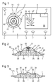
- FIG. 3 A second embodiment of an operating device 30 according to the invention is shown in FIG the figure 3 shown.
- the first rotary encoder 31 In an opening of the user interface 1 is considered a concentric Ring the first rotary encoder 31 inserted, the surface 32 bevelled rising in Direction of the axis of rotation 12 is arranged.
- the first rotary encoder 31 closes immediately to the second rotary encoder 33, which also surrounds the axis of rotation 12 in an annular manner, wherein the rotation axis 12 at the center of the rotational movement of the second encoder 33rd runs.
- the second rotary encoder 33 has an annular recess 34 into which a User can intervene for the rotation of the second encoder.
- first and second rotary encoder 9, 10 fall the axes of rotation of the first and second rotary encoder 9, 10 together.
- the first Encoder surrounds the second encoder, but the axes of rotation do not coincide.
- the entire ring surface of the Encoder is accessible. This is also particularly advantageous because of the Installation in a standard drive bay Parts of the car radio not in neighboring areas should protrude over.
- the display 3 is also direct arranged adjacent to the operating device 2.
- the display separated from the Provide operating device e.g. in a combination instrument that is in front of you Driver is arranged in a vehicle.
- a confirmation of a function selection can in another Ausunmgsform by an actuation of the push button 15 done in various ways.
- a first Actuation can be a first confirmation and a second actuation a be assigned second confirmation.
- the Music titles are stored in a selection list.
- the second type of actuation and the first actuation be executed. If e.g. when confirming a displayed song, the button is shorter than three seconds pressed, only the title is played. If the pushbutton 15 is longer than three Seconds is pressed, so the song is also played and also in the Picklist added for later, immediate selection.
- buttons 15 and 16 are not assigned to the pushbutton 15, e.g. a not shown in the drawing, additional button for switching on and / or off of the car radio can be arranged on the user interface.
Abstract
Description
Die Erfindung geht aus von einer Bedienvorrichtung nach der Gattung des Hauptanspruchs. Es sind schon Bedienvorrichtungen bekannt, bei denen über eine Tastenauswahl oder über eine Drehgeberauswahl bestimmte Funktionen eines durch die Bedienvorrichtung zu steuernden Geräts ausgewählt bzw. zum Aufruf einer ausgewählten Funktion bestätigt werden. Aus der DE 199 36 257 A1 ist ein berührungssensitiver Mehrfachdrehknopf bekannt, bei dem drei Drehknöpfe umeinander herum angeordnet sind. Die Drehknöpfe sind mit Berührungssensoren ausgestattet, so dass die Darstellung auf einer variablen optischen Anzeige an den gerade berührten Drehknopf angepasst werden kann. Die Drehknöpfe können gegebenenfalls auch mit einer Drückfunktion in axialer Richtung zur Bestätigung einer angewählten Funktion ausgestattet werden.The invention is based on an operating device according to the species of Main claim. There are already control devices are known in which a Button selection or via a rotary encoder selected functions of the Operating device to be controlled device selected or to call a selected Function to be confirmed. From DE 199 36 257 A1 is a touch-sensitive Known multiple knob, with three knobs arranged around each other are. The knobs are equipped with touch sensors, so the appearance adjusted on a variable optical display to the knob just touched can be. If necessary, the rotary knobs can also be used with a push function in axial direction to confirm a selected function.
Die erfindungsgemäße Bedienvorrichtung mit den Merkmalen des Hauptanspruchs hat demgegenüber den Vorteil, dass eine zentrale Drucktaste zum Bestätigen einer ausgewählten Einstellung vorgesehen ist. Hierdurch wird vermieden, dass einem zentralen Bedienelement eine Drehfunktion zur Auswahl einer noch zu bestätigenden Funktion zukommt. Hierdurch wird der Bedienkomfort für den Benutzer erhöht, da von der Bedienung her zwischen einer Auswahl und einer Bestätigung unterschieden werden kann, da diese Funktionsarten jeweils verschiedenen Bedienelementen zugeordnet sind. Insbesondere bei einer Nutzung z.B. in einem Kraftfahrzeug kann nicht durch eine versehentlich auf einen Drehknopf axial ausgeübte Kraft eine ausgewählte Funktion bestätigt und damit eingegeben werden. Vielmehr ist für die Bestätigung einer jeweiligen Funktion eine Betätigung eines gesonderten Bedienelements erforderlich, nämlich eine Betätigung der zentralen Drucktaste. Indem zwei Drehgeber vorhanden sind, bei der einer der Drehgeber um den anderen herum angeordnet ist, stehen dennoch benachbart zu der Drucktaste hocheffiziente Eingabeelemente zur Verfügung, mit denen schnell eine Auswahl getroffen werden kann.The operating device according to the invention with the features of the main claim has In contrast, the advantage that a central button to confirm a selected setting. This avoids that one central control a rotation function to select a yet to be confirmed Function comes. This increases the ease of use for the user because of the operation between a selection and a confirmation are distinguished can, because these types of functions are each assigned to different controls. In particular, when used e.g. in a motor vehicle can not by a accidentally applied to a knob axial force exerted a selected function confirmed and entered. Rather, for the confirmation of a respective Function requires an operation of a separate control element, namely a Actuation of the central pushbutton. By having two rotary encoders, one at the encoder is arranged around the other, yet are adjacent to the Pushbutton highly efficient input elements available, with which fast one Selection can be made.
Erfindungsgemäß ist es ferner vorgesehen, die Drucktaste außer zur Bestätigung auch dazu zu verwenden, die Vorrichtung ein- und auszuschalten. Der Ein- und Ausschaltvorgang ist eine besonders wichtige Funktion, die von anderen Auswahlmöglichkeiten vorteilhaft getrennt wird.According to the invention, it is also provided, the pushbutton except for confirmation also to use to turn the device on and off. The inputs and Shutdown is a particularly important feature by others Options are advantageously separated.
Durch die in den Unteransprüchen aufgeführten Maßnahmen sind vorteilhafte Weiterbildungen und Verbesserungen der in den nebengeordneten Ansprüchen angegebenen Bedienvorrichtung möglich. Besonders vorteilhaft ist der Bedienvorrichtung eine Anzeige zugeordnet, in der Funktionen dargestellt sind, die mit dem ersten und/oder dem zweiten Drehgeber auswählbar sind. Hierdurch erhält der Benutzer unmittelbar eine Rückkopplung über von ihm auswälhbare Funktionen. Bevorzugt ist die Darstellung dabei so gewählt, dass eine räumliche Zuordnung zwischen auswählbaren Funktionen und einem in der Anzeige dargestellten, dem ersten und/oder dem zweiten Drehgeber bzw. der Drucktaste entsprechenden Bauteil hergestellt wird. Ein Benutzer kann nun unmittelbar aus der grafischen Darstellung erkennen, welche Funktionen bei einer entsprechenden Drehung eines der Drehgeber ausgewählt bzw. bei einer Betätigung der Drucktaste bestätigt wird.The measures listed in the dependent claims are advantageous Further developments and improvements in the independent claims specified operating device possible. Particularly advantageous is the operating device associated with a display showing functions associated with the first and / or the second encoder are selectable. This gives the user an immediate Feedback via functions that can be selected by him. The illustration is preferred in so doing chosen so that a spatial association between selectable functions and one shown in the display, the first and / or the second encoder or the button corresponding component is produced. A user can now recognize directly from the graphical representation, which functions at a corresponding rotation of one of the encoders selected or upon actuation of the Pushbutton is confirmed.
Bevorzugt ist dabei die Anzeige auf diejenigen Funktionen beschränkt, die bei dem jeweiligen Betriebszustand eines der Bedienvorrichtung zugeordneten Geräts auch tatsächlich auswählbar sind. Insbesondere wird hierdurch erreicht, dass ein Benutzer nicht durch unnötig angezeigte Funktionen abgelenkt wird. Wird z.B. eine Steuerung einer Musikwiedergabe von einem Datenträger vorgenommen, so ist es nicht erforderlich, dass auch auswählbare Sendernamen eines Radiosenders mit angezeigt werden. Eine entsprechende Auswahl eines Senders sollte jedoch dann erfolgen, wenn auf eine Radiosteuerung umgeschaltet wird. Preferably, the display is limited to those functions that in the respective operating state of a device associated with the operating device also are actually selectable. In particular, this ensures that a user does not is distracted by unnecessarily displayed functions. If e.g. a controller of a Music playback made from a disk, so it is not necessary that also selectable station names of a radio station are displayed. A However, appropriate selection of a station should be done when on a Radio control is switched.
Ferner ist es vorteilhaft, mit dem ersten Drehgeber eine Lautstärke einer akustischen Ausgabe zu steuern, während mit dem zweiten Drehgeber eine Funktion eines der Bedienvorrichtung zugeordneten Gerätes oder ein entsprechendes Gerät selbst ausgewählt wird. Diese Zuordnung ermöglicht einerseits eine genaue Einstellung der Lautstärke, die im allgemeinen durch eine Betätigung einer Bestätigungstaste nicht noch bestätigt werden muss. Dagegen tritt der zweite Drehgeber nach der Funktionsauswahl bei einer Betätigung des zentralen Bedienelements unmittelbar in eine gewisse Wechselwirkung mit der Drucktaste zur Bestätigung, da nach der Auswahl erst noch die Bestätigung vorgenommen werden muss. Indem der zweite, innenliegende Drehgeber hierzu verwendet wird, wird die anschließende Bestätigung der Auswahl durch eine Betätigung der Drucktaste für den Benutzer erleichtert.Furthermore, it is advantageous with the first rotary encoder a volume of an acoustic Output while with the second encoder a function of one of Operating device associated device or a corresponding device itself selected becomes. This assignment allows on the one hand a precise adjustment of the volume, the generally not yet confirmed by an operation of a confirmation key got to. In contrast, the second encoder after the function selection occurs at a Actuation of the central control element directly in a certain interaction with the pushbutton for confirmation, because after the selection first the confirmation must be made. By the second, internal rotary encoder this is used, the subsequent confirmation of the selection by an actuation the push button for the user easier.
Zur besseren räumlichen Unterscheidung ist in einer bevorzugten Ausführungsform zwischen dem ersten Drehgeber und dem zweiten Drehgeber ein trennendes Zwischenstück vorgesehen, so dass ein Benutzer bereits erfühlen kann, ob er den ersten Drehgeber oder den zweiten Drehgeber betätigt.For better spatial distinction is in a preferred embodiment between the first encoder and the second encoder a separating Intermediate piece provided so that a user can already feel, whether he is the first Rotary encoder or the second encoder operated.
Vorteilhaft ist ferner vorgesehen, den zweiten Drehgeber pilzförmig auszuführen, so dass er sich zumindest teilweise über den ersten Drehgeber erhebt. Hiermit wird eine Fühlbarkeit des Drehgebers verbessert.Advantageously, it is further provided to perform the second rotary encoder mushroom-shaped, so that he rises at least partially over the first encoder. This will be a Improved feelability of the encoder.
Zur besseren Drehbarkeit sind in einer weiteren Ausführungsform Vertiefungen vorgesehen, in die ein Benutzer eingreifen kann, so dass er das erste Bedienelement leicht bewegen kann.For better rotation in a further embodiment depressions provided, in which a user can intervene, making it the first control easily can move.
Ausführungsbeispiele der Erfindung sind in der Zeichnung dargestellt und in der
nachfolgenden Beschreibung näher erläutert. Es zeigen
Die erfindungsgemäße Bedienvorrichtung kann zur Bedienung beliebiger elektronischer Geräte verwendet werden. Ihre Verwendung ist insbesondere dann vorteilhaft, wenn eine große Anzahl von Auswahlmöglichkeiten zur Verfügung stehen. Insbesondere gegenüber Wipptasten kann hierbei eine höhere Auswahlgeschwindigkeit erreicht werden, da mit einem Drehgeber zwischen einer schnellen und einer langsamen Bewegung durch eine Datenauswahl hindurch leichter umgeschaltet werden kann. Insbesondere bei Radiovorrichtungen und Musikwiedergabevorrichtungen haben sich gegenüber der Vergangenheit die Auswahlmöglichkeiten stark erhöht. So ist es z.B. möglich, auf einem Datenträger, z.B. einer CD, mehr als hundert Musiktitel in einem komprimierten Datenformat, z.B. im sogenannten MP3-Format, abzulegen. Durch digitalen Rundfunk ist es möglich, hundert und mehr Programme empfangen zu können. Insbesondere bei einer Steuerung eines Autoradios ist es dabei erforderlich, dem Benutzer die Auswahl möglichst so anzubieten, dass er nicht oder möglichst wenig vom Verkehrsgeschehen abgelenkt wird. Zudem muss die Bedienung leicht erlernbar sein, da auch Fahrer, die ein Fahrzeug erstmalig oder erst kurzfristig nutzen, z.B. in einem Mietwagen, in der Lage sein müssen, eine entsprechende Bedienung durchzuführen. Im Folgenden wird daher die erfindungsgemäße Bedienvorrichtung am Beispiel einer Verwendung an einem Autoradio in einem Kraftfahrzeug erläutert.The operating device according to the invention can be used to operate any electronic Devices are used. Their use is particularly advantageous when a large number of choices are available. Especially opposite Rocker buttons this can be achieved a higher selection speed, as with a rotary encoder between a fast and a slow movement through a Data selection can be easily switched through. Especially at Radiovorrichtungen und Musikvoriedergevewrichtungen have opposed the Past the choices greatly increased. So it is e.g. possible, on one Data carriers, e.g. a CD, more than a hundred songs in a compressed Data format, e.g. in the so-called MP3 format, store. Through digital broadcasting is it is possible to receive a hundred and more programs. Especially with a Control of a car radio it is necessary to give the user the choice if possible to offer so that he does not or as little as possible from the traffic is distracted. In addition, the operation must be easy to learn, as well as drivers who Use the vehicle for the first time or at short notice, e.g. in a rental car, able must be to perform an appropriate operation. The following is therefore the Control device according to the invention using the example of a car radio explained in a motor vehicle.
In der Figur 1 ist eine Bedienoberfläche 1 eines Autoradios dargestellt, das in einem
Einbauschacht in einem Kraftfahrzeug angeordnet ist. Auf der Bedienoberfläche 1 ist eine
Bedienvorrichtung 2 neben einer Anzeige 3 angeordnet. Bevorzugt sind neben der
Bedienvorrichtung 2 noch weitere Bedienelemente auf der Bedienoberfläche 1
vorgesehen. Dies ist z.B. ein Auslöseknopf 5 zum Abklappen oder Entnehmen der
Bedienoberfläche 1 von dem übrigen Autoradio in dem Einbauschacht. Ferner ist bei dem
hier gezeigten Ausführungsbeispiel eine Hauptmenü-Taste 4 vorgesehen, bei deren
Betätigung die Autoradiovorrichtung in einen definierten Ausgangszustand geschaltet
wird. Ferner sind benachbart zu der Anzeige 3 weitere Bedientasten vorgesehen. Eine
erste Taste 6, dient einer Quellenwahl, eine zweite Taste 7 einer Diensteauswahl und eine
dritte Taste 8 einer Auswahl zur Klangeinstellung.1 shows a
Die Bedienvorrichtung 2 weist einen ersten Drehgeber 9 auf, der ringförmig in die
Bedienoberfläche 1 des Autoradios eingebracht ist. Der erste Drehgeber 9 ist derart
gelagert, dass er in beide Richtungen des dargestellten Doppelpfeiles 11 konzentrisch um
eine durch ein Kreuz gekennzeichnete Drehachse 12 gedreht werden kann. Innerhalb des
Rings des ersten Drehgebers 9 ist ein zweiter Drehgeber 10 angeordnet. Auch der zweite
Drehgeber 10 ist in einer bevorzugten Ausführungsform konzentrisch um die Drehachse
12 in der Ebene der Bedienoberfläche 1 drehbar. Der zweite Drehgeber 10 ist ebenfalls
bevorzugt ringförmig ausgeführt. Er ist außerdem in beide Richtung entsprechend der
Pfeildarstellung 11 um die Drehachse 12 drehbar. Er umschließt eine Drucktaste 15. Auf
die Drucktaste 15 kann senkrecht zu der Bedienoberfläche 1 eine Kraft so ausgeübt
werden, dass die Druckstaste 15 axial zu der Drehachse 12 verschiebbar ist.The
In einer bevorzugten Ausführungsform ist zwischen dem ersten Drehgeber 9 und dem
zweiten Drehgeber 10 ein Zwischenstück 13 vorgesehen, das den ersten Drehgeber 9 von
dem zweiten Drehgeber 10 trennt. Damit ist für einen Benutzer ein Übergang von dem
ersten Drehgeber 9 zu dem zweiten Drehgeber 10 erfühlbar. In einem in der Figur 1 nicht
dargestellten Ausführungsbeispiel kann der erste Drehgeber 9 auch unmittelbar an den
zweiten Drehgeber 10 anschließen.In a preferred embodiment is between the
In einer bevorzugten Ausführungsform ist auf der Bedienoberfläche 1 eine Beschriftung
14 für den ersten Drehgeber 9 und auf dem Zwischenstück 13 eine Beschriftung 16 für
den zweiten Drehgeber 10 angeordnet, so dass eine Funktion der Drehgeber für einen
Benutzer unmittelbar ersichtlich ist. In einer nicht gezeigten Ausführungsform können die
Beschriftungen auch unmittelbar auf den Drehgebern 9, 10 selbst angeordnet sein.In a preferred embodiment, on the
Eine Bedienung der Drehgeber wird bevorzugt elektronisch ausgewertet. Die Drehgeber
sind dabei so bedienbar, dass sie ohne eine Begrenzung in jede der beiden angezeigten
Richtungen (Pfeil 11) bewegt werden können. Bevorzugt sind die Drehgeber dabei so
beweglich, dass eine Bewegung lediglich in festgelegten, gerasterten Schritten möglich
ist. Durch die Rasterung wird einem Benutzer eine haptische Rückmeldung über einen
durchgeführten Bewegungsschritt des jeweiligen Drehgebers 9, 10 gegeben. Er kann
damit eine Bewegung des Drehgebers auch dann erfühlen, wenn er den Drehgeber bei der
Bedienung selbst nicht betrachtet.An operation of the rotary encoder is preferably evaluated electronically. The encoders
are so operable that they are displayed without a limit in each of the two
Directions (arrow 11) can be moved. Preferably, the encoders are doing so
movable, that allows movement only in fixed, rasterized steps
is. Rasterization provides the user with haptic feedback about a user
performed movement step of the respective
In einer besonderen Ausführungsform des Autoradios ist der erste Drehgeber 9 einer
Lautstärkeneinstellung des Autoradios zugeordnet. Bei einer Bewegung im Uhrzeigersinn
wird die Lautstärke einer Audioausgabe erhöht, z.B. die Lautstärke einer Ausgabe eines
Radioprogramms über einen Lautsprecher. Bei einer Bewegung gegen den Uhrzeigersinn
wird die Lautstärke der Audioausgabe verringert. Der zweite Drehgeber 10 dient dagegen
einer Funktionsauswahl des Autoradios. Der zweite Drehgeber 10 wirkt hierzu mit der
Anzeige 3 zusammen. In der Anzeige 3 ist in einem Anzeigefeld 17 dargestellt, welche
Funktion des Autoradios bzw. welches mit dem Autoradio verbundene Gerät, z.B. CD-Wechsler
oder Navigationseinheit, derzeit mit dem Drehgeber angesteuert wird. In einer
übrigen Anzeigefläche 18 ist die Drucktaste 15 bildlich dargestellt (Bezugszeichen 15').
Um die Darstellung der Drucktaste 15' herum sind einzelne Funktionen des Autoradios
dargestellt, die in dem jeweiligen Betriebszustand, der durch die Anzeige in dem
Anzeigefeld 17 gekennzeichnet ist, auswählbar sind. Eine der Funktionen ist durch einen
Auswahlrahmen 20 gekennzeichnet. Statt eines Auswahlrahmens kann auch eine inverse
Anzeige oder eine auf andere Weise hervorgehobene Darstellung der jeweils
ausgewählten Funktion erfolgen.In a particular embodiment of the car radio, the first
In einer bevorzugten Ausführungsform ist der Auswahlrahmen 20 durch eine
Verbindungslinie 41 mit der Darstellung der Drucktaste 15' in der Anzeigefläche 18
verbunden. Hierdurch wird einem Benutzer verdeutlicht, dass durch eine Betätigung der
Drucktaste 15 die in dem Auswahlrahmen 20 dargestellte Funktion 19 ausgelöst wird. Ein
Wechsel zur Auswahl einer anderen Funktion erfolgt dadurch, dass der zweite Drehgeber
10 um die Drehachse 12 gedreht wird. Erfolgt eine Drehung im Uhrzeigersinn, so bewegt
sich auch der Auswahlrahmen 20 im Uhrzeigersinn durch die um die Darstellung 15' der
Bestätigungstaste herum gruppierten Funktionen. Erfolgt eine Drehung des zweiten
Drehgebers 10 in Richtung gegen den Uhrzeigersinn, so wird auch der Auswahlrahmen in
der gleichen Richtung um die Darstellung der Bestätigungstaste 15' herum verschoben.
Entsprechend kann auch eine Auswahl aus einer Liste erfolgen, wobei durch eine
Drehung im Uhrzeigersinn den Auswahlrahmen 20 in der Liste nach unten und bei einer
Drehung im Uhrzeigersinn in der Liste nach oben bewegt wird.In a preferred embodiment, the
Ein Wechsel in ein anderes Menü erfolgt dabei entweder dadurch, dass eine Auswahl
eines anderen Menüs als Funktion in der Anzeigefläche 18 dem Benutzer angeboten und
von diesem ausgewählt und bestätigt wird. In einer anderen Ausführungsform kann ein
Wechsel in ein anderes Menü auch durch eine Betätigung einer der Tasten 6, 7, 8 neben
der Anzeige 3 erfolgen. Die Tasten 6, 7, 8 können auch dazu ausgelegt sein, bestimmte
Funktionen unmittelbar auszulösen. Ein Wechsel in ein anderes Menü erfolgt z.B. auch
durch eine Betätigung der Hauptmenü-Taste 4, mit der unmittelbar ein eingestelltes,
vorzugsweise anderen Menüs übergeordnetes Menü aufgerufen wird. Die Hauptmenü-Taste
4 kann in einer anderen Ausführung auch mit einem Aufruf eines von einem
Benutzer persönlich konfigurierten Menüs belegt werden.A change to another menu is done either by a selection
another menu as a function in the
In einer anderen Ausführungsform kann der zweite Drehgeber 10 auch dazu verwendet
werden, den Auswahlrahmen 20 durch eine zumindest teilweise in der Anzeige 3
angezeigte und z.B. alphabetisch geordnete Liste zu verschieben. In einer bevorzugten
Ausführungsform ist dabei die Bewegungsgeschwindigkeit des Auswahlrahmens 20 von
einer Bewegungsgeschwindigkeit des zweiten Drehgebers 10 abhängig. Wird der zweite
Drehgeber 10 schnell bewegt, so wird auch entsprechend die Bewegungsgeschwindigkeit,
gegebenenfalls sogar überproportional gegenüber einer Bewegungsgeschwindigkeit des
Auswahlrahmens 20 bei einer langsamen Bewegung des zweiten Drehgebers 10 erhöht.In another embodiment, the second
Der erste Drehgeber 9 ist unabhängig von dem zweiten Drehgeber 10 betätigbar. So ist es
z.B. möglich, wenn ein bestimmtes Untermenü oder eine bestimmte Auswahlfunktion
mittels des zweiten Drehgebers ausgewählt wurde, diese Auswahl zu unterbrechen und
die Lautstärke des Autoradios mit dem ersten Drehgeber 9 zu verändern. Anschließend
kann mit der Auswahl mittels dem zweiten Drehgeber 10 fortgefahren werden, ohne dass
die Einstellung in der Anzeige 3 verändert werden musste.The first
In einer weiteren Ausführungsform ist es auch möglich, die Funktionszuordnung des
ersten Drehgebers 9 und des zweiten Drehgebers 10 zu vertauschen. Durch die räumliche
Nähe des zweiten Drehgebers 10 zu der Drucktaste 15 ist jedoch die Auswahlfunktion
unmittelbar benachbart zu der Bestätigungsfunktion angeordnet, wenn der zweite
Drehgeber 10 der Auswahlfunktion dient.In a further embodiment, it is also possible to assign the function assignment of
Unter einer Auswahl ist insgesamt sowohl die Auswahl einer bestimmten Funktion eines
Gerätes, jedoch auch die Auswahl eines mit dem Autoradio verbundenen Gerätes an sich
zu verstehen. Eine entsprechende Auswahl eines Gerätes wird dann vorgenommen, wenn
der Benutzer die erste Taste 6 betätigt hat, die als Auswahltaste dient. In der
Anzeigefläche 18 werden ihm dann verschiedene, mit dem Autoradio verbundene oder in
dieses integrierte Geräte bzw. Baugruppen- oder Funktionsbestandteile angeboten. Dies
kann einerseits eine Navigationsausgabe, eine CD-Wiedergabe, ein DAB-Empfang, ein
UKW-Empfang oder eine sonstige Auswahl einer Audioquelle sein. In einem
Dienstemenü, das mit der zweiten Taste 7 aufgerufen wird, werden dem Benutzer
verschiedne Empfangsmodi, z.B. ein Programmtyp-Empfang, ein Verkehrsfunkempfang
oder eine Auswahl regionaler Sender angeboten. Über eine Betätigung der dritten Taste 8
gelangt ein Benutzer in eine Audioauswahl, bei der Höhen, Tiefen, die Balance zwischen
den Stereolautsprechern oder bestimmte Klangmuster (Equilizer-Funktion) eingestellt
werden können.Under a selection is altogether both the selection of a certain function of a
Device, but also the selection of a device connected to the car radio itself
to understand. A corresponding selection of a device is made when
the user has pressed the
Die jeweiligen, dargestellten Auswahlfunktionen sind insbesondere davon abhängig, welche Audioquelle gewählt wurde. So unterscheiden sich die wählbaren Funktionen für die verschiedenen Datenquellen, da z.B. eine Senderauswahl bei einer Radiofunktion gegenüber einer Musiktitelauswahl bzw. Interpretenauswahl z.B. bei einer CD-Wiedergabe eine Auswahl aus unterschiedlichen Befehlen verlangt. Gegebenenfalls ist es auch möglich, einen Datenträger aus einer Vielzahl im Fahrzeug vorhandener Datenträger auszuwählen. Gegebenenfalls können auch Musikart, Liedtitel oder ein Musik-Album mittels einer Texteingabe ausgewählt werden.The respective selection functions shown are particularly dependent on which audio source was selected. This is how the selectable functions differ for the various data sources, e.g. a station selection in a radio function to music title selection or artist selection e.g. in a CD playback requires a choice of different commands. If necessary it is also possible, a disk from a variety in the vehicle existing disk select. If necessary, music genre, song titles or a music album can also be used be selected by means of a text input.
In einer weiteren Ausführungsform ist es auch möglich, mittels des ersten und/oder des
zweiten Drehgebers eine Buchstabenauswahl vorzunehmen, so dass durch eine
Aneinanderfolgen von Buchstaben auch Wörter mittels der Drehgeber 9, 10 eingegeben
werden können.In a further embodiment, it is also possible by means of the first and / or the
second encoder to make a letter selection, so that by a
Sequences of letters also words by means of the
In der Figur 2 ist ein ersten Ausführungsbeispiel für eine erfindungsgemäße
Bedienvorrichtung 40 in einer Seitenansicht im Querschnitt gezeigt. Ein zweiter
Drehgeber 21 ist konzentrisch zu der Drehachse 12 im Zentrum der Bedienvorrichtung
angeordnet. Der zweite Drehgeber 21 weist ein Oberteil 22 auf, das beabstandet zu der
Bedienoberfläche 1 des Autoradios angeordnet ist und sich über die Bedienoberfläche 1
und um seine Umgebung erhebt. In das Oberteil 22 ist eine Drucktaste 23 eingelassen, die
axial zu der Drehachse 12 beweglich gelagert ist. Das Oberteil 22 ist in etwa pilzförmig
ausgeführt, so dass ein Benutzer zumindest teilweise in einen Spalt 24 zwischen dem
zweiten Drehgeber 21 und einem Zwischenstück 25 so eingreifen kann, dass der zweite
Drehgeber 21 bequem gefasst und um die Drehachse 12 gedreht werden kann. Das
Zwischenstück 25 ist so angeordnet, dass es von einem Benutzer bei einer Betätigung der
Bedienvorrichtung 40 nicht verdreht werden kann. Es trennt damit den zweiten
Drehgeber 21 von dem ersten Drehgeber 26, der sowohl das Zwischenstück 25 als auch
den zweiten Drehgeber 21 konzentrisch umgibt. An dem ersten Drehgeber 26 sind
Erhöhungen 27 angeordnet, die eine leichte Greifbarkeit des ersten Drehgebers 26
ermöglichen. Elektronische Auswerteschaltungen der Drehgeber 21, 26 sowie der
Drucktaste 23 sind in der Figur 2 nicht dargestellt. Bevorzugt ist eine Oberfläche 28 des
ersten Drehgebers 26 gegenüber der Bedienoberfläche 1 angeschrägt, so dass der erste
Drehgeber 26 leicht aufgefunden sowie leicht gefasst und gedreht werden kann.In the figure 2 is a first embodiment of an
Ein zweites Ausführungsbeispiel für eine erfindungsgemäße Bedienvorrichtung 30 ist in
der Figur 3 dargestellt. In eine Öffnung der Bedienoberfläche 1 ist als ein konzentrischer
Ring der erste Drehgeber 31 eingelassen, dessen Oberfläche 32 angeschrägt ansteigend in
Richtung der Drehachse 12 angeordnet ist. Der erste Drehgeber 31 schließt unmittelbar
an den zweiten Drehgeber 33 an, der ebenfalls die Drehachse 12 ringförmig umschließt,
wobei die Drehachse 12 im Mittelpunkt der Drehbewegung des zweiten Drehgebers 33
verläuft. Der zweite Drehgeber 33 weist eine ringförmige Vertiefung 34 auf, in die ein
Benutzer für die Drehung des zweiten Drehgebers eingreifen kann. Zur besseren
Greifbarkeit sind Querrippen 35 vorgesehen, die beabstandet in der Vertiefung 34
angeordnet sind und die zentrisch zu der Drehachse 12 hin ausgerichtet sind. Der zweite
Drehgeber 33 umgibt eine Drucktaste 36, durch die die Drehachse 12 verläuft und die
axial zu der Drehachse 12 zur Bestätigung bewegt werden kann.A second embodiment of an operating
Bei dem hier dargestellten Ausführungsbeispiel fallen die Drehachsen des ersten und des
zweiten Drehgebers 9, 10 jeweils zusammen. Es ist jedoch auch möglich, dass der erste
Drehgeber den zweiten Drehgeber umschließt, die Drehachsen sich jedoch nicht decken.
Ferner ist es für eine erfindungsgemäße Bedienvorrichtung nicht notwendiger Weise
erforderlich, dass der erste Drehgeber bzw. der zweite Drehgeber über ihre gesamte
Fläche hin von der Oberseite her greifbar sind. Es ist z.B. auch möglich, dass zumindest
einer der beiden Drehgeber nur teilweise aus einer Überdeckung herausragt. Für eine
Anbringung in einem Autoradio ist es jedoch vorteilhaft, dass die gesamte Ringfläche des
Drehgebers zugänglich ist. Dies ist auch insbesondere deshalb von Vorteil, da für den
Einbau in einem genormten Einbauschacht Teile des Autoradios nicht in Nachbarbereiche
herüberragen sollten.In the embodiment shown here fall the axes of rotation of the first and
second
Bei dem hier dargestellten Ausführungsbeispiel ist ferner die Anzeige 3 unmittelbar
benachbart zu der Bedienvorrichtung 2 angeordnet. In einer weiteren, in der Zeichnung
nicht dargestellten Ausführungsform ist es auch möglich, die Anzeige getrennt von der
Bedienvorrichtung vorzusehen, z.B. in einem Kombinationsinstrument, das vor einem
Fahrer in einem Fahrzeug angeordnet ist. In the embodiment shown here, the
Eine Bestätigung einer Funktionsauswahl kann in einer weiteren Ausfühnmgsform durch
eine Betätigung der Drucktaste 15 in verschiedener Weise erfolgen. Einer ersten
Betätigungsart kann dabei eine erste Bestätigung und einer zweiten Betätigungsart eine
zweite Bestätigung zugeordnet sein. Beispielsweise bei einem angezeigten Musiktitel
kann bei einer Betätigung nach der ersten Betätigungsart eine Wiedergabe des Musiktitels
gestartet werden. Bei einer Betätigung nach der zweiten Bestätigungsart kann der
Musiktitel in einer Auswahlliste abgelegt werden. Je nach Ausführung kann bei Aufruf
der zweiten Betätigungsart auch die erste Betätigungsart ausgeführt werden. Wird z.B.
bei der Bestätigung eines angezeigten Musiktitels die Taste kürzer als drei Sekunden
gedrückt, so wird lediglich der Titel gespielt. Wird die Drucktaste 15 länger als drei
Sekunden gedrückt, so wird der Musiktitel ebenfalls wiedergegeben und außerdem in die
Auswahlliste für eine spätere, unmittelbare Auswahl aufgenommen.A confirmation of a function selection can in another Ausfühnmgsform by
an actuation of the
Der Drucktaste 15 kann neben der Bestätigungsfunktion einer entsprechenden mit den
Drehgebern 9, 10 getroffene Auswahl auch die Funktion des Einschaltens und des
Ausschaltens des durch die Bedienvorrichtung gesteuerten Geräts dienen. Hierfür ist eine
Bedienung der Bestätigungstaste erforderlich, die sich von einer reinen Bestätigung einer
Auswahlfunktion unterscheidet. Es ist z.B. möglich, für ein Ausschalten des Gerätes die
Bestätigungstaste über eine vorgegebene Zeitgrenze, z.B. zwei Sekunden, hinaus
gedrückt zu halten. Ferner ist es auch möglich, ein Ausschalten des Geräts von einer
aufeinanderfolgenden Betätigung der Bestätigungstaste, also z.B. ein
aufeinanderfolgendes, zweimaliges Drücken, abhängig zu gestalten. Ein Einschalten des
Gerätes kann jedoch unmittelbar dann erfolgen, wenn die Drucktaste 15 oder ― in einer
weiteren Ausführungsform ― jede beliebige Taste des Autoradios in ausgeschaltetem
Zustand betätigt wird. In einer weiteren Ausführungsform ist es jedoch auch möglich, ein
Einschalten von einer längeren Betätigung der Drucktaste 15 abhängig zu machen.The
Wird die Ein- und/oder Ausschaltfunktion nicht der Drucktaste 15 zugeordnet, kann z.B.
eine in der Zeichnung nicht dargestellte, zusätzlich Taste zum Ein- und/oder Ausschalten
des Autoradios auf der Bedienoberfläche angeordnet werden.If the on and / or off function is not assigned to the
Claims (9)
Applications Claiming Priority (2)
| Application Number | Priority Date | Filing Date | Title |
|---|---|---|---|
| DE10358856 | 2003-12-16 | ||
| DE2003158856 DE10358856A1 (en) | 2003-12-16 | 2003-12-16 | operating device |
Publications (3)
| Publication Number | Publication Date |
|---|---|
| EP1544880A2 true EP1544880A2 (en) | 2005-06-22 |
| EP1544880A3 EP1544880A3 (en) | 2008-01-23 |
| EP1544880B1 EP1544880B1 (en) | 2012-05-02 |
Family
ID=34485401
Family Applications (1)
| Application Number | Title | Priority Date | Filing Date |
|---|---|---|---|
| EP04105397A Expired - Fee Related EP1544880B1 (en) | 2003-12-16 | 2004-10-29 | Control device |
Country Status (2)
| Country | Link |
|---|---|
| EP (1) | EP1544880B1 (en) |
| DE (1) | DE10358856A1 (en) |
Cited By (7)
| Publication number | Priority date | Publication date | Assignee | Title |
|---|---|---|---|---|
| WO2008014327A1 (en) * | 2006-07-28 | 2008-01-31 | Bose Corporation | Control knob with safety feature |
| DE102007029034A1 (en) * | 2007-06-23 | 2008-12-24 | Bayerische Motoren Werke Aktiengesellschaft | Display device for motor vehicle, comprises multiple display elements, where each display element is operated independently by driver assistance system from multiple driver assistance systems of vehicle |
| DE102007029032A1 (en) * | 2007-06-23 | 2008-12-24 | Bayerische Motoren Werke Aktiengesellschaft | Operating device for influencing on-states of e.g. collision warning system, of motor vehicle, has switching elements assigned to assistance system for outputting of warning whose time criticality measure is provided in predetermined areas |
| DE102011003586A1 (en) | 2011-02-03 | 2012-08-09 | Robert Bosch Gmbh | Knob-shaped multifunction control element for controlling computer units in motor car, has rotary engagement surfaces provided on different portions on periphery of control element such that surfaces are diametrically opposed to each other |
| DE102014222670A1 (en) * | 2014-11-06 | 2016-05-12 | Volkswagen Aktiengesellschaft | Operating device in a motor vehicle |
| WO2017115172A1 (en) * | 2015-12-31 | 2017-07-06 | Abb Global Industries And Services Pvt. Ltd | Control device for controlling electrical devices |
| WO2018134000A1 (en) * | 2017-01-18 | 2018-07-26 | Ma Lighting Technology Gmbh | Lighting control console having a dual rotary encoder |
Citations (2)
| Publication number | Priority date | Publication date | Assignee | Title |
|---|---|---|---|---|
| US5665946A (en) | 1994-10-07 | 1997-09-09 | Alps Electric Co., Ltd. | Combined-operation type switching apparatus including rotational and push operators |
| DE19936257A1 (en) | 1999-07-31 | 2001-02-01 | Georg Geiser | Touch-sensitive multiple rotary knob for adaptable dialog procedure |
Family Cites Families (1)
| Publication number | Priority date | Publication date | Assignee | Title |
|---|---|---|---|---|
| JPH0877694A (en) * | 1994-09-05 | 1996-03-22 | Yamaha Corp | Operating chip unit |
-
2003
- 2003-12-16 DE DE2003158856 patent/DE10358856A1/en not_active Withdrawn
-
2004
- 2004-10-29 EP EP04105397A patent/EP1544880B1/en not_active Expired - Fee Related
Patent Citations (2)
| Publication number | Priority date | Publication date | Assignee | Title |
|---|---|---|---|---|
| US5665946A (en) | 1994-10-07 | 1997-09-09 | Alps Electric Co., Ltd. | Combined-operation type switching apparatus including rotational and push operators |
| DE19936257A1 (en) | 1999-07-31 | 2001-02-01 | Georg Geiser | Touch-sensitive multiple rotary knob for adaptable dialog procedure |
Cited By (12)
| Publication number | Priority date | Publication date | Assignee | Title |
|---|---|---|---|---|
| WO2008014327A1 (en) * | 2006-07-28 | 2008-01-31 | Bose Corporation | Control knob with safety feature |
| US7479607B2 (en) | 2006-07-28 | 2009-01-20 | Bose Corporation | Control knob with safety feature |
| DE102007029034A1 (en) * | 2007-06-23 | 2008-12-24 | Bayerische Motoren Werke Aktiengesellschaft | Display device for motor vehicle, comprises multiple display elements, where each display element is operated independently by driver assistance system from multiple driver assistance systems of vehicle |
| DE102007029032A1 (en) * | 2007-06-23 | 2008-12-24 | Bayerische Motoren Werke Aktiengesellschaft | Operating device for influencing on-states of e.g. collision warning system, of motor vehicle, has switching elements assigned to assistance system for outputting of warning whose time criticality measure is provided in predetermined areas |
| DE102011003586A1 (en) | 2011-02-03 | 2012-08-09 | Robert Bosch Gmbh | Knob-shaped multifunction control element for controlling computer units in motor car, has rotary engagement surfaces provided on different portions on periphery of control element such that surfaces are diametrically opposed to each other |
| DE102014222670A1 (en) * | 2014-11-06 | 2016-05-12 | Volkswagen Aktiengesellschaft | Operating device in a motor vehicle |
| WO2017115172A1 (en) * | 2015-12-31 | 2017-07-06 | Abb Global Industries And Services Pvt. Ltd | Control device for controlling electrical devices |
| WO2018134000A1 (en) * | 2017-01-18 | 2018-07-26 | Ma Lighting Technology Gmbh | Lighting control console having a dual rotary encoder |
| WO2018134001A1 (en) * | 2017-01-18 | 2018-07-26 | Ma Lighting Technology Gmbh | Light control operating unit having a double-shaft encoder |
| US10149373B2 (en) | 2017-01-18 | 2018-12-04 | Ma Lighting Technology Gmbh | Lighting control console having a dual encoder |
| US10595386B2 (en) | 2017-01-18 | 2020-03-17 | Ma Lighting Technology Gmbh | Lighting control console having a dual encoder |
| US10820393B2 (en) | 2017-01-18 | 2020-10-27 | Ma Lighting Technology Gmbh | Lighting control operating unit having a dual encoder |
Also Published As
| Publication number | Publication date |
|---|---|
| EP1544880B1 (en) | 2012-05-02 |
| DE10358856A1 (en) | 2005-07-14 |
| EP1544880A3 (en) | 2008-01-23 |
Similar Documents
| Publication | Publication Date | Title |
|---|---|---|
| EP1337414B1 (en) | Multifunction operating device | |
| EP2150883B1 (en) | Multifunction display and operating device and method for operating a multifunction display and operating device having improved selection operation | |
| EP1212208B1 (en) | Multifunctional operating device | |
| EP1762421B1 (en) | Operating switch assembly for motor vehicle | |
| EP2328783B1 (en) | Operator control element for a display apparatus in a transportation means | |
| EP1075979B1 (en) | Method of operating a multifunction operation device in motor vehicles and multifunction operating device | |
| DE102010035731A1 (en) | Vehicle steering device with vehicle steering wheel | |
| WO2007121977A2 (en) | Control system for a vehicle cockpit | |
| EP1953029B1 (en) | Display and operational device with improved option possibilities of up-to-date display and operational contexts | |
| WO2006061060A1 (en) | Multi-function operating device for motor vehicles | |
| WO2013159911A2 (en) | Multifunctional operating device, in particular for a motor vehicle | |
| DE10050223A1 (en) | Multifunction display and control device enables continuous, multi-step or list-type setting or selection by turning further input element, menu point selection by moving it in translation | |
| WO2009033523A2 (en) | Operating system for a motor vehicle | |
| DE10205641A1 (en) | Multi-function operator and control device e.g. for motor vehicle CD or radio, includes function-selection element for selecting terminal to be operated | |
| EP1544880B1 (en) | Control device | |
| EP1403619A1 (en) | Input device | |
| DE102006053499B4 (en) | Steering wheel switch module for a motor vehicle | |
| DE102006030538B4 (en) | Multifunction radio control panel | |
| DE10059793A1 (en) | Multifunction control device for motor vehicle has at least one bi-directionally rotatable control element with setting ring enclosing axially operated control elements | |
| DE102005043297A1 (en) | Steering wheel with switch arrangement for motor vehicle has switch arrangement with four switch elements in cross formation, able to be individually operated and with touch surfaces with different heights | |
| DE202006017330U1 (en) | Automobile steering wheel has a number of inserted input control modules that fit into the steering wheel | |
| WO2020083544A1 (en) | Steering wheel, motor vehicle, and method for operating a motor vehicle | |
| DE10237725A1 (en) | Multi-function motor vehicle device for a hierarchical menu structure with multiple menus has a control element to select functions in the structure and a screen to display each selected function | |
| EP1186460B1 (en) | Multimedia control system and method for using a multimedia system | |
| DE19959702A1 (en) | Display and control unit, has multi-function button with touch feedback of triggering of current button function and whereby functions to be triggered can be distinguished by touch |
Legal Events
| Date | Code | Title | Description |
|---|---|---|---|
| PUAI | Public reference made under article 153(3) epc to a published international application that has entered the european phase |
Free format text: ORIGINAL CODE: 0009012 |
|
| AK | Designated contracting states |
Kind code of ref document: A2 Designated state(s): AT BE BG CH CY CZ DE DK EE ES FI FR GB GR HU IE IT LI LU MC NL PL PT RO SE SI SK TR |
|
| AX | Request for extension of the european patent |
Extension state: AL HR LT LV MK |
|
| PUAL | Search report despatched |
Free format text: ORIGINAL CODE: 0009013 |
|
| AK | Designated contracting states |
Kind code of ref document: A3 Designated state(s): AT BE BG CH CY CZ DE DK EE ES FI FR GB GR HU IE IT LI LU MC NL PL PT RO SE SI SK TR |
|
| AX | Request for extension of the european patent |
Extension state: AL HR LT LV MK |
|
| 17P | Request for examination filed |
Effective date: 20080723 |
|
| AKX | Designation fees paid |
Designated state(s): DE FR GB IT |
|
| 17Q | First examination report despatched |
Effective date: 20100308 |
|
| GRAP | Despatch of communication of intention to grant a patent |
Free format text: ORIGINAL CODE: EPIDOSNIGR1 |
|
| GRAS | Grant fee paid |
Free format text: ORIGINAL CODE: EPIDOSNIGR3 |
|
| GRAA | (expected) grant |
Free format text: ORIGINAL CODE: 0009210 |
|
| AK | Designated contracting states |
Kind code of ref document: B1 Designated state(s): DE FR GB IT |
|
| REG | Reference to a national code |
Ref country code: GB Ref legal event code: FG4D Free format text: NOT ENGLISH |
|
| REG | Reference to a national code |
Ref country code: DE Ref legal event code: R096 Ref document number: 502004013486 Country of ref document: DE Effective date: 20120705 |
|
| PG25 | Lapsed in a contracting state [announced via postgrant information from national office to epo] |
Ref country code: IT Free format text: LAPSE BECAUSE OF FAILURE TO SUBMIT A TRANSLATION OF THE DESCRIPTION OR TO PAY THE FEE WITHIN THE PRESCRIBED TIME-LIMIT Effective date: 20120502 |
|
| PLBE | No opposition filed within time limit |
Free format text: ORIGINAL CODE: 0009261 |
|
| STAA | Information on the status of an ep patent application or granted ep patent |
Free format text: STATUS: NO OPPOSITION FILED WITHIN TIME LIMIT |
|
| 26N | No opposition filed |
Effective date: 20130205 |
|
| REG | Reference to a national code |
Ref country code: DE Ref legal event code: R097 Ref document number: 502004013486 Country of ref document: DE Effective date: 20130205 |
|
| GBPC | Gb: european patent ceased through non-payment of renewal fee |
Effective date: 20121029 |
|
| PG25 | Lapsed in a contracting state [announced via postgrant information from national office to epo] |
Ref country code: GB Free format text: LAPSE BECAUSE OF NON-PAYMENT OF DUE FEES Effective date: 20121029 |
|
| PGFP | Annual fee paid to national office [announced via postgrant information from national office to epo] |
Ref country code: FR Payment date: 20141021 Year of fee payment: 11 |
|
| REG | Reference to a national code |
Ref country code: FR Ref legal event code: ST Effective date: 20160630 |
|
| PG25 | Lapsed in a contracting state [announced via postgrant information from national office to epo] |
Ref country code: FR Free format text: LAPSE BECAUSE OF NON-PAYMENT OF DUE FEES Effective date: 20151102 |
|
| PGFP | Annual fee paid to national office [announced via postgrant information from national office to epo] |
Ref country code: DE Payment date: 20161213 Year of fee payment: 13 |
|
| REG | Reference to a national code |
Ref country code: DE Ref legal event code: R119 Ref document number: 502004013486 Country of ref document: DE |
|
| PG25 | Lapsed in a contracting state [announced via postgrant information from national office to epo] |
Ref country code: DE Free format text: LAPSE BECAUSE OF NON-PAYMENT OF DUE FEES Effective date: 20180501 |