EP1543354B1 - Method and apparatus for visually inspecting a substrate on a printing press - Google Patents
Method and apparatus for visually inspecting a substrate on a printing press Download PDFInfo
- Publication number
- EP1543354B1 EP1543354B1 EP03754447A EP03754447A EP1543354B1 EP 1543354 B1 EP1543354 B1 EP 1543354B1 EP 03754447 A EP03754447 A EP 03754447A EP 03754447 A EP03754447 A EP 03754447A EP 1543354 B1 EP1543354 B1 EP 1543354B1
- Authority
- EP
- European Patent Office
- Prior art keywords
- printing press
- visual inspection
- substrate
- image recording
- recording device
- Prior art date
- Legal status (The legal status is an assumption and is not a legal conclusion. Google has not performed a legal analysis and makes no representation as to the accuracy of the status listed.)
- Expired - Fee Related
Links
Images


Classifications
-
- B—PERFORMING OPERATIONS; TRANSPORTING
- B41—PRINTING; LINING MACHINES; TYPEWRITERS; STAMPS
- B41F—PRINTING MACHINES OR PRESSES
- B41F33/00—Indicating, counting, warning, control or safety devices
- B41F33/0036—Devices for scanning or checking the printed matter for quality control
Definitions
- the present invention relates generally to the field of printing presses, and specifically to a method and apparatus for visually inspecting images on a substrate moving along a printing press using an image recording assembly comprising an image recording device and light emitting diode (“LED”) illumination source.
- LED light emitting diode
- a web of material typically paper
- a storage mechanism such as a reel stand
- the imprinted web is typically driven through a number of processing units such as a dryer unit, a chill stand, and/or a coating machine.
- the web is then fed to a former/folder.
- Various conditions of the printing press e.g., web tension, presence of splices, and influence from folders, slitters, imprinters, gluers, and other processing equipment
- the processing stations i.e., printing units, processing units, former/folder, etc.
- it is necessary to periodically adjust the positional relationship of the web and the processing stations by advancing or retarding the longitudinal position of the web and/or adjusting the lateral position of the web.
- Control systems that control the adjustment of the positional relationship of the web and the processing stations are generally known, and include cutoff control. Typically, the amount of positional adjustment is determined by observing the movement of the web using a visual inspection system and/or using a printing press operator manually observing the web. Other printing press control systems include color registration, color control and web inspection.
- Camera assemblies typically include an image recording device, such as a charge-coupled device (“CCD") camera.
- CCD charge-coupled device
- the camera assembles also typically include an illumination system for illuminating the field of view of the image recording device when an image is being recorded.
- Existing illumination systems include a light source such as a pulsed xenon strobe light and/or an incandescent light.
- EP 1 215 878 A2 describes an image forming apparatus provided with a single LED light and a CMOS sensor for capturing an image of recording material within the apparatus. The captured image is then used to modify the parameters of a fixing process by which toner is fixed onto the recording material.
- US6,141,046 describes a handheld label barcode reader for illuminating and capturing an digital image of two-dimensional information indicia on the label.
- the target label is illuminated by a circular LED array mounted behind a lens of a camera.
- each camera assembly used in a visual inspection system is coupled to a dedicated processing unit (i.e., each processing unit accommodates only a single camera assembly) that is thereby coupled to a control system used to control an aspect of the printing press. At least a portion of the control system may be included in the dedicated processing unit.
- a dedicated processing unit i.e., each processing unit accommodates only a single camera assembly
- At least a portion of the control system may be included in the dedicated processing unit.
- Technical requirements of the existing visual inspection systems generally necessitate that the interconnection that couples a camera assembly to the dedicated processing unit is less than a maximum 4.5 m (fifteen foot) distance.
- Existing camera assemblies are typically synchronized to the traveling web using a series of shaft encoder.
- Existing camera assemblies do not include the ability to record every revolution or iteration of the traveling web (i.e., the camera assemblies do not include sampling rates that are high enough to record at least a portion of an image printed on the traveling web), and thus existing camera assemblies rely on sampling techniques to analyze the traveling web for movement.
- Existing visual inspection systems cannot detect variation in the position of the web in any direction that is not in the same plane as the primary web movement.
- the light sources utilized in the illumination system of existing visual inspection systems generally produce heat that must be dissipated to reduce adverse effects from the heat on the image quality (e.g., reduced image quality due to lens distortion). Additionally, the light sources would preferably use less power, cost less, and last longer.
- a camera system configured for optical communication with a substrate moving on a printing press, the substrate having been imprinted with different color inks at a plurality of printing units of the printing press, the camera system comprising: an image recording device configured to record image data of the substrate moving on the printing press; and an illumination system configured to illuminate the field of view of the image recording device, characterized in that the illumination system comprises a plurality of LEDs arranged in a configuration surrounding the image recording device.
- the invention provides a visual inspection system for a printing press that visually inspects a substrate moving on a printing press using, for example, a CMOS based image recording device.
- the visual inspection system of the present invention provides a higher level of functionality at less expense than existing visual inspection systems.
- the visual inspection system of the present invention can be implemented in new and existing printing presses to perform visual inspection of the substrate for control systems utilized in a number of different applications, e.g., ribbon or web control including side lay control, print-to-cut control, print-to-fold control, print-to-process control, color registration, color control, web inspection, or any other application where visual inspection of the substrate is desired.
- a representative printing press 10 for printing a number of repetitive images upon a substrate such as web 12 (e.g., paper) is illustrated.
- the printing press 10 illustrated is a web offset press that includes a reel stand 14 that supports a reel 16 of the web 12. It should be noted that the invention is equally applicable to sheet fed presses and other non-offset presses such as gravure presses and newspaper presses for example.
- the printing press 10 includes printing units 18, 20, 22, and 24, each of which prints in a different color ink. This type of printing is commonly referred to as web offset printing.
- the first printing unit 18 encountered by the web 12 prints with black ink and the other printing units 20, 22 and 24 print with other colors.
- the printing unit 20 may print in magenta ink
- the printing unit 22 may print in cyan ink
- the printing unit 24 may print in yellow ink. It should be understood, however, that the invention is capable of being carried out with printing units that print in different colors, and/or with fewer or additional printing units.
- the printing press 10 includes a drive system 26, including drive rollers 28, that moves the web 12 from the reel 16 through each of the printing units 18, 20, 22, and 24. The images printed by each of the printing units 18, 20, 22 and 24 overlap to create composite multi-color images on the traveling web 12.
- Each printing unit 18, 20, 22, and 24 includes a pair of parallel rotatable blanket cylinders 30 and 32 that nip the web 12.
- Each printing unit 18, 20, 22, and 24 further includes a plate cylinder 34 which has a printing plate thereon, and which applies an ink image to the blanket cylinder 30.
- each printing unit 18, 20, 22, and 24 will further include a plate cylinder 36 which has a printing plate thereon, and which applies an ink image to the blanket cylinder 32.
- the blanket cylinders 30 and 32 transfer the ink images, received from the plate cylinders 34 and 36, to the web 12.
- the web 12 After exiting the printing stations 18, 20, 22, and 24, the web 12 is guided through various processing units as desired, such as a dryer 38, a chill stand 40, and a coating machine 42. The web is then fed to a former/folder 44.
- processing units such as a dryer 38, a chill stand 40, and a coating machine 42.
- the web is then fed to a former/folder 44.
- Automated web-fed printing presses generally include at least one camera assembly in optical communication with the web 12. Each camera assembly is utilized to observe the web for a representative control system of the printing press.
- the printing press 10 is coupled to at least one visual inspection system.
- a visual inspection system 46 of the present invention includes a side frame unit 48 (i.e., processing unit) and at least one camera assembly 50 configured to be in optical communication with the web 12.
- the visual inspection system 46 may also include at least one camera assembly positioning unit 52.
- the combination of a camera assembly 50 and a camera assembly positioning unit 52 is also known as a camera system 54.
- a camera assembly positioning unit 52 is not necessary if, for example, a single camera assembly 50 or a plurality of cooperating cameras assemblies 50 obtain a field of view that covers all required areas of the web 12.
- Each camera assembly 50 and/or camera system 54 included in the visual inspection system 46 is mounted on the printing press 10 to obtain a field of view of the web 12 in an area that requires visual inspection.
- the visual inspection system 46 allows for future alteration of both the number and the placement of camera assemblies 50 and/or camera systems 54.
- the side frame unit 48 includes at least one interconnection to each camera assembly 50 used and at least one interconnection to each camera assembly positioning unit 52 used.
- the interconnections must be less than the maximum distance allowed by the low-voltage differential transmitters and receivers utilized to facilitate the transfer of information.
- the interconnection can be approximately 91 m (300 feet).
- the interconnection can be approximately 9 m (30 feet).
- a non-multiplexed transmission protocol is used in the preferred embodiment.
- the cabling used for the interconnections is rated for high frequency transmissions.
- a single side frame unit 48 can preferably accommodate up to, for example, eight camera assemblies 50 during steady state operation of the printing press 10. Additionally, the side frame unit 48 can be located up to 305m (1000 feet) from control systems 56 and decision electronics of the printing press 10. In one embodiment, the side frame unit 48 is coupled to each of the control systems 56 and the decision electronics via an Ethernet connection.
- the invention allows for increased flexibility in mounting of the components of the visual inspection system 46 based upon the capacity of the side frame unit 48, the extended distances of the interconnections, and a camera assembly 50, which is reduced in sized compared to existing camera assemblies, based upon the components utilized and the design incorporated.
- the side frame unit 48 may include a single-board computer (“SBC”) 58, a power supply 60, and at least one camera interface board (“CIB”) 62.
- SBC single-board computer
- CIC camera interface board
- Each camera interface board 62 is coupled to the single board computer 58 via a bus connector located on the single board computer 58.
- Each camera interface board 62 can be coupled to either one or a plurality of camera assemblies 50.
- Each camera interface board 62 can be coupled to each camera positioning unit 52 that is adapted to move the respective camera assembly 50 coupled to the camera interface board 62.
- the single board computer 58 may be of a conventional type including a Pentium or higher processor with a clock speed of at least 330 MHz, a personal computer (“PC") architecture, a peripheral component interconnect (“PCI”) (i.e., a personal computer bus), approximately 32 MB of memory (semiconductor memory and/or disk drive storage), and an Ethernet port.
- the single board computer 58 may include an integrated drive electronics ("IDE”) (i.e., hard disk) controller, a video graphics array (“VGA”) driver, and a keyboard input.
- IDE integrated drive electronics
- VGA video graphics array
- the amount of memory required is predominately a function of the amount of historical data that is stored. If only limited historical data is desired, the memory requirement can be kept low.
- the single board computer 58 may be configured to allow for remote software uploads and remote system diagnostics.
- Each camera assembly 50 includes an image recording device 64 and preferably an illumination system 66.
- the image recording device 64 is a CMOS based image recording device (e.g., CMOS camera and/or CMOS sensor) such as model MCM 20014 available from Motorola, or other similar devices from other manufactures.
- CMOS based image recording device e.g., CMOS camera and/or CMOS sensor
- model MCM 20014 available from Motorola, or other similar devices from other manufactures.
- Advantages of a CMOS based image recording device include lower power consumption, reduced data transmission requirements, and directly modifiable acquisition parameters on a single integrated chip.
- the illumination system 66 includes a light source to illuminate the field of view.
- the light source is an LED light array, and more preferably, a plurality of high intensity LEDs.
- Such LEDs are available as model LXHL-PH01 from LumiLeds, or other similar devices from other manufactures.
- the LED light array 67 preferably incorporates a pattern or configuration located around the lens of the image recording device 64 such as the circular configuration shown in FIG. 3 . However, it should be noted that other configurations or patterns can also be utilized such as a rectangular configuration.
- the use of a non-strobe and non-incandescent light source, such as the LEDs generates less heat, costs less, uses less power and has a longer life as compared to strobe and incandescent light sources.
- strobed LEDs and incandescent light sources can be utilized with the present invention
- the visual inspection system 46 is preferably synchronized with the movement of the web 12 with a synchronization module 68.
- the synchronization module 68 is coupled to the printing press 10 such that a transition is detected upon each major revolution of the web 12 passing by (e.g., a transition is detected for each image repeat).
- the visual inspection system 46 utilizes the transitions to generate an internal timing that results in recordation of an image of at least a portion of each and every image repeat passing by the camera assembly 50.
- the visual inspection system 46 utilizes at least one synchronization module 68.
- each control aspect of the printing press 10 that is being monitored includes a dedicated synchronization module 68.
- the signal from the synchronization module 68 may be multiplexed together or daisy chained for use by a number of control applications.
- the present invention allows for synchronization of the visual inspection system 46 with an external stimulus operating at rates in excess of thirty frames per second.
- the visual inspection system 46 can record at least a portion of every image repeat passing by a camera assembly 50 on a printing press 10 running at rates of speed in excess of 1067 m (3500 feet) per minute with a 57 cm (22.5 inch) repeat rate.
- the visual inspection system 46 can synchronize with an external stimulus over a range of rates with the typical range falling between five frames per second and thirty frames per second.
- the synchronization module 68 may include a shaft encoder that contains a top-dead-center ("TDC") indication as well as 1000-8000 divisions indicating minor gradations of position.
- the synchronization module 68 may include a shaft encoder that contains only a TDC indication.
- the preferred embodiment utilizes a shaft encoder that contains only a TDC indication.
- the TDC only method may allow for almost jitter free indication of the crossing of the next repeat. Both methods divide the time between transitions into enough pieces to allow accurate positioning.
- the visual inspection system 46 then counts the time from the latest transition and automatically provides a control signal to the camera assembly 50 indicating the correct time to record the image.
- the side frame unit 48 is coupled to the camera assembly positioning units 52 and the camera assemblies 50 by a number of interconnections (e.g., data buses).
- the side frame unit 48 sends control signals to the camera assembly positioning unit 52 which moves the camera assembly 50 to a position over the web 12 based on control signals and an encoder input.
- the camera assembly positioning unit 52 is configured to move the camera assembly 50 to any X coordinate within a predetermined area based on the mechanical limitations of the camera assembly positioning unit 52 (e.g., mounting location and length of travel in each direction) and to a Y-coordinate based on the encoder input.
- positioning of the camera assembly 50 is automatic, positioning can be overridden by an operator of the printing press 10 if the operator wishes to manually position the camera assembly 50. It should be noted that each camera assembly 50 can also remain stationary relative to the web.
- the side frame unit 48 also sends control signals to the image recording device 64 and the illumination system 66.
- the control signals include a request to acquire an image
- the web 12 is illuminated by the illumination system 66 and the image recording device 64 simultaneously records image data that is representative of at least a portion of the printed image within the field of view of the image recording device 64. More specifically, an image of the web 12 is recorded by first enabling a few of the rows of pixels and exposing their cells to light, and then, after a short time (which is based on the shutter speed of the image recording device 64), an image of those pixels is recorded and the next set of rows is enabled. This process continues until all rows of the requested image are recorded.
- the image recording device 64 can record a representation of at least a portion of the web 12 within the field of view instead of only a single point or a single line of information as is recorded when using existing image recording devices.
- Properties of the image recording device 64 allow for the start and end X-Y dimensions of the image to be controlled to allow for precise image recordation. If the web 12 moves so that the start and end X-Y dimensions of the image that is intended to be recorded next cannot include the object of interest (i.e., the object of interest is outside the field of view of the image recording device 64), then the camera assembly 50 is repositioned by the camera assembly positioning unit 52 as discussed above so the object of interest is within the start and end X-Y dimensions of the image to be recorded.
- the image recording device 64 is initialized using inter-integrated circuit ("I2C") messaging lines and following an I2C protocol.
- I2C inter-integrated circuit
- Various registers in the image recording device 64 allow for full control of the processes of the image recording device 64.
- the registers most often utilized (at times other than initialization) include a shutter speed register, a column gain register, and a window size register.
- the window size register allows the size of the image to be set.
- the size of the image can be set to be all, or any portion thereof, of the field of view of the image recording device 64. If the size of the image is set to be only a portion of the field of view, the image can be set to occupy any X-Y coordinates of that field of view. However, the size of the image needs to be set to a size sufficient to allow for continuous monitoring of the desired portion of the web 12 over normal speed variations and synchronization jitter.
- the shutter speed register of the image recording device 64 is set to optimize the image recording at various speeds of the printing press 10.
- the shutter speed is fast enough to totally stop motion at rates of speed in excess of 1067 m (3500 feet) per minute (i.e., the web may travel at rates of speed in excess of 1067 m (3500 feet) per minute).
- the shutter speed of the CMOS image recording device is variable to generate exposure times in a range of one micro second to one second. In one embodiment, a single shutter speed setting may be used for a wide range of printing press speeds.
- the column gain register of the image recording device 64 is used to balance color gain for the color temperature of the illumination system 66. As discussed above, dependent upon what type of light source is used, heat generation may cause distortion of the recorded image. Adjustment of the column gain register adjusts for this.
- the LED light array 67 generates less heat than existing light sources and therefore reduces correction of any distortion that may occur due to that heat generation. Additionally, the image analysis algorithms used by the side frame unit 56 can further reduce the adverse effects of heat. Values for all of the registers are preloaded at startup and only changes in the register values need to be loaded at run time. The values can be placed in a database for initialization purposes.
- the recorded image is transferred to the side frame unit 48.
- Each of the sets of rows of data may be transferred as subsequent rows are being recorded.
- the recorded image (or part thereof) may be transferred via a direct memory access (“DMA") from the image recording device 64 to the side frame unit 48, or in another embodiment, the image recording device 64 and the side frame unit 48 may share a "foreign" memory and the transfer is therefore performed internal to that memory.
- DMA direct memory access
- the amount of image data transferred depends upon the physical size of the recorded image.
- the side frame unit 48 may include several megabytes of storage space (i.e., a buffer) reserved for each camera assembly 50 coupled thereto.
- the buffer is used in a circular form so that several recorded images are available to the side frame unit 48 after the first several recorded images are transferred. Once the buffer is full, new image data is saved over the "oldest" image data in the buffer. In one embodiment, the image data may be transferred to other memory after analyzed to allow for future historical analyses. In another embodiment, the size of the buffer may be large enough to allow for the historical analyses.
- the side frame unit 48 receives the recorded image, the recorded image is processed according to what control aspect in being analyzed.
- cutoff control in the folder is being controlled.
- the side frame unit 48 is able to recognize a pattern of marks (e.g., a diamond, a triangle, or any other pattern) in addition to the single mark and the linear train of marks that existing camera assemblies can recognize. This ability allows the visual inspection system 46 to detect variation in the position of the web in both the lateral and the circumferential directions.
- Control system 56, cutoff control in this example can therefore be used to control adjustment of the web in the same plane as, as well as in planes other than, the direction of the primary movement of the web 12.
- the pattern of marks which the visual inspection system 46 recognizes may be part of the image rather than marks printed on the web 12 specifically for the purpose of detecting web movement.
- the ability to recognize parts of the image normally produced reduces problems associated with placement of these special marks on the web (e.g. in a fold or in an area that is to be cut off for waste).
- the side frame unit 48 is configured to analyze a recorded image for consistency and is also configured to determine a position of components of the recorded image to within 0.0254 mm (0.001 of an inch) in both the lateral and the circumferential directions.
- the analysis techniques may incorporate mathematical and/or geometrical image analysis algorithms.
- a number of algorithms can be used in a single side frame unit 48 to allow for use of the visual inspection system 46 in a number of modes (e.g., initialization, steady state operation, shut down). Using these mode specific algorithms allows the visual inspection system 46 to lock onto a pattern of marks in less than three seconds when the web 12 is traveling at approximately 91 m (300 feet) per minute at printing press 10 startup.
- the analysis begins by locating light and/or dark transitions in the body of the recorded image. After a pattern of at least three light and/or dark transitions is located, the pattern is compared to prior sets of data to determine if there has been any shift in the traveling web. Any number of sets of marks and/or patterns may be loaded into the side frame unit 48 for comparison to the marks or patterns from the recorded image. Any shift detected is quantified using the resolution of the synchronization module 68 information (e.g., TDC transition) and the camera positioning unit 52.
- the side frame unit 56 can calculate the X-Y coordinates of the reference mark or pattern by determining how fast the web 12 is traveling and how much time has passed since the last known X-Y position was determined.
- the side frame unit 56 generates an error for each camera assembly it is analyzing and transmits the resulting circumferential and lateral errors to the representative control systems 68. This information is then used to control the necessary adjustments to the positional relationship of the web 12 and the processing stations.
- the side frame unit 48 builds a history of happenings and analyzes that history for patterns of variation in the positional relationship of the web 12 and the processing stations. If a period for a pattern in the error tracking is determined, the side frame unit 48 is configured to apply these periods to a "look ahead" analysis to provide error correction of projected upcoming events. In another embodiment, data is stored for off-line analysis that may provide insight in how to modify the algorithms to better analyze the image data. These types of analyses increase the overall memory requirements of the side frame unit 48.
- the visual inspection system 46 is utilized in conjunction with a closed-loop ribbon or web control system.
- a closed-loop ribbon or web control system Generally, all web up configurations of the former/folder are stored in a memory.
- ribbon control system setup information is also stored in a memory. Such information includes camera mapping (camera assembly 50 to compensator and camera assembly 50 to angle bar relationships for all ribbons contained in the setup), synchronization module 68 timing, web widths and locations, and various other information relative to the performance tuning of the ribbon control, system.
- a folder preset system presets the ribbon compensators and angle bars.
- the ribbon control system's side lay function then moves each ribbon (a system may include between 2 and 24 ribbons) to an exact start position. Movement to the exact start location is accomplished by visually inspecting a specifies edge of each ribbon using the visual inspection system 46.
- a camera assembly 50 is mounted to view each of the ribbons.
- the visual inspection system 46 locates a mark or pattern and the ribbon control system then calculates the absolute position of the ribbon edge based on the width of the ribbon and the X-Y coordinates of the mark or pattern provided by the visual inspection system 46. As soon as the ink on the web 12 is stable, the camera assembly 50 is positioned in the alley where the mark or pattern is to be located.
- the visual inspection system 46 begins to search out the mark by recording images based upon the timing provided by the synchronization module 68. Once the mark is located, the ribbon control system then adjusts the print-to-cut register and also fine tunes the print-to-fold register.
- the invention is configured to locate a mark in two plate revolutions providing the ink is visible and the camera assembly is positioned over the alley.
- the present invention is configured to locate a pattern within three seconds of startup of the printing press 10 if the web 12 is traveling at a speed of approximately 91 m (300 feet) per minute.
- the ribbon control system preferably includes a job configuration library which can be used to call up a job without having to enter all of the setup parameters. If the job is stored in the job configuration library, the printing press 10 is initialized by selecting a job from the job configuration library, verifying the settings of the job, adjusting the settings if necessary, and placing the system in automatic mode. The visual inspection system 46 then takes over the observation of the web movement when the printing press 10 is in automatic mode.
- the printing press operator may need to perform numerous tasks including definition of camera mapping, determination of angle bar ribbon wrap direction to establish motor output polarity, determination of compensator ribbon wrap direction to establish motor output polarity, selection of at least one synchronization module 68 for use, and determination of the ribbon width and offset for each ribbon before the printing press 10 can be placed into automatic mode. Additional tasks may be required before the printing press 10 is placed into automatic mode, the number depending upon whether a mark recognition or pattern recognition is utilized.
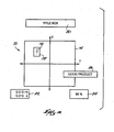
- FIGS. 4 and 5 these drawings illustrate two representative run screens 70 and 72, respectively, that are viewable by an operator of the printing press 10.
- the run screens 70 and 72 may be used to observe print-to-cut and print-to-fold operations. In other embodiment, similar run screens may be utilized to observe web movement for other applications.
- the run screens 70 and 72 include an X-Y axis that includes an acceptable range of operation 74. In one embodiment, the acceptable range 74 is green when the product being produced is considered good product, and the acceptable range 74 is red when the product being produced is considered bad product.
- a cross hair pointer 76 indicates the X-Y coordinates of the pattern or mark being analyzed.
- a standard deviation monitor box 78 illustrates the error typically associated with the algorithm used to analyze the pattern or mark.
- the run screens can be configured to include a title box 80, an error correction amount box 82, a pattern recognition level box 84, and a status box 86.
- the title box 80 may indicate what the run screen is representative of (e.g., ribbon number two of a twenty-four ribbon system).
- the error correction amount box 82 may indicate how far the object is from the origin of the X-Y axis (e.g., pattern is located 0.381 mm (0.015 inches) left of center and 0.381 mm (0.015 inches) above center).
- the error correction amount box 82 simply quantifies the error for the printing press 10 operator.
- the pattern recognition level box 84 may indicate how successful the analysis algorithm currently is recognizing the pattern (e.g., 89% recognition).
- the status box 86 further indicates the status of the product (e.g., good product, bad product).
- the run screens 70 and 72 may be further configured to include fewer or additional functions.
- the present invention can be utilized with other control systems on the printing press 10 and can be utilized when an image of the web 12 is required to be obtained.
Abstract
Description
- The present invention relates generally to the field of printing presses, and specifically to a method and apparatus for visually inspecting images on a substrate moving along a printing press using an image recording assembly comprising an image recording device and light emitting diode ("LED") illumination source.
- In an exemplary printing press such as a web offset press, a web of material, typically paper, is fed from a storage mechanism, such as a reel stand, to one or more printing units that imprint the web with repetitive images- The imprinted web is typically driven through a number of processing units such as a dryer unit, a chill stand, and/or a coating machine. The web is then fed to a former/folder.
- Various conditions of the printing press (e.g., web tension, presence of splices, and influence from folders, slitters, imprinters, gluers, and other processing equipment) may cause the position of the web to vary over time with respect to the processing stations (i.e., printing units, processing units, former/folder, etc.). Accordingly, it is necessary to periodically adjust the positional relationship of the web and the processing stations by advancing or retarding the longitudinal position of the web and/or adjusting the lateral position of the web.
- Control systems that control the adjustment of the positional relationship of the web and the processing stations are generally known, and include cutoff control. Typically, the amount of positional adjustment is determined by observing the movement of the web using a visual inspection system and/or using a printing press operator manually observing the web. Other printing press control systems include color registration, color control and web inspection.
- Existing visual inspection systems that operate in conjunction with control systems typically utilize at least one camera assembly. Camera assemblies typically include an image recording device, such as a charge-coupled device ("CCD") camera. The camera assembles also typically include an illumination system for illuminating the field of view of the image recording device when an image is being recorded. Existing illumination systems include a light source such as a pulsed xenon strobe light and/or an incandescent light.
-
EP 1 215 878 A2 describes an image forming apparatus provided with a single LED light and a CMOS sensor for capturing an image of recording material within the apparatus. The captured image is then used to modify the parameters of a fixing process by which toner is fixed onto the recording material. -
US6,141,046 describes a handheld label barcode reader for illuminating and capturing an digital image of two-dimensional information indicia on the label. The target label is illuminated by a circular LED array mounted behind a lens of a camera. - Generally, each camera assembly used in a visual inspection system is coupled to a dedicated processing unit (i.e., each processing unit accommodates only a single camera assembly) that is thereby coupled to a control system used to control an aspect of the printing press. At least a portion of the control system may be included in the dedicated processing unit. Technical requirements of the existing visual inspection systems generally necessitate that the interconnection that couples a camera assembly to the dedicated processing unit is less than a maximum 4.5 m (fifteen foot) distance. Existing camera assemblies are typically synchronized to the traveling web using a series of shaft encoder. Existing camera assemblies do not include the ability to record every revolution or iteration of the traveling web (i.e., the camera assemblies do not include sampling rates that are high enough to record at least a portion of an image printed on the traveling web), and thus existing camera assemblies rely on sampling techniques to analyze the traveling web for movement. Existing visual inspection systems cannot detect variation in the position of the web in any direction that is not in the same plane as the primary web movement.
- The light sources utilized in the illumination system of existing visual inspection systems generally produce heat that must be dissipated to reduce adverse effects from the heat on the image quality (e.g., reduced image quality due to lens distortion). Additionally, the light sources would preferably use less power, cost less, and last longer.
- According to the present invention, there is provided a camera system configured for optical communication with a substrate moving on a printing press, the substrate having been imprinted with different color inks at a plurality of printing units of the printing press, the camera system comprising: an image recording device configured to record image data of the substrate moving on the printing press; and an illumination system configured to illuminate the field of view of the image recording device, characterized in that the illumination system comprises a plurality of LEDs arranged in a configuration surrounding the image recording device.
- The invention provides a visual inspection system for a printing press that visually inspects a substrate moving on a printing press using, for example, a CMOS based image recording device. The visual inspection system of the present invention provides a higher level of functionality at less expense than existing visual inspection systems. The visual inspection system of the present invention can be implemented in new and existing printing presses to perform visual inspection of the substrate for control systems utilized in a number of different applications, e.g., ribbon or web control including side lay control, print-to-cut control, print-to-fold control, print-to-process control, color registration, color control, web inspection, or any other application where visual inspection of the substrate is desired.
- Other features and advantages of the present invention will become apparent by consideration of the detailed description and accompanying drawings.
-
-
FIG. 1 is a schematic diagram of a representative web offset printing press. -
FIG. 2 is a block diagram of a visual inspection system in accordance with the present invention. -
FIG. 3 is a perspective view of a LED light array encircling the lens of an image recording device. -
FIG. 4 is an exemplary run screen. -
FIG. 5 is an exemplary run screen. - Referring to
FIG. 1 , arepresentative printing press 10 for printing a number of repetitive images upon a substrate such as web 12 (e.g., paper) is illustrated. Theprinting press 10 illustrated is a web offset press that includes a reel stand 14 that supports areel 16 of theweb 12. It should be noted that the invention is equally applicable to sheet fed presses and other non-offset presses such as gravure presses and newspaper presses for example. - The
printing press 10 includesprinting units printing press 10, thefirst printing unit 18 encountered by theweb 12 prints with black ink and theother printing units 20, 22 and 24 print with other colors. For example, the printing unit 20 may print in magenta ink, theprinting unit 22 may print in cyan ink, and the printing unit 24 may print in yellow ink. It should be understood, however, that the invention is capable of being carried out with printing units that print in different colors, and/or with fewer or additional printing units. Theprinting press 10 includes adrive system 26, includingdrive rollers 28, that moves theweb 12 from thereel 16 through each of theprinting units printing units traveling web 12. - Each
printing unit rotatable blanket cylinders web 12. Eachprinting unit plate cylinder 34 which has a printing plate thereon, and which applies an ink image to theblanket cylinder 30. Optionally, if it is desired to print both sides of theweb 12, eachprinting unit plate cylinder 36 which has a printing plate thereon, and which applies an ink image to theblanket cylinder 32. Theblanket cylinders plate cylinders web 12. - After exiting the
printing stations web 12 is guided through various processing units as desired, such as adryer 38, achill stand 40, and acoating machine 42. The web is then fed to a former/folder 44. - Automated web-fed printing presses generally include at least one camera assembly in optical communication with the
web 12. Each camera assembly is utilized to observe the web for a representative control system of the printing press. Theprinting press 10 is coupled to at least one visual inspection system. As illustrated inFIG. 2 , a visual inspection system 46 of the present invention includes a side frame unit 48 (i.e., processing unit) and at least onecamera assembly 50 configured to be in optical communication with theweb 12. The visual inspection system 46 may also include at least one camera assembly positioning unit 52. The combination of acamera assembly 50 and a camera assembly positioning unit 52 is also known as a camera system 54. - A camera assembly positioning unit 52 is not necessary if, for example, a
single camera assembly 50 or a plurality of cooperating cameras assemblies 50 obtain a field of view that covers all required areas of theweb 12. Eachcamera assembly 50 and/or camera system 54 included in the visual inspection system 46 is mounted on theprinting press 10 to obtain a field of view of theweb 12 in an area that requires visual inspection. The visual inspection system 46 allows for future alteration of both the number and the placement ofcamera assemblies 50 and/or camera systems 54. - The
side frame unit 48 includes at least one interconnection to eachcamera assembly 50 used and at least one interconnection to each camera assembly positioning unit 52 used. The interconnections must be less than the maximum distance allowed by the low-voltage differential transmitters and receivers utilized to facilitate the transfer of information. When a non-multiplexed transmission protocol is used for the transfer of information, the interconnection can be approximately 91 m (300 feet). When a multiplexed transmission protocol is used for the transfer of information, the interconnection can be approximately 9 m (30 feet). A non-multiplexed transmission protocol is used in the preferred embodiment. In one embodiment, the cabling used for the interconnections is rated for high frequency transmissions. - A single
side frame unit 48 can preferably accommodate up to, for example, eightcamera assemblies 50 during steady state operation of theprinting press 10. Additionally, theside frame unit 48 can be located up to 305m (1000 feet) fromcontrol systems 56 and decision electronics of theprinting press 10. In one embodiment, theside frame unit 48 is coupled to each of thecontrol systems 56 and the decision electronics via an Ethernet connection. The invention allows for increased flexibility in mounting of the components of the visual inspection system 46 based upon the capacity of theside frame unit 48, the extended distances of the interconnections, and acamera assembly 50, which is reduced in sized compared to existing camera assemblies, based upon the components utilized and the design incorporated. - The
side frame unit 48 may include a single-board computer ("SBC") 58, a power supply 60, and at least one camera interface board ("CIB") 62. Eachcamera interface board 62 is coupled to thesingle board computer 58 via a bus connector located on thesingle board computer 58. Eachcamera interface board 62 can be coupled to either one or a plurality ofcamera assemblies 50. Eachcamera interface board 62 can be coupled to each camera positioning unit 52 that is adapted to move therespective camera assembly 50 coupled to thecamera interface board 62. - The
single board computer 58 may be of a conventional type including a Pentium or higher processor with a clock speed of at least 330 MHz, a personal computer ("PC") architecture, a peripheral component interconnect ("PCI") (i.e., a personal computer bus), approximately 32 MB of memory (semiconductor memory and/or disk drive storage), and an Ethernet port. Optionally, thesingle board computer 58 may include an integrated drive electronics ("IDE") (i.e., hard disk) controller, a video graphics array ("VGA") driver, and a keyboard input. The amount of memory required is predominately a function of the amount of historical data that is stored. If only limited historical data is desired, the memory requirement can be kept low. Thesingle board computer 58 may be configured to allow for remote software uploads and remote system diagnostics. - Each
camera assembly 50 includes animage recording device 64 and preferably an illumination system 66. In the preferred embodiment, theimage recording device 64 is a CMOS based image recording device (e.g., CMOS camera and/or CMOS sensor) such as model MCM 20014 available from Motorola, or other similar devices from other manufactures. Advantages of a CMOS based image recording device include lower power consumption, reduced data transmission requirements, and directly modifiable acquisition parameters on a single integrated chip. - The illumination system 66 includes a light source to illuminate the field of view. In the preferred embodiment, the light source is an LED light array, and more preferably, a plurality of high intensity LEDs. Such LEDs are available as model LXHL-PH01 from LumiLeds, or other similar devices from other manufactures. The
LED light array 67 preferably incorporates a pattern or configuration located around the lens of theimage recording device 64 such as the circular configuration shown inFIG. 3 . However, it should be noted that other configurations or patterns can also be utilized such as a rectangular configuration. The use of a non-strobe and non-incandescent light source, such as the LEDs, generates less heat, costs less, uses less power and has a longer life as compared to strobe and incandescent light sources. However, it should be noted that strobed LEDs and incandescent light sources can be utilized with the present invention - With reference back to
FIG. 2 , the visual inspection system 46 is preferably synchronized with the movement of theweb 12 with asynchronization module 68. Thesynchronization module 68 is coupled to theprinting press 10 such that a transition is detected upon each major revolution of theweb 12 passing by (e.g., a transition is detected for each image repeat). The visual inspection system 46 utilizes the transitions to generate an internal timing that results in recordation of an image of at least a portion of each and every image repeat passing by thecamera assembly 50. - The visual inspection system 46 utilizes at least one
synchronization module 68. Generally, each control aspect of theprinting press 10 that is being monitored includes adedicated synchronization module 68. In an alternative embodiment, the signal from thesynchronization module 68 may be multiplexed together or daisy chained for use by a number of control applications. The present invention allows for synchronization of the visual inspection system 46 with an external stimulus operating at rates in excess of thirty frames per second. Thus, the visual inspection system 46 can record at least a portion of every image repeat passing by acamera assembly 50 on aprinting press 10 running at rates of speed in excess of 1067 m (3500 feet) per minute with a 57 cm (22.5 inch) repeat rate. Additionally, the visual inspection system 46 can synchronize with an external stimulus over a range of rates with the typical range falling between five frames per second and thirty frames per second. - The
synchronization module 68 may include a shaft encoder that contains a top-dead-center ("TDC") indication as well as 1000-8000 divisions indicating minor gradations of position. Alternatively, thesynchronization module 68 may include a shaft encoder that contains only a TDC indication. The preferred embodiment utilizes a shaft encoder that contains only a TDC indication. The TDC only method may allow for almost jitter free indication of the crossing of the next repeat. Both methods divide the time between transitions into enough pieces to allow accurate positioning. The visual inspection system 46 then counts the time from the latest transition and automatically provides a control signal to thecamera assembly 50 indicating the correct time to record the image. - In general operation, the
side frame unit 48 is coupled to the camera assembly positioning units 52 and thecamera assemblies 50 by a number of interconnections (e.g., data buses). Theside frame unit 48 sends control signals to the camera assembly positioning unit 52 which moves thecamera assembly 50 to a position over theweb 12 based on control signals and an encoder input. In one embodiment, the camera assembly positioning unit 52 is configured to move thecamera assembly 50 to any X coordinate within a predetermined area based on the mechanical limitations of the camera assembly positioning unit 52 (e.g., mounting location and length of travel in each direction) and to a Y-coordinate based on the encoder input. Although positioning of thecamera assembly 50 is automatic, positioning can be overridden by an operator of theprinting press 10 if the operator wishes to manually position thecamera assembly 50. It should be noted that eachcamera assembly 50 can also remain stationary relative to the web. - The
side frame unit 48 also sends control signals to theimage recording device 64 and the illumination system 66. When the control signals include a request to acquire an image, theweb 12 is illuminated by the illumination system 66 and theimage recording device 64 simultaneously records image data that is representative of at least a portion of the printed image within the field of view of theimage recording device 64. More specifically, an image of theweb 12 is recorded by first enabling a few of the rows of pixels and exposing their cells to light, and then, after a short time (which is based on the shutter speed of the image recording device 64), an image of those pixels is recorded and the next set of rows is enabled. This process continues until all rows of the requested image are recorded. Theimage recording device 64 can record a representation of at least a portion of theweb 12 within the field of view instead of only a single point or a single line of information as is recorded when using existing image recording devices. - Properties of the
image recording device 64 allow for the start and end X-Y dimensions of the image to be controlled to allow for precise image recordation. If theweb 12 moves so that the start and end X-Y dimensions of the image that is intended to be recorded next cannot include the object of interest (i.e., the object of interest is outside the field of view of the image recording device 64), then thecamera assembly 50 is repositioned by the camera assembly positioning unit 52 as discussed above so the object of interest is within the start and end X-Y dimensions of the image to be recorded. - In one embodiment, the
image recording device 64 is initialized using inter-integrated circuit ("I2C") messaging lines and following an I2C protocol. Various registers in theimage recording device 64 allow for full control of the processes of theimage recording device 64. The registers most often utilized (at times other than initialization) include a shutter speed register, a column gain register, and a window size register. - The window size register allows the size of the image to be set. The size of the image can be set to be all, or any portion thereof, of the field of view of the
image recording device 64. If the size of the image is set to be only a portion of the field of view, the image can be set to occupy any X-Y coordinates of that field of view. However, the size of the image needs to be set to a size sufficient to allow for continuous monitoring of the desired portion of theweb 12 over normal speed variations and synchronization jitter. - The shutter speed register of the
image recording device 64 is set to optimize the image recording at various speeds of theprinting press 10. The shutter speed is fast enough to totally stop motion at rates of speed in excess of 1067 m (3500 feet) per minute (i.e., the web may travel at rates of speed in excess of 1067 m (3500 feet) per minute). Additionally, the shutter speed of the CMOS image recording device is variable to generate exposure times in a range of one micro second to one second. In one embodiment, a single shutter speed setting may be used for a wide range of printing press speeds. - The column gain register of the
image recording device 64 is used to balance color gain for the color temperature of the illumination system 66. As discussed above, dependent upon what type of light source is used, heat generation may cause distortion of the recorded image. Adjustment of the column gain register adjusts for this. TheLED light array 67 generates less heat than existing light sources and therefore reduces correction of any distortion that may occur due to that heat generation. Additionally, the image analysis algorithms used by theside frame unit 56 can further reduce the adverse effects of heat. Values for all of the registers are preloaded at startup and only changes in the register values need to be loaded at run time. The values can be placed in a database for initialization purposes. - After an image is recorded by the
image recording device 64, the recorded image is transferred to theside frame unit 48. Each of the sets of rows of data may be transferred as subsequent rows are being recorded. The recorded image (or part thereof) may be transferred via a direct memory access ("DMA") from theimage recording device 64 to theside frame unit 48, or in another embodiment, theimage recording device 64 and theside frame unit 48 may share a "foreign" memory and the transfer is therefore performed internal to that memory. The amount of image data transferred depends upon the physical size of the recorded image. Theside frame unit 48 may include several megabytes of storage space (i.e., a buffer) reserved for eachcamera assembly 50 coupled thereto. The buffer is used in a circular form so that several recorded images are available to theside frame unit 48 after the first several recorded images are transferred. Once the buffer is full, new image data is saved over the "oldest" image data in the buffer. In one embodiment, the image data may be transferred to other memory after analyzed to allow for future historical analyses. In another embodiment, the size of the buffer may be large enough to allow for the historical analyses. - Once the
side frame unit 48 receives the recorded image, the recorded image is processed according to what control aspect in being analyzed. In the example set forth below, cutoff control in the folder is being controlled. Theside frame unit 48 is able to recognize a pattern of marks (e.g., a diamond, a triangle, or any other pattern) in addition to the single mark and the linear train of marks that existing camera assemblies can recognize. This ability allows the visual inspection system 46 to detect variation in the position of the web in both the lateral and the circumferential directions.Control system 56, cutoff control in this example, can therefore be used to control adjustment of the web in the same plane as, as well as in planes other than, the direction of the primary movement of theweb 12. Additionally, the pattern of marks which the visual inspection system 46 recognizes may be part of the image rather than marks printed on theweb 12 specifically for the purpose of detecting web movement. The ability to recognize parts of the image normally produced reduces problems associated with placement of these special marks on the web (e.g. in a fold or in an area that is to be cut off for waste). - The
side frame unit 48 is configured to analyze a recorded image for consistency and is also configured to determine a position of components of the recorded image to within 0.0254 mm (0.001 of an inch) in both the lateral and the circumferential directions. The analysis techniques may incorporate mathematical and/or geometrical image analysis algorithms. Generally, a number of algorithms can be used in a singleside frame unit 48 to allow for use of the visual inspection system 46 in a number of modes (e.g., initialization, steady state operation, shut down). Using these mode specific algorithms allows the visual inspection system 46 to lock onto a pattern of marks in less than three seconds when theweb 12 is traveling at approximately 91 m (300 feet) per minute atprinting press 10 startup. - In this cutoff control example, the analysis begins by locating light and/or dark transitions in the body of the recorded image. After a pattern of at least three light and/or dark transitions is located, the pattern is compared to prior sets of data to determine if there has been any shift in the traveling web. Any number of sets of marks and/or patterns may be loaded into the
side frame unit 48 for comparison to the marks or patterns from the recorded image. Any shift detected is quantified using the resolution of thesynchronization module 68 information (e.g., TDC transition) and the camera positioning unit 52. Theside frame unit 56 can calculate the X-Y coordinates of the reference mark or pattern by determining how fast theweb 12 is traveling and how much time has passed since the last known X-Y position was determined. Theside frame unit 56 generates an error for each camera assembly it is analyzing and transmits the resulting circumferential and lateral errors to therepresentative control systems 68. This information is then used to control the necessary adjustments to the positional relationship of theweb 12 and the processing stations. - The
side frame unit 48 builds a history of happenings and analyzes that history for patterns of variation in the positional relationship of theweb 12 and the processing stations. If a period for a pattern in the error tracking is determined, theside frame unit 48 is configured to apply these periods to a "look ahead" analysis to provide error correction of projected upcoming events. In another embodiment, data is stored for off-line analysis that may provide insight in how to modify the algorithms to better analyze the image data. These types of analyses increase the overall memory requirements of theside frame unit 48. - In another example, the visual inspection system 46 is utilized in conjunction with a closed-loop ribbon or web control system. Generally, all web up configurations of the former/folder are stored in a memory. Additionally, ribbon control system setup information is also stored in a memory. Such information includes camera mapping (
camera assembly 50 to compensator andcamera assembly 50 to angle bar relationships for all ribbons contained in the setup),synchronization module 68 timing, web widths and locations, and various other information relative to the performance tuning of the ribbon control, system. - At printing press startup, a folder preset system presets the ribbon compensators and angle bars. The ribbon control system's side lay function then moves each ribbon (a system may include between 2 and 24 ribbons) to an exact start position. Movement to the exact start location is accomplished by visually inspecting a specifies edge of each ribbon using the visual inspection system 46. Typically, a
camera assembly 50 is mounted to view each of the ribbons. The visual inspection system 46 locates a mark or pattern and the ribbon control system then calculates the absolute position of the ribbon edge based on the width of the ribbon and the X-Y coordinates of the mark or pattern provided by the visual inspection system 46. As soon as the ink on theweb 12 is stable, thecamera assembly 50 is positioned in the alley where the mark or pattern is to be located. - If the ribbon control system is utilizing mark recognition, the visual inspection system 46 begins to search out the mark by recording images based upon the timing provided by the
synchronization module 68. Once the mark is located, the ribbon control system then adjusts the print-to-cut register and also fine tunes the print-to-fold register. The invention is configured to locate a mark in two plate revolutions providing the ink is visible and the camera assembly is positioned over the alley. - As discussed above, if a pattern recognition in the
web 12 is desired, the present invention is configured to locate a pattern within three seconds of startup of theprinting press 10 if theweb 12 is traveling at a speed of approximately 91 m (300 feet) per minute. - The ribbon control system preferably includes a job configuration library which can be used to call up a job without having to enter all of the setup parameters. If the job is stored in the job configuration library, the
printing press 10 is initialized by selecting a job from the job configuration library, verifying the settings of the job, adjusting the settings if necessary, and placing the system in automatic mode. The visual inspection system 46 then takes over the observation of the web movement when theprinting press 10 is in automatic mode. - If a job that needs to be run is not in the job configuration library, the printing press operator may need to perform numerous tasks including definition of camera mapping, determination of angle bar ribbon wrap direction to establish motor output polarity, determination of compensator ribbon wrap direction to establish motor output polarity, selection of at least one
synchronization module 68 for use, and determination of the ribbon width and offset for each ribbon before theprinting press 10 can be placed into automatic mode. Additional tasks may be required before theprinting press 10 is placed into automatic mode, the number depending upon whether a mark recognition or pattern recognition is utilized. - Turning now to
FIGS. 4 and5 , these drawings illustrate two representative run screens 70 and 72, respectively, that are viewable by an operator of theprinting press 10. The run screens 70 and 72 may be used to observe print-to-cut and print-to-fold operations. In other embodiment, similar run screens may be utilized to observe web movement for other applications. The run screens 70 and 72 include an X-Y axis that includes an acceptable range ofoperation 74. In one embodiment, theacceptable range 74 is green when the product being produced is considered good product, and theacceptable range 74 is red when the product being produced is considered bad product. Across hair pointer 76 indicates the X-Y coordinates of the pattern or mark being analyzed. A standarddeviation monitor box 78 illustrates the error typically associated with the algorithm used to analyze the pattern or mark. The run screens can be configured to include a title box 80, an errorcorrection amount box 82, a patternrecognition level box 84, and astatus box 86. The title box 80 may indicate what the run screen is representative of (e.g., ribbon number two of a twenty-four ribbon system). The errorcorrection amount box 82 may indicate how far the object is from the origin of the X-Y axis (e.g., pattern is located 0.381 mm (0.015 inches) left of center and 0.381 mm (0.015 inches) above center). The errorcorrection amount box 82 simply quantifies the error for theprinting press 10 operator. The patternrecognition level box 84 may indicate how successful the analysis algorithm currently is recognizing the pattern (e.g., 89% recognition). Thestatus box 86 further indicates the status of the product (e.g., good product, bad product). The run screens 70 and 72 may be further configured to include fewer or additional functions. - As previously described, the present invention can be utilized with other control systems on the
printing press 10 and can be utilized when an image of theweb 12 is required to be obtained.
Claims (24)
- A camera system (54) configured for optical communication with a substrate moving on a printing press (10), the substrate halving been imprinted with different color inks at a plurality of printing units of the printing press, the camera system (54) comprising:an images recording device (64) configured to record image data of the substrate moving on the printing press (10); andan illumination system (66) configured to illuminate the field of view of the image recording device (64),characterized in that the illumination system (66) comprises a plurality of LEDs arranged in a configuration surrounding the image recording device (64).
- The camera system (54) of claim 1 wherein the image recording device (64) comprises a CMOS sensor.
- The camera system (54) of claim 1 or 2 wherein the plurality of LEDs is arranged in a circular configuration.
- The camera system (54) of claim 1 or 2 wherein the plurality of LEDs is arranged in a rectangular configuration.
- The camera system (54) of any of claims 1 to 4 wherein the image recording device (64) includes a lens and the plurality of LEDs is arranged in a configuration surrounding the lens.
- A visual inspection system (46) for inspecting a substrate moving on a printing press (10), the substrate having been imprinted with different color inks at a plurality of printing units of the printing press, the visual inspection system (46) comprising.the camera system (54) of any of claims 1 to 5; anda processing unit (48) coupled to the recording device (64), wherein the processing unit (48) is configured to generate an output, andwherein, in use, the output includes information regarding adjustment of the position of the substrate.
- The visual inspection system (46) of claim 6 wherein the plurality of LEDs is an LED light array (67).
- The visual inspection system (46) of claim 6 wherein said illumination system (66) includes a plurality of high intensity LEDs.
- The visual inspection system (46) of claim 6 wherein said position includes the lateral position of the substrate.
- The visual inspection system (46) of claim 6 wherein said position includes the longitudinal position of the substrate.
- A visual inspection system (46) for inspecting a substrate moving on a printing press (10), the substrate having been imprinted with different color inks at a plurality of printing units of the printing press, the visual inspection (46) system comprising:the camera system (54) of any of claims 1 to 5; anda control system (56) coupled to said image recording assembly (50),wherein, in use, the control system (56) uses a recorded image of the moving substrate from the image recording assembly (50) to control operation of the printing press (10).
- The visual inspection system (46) of claim 11 wherein said control system (56) is a cutoff control system.
- The visual inspection system (46) of claim 11 wherein said control system (56) is a color control system.
- The visual inspection system (46) of claim 11 wherein said control system (56) is a color registration control system.
- The visual inspection system (46) of claim 11 wherein said control system (56) is a web inspection control system.
- The visual inspection system (46) of claim 11 wherein, in use, said image recording device (64) is stationary.
- The visual inspection system (46) of claim 11 wherein, in use, said image recording device (64) is fixed relative to the printing press (10).
- A visual inspection system (46) configured to be in optical communication with a web (12) moving on a web offset printing press (10), said visual inspection system (46) comprising:the camera system (54) of any of claims 1 to 5; anda control system (56) coupled to said image recording assembly (50), wherein the control system (56) uses a recorded image from the image recording assembly (50) to control operation of the printing press (10).
- A method of visually inspecting a substrate moving on a printing press (10), the substrate having been imprinted with different color inks at a plurality of printing units of the printing press, the method comprising:illuminating the substrate of the printing press using an illumination system. (66) configured to illuminate the field of view of an image recording device (64) and comprising a plurality of LEDs arranged in a configuration surrounding an image recording device (64);recording at least one image using the image recording device (64), the image recording device (64) being configured to record image data of the moving substrate of the printing press; andgenerating an output.
- The method of claim 19 wherein the moving substrate is illuminated using high intensity LEDs.
- The method of claim 19 and further including controlling an aspect of the printing press in response to said output.
- The method of claim 21 wherein the printing press (10) is a web offset printing press and the moving substrate is a web (12).
- A visual inspection system (46) for inspecting a substrate moving on a printing press (10), said visual inspection system (46) comprising:a plurality of instances of the camera system (54) of any of claims 1 to 5; anda processing unit (56) coupled to each of said instances of the image recording assembly (50) and adapted to process the recorded images.
- The visual inspection system (46) of claim 23 wherein each of said plurality of instances of the camera system (54) is fixed relative to the printing press.
Applications Claiming Priority (3)
| Application Number | Priority Date | Filing Date | Title |
|---|---|---|---|
| US245469 | 1994-05-18 | ||
| US10/245,469 US6867423B2 (en) | 2002-09-17 | 2002-09-17 | Method and apparatus for visually inspecting a substrate on a printing press |
| PCT/US2003/027812 WO2004026578A2 (en) | 2002-09-17 | 2003-09-04 | Method and apparatus for visually inspecting a substrate on a printing press |
Publications (4)
| Publication Number | Publication Date |
|---|---|
| EP1543354A2 EP1543354A2 (en) | 2005-06-22 |
| EP1543354A4 EP1543354A4 (en) | 2008-09-10 |
| EP1543354B1 true EP1543354B1 (en) | 2011-05-04 |
| EP1543354B2 EP1543354B2 (en) | 2017-10-25 |
Family
ID=31992129
Family Applications (1)
| Application Number | Title | Priority Date | Filing Date |
|---|---|---|---|
| EP03754447.5A Expired - Fee Related EP1543354B2 (en) | 2002-09-17 | 2003-09-04 | Method and apparatus for visually inspecting a substrate on a printing press |
Country Status (6)
| Country | Link |
|---|---|
| US (1) | US6867423B2 (en) |
| EP (1) | EP1543354B2 (en) |
| JP (1) | JP2005538874A (en) |
| AU (1) | AU2003272271A1 (en) |
| DE (1) | DE60337017D1 (en) |
| WO (1) | WO2004026578A2 (en) |
Cited By (1)
| Publication number | Priority date | Publication date | Assignee | Title |
|---|---|---|---|---|
| US9142103B2 (en) | 2012-07-03 | 2015-09-22 | Utc Fire & Security Americas Corporation, Inc. | Mass notification alarm and system with programmable color output |
Families Citing this family (15)
| Publication number | Priority date | Publication date | Assignee | Title |
|---|---|---|---|---|
| US20040188644A1 (en) * | 2002-09-17 | 2004-09-30 | Quad/Tech, Inc. | Method and apparatus for visually inspecting a substrate on a printing press |
| US7032508B2 (en) * | 2003-03-21 | 2006-04-25 | Quad/Tech, Inc. | Printing press |
| DE10332211B3 (en) * | 2003-07-16 | 2005-02-10 | Koenig & Bauer Ag | Machine for processing sheets |
| US20050243042A1 (en) * | 2004-07-01 | 2005-11-03 | Shivji Shiraz M | Method and apparatus for LED based display |
| US7593056B2 (en) * | 2004-10-27 | 2009-09-22 | Honeywell International Inc. | Infrared vision illumination enhancement |
| EP1694047B1 (en) * | 2005-02-16 | 2020-03-18 | X-Rite Switzerland GmbH | Lighting system for a colour measuring device |
| US8733249B2 (en) * | 2007-02-20 | 2014-05-27 | Goss International Americas, Inc. | Real-time print product status |
| WO2010039135A1 (en) * | 2008-10-01 | 2010-04-08 | Hewlett-Packard Development Company, L.P. | Camera web support |
| FR2961327B1 (en) * | 2010-06-11 | 2012-07-27 | Goss Int Montataire Sa | PROCESS FOR PROCESSING FLAT PRODUCTS AND CORRESPONDING DEVICE |
| CN103317842B (en) * | 2012-03-21 | 2015-08-26 | 潮州市彩达包装机械有限公司 | A kind of LED Simultaneous Monitoring instrument for printing |
| DE102015116854A1 (en) * | 2015-10-05 | 2017-04-06 | Manroland Web Systems Gmbh | Method for regulating the web position |
| MX2019000614A (en) | 2016-07-20 | 2019-07-04 | Ball Corp | System and method for aligning an inker of a decorator. |
| US11034145B2 (en) | 2016-07-20 | 2021-06-15 | Ball Corporation | System and method for monitoring and adjusting a decorator for containers |
| CA3088534C (en) | 2018-01-19 | 2023-03-14 | Ball Corporation | System and method for monitoring and adjusting a decorator for containers |
| EP3599094B1 (en) | 2018-07-24 | 2024-05-08 | Dover Europe Sàrl | Visual verification system and method |
Family Cites Families (27)
| Publication number | Priority date | Publication date | Assignee | Title |
|---|---|---|---|---|
| DE3578768D1 (en) | 1985-03-14 | 1990-08-23 | Toppan Printing Co Ltd | DEVICE FOR CHECKING PRINTING. |
| US4882764A (en) | 1985-03-29 | 1989-11-21 | Quad/Tech, Inc. | Cutoff control system |
| CA1305235C (en) | 1986-10-31 | 1992-07-14 | Bruce A. Reynolds | Cutoff control system |
| US5604821A (en) | 1992-02-28 | 1997-02-18 | The University Of South Florida | Structure and method for dynamic scene analysis |
| US5331394A (en) | 1992-04-10 | 1994-07-19 | Metaphase Corporation | Automated lensometer |
| ES2143084T3 (en) * | 1994-10-25 | 2000-05-01 | United Parcel Service Inc | AUTOMATIC ELECTRONIC CAMERA FOR THE CAPTURE OF IMAGES OF LABELS. |
| US5724259A (en) | 1995-05-04 | 1998-03-03 | Quad/Tech, Inc. | System and method for monitoring color in a printing press |
| JPH0996610A (en) * | 1995-09-30 | 1997-04-08 | Tani Denki Kogyo Kk | Illuminating apparatus for visual inspection and its manufacture |
| US6133954A (en) | 1996-03-14 | 2000-10-17 | Tritech Microelectronics, Ltd. | Integrated circuit color chip with cells with integral color filters including triplets of photodiodes with each having integrated therewith transistors for reading from and writing to the photodiode and methods of manufacture and operation thereof |
| US5650864A (en) * | 1996-04-08 | 1997-07-22 | Scanvision | Full color single-sensor-array contact image sensor (CIS) using advanced signal processing techniques |
| US6035077A (en) | 1996-05-03 | 2000-03-07 | Omnivision Technologies, Inc. | Single-chip color CMOS image sensor with two or more line reading structure and high-sensitivity interlace color structure |
| US5777878A (en) * | 1996-06-04 | 1998-07-07 | Preco Industries, Inc. | Screen printing press having longitudinal, lateral and angular screen frame registration system and method |
| US5969750A (en) | 1996-09-04 | 1999-10-19 | Winbcnd Electronics Corporation | Moving picture camera with universal serial bus interface |
| US6002432A (en) | 1996-09-10 | 1999-12-14 | Foveon, Inc. | Method for operating an active pixel sensor cell that reduces noise in the photo information extracted from the cell |
| GB2317522B (en) | 1996-09-12 | 2000-09-27 | Vsli Vision Limited | Low noise operation of an image sensor |
| US6064759A (en) | 1996-11-08 | 2000-05-16 | Buckley; B. Shawn | Computer aided inspection machine |
| US6115066A (en) | 1997-06-12 | 2000-09-05 | International Business Machines Corporation | Image sensor with direct digital correlated sampling |
| US6618084B1 (en) * | 1997-11-05 | 2003-09-09 | Stmicroelectronics, Inc. | Pixel correction system and method for CMOS imagers |
| US6127697A (en) | 1997-11-14 | 2000-10-03 | Eastman Kodak Company | CMOS image sensor |
| US6067421A (en) | 1998-01-16 | 2000-05-23 | Ricoh Company, Ltd. | Camera focus adjusting device for moving an imaging unit |
| US6111245A (en) | 1998-04-22 | 2000-08-29 | National Science Council Of Republic Of China | Low voltage reverse bias arrangement for an active pixel sensor |
| JP2891696B1 (en) | 1998-04-23 | 1999-05-17 | 株式会社東京機械製作所 | Print image inspection device |
| US6101287A (en) | 1998-05-27 | 2000-08-08 | Intel Corporation | Dark frame subtraction |
| ES2209864T3 (en) * | 1999-04-30 | 2004-07-01 | MAHLO GMBH & CO. KG | PROCEDURE FOR THE DETERMINATION OF THE STRETCH ANGLE OF A TEXTILE AND DEVICE BAND FOR THE PERFORMANCE OF THIS PROCEDURE. |
| GB2361765A (en) * | 2000-04-28 | 2001-10-31 | Ncr Int Inc | Media validation by diffusely reflected light |
| JP4428855B2 (en) * | 2000-12-12 | 2010-03-10 | キヤノン株式会社 | Image forming apparatus |
| US6750466B2 (en) | 2001-02-09 | 2004-06-15 | Wintriss Engineering Corporation | Web inspection system |
-
2002
- 2002-09-17 US US10/245,469 patent/US6867423B2/en not_active Expired - Lifetime
-
2003
- 2003-09-04 DE DE60337017T patent/DE60337017D1/en not_active Expired - Lifetime
- 2003-09-04 AU AU2003272271A patent/AU2003272271A1/en not_active Abandoned
- 2003-09-04 WO PCT/US2003/027812 patent/WO2004026578A2/en active Application Filing
- 2003-09-04 EP EP03754447.5A patent/EP1543354B2/en not_active Expired - Fee Related
- 2003-09-04 JP JP2004537729A patent/JP2005538874A/en active Pending
Cited By (1)
| Publication number | Priority date | Publication date | Assignee | Title |
|---|---|---|---|---|
| US9142103B2 (en) | 2012-07-03 | 2015-09-22 | Utc Fire & Security Americas Corporation, Inc. | Mass notification alarm and system with programmable color output |
Also Published As
| Publication number | Publication date |
|---|---|
| EP1543354A2 (en) | 2005-06-22 |
| JP2005538874A (en) | 2005-12-22 |
| AU2003272271A8 (en) | 2004-04-08 |
| DE60337017D1 (en) | 2011-06-16 |
| WO2004026578A3 (en) | 2004-06-10 |
| US20040051061A1 (en) | 2004-03-18 |
| EP1543354B2 (en) | 2017-10-25 |
| EP1543354A4 (en) | 2008-09-10 |
| US6867423B2 (en) | 2005-03-15 |
| WO2004026578A2 (en) | 2004-04-01 |
| AU2003272271A1 (en) | 2004-04-08 |
Similar Documents
| Publication | Publication Date | Title |
|---|---|---|
| EP1543354B1 (en) | Method and apparatus for visually inspecting a substrate on a printing press | |
| EP1584471B1 (en) | Method and apparatus for visually insepecting a substrate on a printing press | |
| US7477420B2 (en) | Barless closed loop color control | |
| US7187472B2 (en) | Active color control for a printing press | |
| US8132887B2 (en) | Universal closed loop color control | |
| CN100395107C (en) | System for inspecting a printed image | |
| CN100493909C (en) | Devices for controlling at least one rule in a printing machine | |
| US7013803B2 (en) | Color registration control system for a printing press | |
| CA2354434A1 (en) | Process and apparatus for the printing of digital image information | |
| EP0860277B1 (en) | A system and method for registration control on-press during press set-up and printing | |
| CA1230412A (en) | Closed loop register control | |
| US4736680A (en) | Closed loop register control | |
| JPH05269978A (en) | Detection apparatus for error of register allocated to rotary press | |
| EP1472091B1 (en) | Color registration control method for a printing press | |
| US7253929B2 (en) | Camera assembly for a printing press | |
| WO1995031333A1 (en) | General control for multiple color press devices | |
| US20030147090A1 (en) | Camera assembly for a printing press |
Legal Events
| Date | Code | Title | Description |
|---|---|---|---|
| PUAI | Public reference made under article 153(3) epc to a published international application that has entered the european phase |
Free format text: ORIGINAL CODE: 0009012 |
|
| 17P | Request for examination filed |
Effective date: 20050218 |
|
| AK | Designated contracting states |
Kind code of ref document: A2 Designated state(s): AT BE BG CH CY CZ DE DK EE ES FI FR GB GR HU IE IT LI LU MC NL PT RO SE SI SK TR |
|
| AX | Request for extension of the european patent |
Extension state: AL LT LV MK |
|
| DAX | Request for extension of the european patent (deleted) | ||
| RBV | Designated contracting states (corrected) |
Designated state(s): DE FR GB IT |
|
| A4 | Supplementary search report drawn up and despatched |
Effective date: 20080808 |
|
| 17Q | First examination report despatched |
Effective date: 20081111 |
|
| GRAP | Despatch of communication of intention to grant a patent |
Free format text: ORIGINAL CODE: EPIDOSNIGR1 |
|
| GRAS | Grant fee paid |
Free format text: ORIGINAL CODE: EPIDOSNIGR3 |
|
| GRAA | (expected) grant |
Free format text: ORIGINAL CODE: 0009210 |
|
| AK | Designated contracting states |
Kind code of ref document: B1 Designated state(s): DE FR GB IT |
|
| REG | Reference to a national code |
Ref country code: GB Ref legal event code: FG4D |
|
| REF | Corresponds to: |
Ref document number: 60337017 Country of ref document: DE Date of ref document: 20110616 Kind code of ref document: P |
|
| REG | Reference to a national code |
Ref country code: DE Ref legal event code: R096 Ref document number: 60337017 Country of ref document: DE Effective date: 20110616 |
|
| PLBI | Opposition filed |
Free format text: ORIGINAL CODE: 0009260 |
|
| PLAX | Notice of opposition and request to file observation + time limit sent |
Free format text: ORIGINAL CODE: EPIDOSNOBS2 |
|
| 26 | Opposition filed |
Opponent name: MANROLAND WEB SYSTEMS GMBH Effective date: 20120206 |
|
| REG | Reference to a national code |
Ref country code: DE Ref legal event code: R026 Ref document number: 60337017 Country of ref document: DE Effective date: 20120206 |
|
| PG25 | Lapsed in a contracting state [announced via postgrant information from national office to epo] |
Ref country code: IT Free format text: LAPSE BECAUSE OF FAILURE TO SUBMIT A TRANSLATION OF THE DESCRIPTION OR TO PAY THE FEE WITHIN THE PRESCRIBED TIME-LIMIT Effective date: 20110504 |
|
| REG | Reference to a national code |
Ref country code: FR Ref legal event code: ST Effective date: 20120531 |
|
| PLAF | Information modified related to communication of a notice of opposition and request to file observations + time limit |
Free format text: ORIGINAL CODE: EPIDOSCOBS2 |
|
| PG25 | Lapsed in a contracting state [announced via postgrant information from national office to epo] |
Ref country code: DE Free format text: LAPSE BECAUSE OF NON-PAYMENT OF DUE FEES Effective date: 20120403 |
|
| REG | Reference to a national code |
Ref country code: DE Ref legal event code: R119 Ref document number: 60337017 Country of ref document: DE Effective date: 20120403 |
|
| PG25 | Lapsed in a contracting state [announced via postgrant information from national office to epo] |
Ref country code: FR Free format text: LAPSE BECAUSE OF NON-PAYMENT OF DUE FEES Effective date: 20110930 |
|
| PLBB | Reply of patent proprietor to notice(s) of opposition received |
Free format text: ORIGINAL CODE: EPIDOSNOBS3 |
|
| REG | Reference to a national code |
Ref country code: DE Ref legal event code: R073 Ref document number: 60337017 Country of ref document: DE |
|
| REG | Reference to a national code |
Ref country code: DE Ref legal event code: R073 Ref document number: 60337017 Country of ref document: DE |
|
| REG | Reference to a national code |
Ref country code: DE Ref legal event code: R074 Ref document number: 60337017 Country of ref document: DE |
|
| PGRI | Patent reinstated in contracting state [announced from national office to epo] |
Ref country code: DE Effective date: 20130322 |
|
| REG | Reference to a national code |
Ref country code: DE Ref legal event code: R074 Ref document number: 60337017 Country of ref document: DE Effective date: 20130322 Ref country code: DE Ref legal event code: R074 Ref document number: 60337017 Country of ref document: DE Effective date: 20130325 |
|
| GBPC | Gb: european patent ceased through non-payment of renewal fee |
Effective date: 20120904 |
|
| PG25 | Lapsed in a contracting state [announced via postgrant information from national office to epo] |
Ref country code: GB Free format text: LAPSE BECAUSE OF NON-PAYMENT OF DUE FEES Effective date: 20120904 |
|
| PUAH | Patent maintained in amended form |
Free format text: ORIGINAL CODE: 0009272 |
|
| STAA | Information on the status of an ep patent application or granted ep patent |
Free format text: STATUS: PATENT MAINTAINED AS AMENDED |
|
| 27A | Patent maintained in amended form |
Effective date: 20171025 |
|
| AK | Designated contracting states |
Kind code of ref document: B2 Designated state(s): DE FR GB IT |
|
| REG | Reference to a national code |
Ref country code: DE Ref legal event code: R102 Ref document number: 60337017 Country of ref document: DE |
|
| PGFP | Annual fee paid to national office [announced via postgrant information from national office to epo] |
Ref country code: DE Payment date: 20200909 Year of fee payment: 18 |
|
| REG | Reference to a national code |
Ref country code: DE Ref legal event code: R119 Ref document number: 60337017 Country of ref document: DE |
|
| PG25 | Lapsed in a contracting state [announced via postgrant information from national office to epo] |
Ref country code: DE Free format text: LAPSE BECAUSE OF NON-PAYMENT OF DUE FEES Effective date: 20220401 |