EP1542151B1 - Method and apparatus for the electronic capture of rolled fingerprints - Google Patents
Method and apparatus for the electronic capture of rolled fingerprints Download PDFInfo
- Publication number
- EP1542151B1 EP1542151B1 EP04029189A EP04029189A EP1542151B1 EP 1542151 B1 EP1542151 B1 EP 1542151B1 EP 04029189 A EP04029189 A EP 04029189A EP 04029189 A EP04029189 A EP 04029189A EP 1542151 B1 EP1542151 B1 EP 1542151B1
- Authority
- EP
- European Patent Office
- Prior art keywords
- image
- enclosing
- images
- finger
- recording
- Prior art date
- Legal status (The legal status is an assumption and is not a legal conclusion. Google has not performed a legal analysis and makes no representation as to the accuracy of the status listed.)
- Active
Links
- 238000000034 method Methods 0.000 title claims abstract description 71
- 238000005096 rolling process Methods 0.000 claims abstract description 72
- 230000033001 locomotion Effects 0.000 claims abstract description 52
- 230000008859 change Effects 0.000 claims description 20
- 238000004364 calculation method Methods 0.000 claims description 17
- 238000012545 processing Methods 0.000 claims description 15
- 230000006870 function Effects 0.000 claims description 12
- 238000004422 calculation algorithm Methods 0.000 claims description 11
- 238000009826 distribution Methods 0.000 claims description 10
- 230000005693 optoelectronics Effects 0.000 claims description 10
- 230000005540 biological transmission Effects 0.000 claims description 7
- 230000001965 increasing effect Effects 0.000 claims description 7
- 230000036961 partial effect Effects 0.000 claims description 5
- 238000011156 evaluation Methods 0.000 claims description 4
- 230000002123 temporal effect Effects 0.000 claims description 3
- 238000012432 intermediate storage Methods 0.000 claims description 2
- 238000012546 transfer Methods 0.000 claims description 2
- 230000000694 effects Effects 0.000 claims 1
- 238000003384 imaging method Methods 0.000 abstract description 8
- 238000001514 detection method Methods 0.000 description 18
- 230000001133 acceleration Effects 0.000 description 17
- 230000005484 gravity Effects 0.000 description 14
- 230000008569 process Effects 0.000 description 13
- 239000000203 mixture Substances 0.000 description 12
- 239000007787 solid Substances 0.000 description 7
- 238000000926 separation method Methods 0.000 description 6
- 238000007792 addition Methods 0.000 description 5
- 238000005516 engineering process Methods 0.000 description 5
- 239000011159 matrix material Substances 0.000 description 4
- 230000002829 reductive effect Effects 0.000 description 4
- 239000002131 composite material Substances 0.000 description 3
- 239000011521 glass Substances 0.000 description 3
- 230000000670 limiting effect Effects 0.000 description 3
- 238000005192 partition Methods 0.000 description 3
- 238000013138 pruning Methods 0.000 description 3
- 238000005070 sampling Methods 0.000 description 3
- 230000007704 transition Effects 0.000 description 3
- 238000003491 array Methods 0.000 description 2
- 238000006073 displacement reaction Methods 0.000 description 2
- 238000005286 illumination Methods 0.000 description 2
- 230000010354 integration Effects 0.000 description 2
- 238000004519 manufacturing process Methods 0.000 description 2
- 238000001454 recorded image Methods 0.000 description 2
- 239000004065 semiconductor Substances 0.000 description 2
- 239000007858 starting material Substances 0.000 description 2
- 238000002604 ultrasonography Methods 0.000 description 2
- 241001136792 Alle Species 0.000 description 1
- 230000006978 adaptation Effects 0.000 description 1
- 238000004458 analytical method Methods 0.000 description 1
- 230000008901 benefit Effects 0.000 description 1
- 230000003139 buffering effect Effects 0.000 description 1
- 238000004891 communication Methods 0.000 description 1
- 230000008878 coupling Effects 0.000 description 1
- 238000010168 coupling process Methods 0.000 description 1
- 238000005859 coupling reaction Methods 0.000 description 1
- 238000013500 data storage Methods 0.000 description 1
- 238000004090 dissolution Methods 0.000 description 1
- 230000002500 effect on skin Effects 0.000 description 1
- 238000009432 framing Methods 0.000 description 1
- 230000001939 inductive effect Effects 0.000 description 1
- 238000011835 investigation Methods 0.000 description 1
- 238000012544 monitoring process Methods 0.000 description 1
- 238000003909 pattern recognition Methods 0.000 description 1
- 230000000717 retained effect Effects 0.000 description 1
- 230000002441 reversible effect Effects 0.000 description 1
- 238000012502 risk assessment Methods 0.000 description 1
- 231100000241 scar Toxicity 0.000 description 1
- 230000035945 sensitivity Effects 0.000 description 1
- 238000003860 storage Methods 0.000 description 1
- 235000012976 tarts Nutrition 0.000 description 1
- 238000012360 testing method Methods 0.000 description 1
- 238000012795 verification Methods 0.000 description 1
- 238000012800 visualization Methods 0.000 description 1
Images


Classifications
-
- G—PHYSICS
- G06—COMPUTING; CALCULATING OR COUNTING
- G06V—IMAGE OR VIDEO RECOGNITION OR UNDERSTANDING
- G06V40/00—Recognition of biometric, human-related or animal-related patterns in image or video data
- G06V40/10—Human or animal bodies, e.g. vehicle occupants or pedestrians; Body parts, e.g. hands
- G06V40/12—Fingerprints or palmprints
- G06V40/1335—Combining adjacent partial images (e.g. slices) to create a composite input or reference pattern; Tracking a sweeping finger movement
Definitions
- the invention relates to a method and an arrangement for the electronic recording of a moving object, in particular for receiving a finger which has been unrolled on a support surface.
- the invention finds primarily application for the production of electronic fingerprints, but can also be used to advantage in object tracking for the intelligent control of a variable in position and / or size sampling window.
- the background for the use of fingerprints in forensics is the uniqueness of the dermal scar images, which are not inheritable and which are immutable from the fourth embryonic month to dissolution after death.
- the image template can be the finger itself, a fingerprint applied to paper by ink or a trace photogram. The latter two techniques were and are mainly used by the police. With the help of pattern recognition techniques capable of extracting the characteristics of a fingerprint, it is possible to automate the identification and verification of fingerprints.
- the above-mentioned techniques have increasingly been integrated into electronic systems that allow the finger to be picked up directly. This shortens the recording and evaluation time, which at the same time improves the quality of the images. If a finger has not been detected correctly, it is possible to immediately repeat the process of recording that one finger.
- the electronic image capture of fingerprints is usually done with matrix or line sensors based on CCD or CMOS technology.
- the fingerprint is converted as an image template by special optics and sensors in an electronic image and then digitized, creating a raster image with a fixed spatial and gray scale resolution.
- capacitive, thermal, ultrasound-based or pressure-sensitive sensors can also be used to record electronic fingerprints.
- the causes for the loss of information are due not only to the deformation of the finger and the resulting changes at two different points in time, especially in too little temporal scanning of the finger by the image acquisition unit. That is, to ensure that a finger is picked up correctly, the image acquisition unit must have a minimum frame rate, depending on the method of assembly used, so that disturbing processes, such as twisting or slipping during the rolling process of the finger, can be detected.
- the frames coming from the imaging unit have a fixed size and are based on a fixed time regime (dictated by a clock generator or an event trigger).
- the unwinding speed (and possibly its change) as well as the size of the finger contact surface (and its real change in the unrolling process) can not be taken into account in the readout regime of the image pickup unit.
- two neighboring fingerprint strips must have a sufficiently large intersection for the respective method. This can only be achieved if a fast time sampling occurs when rolling the finger. This is currently being realized by sensors with a high image read rate (frame rate) of more than 25 frames / second (B / s).
- the invention is therefore based on the object to find a new way to electronically record unrolled fingerprints, the high-resolution frames and a tight sequence of images for seamless composition of the individual images to an overall picture without resorting to expensive image sensors with high frame rate (read speed) got to.
- the object is achieved in a method for the electronic recording of a moving object, in particular for recording a finger unrolled on a recording surface, wherein the object is detected with its structures during movement by means of a spatially resolving image recording unit in a sequence of individual images and processed as a two-dimensional electronic image , is achieved by determining from the position and size of the object in at least one of the individual images read out of the image recording unit a figure enclosing the object, that from the enclosing figure rectangle magnified by tolerance additions aligned parallel to the row and column direction of the sensor, and that the enlarged rectangle is used to predict and adjust the size and location of an active pixel area of the image acquisition unit for at least one subsequently read image, such that the read active pixel range of the image pickup unit due to its adaptation always kept small and a higher frame rate in the sensor reading or data transmission is realized.
- the enclosing figure of the object image of the currently scanned image is determined by a respective gradient image formed in the column and in the row direction, a difference of adjacent gray values in the row or in the column direction being formed for the generation of the gradient image for each pixel.
- the pixels of each gradient image are preferably formed from the difference between the gray values of the preceding and succeeding pixel of the currently examined pixel of the rows or columns.
- start and end values of the enclosing figure of the object image are advantageously determined from at least one gradient image of the rows or columns aligned in the direction of the object movement, a first and a last significant difference of adjacent gray values per row or column Calculation of the start and end values of the figure enclosing the object is determined.
- the significant differences are expediently determined by exceeding threshold values. It proves advantageous to calculate an average value or a median value of the start and end values determined from the gradient image in at least one dimension which corresponds to the main movement direction of the object, the mean or median values then being linear boundaries of the object image being rectangular form enclosing figure.
- the start and end values are entered into a location histogram at least from the gradient image that corresponds to the main movement direction of the object, the locations at which the integral frequency distribution reaches a significant threshold form the boundaries of a figure enclosing the object image in a rectangular manner ,
- This threshold value can make sense 5% of the integral frequency distribution.
- it is also possible to choose the maximum value of the frequency distribution To save on computational and storage capacity, it is advantageous to use only the start and end values of selected rows or columns of the gradient image for determining the boundaries of the rectangular enclosing figure.
- a tolerance addition for generating the enlarged rectangle is determined differently depending on a detected movement sequence of the object, wherein from the at least two previously read images after determining the boundaries of the respective enclosing figure different evaluation algorithms based on the temporal Changing the boundaries of the enclosing figure can be applied in the successive pictures.
- roll-over trace routine is at the heart of the image capture of a rolled-up finger to provide a complete, high-resolution series of individual images for the composition of the complete footprint of a rolled-up finger
- roll-off tracking is conveniently accomplished by a roll-off detection that is in place Number of progressions in the same direction shifts the boundaries of the enclosing figure, the motion tracking switches to the roll tracking, initiated and terminated by a AbrollParkung, which terminates the Abrollv adoptedung at a reversal of direction of movement of the boundaries of the surrounding figure.
- an intermediate storage of all images used for the start detection is advantageously carried out within the Abrollstarterkennung to keep the already read images for the subsequent complete composition of the unrolled finger available.
- the object of the invention in an arrangement for electronically recording a moving object, in particular for recording a finger unrolled on a recording surface, with an image recording unit for recording a sequence of two-dimensional individual images of a moving object, wherein the composition of an overall image of the moving object Individual images have local overlaps, according to the invention solved in that the image pickup unit a logic unit for the current calculation of a a limited pixel area, which encloses the object image closely, on the basis of at least one image previously read by the image acquisition unit, in that the logic unit is assigned a program memory, a data memory, a processor and an interface, the processor being provided for controlling the data flows, and in that the interface for data transfer of the images, which are controlled in a defined manner by the logic unit with respect to size and position of their pixel area, is present on an external computer unit, wherein the computer unit contains the image processing for assembling the temporally successively recorded images into an overall image.
- the image acquisition unit preferably has an optoelectronic sensor, but may also be equipped with a capacitive, inductive, thermal, ultrasonic or other type of contact sensor.
- Suitable optoelectronic image sensors are CCD arrays or CMOS arrays (each in the form of a matrix or line array).
- the image acquisition unit can also contain a sensor with a low frame rate ( ⁇ 25 B / s), in which the low frame rate is based only on the reading of all pixels of the sensor, but the reading of images from an arbitrarily programmable active pixel area with a much larger frame rate is feasible.
- the image acquisition unit preferably has a large-area sensor in which a complete footprint or handprint with high resolution but low frame rate can be realized by a single sensor reading, in which a defined partial area of the receiving surface is defined for receiving individual unrolled fingers is, wherein the sensor in a correspondingly limited active pixel area, which is assigned to the defined portion of the receiving area for the unrolling finger, for reading pixelreduced images is controllable, so that the frame rate for recording unrolled fingerprints compared to foot or hand prints significantly increased becomes.
- the image acquisition unit may also be a high-frame-rate sensor ( ⁇ 25 B / s) in which the interface is the limiting element of data transmission, so that only a small portion of the image data can be transmitted in "real time" ,
- the readout of data-reduced images according to the invention takes place from arbitrarily accessible pixel areas of the data memory in order subsequently to increase the data rate of the transmission via the interface.
- the method according to the invention for determining the boundaries of the active pixel area advantageously takes place in a logic unit (hardware) which precedes (the arithmetic unit for assembling the images of the object) and which is expediently an FPGA (freely programmable gate array).
- the logic unit can also be a PLD (programmable logic element) or an ASIC (application-specific integrated circuit).
- the processor used to control the processes and data streams of the logic unit may advantageously be a microprocessor (MPU), a digital signal processor (DSP) or a microcontroller (MCU).
- the processor can also be integrated directly into the logic unit, the program memory or the external computer unit.
- the invention is based on the basic idea of a gray scale image of variable surface area and / or structure that can be represented as function G (x, y), in which x and y are the coordinates of a respective pixel of the image and G records its gray values electronically.
- a moving object having such an image characteristic is picked up at different times t n sequentially with t n + 1 > t n having different views as a function G n to form the overall image G from images G n (x, y), from the image pickup unit only portions of interest of the object surface are recorded whose size varies depending on the rotational speed of the object.
- the essence of the method according to the invention consists in defining or predicting from each currently read-out image, in each case for the next image, an adapted limited pixel detail which, with the necessary certainty, completely contains the fingerprint to be detected and is set as the read-out window of the image acquisition unit, by the read-out rate (Frame rate) the Increase image acquisition unit.
- the read-out rate Fre rate
- WOI Window of Interest
- the invention it is possible to realize an electronic recording of unrolled fingerprints, which generates the high resolution images adapted to the object size and movement in close succession and allows their reliable composition of the images to the overall image without the need for expensive image sensors or interfaces with high Frame rate must be used.
- the invention allows to choose the frame rate much higher than is possible with the currently used high-resolution sensors or image processing interfaces with complete reading of the image area.
- due to the electronic adjustment of the sensor readout window applications such as taking a complete hand and rolling a finger with one and the same device are possible.
- Fig. 1 is the basic principle of the method for electronically recording an imprint image (hereinafter: fingerprint 11) from the surface of a finger 1 shown.
- the method is based on having a finger 1 sequentially at different times in different, overlapping views is added to subsequently - which is not the subject of the invention - to put together an overall picture of the unrolled finger 1.
- the finger surface Due to the above-mentioned "roll-off rule" for the finger 1, the finger surface can be picked up by the image pickup unit 2 only piecemeal as a successive series of frames.
- the size and position of the recorded images 31 in this case vary depending on the current impression surface and the unwinding speed of the finger 1.
- a complex control method is proposed to function of the current footprint and the unwinding of the finger 1 a suitably restricted section in the reading of the Imaging unit 2 set and monitor, so that high frame rates can be achieved without having to resort to expensive image sensors.
- an image pickup unit 2 which can be read out, for example, at 25 B / s, takes 75 pictures during a rolling process of 3 s duration. Each of these 75 images is a full image containing the fingerprint 11 at a defined time in a particular location (size and position).
- This information loss increases as the unwinding speed of the finger 1 increases relative to the frame rate of the image pickup unit 2.
- the image acquisition unit 2 has to fulfill a minimum image rate for assembly so that, for example, processes such as twisting or slipping during the rolling process can be detected and corrected.
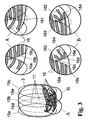
- FIG Fig. 2 in the left partial view the result of an overall picture 3 of a rolled-out finger 1 is stylized, as it occurs when rolling the finger 1 with ink on paper and how it is to be generated as an overall image 3 by composing a sequence of individual images.
- the overall image 3 is to be assembled according to the detail images of a finger 1 of three images per time interval shown in the upper right row, wherein according to the prior art, a series of three snapshots of the finger 1 are scanned as a frame of the entire image acquisition unit 2 in a fixed time regime , Thereafter, information-bearing image parts are extracted, whereby the three image strips 12a to 12c are formed. If the time interval between the snapshots is too long (ie, the frame rate of the image pickup unit 2 is too low) compared to the movement of the finger 1, then, when the overall image 3 is assembled, even if the overlapping of the edge areas of the image strips 12a to 12c occurs, overlapping problems arise if the overlay Finger 1 was additionally laterally shifted or rotated within the rolling motion.
- the two upper papillary lines 13 and 14 have performed a translational movement and the uppermost papillary line 13 has additionally experienced a rotational movement.
- the first segment 131 of the upper papillary line 13 from the strip 12a is closer to the third segment 143 of the next papillary line 14 than the associated second segment 132 of the upper papillary line 13 from the strip 12b. This can lead to the incorrect assembly of at least the papillary lines 13 and 14 in the overall image 3 and thus to misinterpretations of the structures of the unrolled finger 1.
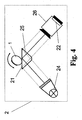
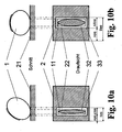
- the image pickup unit 2 consists of a diffuse illumination unit 24, a prism 25 and a camera 26 with an imaging optics and an optoelectronic sensor 22.
- the base surface of the prism 25 is the actual recording surface 21.
- the light is transmitted through the illumination unit 24 is coupled into the prism 25 in such a way that it is totally reflected on the base surface without an applied finger 1, ie if the limit angle for total reflection (here glass / air) is exceeded.
- a brightly illuminated image is generated by means of the imaging optics on the sensor 22 in the camera 26.
- a finger 1 is placed on the prism 25, changes at the points where the finger 1 rests, the transition glass / air to glass / skin. Since the skin has a higher refractive index than air, the critical angle of total reflection is greater. The total reflection is thus canceled at these points and the light is decoupled.
- the sensor 22 which is arranged in the camera 26, the finger 1 is therefore imaged as an image in black and white transitions. The sensor 22 converts these light intensities into electrical signals which are subsequently digitized, as a result of which a raster image with a defined spatial and grayscale resolution is produced.
- the optoelectronic image recording of fingerprints 11 takes place - without limiting the generality - with matrix or line sensors based on CCD or CMOS technology.
- Fig. 4 For simplicity's sake, and not limited to the image pickup principle described above, only the pickup surface 21 and the image pickup unit 2 will be referred to, the unrolled finger being referred to hereinafter as the base of the prism 25 1 in the image pickup unit 2 in any manner in an electronic image converted and output digitized. It is also possible to take fingerprints 11 instead of an opto-electronic sensor 22 to equivalently use capacitive, pressure-sensitive, ultrasound-based or thermal sensors within a suitably designed image pickup unit.
- the inventive method preferably in hardware in an arrangement according to Fig. 5 is realized, takes into account different object surfaces and speeds and thus ensures an optimally adapted scanning of the moving object.
- Starting point of the procedure - as in Fig. 1 displayed - is an (arbitrary) information that tells you that a rolling process should take place.
- This information is usually transmitted by an external computer unit 4, which processes the recorded data.
- the information can also be specified by another external system, with the arrangement according to Fig. 5 communicatively communicates via the interface. Through this sent Information knows the arrangement that a finger 1 will soon be launched and initiates corresponding detection steps. With this active circuit, the following detection steps of the method can take place.
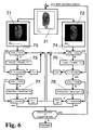
- the task of the PR routine 61 is to check in each image 31 supplied by the image acquisition unit 2 whether a valid fingerprint 11 is present on the support surface 21 or not.
- an x-gradient image 71 and a y-gradient image 72 are generated from each image 31 by forming differences of adjacent gray-scale pixels in each line or column.
- Figure 6 a possible program sequence for recognizing a "valid fingerprint" is shown, this program sequence in each case referring to a single image 31 within an image sequence.
- a gradient image 71 in the x-direction with the values Dx i, j and a gradient image 72 in the y-direction with Dy i, j are formed, in each line or each column differences 73 and 74 are formed from the recorded adjacent gray value pixels. It is possible for each pixel of the gradient image 71 to be generated currently within the rows to form the difference 73 from the direct predecessor pixel and the direct successor pixel of the associated gray value pixel in the image 31 or - to improve the sensitivity - from the predecessor and the successor successor pixels. The same applies to the differences 74 in the column direction.
- the gray value threshold SwA defines a difference value size beyond which a difference value 73 or 74 formed from predecessor and successor gray value pixels counts as "valid". This gray value threshold SwA does not have to be firmly defined, but can also be variable (changing from image to image) and thus better adapt to the image quality of the image 31 received. If the difference is "valid", a variable CountR j defined in the difference counter 75 for the lines of the x-gradient image 71 or one in the difference counter 76, respectively for the columns of the ⁇ gradient image 72 variable defined variable CountC i counted one higher.
- the threshold SwC can be selected to be greater than the threshold SwB. In the present example, both thresholds SwC and SwB were chosen to be the same size as to be more sensitive to the placement of a finger 1.
- the MT routine 62 which is described in U.S. Pat Fig. 7 is shown schematically, is used to track the due to a rolling movement of the finger 1 successively changed position of the current fingerprint 11 (footprint).
- the starting point for the evaluation by the MT routine 62 may also be predetermined by a switch in the control panel, a foot switch or an external device (eg, arithmetic unit 4).
- the image 31 read out of the image pickup unit 2 has the size of the entire active area of the sensor 22 and is thus one frame. In the subsequent runs, depending on the calculated area size, only a selected active pixel area 23 of the sensor 22 is read out, so that the read-out image 31, relative to the entire sensor area, represents a partial image.
- the MT routine 62 whose function is based on the Fig. 7 and the schematic representations of Fig. 8 is to be explained, the tracking of the moving finger 1 is used to prepare his defined unwinding after it has been recognized as a "valid finger". In this case, the position and size of an information-relevant section of the image 31 is recalculated for each subsequently adapted image 31 to be read out of the image acquisition unit 2 and set as the pixel sector 23 of the sensor 22 to be read out. In the MT routine 62 - as in Fig.
- a gradient image 81 in the x direction with gray values Dx i, j and a gradient image 82 in the y direction with Dy i, j or the gradient images 71 are calculated from each image 31 which has a gray value distribution G i, j and 72 taken directly from the PR routine 61.
- the difference values are - as in the PR routine 61 - formed from a pixel environment (eg difference from predecessor predecessor and successor of the successor of the pixel to be determined).
- the method selected by the above-mentioned method is expediently applied to only a part of the columns or lines of each image 31 for the purpose of reducing the computation effort so as to keep the computation time low.
- the start and end values determined therefrom form the boundaries of a preferably rectangular enclosing figure 32 which completely contains the fingerprint 11. But there are also ellipses or similar planar figures as enclosing figure 32 makes sense.
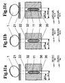
- the enclosing figure 32, as in rectangular shape in 10a and 10b can also be based on the definition of a left start limit 35 (StartX) and a right end limit 36 (EndX), as in Fig. 11a to 11c be limited indicated if the calculation of the enclosing figure 32 for reasons of almost complete utilization of the receiving surface 21 laterally to the rolling direction of the finger 1 not worthwhile.
- the found values are entered into the register of the sensor 22 of the image acquisition unit 2, which then only records and reproduces this range when the next image 31 is read out.
- the RSR routine 63 compares the positions of FIG. 32 with those of the previous image images 32.
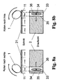
- Fig. 8a and Fig. 8b is each stylized a rolling process to the right and to the left.
- the receiving surface 21 is sensibly divided into three thirds in order to position the finger 1 correctly so that the fingerprint 11 is completely unrolled onto the receiving surface 21.
- the finger 1 is preferably placed in the second third and rolled into the first or third third. In this case, a rolling movement is already performed, whereby the center of gravity 34 and the boundaries 35 and 36 (StartX and EndX) of the rectangle 33 change.
- the finger 1 is placed in the middle of the support surface 21 on the second third and rolled to the left to a starting point for the complete rolling process.
- the center of gravity, the (left) start boundary 35 and (right) end boundary 36 of the rectangle 33 are also moved to the left.
- the rolling process can be started by the finger 1 is rolled to the right.
- the changed direction of movement of the (right-hand) end boundary 36 is preferably detected and the occurrence of this event is communicated to all system components which require this information.
- the detection of the starting point can also be determined by shifting the center of gravity or as a combination of the reversal of movement from the end boundary 36 and the center of gravity 34.
- the indicators serve to change both the direction of displacement of the center of gravity 34 and the direction of displacement of the end boundary 36 (EndX Line) of the rectangle 33.
- This variant is more robust than the first two.
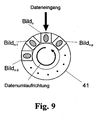
- a kind of ring buffer memory 41 is required to process the read-out images 31 (see FIG Fig. 9 ), in which all images 31, which are stored from the actual starting point of the rolling process up to the image 31, from which the starting point is determined, are buffered.
- at least a number p of images 31 must fit into the ring buffer memory 41 as needed to determine the beginning of the unrolling process. If the starting point is established, first all the images 31 are read out of the ring buffer memory 41 and forwarded for processing. In the event that you want to unroll to the left, everything behaves the same, except that not the right, but the start boundary 35 (left border of the rectangle 33) is used for viewing.
- Arithmetic unit 4 eg a PC
- the arithmetic unit 4 is also informed of how many images 31 were used for the determination of the unwinding process, so that it is buffered from a buffer memory in which the images 31 already used for the adjustment of the active pixel area 23 of the image acquisition unit 2 are stored of the overall picture 3 used.
- a ring buffer memory 41 according to Fig. 9 in which the images 31 required for the RSR routine 63 are buffered.
- the number of memory locations in the buffer 41 must be one greater than the number of frames 31 used to determine the roll-off. If a starting point of a rolling process has been detected, loop 2 in Fig. 1 finished and passed into the loop 3. This starts again with a support test (see PR routine 61) to end the recording of the rolling process in the unexpected start of the finger 1. If a valid fingerprint 11 is still present, it will switch to roll-over tracking.
- the RT routine 64 is used to track the finger 1 during the defined unwinding. It not only determines the center of gravity 34 and the boundaries 35 and 36 of the fingerprint 11, such as the motion track 62, but also determines the speed of the roll-off operation by adjusting the speed of the center of gravity 34 and / or the speed of the respective boundaries 35 and 36 of the rectangle 33 separately be calculated. In addition, the acceleration of the finger center of gravity 34 and / or the respective rectangle boundaries 35 and 36 is determined to detect short-term changes in the unwinding speed.
- the tolerance between the enclosing figure 32 of the fingerprint 11 and the boundaries 35 and 36 of the enlarged rectangle 33 can be made smaller, in contrast to the MT algorithm 62 ,
- the tolerance range must be chosen to be relatively large and thus image readout time is wasted. This is not problematic in the MT routine 62 since the captured fingerprint 11 is used only for visualization. In a rolling process, however, it is necessary to read out as many images 31 per second as possible, since any increase in the readout speed will improve the proper composition of the overall image 3. Therefore, with a priori knowledge about the started rolling process, the readout time can be significantly reduced.
- the Abrollstarterkennung 63 in which direction is rolled, ie the tolerance range must have only in one direction the maximum value.
- the speed and possibly occurring accelerations can be calculated, thereby making a more accurate prediction of the boundaries of the figure 32 enclosing the fingerprint 11 and thus of the required rectangle 33.
- the procedure for determining the speed is in Fig. 11a to 11c shown.
- the speed of the center of gravity in the x-direction eg centroid of the imprint, center of gravity calculated as the difference of the boundaries 35 and 36 of the enclosing figure 32 in the x-direction
- the velocities of the two boundaries in X direction For the velocities in y-directions, this applies analogously if rolling in the y-direction is implemented.
- the index n describes an arbitrary instant of the taking of an image 31 in the value range of 0 ⁇ n ⁇ N-1, with N as the total number of all captured images 31.
- n-1 is the time of the predecessor and n + 1 of the successor.
- ⁇ t represents the cycle time, ie the time it takes to read out the active pixel region 23 and thus a limited image 31.
- f PixelClock is the pixel clock between 12 to 27 MHz of the sensor 22. With this pixel clock, the individual pixels are read out.
- N Rows and N Column are the number of rows and columns needed in the active pixel area 23 of the sensor 22.
- R opcycle is a fixed integer value of 140. This is the time required to complete all intermediate steps before and after reading one row of the sensor 22 is needed.
- R Itime has a fixed integer value of 34, otherwise R Itime is zero. This results, for example, in the case of a pixel frequency of 25 MHz and a complete readout of the sensor 22 with 1280 ⁇ 1024 pixels, a frame rate of 16.8 images per second.
- the width of the image 31 is reduced to half (640 x 1024 pixels), for example, and a frame rate of 30 B / s (frames per second) is achieved.
- Another physical quantity for calculating the prediction of the next boundary 35 or 36 of the rectangle 33 is the acceleration. It takes into account any speed change in the calculation.
- the acceleration is determined from the two preceding speeds, whereby the first prediction is to be performed without an acceleration calculation.
- a routine is presented below which realizes a more accurate prediction of the boundaries 35 and 36 of the rectangle 33.
- the basic requirement is that after the already presented RT routine 64, the exact limits 35 and 36 of the Fingerprint 11 and the surrounding him figure 32 were determined and that are made as initial conditions two assumptions. Since at least two images 31 are needed to determine the velocity, an assumption must be made, since otherwise no prediction can be made for determining the position of the boundaries of the second image 31. Therefore, when a rolling operation by the RSR routine 63 has been judged to be started, it is assumed that the position of the start boundary 35 for the first image 31 is equal to the position of the start boundary 35 for the second image 31.
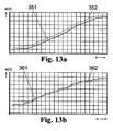
- Fig. 13 the results of the method are shown, where s (n) is the movement of the position of the start limit 35 and e (n) is the movement of the position of the end limit 36.
- the representations of the Fig. 13a and 13b represent a rolling movement from an origin at pixel 0 to the maximum value of the respective image capturing unit 2.
- Fig. 13a is the movement of the position of the start boundary 35, where the solid line represents the predicted position 351 of the start boundary 35 of the rectangle 33 and the broken line represents the actual reached position 352 of the imaged fingerprint 11.
- the position 352 actually reached must not be below the solid line of the calculated position 351, since otherwise the fingerprint 11 will be judged.
- x '(n + 1) is either the position to be calculated of the start limit s' (n + 1) or the end limit e' (n + 1).
- the apostrophe means that it is a predictable quantity that is not used to calculate the value after the second.
- the quantity a x (n) represents the acceleration and v x (n) the speed of the starting value (a s , v s ) or of the final value (a E , v E ) at the current time.
- the current position is represented by x (n).
- Tol1 is the tolerance of the start value when scrolling from left to right. It may be smaller than the tolerance Tol2 of the final value, since the position 352 of the start limit 35 at time n is definitely smaller than the position 352 of the start limit 35 at time n + 1. Thus, as the predicted position 351 of the start limit 35 at time n + 1, theoretically, the actual position 352 of the start limit 35 may be taken at time n and Tol1 may take the value 0. However, since the detection of the roll-off occurs within the roll-off sequence and the direction change is a feature for the roll-off end, a certain size must be used for the tolerance Tol1.
- Tol1 may again be smaller than Tol2, since the rolling process is carried out from right to left and the final boundary 36 at time n is definitely greater than the position 362 of the end boundary 36 at time n + 1.
- the position of the subsequent rectangle 33 results from these values, and the fixed rectangle size must be placed around the calculated enclosing figure 32 such that the distances of the boundaries of the rectangle 33 from the minimum start value and the maximum end value of the enclosing figure 32 are equal on all sides ,
- the resulting position of the solid rectangle 33 is programmed in the image acquisition unit 2 as an active pixel region 23 for the subsequent image 31.
- the positioning of the rectangle 33 which is always the same size, can also - as described above - be carried out with the aid of a center of gravity algorithm which, for example, searches for the centroid of the fingerprint 11 and places the solid rectangle 33 around it. This has the consequence that a circumcision of the fingerprint 11 can not be excluded.
- the excising of an enlarged rectangle 33 containing the fingerprint 11 can also take place outside the image acquisition unit 2, if the data rate when reading the complete sensor 22 is sufficient, but the limiting element for the required data rate is the transmission channel.
- the method according to the invention can be applied in the same way, except that the frame as picture 31 is present as the basis for calculation and not already a selected active pixel area 23. It is then no longer necessary to make a prediction where the next start or stop is Final limit 35 or 36 is because you have the image 31 as a frame of the image pickup unit 2 available, so you can do without the calculation of speeds and accelerations. That is, by a high frame rate image pickup unit 2, the frame in the processing unit 5 (in accordance with FIG Fig.
- the start limit 35 is maintained as an input value without recalculation of speed or acceleration, but increases the tolerance.
- RT routine 64 is as in FIG Fig. 1 seen, surrounded by the support detection 61 and a Abroll gleicherkennung 65 (RER routine). PR routine 61 and RER routine 65 check whether the finger 1 has been lifted during the rolling process or the finger 1 has been moved over a series of images 31 in the opposite direction to the detected rolling direction. If the finger 1 was lifted during the unwinding, this is detected by the PR routine 61 and interpreted as a rolling shut-off. The other way of terminating the RT routine 64 is effected by a roll-off detection 65, which will be explained below.
- an RER routine 65 it is determined whether or not a coasting operation has been completed. In this case, the positions determined by the RT routine 64 of the start and end limits 35 and 36 of the rectangle 33 are used. At a Rolling operation, the user should, if he wants to end the rolling process, be prompted to roll the finger 1 against the original rolling direction. As a result, the limits 35 and 36 determined by the RT algorithm (for example via more than three images 31) change counter to the original scrolling direction. This can then be interpreted unambiguously as rolling closure. In order to make the RER routine 65 robust, it is expedient to use 5 images to make sure that the unwinding process has ended.
- the roll-off is evaluated as the lifting of the finger 1, which is detected by the PR routine 61 described above. If the roll-off has been detected, the registers in which the adapted rectangle 33 was stored as the active pixel region 23 of the sensor 22 are deleted in the image acquisition unit 2, so that again the entire sensor surface is switched active.
- Fig. 5 a structure is shown, which subsequently to the image pickup unit 2, a logic unit 51, a processor 54, a program memory 52, a data memory 53 and an interface 55, wherein the logic unit 51 and the processor 54 may be combined as a data processing or processing unit. Also, the program and data memory 67 and 68 can be to a memory be summarized. As processor 54, the CPU of the external computing unit 4 could also be used.
- the image pickup unit 2 whose sensor is based on CMOS or CCD technology preferably includes a drive circuit and an analog-to-digital converter.
- CMOS or CCD technology preferably includes a drive circuit and an analog-to-digital converter.
- fingerprint 11 as a two-dimensional digital image 31 at the output of the image acquisition unit 2. This is written to the data memory 53 via the logic unit 51.
- the processing unit 5 the above-described algorithms and processing routines are executed.
- the logic unit 51 can be implemented by a FPGA (Field Programmable Gate Array), PLD (Programmable Logic Device), ASIC (Application Specific Integrated Circuit).
- a microcontroller MCU
- MPU microprocessor
- DSP digital signal processor
- the processor 54 can also be completely dispensed with if the logic unit 51 is able to perform all functions, including communication with the interface 55 itself. Conversely, the logic unit 51 can be dispensed with if the processor 54 is able to realize all the tasks of the logic unit 51.
- the image data bus 57 would then have to be led by the processor 54 to the interface 55 and a direct coupling of the processor 54 to the data memory 53 would exist.
- the interface 55 represents the interface to the outside and can be arbitrary (eg USB2.0, IEEE1394, Ethernet).
- the processing routines 61 to 65 can also be partially or completely also outside, for example with the in Fig. 5 represented external computing unit 4, executed and the setting of the active pixel area 23 in the register of the image pickup unit 2 are controlled via the interface 55 (and possibly the logic unit 51).
Landscapes
- Engineering & Computer Science (AREA)
- Human Computer Interaction (AREA)
- Physics & Mathematics (AREA)
- General Physics & Mathematics (AREA)
- Multimedia (AREA)
- Theoretical Computer Science (AREA)
- Measurement Of The Respiration, Hearing Ability, Form, And Blood Characteristics Of Living Organisms (AREA)
- Image Input (AREA)
- Collating Specific Patterns (AREA)
- Length Measuring Devices By Optical Means (AREA)
- Studio Devices (AREA)
Abstract
Description
Die Erfindung betrifft ein Verfahren und eine Anordnung zur elektronischen Aufnahme eines bewegten Objekts, insbesondere zur Aufnahme eines auf einer Auflagefläche abgerollten Fingers. Die Erfindung findet vornehmlich Anwendung für die Erstellung elektronischer Fingerabdrücke, kann aber ebenso vorteilhaft bei der Objektverfolgung zur intelligenten Steuerung eines in Position und/oder Größe variablen Abtastfensters eingesetzt werden.The invention relates to a method and an arrangement for the electronic recording of a moving object, in particular for receiving a finger which has been unrolled on a support surface. The invention finds primarily application for the production of electronic fingerprints, but can also be used to advantage in object tracking for the intelligent control of a variable in position and / or size sampling window.
Der Hintergrund für die Verwendung von Fingerabdrücken in der Kriminalistik liegt an der Einmaligkeit der Hautleistenbilder, die nicht vererbbar sind und die ab dem vierten embryonalen Monat bis zur Auflösung nach dem Tode unveränderlich sind. Als Bildvorlage kann der Finger selbst, ein mittels Tinte auf Papier aufgebrachter Fingerabdruck oder ein Spurenphotogramm dienen. Die letzteren beiden Techniken wurden und werden vornehmlich durch die Polizei angewendet. Mit Hilfe von Mustererkennungstechniken, die in der Lage sind, die charakteristischen Merkmale eines Fingerabdrucks zu extrahieren, ist es möglich, die Identifikation und Verifikation von Fingerabdrücken zu automatisieren.The background for the use of fingerprints in forensics is the uniqueness of the dermal scar images, which are not inheritable and which are immutable from the fourth embryonic month to dissolution after death. The image template can be the finger itself, a fingerprint applied to paper by ink or a trace photogram. The latter two techniques were and are mainly used by the police. With the help of pattern recognition techniques capable of extracting the characteristics of a fingerprint, it is possible to automate the identification and verification of fingerprints.
In den letzten Jahren wurden die oben erwähnten Techniken zunehmend in elektronische Systeme integriert, die es gestatten, den Finger direkt aufzunehmen. Damit verkürzt sich die Aufnahme- und Auswertezeit, wodurch sich gleichzeitig die Qualität der Bilder verbessern lässt. Wurde ein Finger nicht richtig erfasst, ist es dadurch möglich, den Vorgang der Aufnahme dieses einen Fingers sofort zu wiederholen.
Die elektronische Bildaufnahme von Fingerabdrücken erfolgt meist mit Matrix- oder Zeilensensoren auf Basis von CCD- oder CMOS-Technik. Dabei wird der Fingerabdruck als Bildvorlage durch spezielle Optiken und Sensoren in ein elektronisches Bild umgewandelt und anschließend digitalisiert, wodurch ein Rasterbild mit einer festen Orts- und Grauwertauflösung entsteht.
Zur Aufnahme von elektronischen Fingerabdrücken können aber auch kapazitive, thermische, ultraschallbasierte oder drucksensitive Sensoren verwendet werden.In recent years, the above-mentioned techniques have increasingly been integrated into electronic systems that allow the finger to be picked up directly. This shortens the recording and evaluation time, which at the same time improves the quality of the images. If a finger has not been detected correctly, it is possible to immediately repeat the process of recording that one finger.
The electronic image capture of fingerprints is usually done with matrix or line sensors based on CCD or CMOS technology. Here, the fingerprint is converted as an image template by special optics and sensors in an electronic image and then digitized, creating a raster image with a fixed spatial and gray scale resolution.
However, capacitive, thermal, ultrasound-based or pressure-sensitive sensors can also be used to record electronic fingerprints.
Von der Polizei werden neben der Aufnahme von bloßen Abdrücken der Finger vor allem auch Abbilder abgerollter Finger erstellt.
Dabei ist die Prozedur zur Herstellung abgerollter Fingerabdrücke mit Tinte und Papier hinreichend einfach, indem auf den Finger Tinte aufgetragen und der Finger danach auf Papier abgerollt wird. Rotation und VerformungenNerschmierungen an den Enden des Fingers werden dabei akzeptiert und sind zulässig.
Bei elektronischen Systemen ist eine solche Prozedur etwas aufwendiger. Hier wird, je nachdem wie der Finger elektronisch erfasst wird (mit Zeile oder Matrix), ein Gesamtbild aus vielen Einzelbildern zusammengesetzt. Dabei besteht das Problem, das gegenüber dem Abrollen mit Tinte auf Papier keine komplette Aufnahme, sondern eine Vielzahl zeitdiskreter Abtastungen entsteht, die einen Informationsverlust in sich bergen. Die Ursachen für den Informationsverlust sind neben der Verformung des Fingers und den darausfolgenden Veränderungen zu zwei unterschiedlichen Zeitpunkten besonders in einer zu geringen zeitlichen Abtastung des Fingers durch die Bildaufnahmeeinheit begründet. D.h., um sicherzustellen, dass ein Finger korrekt aufgenommen wird, muss die Bildaufnahmeeinheit - je nach verwendetem Verfahren des Zusammensetzens - eine Mindestbildrate aufweisen, damit störende Vorgänge, wie z.B. Verdrehen oder Verrutschen beim Abrollvorgang des Fingers, detektiert werden können.In addition to the recording of mere fingerprints of the fingers, the police also create images of unrolled fingers.
The procedure for producing unrolled fingerprints with ink and paper is simple enough, as ink is applied to the finger and the finger is then unrolled onto paper. Rotation and deformationsNegreases at the ends of the finger are accepted and are permissible.
In electronic systems, such a procedure is somewhat more complicated. Here, depending on how the finger is detected electronically (with line or matrix), an overall picture is composed of many individual pictures. There is the problem that compared to the unrolling with ink on paper, not a complete shot, but a variety of discrete-time scans arises, which entail a loss of information in itself. The causes for the loss of information are due not only to the deformation of the finger and the resulting changes at two different points in time, especially in too little temporal scanning of the finger by the image acquisition unit. That is, to ensure that a finger is picked up correctly, the image acquisition unit must have a minimum frame rate, depending on the method of assembly used, so that disturbing processes, such as twisting or slipping during the rolling process of the finger, can be detected.
Methoden, wie man von den unvermeidlichen Einzelbildern zu einem fehlerminimierten Gesamtbild kommt, sind mehrfach beschrieben worden, wobei zur Erstellung des Abbildes eines abgerollten Fingers stets von einer sukzessive aufgenommenen Folge elektronischer Einzelbilder ausgegangen wird. Das Gesamtbild wird aus diesen Einzelbildern mittels verschiedenster Verfahren zusammengesetzt. Hierbei werden - die Einzelbilder in Streifen zerlegt.
In den Druckschriften
In the pamphlets
Bei allen oben aufgeführten Druckschriften haben die von der Bildaufnahmeeinheit kommenden Einzelbilder eine feste Größe und basieren auf einem festgelegten Zeitregime (vorgegeben durch einen Taktgenerator oder einen Ereignistrigger). Dadurch können die Abrollgeschwindigkeit (und gegebenenfalls deren Änderung) sowie die Größe der Fingerkontaktfläche (und deren reale Änderung im Abrollvorgang) im Ausleseregime der Bildaufnahmeeinheit nicht berücksichtigt werden.
Um ein korrektes Berechnen des Ergebnisbildes zu ermöglichen, müssen zwei benachbarte Fingerabdruckstreifen eine für das jeweilige Verfahren hinreichend große Schnittmenge haben. Das kann nur erreicht werden, wenn beim Abrollen des Fingers eine schnelle zeitliche Abtastung erfolgt. Dies wird derzeit durch Sensoren mit einer hohen Bildauslesegeschwindigkeit (Bildrate) von mehr als 25 Bilder/Sekunde (B/s) realisiert. Bei Erhöhung der Ortsauflösung (z.B. von 500 dpi auf 1000 dpi) stößt man damit allerdings an die technischen Grenzen. Entweder verringert sich die Bildrate (z.B. beim Übergang von 500 dpi zu 1000 dpi Reduzierung der Bildrate auf 1/4) oder der Preis des Sensors mit seiner Elektronik wird unakzeptabel hoch.In all of the references listed above, the frames coming from the imaging unit have a fixed size and are based on a fixed time regime (dictated by a clock generator or an event trigger). As a result, the unwinding speed (and possibly its change) as well as the size of the finger contact surface (and its real change in the unrolling process) can not be taken into account in the readout regime of the image pickup unit.
In order to allow a correct calculation of the result image, two neighboring fingerprint strips must have a sufficiently large intersection for the respective method. This can only be achieved if a fast time sampling occurs when rolling the finger. This is currently being realized by sensors with a high image read rate (frame rate) of more than 25 frames / second (B / s). Increasing the spatial resolution (eg from 500 dpi to 1000 dpi), however, pushes you to the technical limits. Either the frame rate (for example at the transition from 500 dpi to 1000 dpi reducing the frame rate to 1/4) or the price of the sensor with its electronics is reduced unacceptably high.
Der Erfindung liegt deshalb die Aufgabe zugrunde, eine neue Möglichkeit zur elektronischen Aufnahme von abgerollten Fingerabdrücken zu finden, die hochaufgelöste Einzelbilder und eine enge Bildfolge zur lückenlosen Zusammensetzung der Einzelbilder zu einem Gesamtbild gestattet, ohne dass auf teure Bildsensoren mit hoher Bildrate (Auslesegeschwindigkeit) zurückgegriffen werden muss.The invention is therefore based on the object to find a new way to electronically record unrolled fingerprints, the high-resolution frames and a tight sequence of images for seamless composition of the individual images to an overall picture without resorting to expensive image sensors with high frame rate (read speed) got to.
Erfindungsgemäß wird die Aufgabe bei einem Verfahren zur elektronischen Aufnahme eines bewegten Objekts, insbesondere zur Aufnahme eines an einer Aufnahmefläche abgerollten Fingers, wobei das Objekt mit seinen Strukturen während der Bewegung mittels einer ortsauflösenden Bildaufnahmeeinheit in einer Folge von Einzelbildern erfasst und als zweidimensionales elektronisches Bild verarbeitet wird, dadurch gelöst, dass aus Lage und Größe des Objekts in mindestens einem der aus der Bildaufnahmeeinheit ausgelesenen einzelnen Bilder eine das Objekt umschließende Figur ermittelt wird, dass aus der umschließenden Figur ein durch Toleranzzugaben vergrößertes Rechteck, das parallel zu Zeilen- und Spaltenrichtung des Sensors ausgerichtet ist, bestimmt wird, und dass das vergrößerte Rechteck zur Vorhersage und Einstellung der Größe und Lage eines aktiven Pixelbereichs der Bildaufnahmeeinheit für mindestens ein nachfolgend auszulesendes Bild verwendet wird, so dass der ausgelesene aktive Pixelbereich der Bildaufnahmeeinheit infolge seiner Anpassung stets klein gehalten und eine höhere Bildrate bei der Sensorauslesung oder Datenübertragung realisiert wird.According to the invention, the object is achieved in a method for the electronic recording of a moving object, in particular for recording a finger unrolled on a recording surface, wherein the object is detected with its structures during movement by means of a spatially resolving image recording unit in a sequence of individual images and processed as a two-dimensional electronic image , is achieved by determining from the position and size of the object in at least one of the individual images read out of the image recording unit a figure enclosing the object, that from the enclosing figure rectangle magnified by tolerance additions aligned parallel to the row and column direction of the sensor, and that the enlarged rectangle is used to predict and adjust the size and location of an active pixel area of the image acquisition unit for at least one subsequently read image, such that the read active pixel range of the image pickup unit due to its adaptation always kept small and a higher frame rate in the sensor reading or data transmission is realized.
Vorteilhaft wird die umschließende Figur des Objektabbildes des aktuell abgetasteten Bildes durch je ein in Spalten- und in Zeilenrichtung gebildetes Gradientenbild ermittelt, wobei zur Erzeugung des Gradientenbildes für jedes Pixel eine Differenz benachbarter Grauwerte in Zeilen- oder in Spaltenrichtung gebildet wird.
Dabei ist es zweckmäßig, zur Erstellung jedes Pixels des Gradientenbildes die Differenz benachbarter Grauwerte aus den Grauwerten des Vorgänger- und des Nachfolgerpixels des aktuell untersuchten Pixels der Zeile oder Spalte zu bilden.
Um Ränder des Fingerabdrucks besonders zuverlässig extrahieren zu können, werden die Pixel jedes Gradientenbildes vorzugsweise aus der Differenz der Grauwerte des Vorvorgänger- und des Nachnachfolgerpixels des aktuell untersuchten Pixels der Zeilen bzw. Spalten gebildet.
Für ein aktuelles Bild werden vorteilhaft aus mindestens einem Gradientenbild der Zeilen oder Spalten, das in Richtung der Objektbewegung ausgerichtet ist, Start- und Endwerte der umschließenden Figur des Objektabbildes ermittelt, wobei eine erste und eine letzte signifikante Differenz benachbarter Grauwerte je Zeile bzw. Spalte zur Berechnung der Start- und Endwerte der das Objekt umschließenden Figur bestimmt wird.
Die signifikanten Differenzen werden zweckmäßig durch Überschreiten von Schwellwerten ermittelt.
Es erweist sich als vorteilhaft, in mindestens einer Dimension, die der Hauptbewegungsrichtung des Objekts entspricht, von den aus dem Gradientenbild ermittelten Start- und Endwerten einen Mittelwert oder einen Medianwert zu berechnen, wobei die Mittel- bzw. Medianwerte dann lineare Grenzen einer das Objektabbild rechteckig umschließenden Figur bilden.Advantageously, the enclosing figure of the object image of the currently scanned image is determined by a respective gradient image formed in the column and in the row direction, a difference of adjacent gray values in the row or in the column direction being formed for the generation of the gradient image for each pixel.
In this case, it is expedient to form the difference of adjacent gray values from the gray values of the predecessor and successor pixels of the currently examined pixel of the row or column in order to produce each pixel of the gradient image.
In order to be able to extract edges of the fingerprint with particular reliability, the pixels of each gradient image are preferably formed from the difference between the gray values of the preceding and succeeding pixel of the currently examined pixel of the rows or columns.
For a current image, start and end values of the enclosing figure of the object image are advantageously determined from at least one gradient image of the rows or columns aligned in the direction of the object movement, a first and a last significant difference of adjacent gray values per row or column Calculation of the start and end values of the figure enclosing the object is determined.
The significant differences are expediently determined by exceeding threshold values.
It proves advantageous to calculate an average value or a median value of the start and end values determined from the gradient image in at least one dimension which corresponds to the main movement direction of the object, the mean or median values then being linear boundaries of the object image being rectangular form enclosing figure.
In einer vorzuziehenden Ausführung werden die Start- und Endwerte mindestens aus dem Gradientenbild, das der Hauptbewegungsrichtung des Objekts entspricht, in ein Ortshistogramm eingetragen, wobei die Orte, an denen die integrale Häufigkeitsverteilung einen signifikanten Schwellwert erreicht, die Grenzen einer das Objektabbild rechteckig umschließenden Figur bilden. Dieser Schwellwert kann sinnvoll 5% der integralen Häufigkeitsverteilung sein. Es ist aber auch möglich, den Maximalwert der Häufigkeitsverteilung zu wählen
Zur Einsparung von Rechen- und Speicherkapazität erweist es sich von Vorteil, für die Ermittlung der Grenzen der rechteckig umschließenden Figur nur die Start- und Endwerte ausgewählter Zeilen oder Spalten des Gradientenbildes zu verwenden.In a preferred embodiment, the start and end values are entered into a location histogram at least from the gradient image that corresponds to the main movement direction of the object, the locations at which the integral frequency distribution reaches a significant threshold form the boundaries of a figure enclosing the object image in a rectangular manner , This threshold value can make
To save on computational and storage capacity, it is advantageous to use only the start and end values of selected rows or columns of the gradient image for determining the boundaries of the rectangular enclosing figure.
Um eine Beschneidung des Objektabbildes zu vermeiden, wird eine Toleranzzugabe zur Erzeugung des vergrößerten Rechtecks zweckmäßig in Abhängigkeit von einem detektierten Bewegungsablauf des Objekts unterschiedlich festgelegt, wobei aus mindestens zwei vorhergehend ausgelesenen Bildern nach der Bestimmung der Grenzen der jeweils umschließenden Figur unterschiedliche Bewertungsalgorithmen auf Basis der zeitlichen Veränderung der Grenzen der umschließenden Figur in den aufeinander folgenden Bildern angewendet werden.In order to avoid circumcision of the object image, a tolerance addition for generating the enlarged rectangle is determined differently depending on a detected movement sequence of the object, wherein from the at least two previously read images after determining the boundaries of the respective enclosing figure different evaluation algorithms based on the temporal Changing the boundaries of the enclosing figure can be applied in the successive pictures.
Vorzugsweise wird als Objekt ein auf einer Aufnahmefläche abrollender Finger erfasst, wobei als Objektabbild in jedem ausgelesenen Bild ein Fingerabdruck als momentane Auflagefläche des Fingers aufgenommen wird.
Dabei werden zur Einstellung der Grenzen der einzelnen Bilder vorteilhaft folgende Schritte auf jedes der ausgelesenen Bilder angewendet:
- eine Auflageerkennungs-Routine, die bei Ermittlung einer nicht ausreichenden Anzahl von durch einen Fingerabdruck hervorgerufenen Differenzwerte die Berechnung der Toleranzzugabe und nachfolgende Vorhersagen und Einstellungen des aktiven Pixelbereichs der Bildaufnahmeeinheit unterbindet;
- eine Bewegungsverfolgungs-Routine, die bei nicht deutlich gerichteter Bewegung der umschließenden Figur eines Fingerabdrucks eine allseitig gleichmäßige Toleranzzugabe um die Grenzen der umschließenden Figur herum bestimmt, die so groß gewählt wird, dass bei beliebiger Bewegung des Objekts in objekttypischem Maße das vergrößerte Rechteck das Objekt innerhalb der Zeit der Auslesung wenigstens eines nächsten Bildes nicht beschneidet; und
- eine Abrollverfolgungs-Routine überführt wird, wenn sich in einer definierten Anzahl von aufeinanderfolgenden Bildern die Grenzen der umschließenden Figur deutlich in eine ausgezeichnete Richtung verschoben haben, wobei für die in Bewegungsrichtung des Objekts bewegte Grenze der umschließenden Figur aus einer errechneten Geschwindigkeit der bewegten Grenze eine solche Toleranzzugabe ermittelt wird, dass das vergrößerte Rechteck das momentane Objektabbild (Fingerabdruck) innerhalb der Zeit von wenigstens einem nachfolgend ausgelesenen Bild nicht beschneidet.
The following steps are advantageously applied to each of the read-out images for setting the boundaries of the individual images:
- a pad detection routine that, upon detection of an insufficient number of fingerprint differential values, inhibits calculation of the tolerance allowance and subsequent predictions and adjustments of the active pixel area of the imaging unit;
- a motion-tracking routine, which, when the movement of the surrounding figure of a fingerprint is not clearly directed, determines an all-round uniform tolerance addition around the boundaries of the surrounding figure, which is chosen to be so large that any movement of the object in object-typical The enlarged rectangle does not truncate the object within the time of reading at least one next image; and
- a tracing-following routine is carried out when, in a defined number of successive pictures, the boundaries of the enclosing figure have clearly shifted in an excellent direction, and for the limit of the enclosing figure moving in the direction of movement of the object, from a calculated velocity of the moving boundary Tolerance addition is determined that the enlarged rectangle does not crop the current object image (fingerprint) within the time of at least one subsequently read image.
Da die Abrollverfolgungsroutine das Kernstück der Bildaufnahme eines abgerollten Fingers darstellt, um eine vollständige und zeitlich hochaufgelöste Serie von einzelnen Bildern für die Zusammensetzung des kompletten Abdrucks eines abgerollten Fingers zur Verfügung zu stellen, wird die Abrollverfolgung zweckmäßig durch eine Abrollstarterkennung, die bei Vorliegen einer bestimmten festgelegten Zahl von in gleicher Richtung fortschreitenden Verschiebungen der Grenzen der umschließenden Figur die Bewegungsverfolgung in die Abrollverfolgung umschaltet, eingeleitet und durch eine Abrollschlusserkennung, die bei einer Richtungsumkehr der Bewegung der Grenzen der umschließenden Figur die Abrollverfolgung abbricht, beendet.Since the roll-over trace routine is at the heart of the image capture of a rolled-up finger to provide a complete, high-resolution series of individual images for the composition of the complete footprint of a rolled-up finger, roll-off tracking is conveniently accomplished by a roll-off detection that is in place Number of progressions in the same direction shifts the boundaries of the enclosing figure, the motion tracking switches to the roll tracking, initiated and terminated by a Abrollschlusserkennung, which terminates the Abrollverfolgung at a reversal of direction of movement of the boundaries of the surrounding figure.
Beim Abrollen eines Fingers entlang einer Aufnahmefläche wird innerhalb der Abrollstarterkennung vorteilhaft eine Zwischenspeicherung aller zur Starterkennung verwendeten Bilder vorgenommen, um die bereits ausgelesenen Bilder für die spätere vollständige Zusammensetzung des abgerollten Fingers zur Verfügung zu halten.When rolling a finger along a recording surface, an intermediate storage of all images used for the start detection is advantageously carried out within the Abrollstarterkennung to keep the already read images for the subsequent complete composition of the unrolled finger available.
Des Weiteren wird die Aufgabe der Erfindung bei einer Anordnung zur elektronischen Aufnahme eines bewegten Objekts, insbesondere zur Aufnahme eines an einer Aufnahmefläche abgerollten Fingers, mit einer Bildaufnahmeeinheit zur Aufnahme einer Folge von zweidimensionalen Einzelbildern eines bewegten Objekts, wobei zur Zusammensetzung eines Gesamtbildes des bewegten Objekts die Einzelbilder örtliche Überlappungen aufweisen, erfindungsgemäß dadurch gelöst, dass der Bildaufnahmeeinheit eine Logikeinheit zur laufenden Berechnung eines eingeschränkten Pixelbereichs, der das Objektabbild eng einschließt, auf Basis mindestens eines von der Bildaufnahmeeinheit zuvor ausgelesenen Bildes, nachgeordnet ist, dass der Logikeinheit ein Programmspeicher, ein Datenspeicher, ein Prozessor und ein Interface zugeordnet sind, wobei der Prozessor zur Steuerung der Datenflüsse vorgesehen ist, und dass das Interface zum Datentransfer der Bilder, die von der Logikeinheit bezüglich Größe und Lage Ihres Pixelbereichs definiert gesteuert sind, an eine externe Rechnereinheit vorhanden ist, wobei die Rechnereinheit die Bildverarbeitung zum Zusammensetzen der zeitlich aufeinanderfolgend aufgenommenen Bilder zu einem Gesamtbild enthält.Furthermore, the object of the invention in an arrangement for electronically recording a moving object, in particular for recording a finger unrolled on a recording surface, with an image recording unit for recording a sequence of two-dimensional individual images of a moving object, wherein the composition of an overall image of the moving object Individual images have local overlaps, according to the invention solved in that the image pickup unit a logic unit for the current calculation of a a limited pixel area, which encloses the object image closely, on the basis of at least one image previously read by the image acquisition unit, in that the logic unit is assigned a program memory, a data memory, a processor and an interface, the processor being provided for controlling the data flows, and in that the interface for data transfer of the images, which are controlled in a defined manner by the logic unit with respect to size and position of their pixel area, is present on an external computer unit, wherein the computer unit contains the image processing for assembling the temporally successively recorded images into an overall image.
Die Bildaufnahmeeinheit weist vorzugsweise einen optoelektronischen Sensor auf, kann aber auch mit einem kapazitiven, induktiven, thermischen, Ultraschall- oder andersartigen Kontaktsensor ausgestattet sein.
Als optoelektronische Bildaufnehmer werden zweckmäßig CCD-Arrays oder CMOS-Arrays (jeweils als Matrix- oder Zeilenanordnung) verwendet.The image acquisition unit preferably has an optoelectronic sensor, but may also be equipped with a capacitive, inductive, thermal, ultrasonic or other type of contact sensor.
Suitable optoelectronic image sensors are CCD arrays or CMOS arrays (each in the form of a matrix or line array).
Vorteilhaft kann die Bildaufnahmeeinheit auch einen Sensor mit niedriger Bildrate (< 25 B/s) enthalten, bei dem die niedrige Bildrate nur auf die Auslesung aller Pixel des Sensors bezogen ist, die Auslesung von Bildern aus einem beliebig programmierbaren aktiven Pixelbereich jedoch mit wesentlich größerer Bildrate realisierbar ist.
In einer erweiterten Variante der Erfindung weist die Bildaufnahmeeinheit vorzugsweise einen großflächigen Sensor auf, bei dem durch eine einzige Sensorauslesung ein kompletter Fuß- oder Handabdruck mit hoher Auflösung, aber niedriger Bildrate realisierbar ist, bei dem zur Aufnahme einzelner abgerollter Finger ein definierter Teilbereich der Aufnahmefläche festgelegt ist, wobei der Sensor in einem entsprechend beschränkten aktiven Pixelbereich, der dem definierten Teilbereich der Aufnahmefläche für den abzurollenden Finger zugeordnet ist, zur Auslesung von pixelreduzierten Bildern ansteuerbar ist, so dass die Bildrate zur Aufnahme abgerollter Fingerabdrücke gegenüber der von Fuß- oder Handabdrücken erheblich erhöht wird.Advantageously, the image acquisition unit can also contain a sensor with a low frame rate (<25 B / s), in which the low frame rate is based only on the reading of all pixels of the sensor, but the reading of images from an arbitrarily programmable active pixel area with a much larger frame rate is feasible.
In an expanded variant of the invention, the image acquisition unit preferably has a large-area sensor in which a complete footprint or handprint with high resolution but low frame rate can be realized by a single sensor reading, in which a defined partial area of the receiving surface is defined for receiving individual unrolled fingers is, wherein the sensor in a correspondingly limited active pixel area, which is assigned to the defined portion of the receiving area for the unrolling finger, for reading pixelreduced images is controllable, so that the frame rate for recording unrolled fingerprints compared to foot or hand prints significantly increased becomes.
In einer modifizierten Variante der Erfindung kann die Bildaufnahmeeinheit auch ein Sensor mit hoher Bildrate (≥ 25 B/s) sein, bei dem das Interface das begrenzende Element der Datenübertragung darstellt, so dass nur ein geringer Teil der Bilddaten in "Echtzeit" übertragen werden kann. In diesem Fall erfolgt die erfindungsgemäße Auslesung von datenreduzierten Bildern aus beliebig zugriffsfähigen Pixelbereichen des Datenspeichers, um nachfolgend die Datenrate der Übertragung über das Interface zu erhöhen.In a modified variant of the invention, the image acquisition unit may also be a high-frame-rate sensor (≥ 25 B / s) in which the interface is the limiting element of data transmission, so that only a small portion of the image data can be transmitted in "real time" , In this case, the readout of data-reduced images according to the invention takes place from arbitrarily accessible pixel areas of the data memory in order subsequently to increase the data rate of the transmission via the interface.
Das erfindungsgemäße Verfahren der Bestimmung der Grenzen des aktiven Pixelbereichs findet vorteilhaft in einer (der Recheneinheit zum Zusammensetzen der Bilder des Objekts) vorgeordneten Logikeinheit (Hardware) statt, die zweckmäßig ein FPGA (frei programmierbares Gate Array) ist. Als Logikeinheit kann auch ein PLD (programmierbares Logikelement) oder ein ASIC (anwendungsspezifizierter integrierter Schaltkreis) verwendet werden.
Der zur Steuerung der Prozesse und Datenströme der Logikeinheit verwendete Prozessor kann vorteilhaft ein Mikroprozessor (MPU), ein Digitalsignalprozessor (DSP) oder ein Mikrocontroller (MCU) sein. Der Prozessor kann auch direkt in die Logikeinheit, den Programmspeicher oder die externe Rechnereinheit integriert sein.The method according to the invention for determining the boundaries of the active pixel area advantageously takes place in a logic unit (hardware) which precedes (the arithmetic unit for assembling the images of the object) and which is expediently an FPGA (freely programmable gate array). The logic unit can also be a PLD (programmable logic element) or an ASIC (application-specific integrated circuit).
The processor used to control the processes and data streams of the logic unit may advantageously be a microprocessor (MPU), a digital signal processor (DSP) or a microcontroller (MCU). The processor can also be integrated directly into the logic unit, the program memory or the external computer unit.
Die Erfindung basiert auf der Grundidee, ein als Funktion G(x,y) darstellbares Grauwertbild von veränderlicher Oberflächengröße und/oder -struktur, bei dem x und y die Koordinaten eines jeweiligen Bildpunktes des Bildes sind und G dessen Grauwerte bezeichnet elektronisch aufzunehmen. Ein bewegtes Objekt mit derartiger Bildcharakteristik wird über verschiedene Zeitpunkte tn sequenziell mit tn+1 > tn mit unterschiedlichen Ansichten als Funktion Gn aufgenommen, um das Gesamtbild G aus Bildern Gn(x,y) zu bilden, wobei von der Bildaufnahmeeinheit nur interessierende Teilstücke der Objektoberfläche aufgenommen werden, deren Größe in Abhängigkeit von der Rotationsgeschwindigkeit des Objekts variieren.
Das Wesen des erfindungsgemäßen Verfahrens besteht darin, aus jedem aktuell ausgelesenen Bild jeweils für das nächste Bild einen angepassten beschränkten Pixelausschnitt zu definieren bzw. vorherzusagen, der mit der notwendigen Sicherheit den zu erfassenden Fingerabdruck vollständig enthält und als Auslesefenster der Bildaufnahmeeinheit eingestellt wird, um die Ausleserate (Bildrate) der Bildaufnahmeeinheit zu erhöhen. Auf diese Weise ist es möglich, preiswerte Sensoren zu verwenden, die nicht die ansonsten erforderliche hohe Bildrate von ≥ 25 B/s für die Auslesung kompletter Einzelbilder erfüllen, aber über eine sogenannte WOI-Einstellbarkeit (WOI - Window of Interest) verfügen und dabei die volle örtliche Auflösung haben. In der CMOS-Technologie wird diese Applikation je nach Hersteller "Window of Interest" bzw. "Region of Interest", "Active Window" und "Windowing" genannt. In der CCD-Technologie hat sich der Name "Fast Dump" für das Überspringen von Zeilen und "Overclocking" für das Übertakten der nicht benötigten Spalten etabliert.The invention is based on the basic idea of a gray scale image of variable surface area and / or structure that can be represented as function G (x, y), in which x and y are the coordinates of a respective pixel of the image and G records its gray values electronically. A moving object having such an image characteristic is picked up at different times t n sequentially with t n + 1 > t n having different views as a function G n to form the overall image G from images G n (x, y), from the image pickup unit only portions of interest of the object surface are recorded whose size varies depending on the rotational speed of the object.
The essence of the method according to the invention consists in defining or predicting from each currently read-out image, in each case for the next image, an adapted limited pixel detail which, with the necessary certainty, completely contains the fingerprint to be detected and is set as the read-out window of the image acquisition unit, by the read-out rate (Frame rate) the Increase image acquisition unit. In this way, it is possible to use inexpensive sensors that do not meet the otherwise required high frame rate of ≥ 25 B / s for the reading of complete individual images, but have a so-called WOI (Window of Interest) adjustability, and the have full local resolution. In CMOS technology, this application is called "Window of Interest" or "Region of Interest", "Active Window" and "Windowing" depending on the manufacturer. In CCD technology, the name "Fast Dump" for skipping lines and "overclocking" for overclocking the unneeded columns has been established.
Mit der Erfindung ist es möglich, eine elektronische Aufnahme von abgerollten Fingerabdrücken zu realisieren, die an die Objektgröße und -bewegung angepasste, hochaufgelöste Bilder in enger Folge generiert und deren zuverlässige Zusammensetzung der Bilder zum Gesamtbild gestattet, ohne dass auf teure Bildsensoren oder Interfaces mit hoher Bildrate zurückgegriffen werden muss. Dabei gestattet die Erfindung, die Bildrate viel höher zu wählen, als dies mit den gegenwärtig eingesetzten hochauflösenden Sensoren oder Bildverarbeitungs-Interfaces bei kompletter Auslesung der Bildfläche möglich ist. Außerdem sind aufgrund der elektronischen Anpassung des Sensor-Auslesefensters Anwendungen, wie die Aufnahme einer kompletten Hand und das Abrollen eines Fingers mit ein und derselben Vorrichtung möglich.With the invention, it is possible to realize an electronic recording of unrolled fingerprints, which generates the high resolution images adapted to the object size and movement in close succession and allows their reliable composition of the images to the overall image without the need for expensive image sensors or interfaces with high Frame rate must be used. The invention allows to choose the frame rate much higher than is possible with the currently used high-resolution sensors or image processing interfaces with complete reading of the image area. In addition, due to the electronic adjustment of the sensor readout window, applications such as taking a complete hand and rolling a finger with one and the same device are possible.
Die Erfindung soll nachstehend anhand von Ausführungsbeispielen näher erläutert werden. Die Zeichnungen zeigen:
- Fig. 1:
- eine Prinzipdarstellung des erfindungsgemäßen Verfahrens,
- Fig. 2:
- eine Darstellung des Standes der Technik für die Zusammensetzung von Einzelbildern abgerollter Finger durch unzureichende Abtastdichte der Einzelbilder,
- Fig. 3:
- eine Darstellung der Probleme des Standes der Technik bei der Zusammensetzung von Papillarlinien abgerollter Finger durch fehlende Überlappung der Einzelbilder,
- Fig. 4:
- eine Prinzipdarstellung für eine optoelektronische Anordnung zur Gewinnung von Fingerabdrücken eines auf einer Aufnahmefläche abrollenden Fingers,
- Fig. 5:
- einen Prinzipaufbau der erfindungsgemäßen Steuerungshardware zur Einstellung des aktiven Pixelbereichs für die Auslesung adaptierter, den aktuellen Fingerabdruck sicher einschließender Bilder,
- Fig. 6
- ein Ablaufschema für eine Auflageerkennungsroutine,
- Fig. 7:
- ein Ablaufschema für eine Bewegungsverfolgungsroutine zur Bestimmung der den bewegten Finger umschließende Figur mit Hilfe von Ortshistogrammen,
- Fig. 8:
- eine schematische Darstellung der Festlegung der Startposition für das Abrollen eines Fingers und Einteilung der Aufnahmefläche,
- Fig. 9:
- eine Prinzipdarstellung der Datenzwischenspeicherung zur Aufbewahrung ausgelesener Bilder, die für die Abrollstarterkennung verwendet wurden, für die nachfolgende Zusammensetzung des Gesamtbildes,
- Fig. 10:
- eine schematische Darstellung des Abrollens eines Fingers zur Verdeutlichung der unterschiedlichen Größe des Fingerabdrucks, der umschließenden Figur und des vergrößerten Rechtecks,
- Fig. 11:
- schematische Darstellung des Abrollvorgangs eines Fingers zur Erläuterung der Bestimmung der Geschwindigkeiten und Beschleunigungen der Grenzen der umschließenden Figur des Fingerabdrucks,
- Fig. 12:
- Darstellung der funktionalen Verläufe von Weg, Geschwindigkeit und Beschleunigung der Grenzen der umschließenden Figur, abgetragen über der Nummer des überstrichenen Sensorpixels,
- Fig. 13:
- schematische Darstellung der Überwachung der Toleranzzugabe für die Position der Grenze des Rechtecks als aktiver Pixelbereich für die nächste Bildauslesung zur Vermeidung der Beschneidung des Fingerabdrucks im nachfolgenden Bild.
- Fig. 1:
- a schematic representation of the method according to the invention,
- Fig. 2:
- a representation of the prior art for the composition of individual images of unrolled fingers due to insufficient sampling density of the individual images,
- 3:
- a representation of the problems of the prior art in the composition of papillary lines of unrolled fingers due to lack of overlap of the individual images,
- 4:
- a schematic representation of an optoelectronic device for obtaining fingerprints of a rolling on a receiving surface finger,
- Fig. 5:
- a basic structure of the control hardware according to the invention for setting the active pixel area for the reading of adapted, the current fingerprint sure enclosing images,
- Fig. 6
- a flow chart for a run detection routine,
- Fig. 7:
- a flowchart for a motion tracking routine for determining the figure enclosing the moving finger by means of spatial histograms,
- Fig. 8:
- a schematic representation of the definition of the starting position for the rolling of a finger and division of the receiving surface,
- Fig. 9:
- a schematic representation of the data buffering for storing read-out images that were used for the roll-off starter recognition, for the subsequent composition of the overall image,
- Fig. 10:
- a schematic representation of the rolling of a finger to illustrate the different sizes of the fingerprint, the enclosing figure and the enlarged rectangle,
- Fig. 11:
- schematic representation of the rolling process of a finger for explaining the determination of the speeds and accelerations of the boundaries of the surrounding figure of the fingerprint,
- Fig. 12:
- Representation of the functional progressions of path, velocity and acceleration of the boundaries of the enclosing figure, plotted over the number of the swept sensor pixel,
- Fig. 13:
- schematic representation of the monitoring of tolerance addition for the position of the border of the rectangle as active pixel area for the next image reading to avoid the fingerprint cropping in the following image.
In
Aufgrund der vorstehend genannten "Abrollvorschrift" für den Finger 1 kann die Fingeroberfläche nur stückweise als sukzessive Serie von Einzelbildern durch die Bildaufnahmeeinheit 2 aufgenommen werden. Größe und Position der aufgenommenen Bilder 31 variieren dabei in Abhängigkeit von der aktuellen Abdruckfläche und der Abrollgeschwindigkeit des Fingers 1. Dazu wird ein komplexes Steuerverfahren vorgeschlagen, um in Abhängigkeit von der aktuellen Abdruckfläche und der Abrollgeschwindigkeit des Fingers 1 einen angepasst eingeschränkten Ausschnitt bei der Auslesung der Bildaufnahmeeinheit 2 einzustellen und zu überwachen, damit hohe Bildraten erzielt werden können, ohne auf teure Bildsensoren zurückgreifen zu müssen.In
Due to the above-mentioned "roll-off rule" for the
Im Gegensatz zum Abrollen eines Fingers 1 mit Tinte auf Papier findet beim Abrollen auf einer optoelektronischen Bildaufnahmeeinrichtung, wie sie beispielhaft in
Zur Verdeutlichung der Erfindung wird eine Gegenüberstellung mit dem Stand der Technik vorgenommen, der in
Um die Probleme bei einer zu geringen Auslesegeschwindigkeit der Bildaufnahmeeinheit 2 zu verdeutlichen, ist in
Das Gesamtbild 3 soll entsprechend den in der rechten oberen Reihe gezeigten Detailaufnahmen eines Fingers 1 aus drei Bildern pro Zeitintervall zusammengefügt werden, wobei gemäß dem Stand der Technik eine Serie von drei Momentaufnahmen des Fingers 1 als Vollbild der gesamten Bildaufnahmeeinheit 2 in einem festen Zeitregime abgetastet werden. Danach werden informationstragende Bildteile extrahiert, wodurch die drei dargestellten Bildstreifen 12a bis 12c entstehen. Ist das Zeitintervall zwischen den Momentaufnahmen zu lang (d.h. ist die Bildrate der Bildaufnahmeeinheit 2 zu niedrig) gegenüber der Bewegung des Fingers 1, so entstehen beim Zusammensetzen des Gesamtbildes 3 selbst bei an sich vorhandener Überlappung der Randbereiche der Bildstreifen 12a bis 12c Zuordnungsprobleme, falls der Finger 1 innerhalb der Abrollbewegung zusätzlich lateral dazu verschoben oder gedreht wurde.
In diesem Abtastbeispiel haben die beiden oberen Papillarlinien 13 und 14 eine Translationsbewegung ausgeführt und die oberste Papillarlinie 13 hat zusätzlich eine Rotationsbewegung erfahren. In der vergrößerten Detaildarstellung rechts oben wird verdeutlicht, dass sich das erste Segment 131 der oberen Papillarlinie 13 aus dem Streifen 12a näher am dritten Segment 143 der nächsten Papillarlinie 14 aus dem Streifen 12c befindet als das zugehörige zweite Segment 132 der oberen Papillarlinie 13 aus dem Streifen 12b. Dadurch kann es zum fehlerhaften Zusammensetzen mindestens der Papillarlinien 13 und 14 im Gesamtbild 3 und somit zu Fehlinterpretationen der Strukturen des abgerollten Fingers 1 kommen.In contrast to rolling a
To illustrate the invention, a comparison is made with the prior art, the in
In order to clarify the problems when the read-out speed of the
The
In this sample, the two upper
Deutlich besser geschieht das Zusammensetzen in der unteren Reihe der Detaildarstellungen von
Einer beliebigen Erhöhung der Bildrate sind jedoch wegen der für das Abrollen des Fingers 1 erforderlichen relativ großen Aufnahmefläche 21 der Bildaufnahmeeinheit 2 Grenzen gesetzt, die vor allem durch die überproportional mit der erhöhten Bildrate steigenden Sensorkosten gegeben sind.Much better done the assembling in the lower row of the detailed representations of
However, due to the relatively
In
In den oberen und unteren Randbereichen des Fingerabdrucks 11 findet - bedingt durch die Fingergeometrie - die größte Veränderung von einer zur nächsten Einzelbildaufnahme statt. Dadurch ist die Schnittmenge zweier Aufnahmen am Randbereich am kleinsten. Befinden sich nun, wie in
In den vergrößerten Detaildarstellungen von
In der oberen linken Detaildarstellung erscheint nach optimaler Korrelation der Ellipsenflächen 15a-c das zusammengesetzte Gesamtbild 3 lückenhaft. Dabei wird die Verzweigung 161 beim Zusammensetzten der Fingerabdruckflächen 15a-c anstelle eines Merkmals als drei Merkmale (Linienenden) abgebildet und somit verfälscht. Selbst mit einer Zusammenhangsanalyse ist nicht zu klären, ob es sich um eine Verzweigung, um einen Linienfortsatz und ein Linienende oder tatsächlich um drei auslaufende Linienenden handelt.
Die untere linke Detaildarstellung von
- eine einfache Verzweigung von der Linienabtrennung 16a zu
den Linienabtrennungen 16c und 16d odervon der Linienabtrennung 16b zuden Linienabtrennungen 16d und 16e und jeweils eine durchgehende Linievon 16b nachvon 16a nach 16c vorliegt, oder - eine durchgehende Linie von der Linienabtrennung
16a 16d oderzu 16c odervon 16bzu 16d oder - zwei durchgehende Linien
von den Linienabtrennungen 16a und16b zu 16d oder 16e und ein Linienende an einer derLinienabtrennungen 16c bis
In the upper and lower edge regions of the
In the enlarged detail of
In the upper left detail representation, after optimal correlation of the
The lower left detail of
- there is a simple branch from the
line partition 16a to theline dividers line partition 16b to theline dividers - a continuous line from the
line partition 16a to 16c or 16d or from 16b to 16d or 16e as well as three line ends are to be expected, or - two solid lines are provided from the
line separations
In
Die optoelektronische Bildaufnahme von Fingerabdrücken 11 erfolgt - ohne Beschränkung der Allgemeinheit - mit Matrix- oder Zeilensensoren auf Basis von CCD- oder von CMOS-Technik.In
The optoelectronic image recording of
In der oben beschriebenen Anordnung von
Es ist für die Aufnahme von Fingerabdrücken 11 ebenso möglich, anstelle eines optoelektronischen Sensors 22 in äquivalenter Weise kapazitive, drucksensitive, ultraschallbasierte oder thermische Sensoren innerhalb einer geeignet gestalteten Bildaufnahmeeinheit zu verwenden.In the above-described arrangement of
It is also possible to take
Das erfindungsgemäße Verfahren, das vorzugsweise hardwaremäßig in einer Anordnung gemäß
Für die Aufnahme eines abgerollten Fingers 1 kann das Verfahren, wie in
- Auflageerkennung 61 (Put-on Recognition - PR-Routine 61),
- Bewegungsverfolgung 62 (Movement Tracking - MT-Routine 62),
- Abrollstarterkennung 63 (Roll Start Recognition - RSR-Routine 63),
- Abrollverfolgung 64 (Roll Tracking - RT-Routine 64) und
- Abrollschlusserkennung 65 (Roll End Recognition - RER-Routine 65).
- Run detection 61 ( P ut-on R ecognition - PR routine 61),
- Motion tracking 62 ( M ovement T racking - MT routine 62),
- Abrollstarterkennung 63 (R oll S tart R eCognition - RSR routine 63)
- Abrollverfolgung 64 (R oll T racking - RT-routine 64), and
- Rolling termination detection 65 ( R oll E nd R ecognition - RER routine 65).
Startpunkt des Verfahrens - wie in
Mit dieser Aktivschaltung können folgende Erkennungsschritte des Verfahrens ablaufen.Starting point of the procedure - as in
With this active circuit, the following detection steps of the method can take place.
Die Aufgabe der PR-Routine 61 ist es, in jedem von der Bildaufnahmeeinheit 2 gelieferten Bild 31 zu überprüfen, ob ein gültiger Fingerabdruck 11 auf der Auflagefläche 21 vorliegt oder nicht. Dabei wird aus jedem Bild 31 ein x-Gradientenbild 71 und ein y-Gradientenbild 72 generiert, indem in jeder Zeile bzw. Spalte jeweils Differenzen benachbarter Grauwertpixel gebildet werden.
In
In den so erzeugten Gradientenbildern 71 und 72 wird nach Differenzwerten 73 und 74 gesucht, die eine bestimmte Grauwertschwelle SwA überschreiten. Die Grauwertschwelle SwA definiert eine Differenzwertgröße, ab der ein aus Vorgängerund Nachfolger-Grauwertpixeln gebildeter Differenzwert 73 bzw. 74 als "gültig" zählt. Diese Grauwertschwelle SwA muss nicht fest definiert sein, sondern kann auch variabel sein (sich von Bild zu Bild ändern) und sich damit besser an die Bildqualität des eingegangenen Bildes 31 anpassen.
Ist die Differenz "gültig", werden eine im Differenzenzähler 75 für die Zeilen des x-Gradientenbildes 71 definierte Variable CountRj bzw. eine im Differenzenzähler 76 für die Spalten des γ-Gradientenbildes 72 definierte Variable CountCi jeweils um Eins höher gezählt.
Die Überprüfung des Kriteriums und das Hochzählen der Differenzenzähler 75 und 76 wird solange durchgeführt, bis das Ende der Spalte bzw. Zeile erreicht ist. Danach wird überprüft, ob der jeweilige Zählwert in den Differenzenzählern 75 und 76 eine Mindestschwelle übersteigt. Dabei werden die Zeilen bzw. Spalten, deren Anzahl von im Differenzzähler 75 bzw. 76 ermittelten "gültigen" Differenzwerten 73 bzw. 74 jeweils eine Schwelle SwB bzw. SwC überschreiten und somit "gültige" Zeilen bzw. Spalten darstellen, in einem Zeilenzähler 77 für alle gültigen Zeilen (RowCount) bzw. in einem Spaltenzähler 78 für alle gültigen Spalten (ColumnCount) aufsummiert.
Die Schwellen SwB und SwC können durchaus dieselbe Größe haben, müssen sie aber nicht. Während eines Abrollvorgangs des Fingers 1 in Zeilenrichtung der Bildaufnahmeeinheit 2 variiert die Anzahl der "gültigen" Differenzen 73 je Bild 31 in Zeilenrichtung stark. Bei Beginn und Ende eines Abrollvorgangs ist diese Anzahl ungefähr um den Faktor zwei kleiner als im Mittelteil des Abrollvorgangs. Die Anzahl der "gültigen" Differenzen 74 in Spaltenrichtung ist dagegen während des Abrollvorgangs relativ konstant und befindet sich in der gleichen Größenordnung wie die Anzahl der "gültigen" Differenzen 73 in Zeilenrichtung während Mittelteils des Abrollvorgangs. Deshalb kann die Schwelle SwC größer als die Schwelle SwB gewählt werden. Im vorliegenden Beispiel wurden beide Schwellen SwC und SwB gleich groß gewählt, um empfindlicher für das Auflegen eines Fingers 1 zu sein.The task of the
In
In the
If the difference is "valid", a variable CountR j defined in the
Checking the criterion and incrementing the difference counters 75 and 76 is done until the end of the column or row is reached. Thereafter, it is checked whether the respective count in the difference counters 75 and 76 exceeds a minimum threshold. In this case, the rows or columns whose number of "valid" difference values 73 or 74 determined in the
The thresholds SwB and SwC may well be the same size, but they do not have to. During a scrolling operation of the
Wurden alle Zeilen und Spalten der Gradientenbilder 71 und 72 die "gültigen Zeilen bzw. Spalten untersucht und im Zeilenzähler 77 bzw. Spaltenzähler 78 aufsummiert, wird verglichen, ob der Zählwert des Spaltenzählers 77 für die gültigen Spalten (ColumnCount) und der des Zeilenzählers 78 für die gültigen Zeilen (RowCount) eine Schwelle SwD bzw. SwE überschritten haben. Bei diesem Vergleich werden für die Schwellen SwD und SwE die gleichen Größen gewählt, um die Überprüfung empfindlicher zu machen. Rein formal kann aber in Analogie zu den Schwellen SwB und SwC die Schwelle SwE größer gewählt werden als die Schwelle SwD. Die Entscheidung, ob ein "gültiger Finger" vorliegt, kann auch darauf beschränkt werden, dass nur einer von Zeilenzähler 77 und Spaltenzähler 78 die Schwelle SwD bzw. SwE überschreitet. Dazu ist beim Abrollen des Fingers 1 in Zeilenrichtung z.B. der Spaltenzähler 78 am besten geeignet.
Überschreiten die Ausgangswerte des Zeilenzählers 77 und/oder des Spaltenzählers 78 den Schwellwert SwD bzw. SwE, so liegt ein "gültiger Finger" auf der Aufnahmefläche 21 auf und die Bewegungsverfolgung 62 kann eingeleitet werden.When all the rows and columns of the
If the output values of the
Die MT-Routine 62, die in
Der Anfangspunkt für das Bewerten durch die MT-Routine 62 kann auch durch einen Schalter im Bedienfeld, einen Fußschalter oder ein externes Gerät (z.B. Recheneinheit 4) vorgegeben werden.
Beim ersten Durchlauf der MT-Routine 62 hat das aus der Bildaufnahmeeinheit 2 ausgelesene Bild 31 die Größe der gesamten aktiven Fläche des Sensors 22 und ist somit ein Vollbild. In den danach folgenden Durchläufen wird - abhängig von der berechneten Bereichsgröße - nur ein ausgewählter aktiver Pixelbereich 23 des Sensors 22 ausgelesen, so dass das ausgelesene Bild 31, auf die gesamte Sensorfläche bezogen, ein Teilbild darstellt.
Die MT-Routine 62, deren Funktion anhand der
Bei der MT-Routine 62 - wie in
The starting point for the evaluation by the MT routine 62 may also be predetermined by a switch in the control panel, a foot switch or an external device (eg, arithmetic unit 4).
At the first pass of the
The
In the MT routine 62 - as in
In diesen Gradientenbildern 81 und 82 wird nach "gültigen" Differenzwerten 83 und 84 gesucht, die eine bestimmte Grauwertschwelle SwA überschreiten. Die Grauwertschwelle SwA ist wie in der PR-Routine 61 definiert.
In jeder Zeile bzw. Spalte wird von diesen "gültigen Differenzwerten 83 und 84 der erste und der letzte gültige Differenzwert 83 bzw. 84 ermittelt und als StartX bzw. StartY und EndX bzw. EndY zwischengespeichert. Ist das Ende der Zeile bzw. Spalte erreicht, werden die Start- und Endwerte dazu verwendet, jeweils in einem Ortshistogramm 85 bzw. 86 an der Pixelposition des Startwertes StartX bzw. StartY und in einem Ortshistogramm 87 bzw. 88 Pixelposition des Endwertes EndX bzw. EndY den dortigen Wert gemäß der im Histogrammfeld von
In each row or column, the first and the last valid difference values 83 and 84 are determined by these "valid difference values 83 and 84 and buffered as StartX or StartY and EndX or EndY. When the end of the row or column has been reached, the start and end values are used in each case in a
Wenn z.B. als Startwert für die Zeile (aus dem x-Gradientenbild 81) die Pixelnummer 312 des Bildes 31 ermittelt wurde, wird in dem Startwert-Histogramm 87 (HistoStartX) an der Stelle 312 der dortige Wert um Eins höher gezählt. Sind alle Histogramme (Startwert-Histogramme 85 bzw. 86 und Endwert-Histogramme 87 bzw. 88) bestimmt, das Zeilenende für das Bestimmen in x-Richtung sowie das Spaltenende für das Bestimmen in y-Richtung erreicht, werden die Histogramme 85 bis 88 ausgewertet.
Um aus den vier Histogrammen 85 bis 88 die gültigen Start- und Endwerte zu finden, gibt es mehrere Möglichkeiten:
- 1. Die Mittelwerte aller im jeweiligen Histogramm vorkommenden Werte;
- 2. Die Medianwerte (alle Werte der Häufigkeit nach geordnet und dann der mittlere) aller im jeweiligen Histogramm vorkommenden Werte;
- 3. Schwerpunkt, z.B. Flächenschwerpunkt (Quotient aus der Summe aller Produkte von Häufigkeiten Hi mit ihren Positionen i und der Summe aller Häufigkeiten)

- 4. Minimale (bei Startwerten) bzw. maximale (bei Endwerten) Position, an der sich ein gültiger Wert in der Zeile bzw. Spalte des Histogramms befindet;
- 5. Minimale (bei Startwerten) bzw. maximale (bei Endwerten) Position im Histogramm, an der ein gültiger Wert eine Schwelle überschreitet;
- 6. Position des am häufigsten auftretenden Wertes im Histogramm;
- 7. Position, ab der eine Mindestanzahl von gültigen Werten im Histogramm erreicht wurde;
- 8. Position im Histogramm, ab der eine Mindestanzahl von gültigen Werten eine Schwelle überschreitet;
- 9. Position, ab der, beginnend vom ersten Auftreten eines gültigen Wertes, das Integral der Häufigkeitsverteillungskurve prozentual eine bestimmte Schwelle überschritten hat.
In order to find the valid start and end values from the four
- 1. The mean values of all values occurring in the respective histogram;
- 2. The median values (all values ordered by frequency and then the mean) of all values occurring in the respective histogram;
- 3. Center of gravity, eg centroid (quotient of the sum of all products of frequencies H i with their positions i and the sum of all frequencies)
- 4. Minimum (at start values) or maximum (at end values) position where there is a valid value in the row or column of the histogram;
- 5. Minimum (at start values) or maximum (at end values) position in the histogram at which a valid value exceeds a threshold;
- 6. Position of the most frequently occurring value in the histogram;
- 7. Position from which a minimum number of valid values in the histogram has been reached;
- 8. Position in the histogram beyond which a minimum number of valid values exceeds a threshold;
- 9. Position at which, starting from the first occurrence of a valid value, the integral of the frequency distribution curve has exceeded a certain percentage percentage.
Die von den oben genannten ausgewählte Methode wird zur Reduzierung des Rechenaufwandes zweckmäßig nur auf einen Teil der Spalten bzw. Zeilen jedes Bildes 31 angewandt, um so die Rechenzeit gering zu halten.
Die daraus ermittelten Start- und Endwerte bilden die Grenzen einer vorzugsweise rechteckigen umschließenden Figur 32, die den Fingerabdruck 11 vollständig beinhaltet. Es sind aber auch Ellipsen oder ähnliche ebene Figuren als umschließende Figur 32 sinnvoll.
Die umschließende Figur 32, wie sie in rechteckiger Form in
The start and end values determined therefrom form the boundaries of a preferably rectangular enclosing figure 32 which completely contains the
The enclosing figure 32, as in rectangular shape in
Um sicher zugehen, dass der Fingerabdruck 11 in keinem Fall beschnitten wird, müsste man die obige Methode Nr. 4 verwenden. Dies hätte aber den Nachteil, dass kleine Störungen auf der Aufnahmefläche 21 zu einem zu großen Rechteck 33 führen und damit die Auslesegeschwindigkeit begrenzt wird.To be sure that the
In Verbindung mit einer optoelektronischen Bildaufnahmeeinheit 2 gemäß
Der Toleranzbereich sollte so gewählt werden, dass sich der abrollende Finger 1 bei beibehaltenem Rechteck 33 auch noch drei Bilder 31 später im Rechteck 33 befindet, ohne dass er beschnitten wird.
Wenn z.B. der Sensor 22 einer Kamera 26 mit 20 B/s ausgelesen wird und ein normaler Abrollvorgang 2s dauert, so werden in dieser Zeit 40 Bilder aufgenommen. Angenommen die StartX-Linie, die in
Ein zweiter Aspekt bei der Berechnung des Toleranzbereiches ist die Veränderung der Auslesegeschwindigkeit bei unterschiedlicher Größe des Rechtecks 33. Falls sich beim verwendeten Sensor 22 (wie z.B. LM9638 von National Semiconductors, Inc., US, mit sogenanntem "Windowing") durch Festlegung eines aktiven Pixelbereichs 23 die Auslesegeschwindigkeit erhöhen lässt, ist es sinnvoll, auch den Toleranzbereich zu verändern.
Ein solcher Sensor 22, wie im obigen Beispiel erwähnt, der bei Komplettauslesung seiner aktiven Fläche ca. 20 Bilder/s auslesen kann und bei dem die Startgrenze 35 (linke Grenze = StartX-Linie des aktiven Pixelbereichs 23) von Bild zu Bild um 10 Pixel wandert, könnte bei einer Beschränkung der Größe des aktiven Pixelbereichs 23 z.B. auf die Hälfte der aktiven Sensorfläche 40 Bilder pro Sekunde auslesen und bei Beschränkung auf ein Drittel der aktiven Sensorfläche eine Bildrate von 66 B/s realisieren. Damit wandert die Linie statt 10 Pixel/Bild um 5 bzw. 3,33 Pixel/Bild und der Toleranzbereich kann auf 15 bzw. 10 Pixel beschränkt werden.
Zur Bewegungsverfolgung in der MT-Routine 62 kann auch mit einer festen Rechteckgröße gearbeitet werden, wenn dass Rechteck 33 so groß ist, dass immer ein Fingerabdruck 11 hineinpasst und gesichert ist, dass dies auch mindestens im nächsten Bild 31, vorgegeben durch den aktiven Pixelbereich 23, der Fall ist. Positioniert werden kann das Rechteck 33 auf zwei Arten:
- Um den Schwerpunkt (vorzugsweise Flächenschwerpunkt) des Fingerabdrucks 11, in den der Mittelpunkt des Rechtecks 33 mit fester Größe gelegt wird.
- Durch Berechnung der Start- und Endwerte der umschließenden Figur 32 nach einer der neun oben beschriebenen Methoden und Positionieren des festen Rechtecks 33 um diese Grenzen, indem die Mitte des festen Rechtecks 33 auf den errechneten Mittelwert aus Start- und Endwerten gesetzt wird.
The tolerance range should be selected so that the rolling
If, for example, the
A second aspect in the calculation of the tolerance range is the change of the readout speed with different size of the
Such a
For motion tracking in the MT routine 62, a fixed rectangle size can also be used if the
- Around the center of gravity (preferably centroid) of the
fingerprint 11 into which the center of therectangle 33 of fixed size is placed. - By calculating the start and end values of the enclosing Figure 32 according to one of the nine methods described above, and positioning the fixed
rectangle 33 by these limits by setting the center of the fixedrectangle 33 to the calculated average of start and end values.
Sind die Grenzen des Rechtecks 33 mit Toleranzbereich bestimmt, werden die gefundenen Werte in das Register des Sensors 22 der Bildaufnahmeeinheit 2 eingetragen, der dann beim Auslesen des nächsten Bildes 31 nur diesen Bereich aufnimmt und wiedergibt.If the boundaries of the
Nachdem der MT-Routine 62 das aktuelle Bild 31 bewertet und die neue Größe der Figur 32 bestimmt hat, werden durch den Ablauf der RSR-Routine 63 die Positionen der Figur 32 mit denen der Figuren 32 vorangegangener Bilder 31 verglichen.
In
Wenn das Ziel ist, einen Abrollvorgang z.B. von links nach rechts durchzuführen, so wird der Finger 1 in der Mitte der Auflagefläche 21 auf das zweite Drittel gelegt und nach links zu einem Startpunkt für den kompletten Abrollvorgang gerollt. Dabei werden der Schwerpunkt, die (linke) Startgrenze 35 und (rechte) Endgrenze 36 des Rechtecks 33 ebenfalls nach links bewegt. Ist der Startpunkt im ersten Drittel der Auflagefläche 21 erreicht, kann der Abrollvorgang gestartet werden, indem der Finger 1 nach rechts gerollt wird. Als Startpunkt eines Abrollvorganges wird dabei vorzugsweise die geänderte Bewegungsrichtung der (rechten) Endgrenze 36 detektiert und der Eintritt dieses Ereignisses allen Systemkomponenten, die diese Information benötigen, mitgeteilt.
Die Detektion des Startpunktes kann auch über die Schwerpunktsverlagerung ermittelt werden oder als Kombination aus der Bewegungsumkehr von Endgrenze 36 und Schwerpunkt 34. Bei Letzterem dienen als Indikatoren die Veränderung sowohl der Richtung des Verlagerns des Schwerpunktes 34 als auch der Richtung des Verlagerns der Endgrenze 36 (EndX-Linie) des Rechtecks 33. Diese Variante ist robuster als die ersten beiden.
Um die Robustheit des Verfahrens zu erhöhen, ist es weiterhin möglich, die Entscheidung, ob gerade ein Abrollvorgang stattfindet oder nicht, erst nach einer definierten (größeren) Anzahl von Bildern 31 zu fällen, wenn sich deren Schwerpunkte 34 und/oder Endgrenzen 36 (rechte Rechteckgrenzen) über diese Bildanzahl hinweg monoton in dieselbe, der Anfangsrichtung entgegengesetzte Richtung bewegt haben. Dies bedeutet aber, dass man zur Verarbeitung der ausgelesenen Bilder 31 eine Art Ringpufferspeicher 41 benötigt (siehe
Ist der Startpunkt festgestellt, werden zuerst alle Bilder 31 aus dem Ringpufferspeicher 41 ausgelesen und zur Verarbeitung weitergeleitet.
Für den Fall, dass nach links abgerollt werden soll, verhält sich alles genauso, nur dass nicht die rechte, sondern die Startgrenze 35 (linke Grenze des Rechtecks 33) zur Betrachtung verwendet wird.After the
In
If the goal is to perform a rolling process, for example, from left to right, the
The detection of the starting point can also be determined by shifting the center of gravity or as a combination of the reversal of movement from the
In order to increase the robustness of the method, it is also possible to make the decision as to whether or not a rolling process is taking place only after a defined (larger) number of
If the starting point is established, first all the
In the event that you want to unroll to the left, everything behaves the same, except that not the right, but the start boundary 35 (left border of the rectangle 33) is used for viewing.
Hat der Abrollvorgang nach einem der obigen Kriterien begonnen, so wird dies der mit der Bildaufnahmeeinheit 2 über die Verarbeitungseinheit 5 verbundenen externen Recheneinheit 4 (z.B. ein PC) signalisiert. Der Recheneinheit 4 wird außerdem mitgeteilt, wie viele Bilder 31 für das Feststellen des Abrollvorganges verwendet wurden, damit er diese aus einem Pufferspeicher, in dem die bereits für die Einstellung des aktiven Pixelbereichs 23 der Bildaufnahmeeinheit 2 verwendeten Bilder 31 zwischengespeichert werden, mit für das Zusammensetzen des Gesamtbildes 3 verwendet. Zu diesem Zweck ist entweder in der Verarbeitungseinheit 5, die als Steuerungshardware ausgebildet ist, oder in der externen Recheneinheit 4 ein Ringpufferspeicher 41 gemäß
Ist ein Startpunkt eines Abrollvorganges detektiert worden, wird Schleife 2 in
If a starting point of a rolling process has been detected,
Die RT-Routine 64 dient der Verfolgung des Fingers 1 während des definierten Abrollens. Sie bestimmt nicht nur den Schwerpunkt 34 und die Grenzen 35 und 36 des Fingerabdrucks 11 wie die Bewegungsverfolgung 62, sondern bestimmt auch die Geschwindigkeit des Abrollvorgangs, indem die Geschwindigkeit des Schwerpunkts 34 und/oder die Geschwindigkeit der jeweiligen Grenzen 35 und 36 des Rechtecks 33 separat berechnet werden. Außerdem wird die Beschleunigung des Fingerschwerpunkts 34 und/oder der jeweiligen Rechteckgrenzen 35 und 36 ermittelt, um kurzfristige Änderungen der Abrollgeschwindigkeit zu detektieren.
Da somit die Geschwindigkeiten und Beschleunigungen des Abrollvorgangs bekannt sind und während des Abrollvorgangs die Rollrichtung unverändert bleibt, kann die Toleranz zwischen der umschließenden Figur 32 des Fingerabdrucks 11 und den Grenzen 35 und 36 des vergrößerten Rechtecks 33 im Gegensatz zum MT-Algorithmus 62 kleiner gewählt werden.The
Thus, since the speeds and accelerations of the rolling operation are known and the rolling direction remains unchanged during the rolling operation, the tolerance between the enclosing figure 32 of the
Sollte sich die Richtung des Abrollens über mehrere Bilder 31 hinweg ändern oder bei einem Bild 31 der Finger 1 abgehoben sein, so wird dies durch den RER-Algorithmus 65 oder den PR-Algorithmus 61 detektiert und als Abrollschluss interpretiert.
Bei einem Abrollvorgang wird der Finger 1 über eine Auflagefläche 21 rollend bewegt, auf der der dort entstandene Fingerabdruck 11, egal nach welchem physikalischen Prinzip, zu verschiedenen Zeitpunkten aufgenommen wird. Durch die Form und Elastizität des Fingers 1 variiert die Breite und Höhe des Fingerabdrucks 11.
Dazu zeigen
A(m) ändert. Verringert sich die Breite der Figur 32 um den Fingerabdruck 11, kann die Bildrate der Bildaufnahmeeinheit 2 infolge seines schmaler eingestellten aktiven Pixelbereichs 23 erhöht werden.
Für die MT-Routine 62 wurde bereits erklärt, wie man gültige Start- und Endwerte findet, indem eine feste Toleranzzugabe vom Startwert abgezogen und zum Endwert addiert wurde. Die Größe des Toleranzbereiches orientiert sich in der MT-Routine 62 an der maximal auftretenden Geschwindigkeit des Abrollvorgangs und ist somit fest definiert. Dies hat zur Folge, dass der Toleranzbereich relativ groß gewählt werden muss und somit Bildauslesezeit vergeudet wird. Bei der MT-Routine 62 ist das nicht problematisch, da der aufgenommene Fingerabdruck 11 lediglich zum Visualisieren verwendet wird. Bei einem Abrollvorgang ist es jedoch notwendig, so viele Bilder 31 pro Sekunde wie irgend möglich auszulesen, da jede Erhöhung der Auslesegeschwindigkeit, eine Verbesserung des richtigen Zusammensetzens des Gesamtbildes 3 bewirkt. Deshalb kann mit a priori Wissen über den begonnenen Abrollvorgang die Auslesezeit deutlich verringert werden.
Erstens ist durch die Abrollstarterkennung 63 bekannt, in welche Richtung abgerollt wird, d.h. der Toleranzbereich muss nur in eine Richtung den maximalen Wert besitzen. Zweitens können durch die gleichbleibende Richtung des Abrollens die Geschwindigkeit und eventuell auftretende Beschleunigungen berechnet werden und dadurch eine genauere Vorhersage der Grenzen der den Fingerabdruck 11 umschließenden Figur 32 und somit des erforderlichen Rechtecks 33 gemacht werden. Der Ablauf zur Bestimmung der Geschwindigkeit ist in 
![]()
During a rolling process, the
Show this
A (m) changes. When the width of FIG. 32 reduces around the
For
First, it is known by the ![]()
Sensoren ohne die Möglichkeit, die Auslesegeschwindigkeit in Abhängigkeit von der Bildgröße zu steuern, haben eine konstante Zykluszeit, die sich auf das Auslesen kompletter Bilder bezieht und man kann hierbei zur Vereinfachung der Berechnung auf die Division durch Δt verzichten (Einsparung einer Division). Bei Sensoren, wie der LM9638 von National Semiconductors, Inc. (US), bei denen in Abhängigkeit von der verwendeten Größe des aktiven Pixelbereichs 23 die Zykluszeit geändert werden kann, errechnet sich die Zykluszeit wie folgt:
Hierbei ist fPixelClock der Pixeltakt zwischen 12 bis 27 MHz des Sensors 22. Mit diesem Pixeltakt werden die einzelnen Pixel ausgelesen. NRows und NColumn sind die Anzahl der benötigten Zeilen und Spalten im aktiven Pixelbereich 23 des Sensors 22. Ropcycle ist ein fester Integerwert von 140. Dies ist die Zeit, die zum Ausführen aller Zwischenschritte vor und nach dem Auslesen einer Zeile des Sensors 22 benötigt wird.
Bei der Auslesung von adaptierten Rechtecken 33 als jeweils aktiver Pixelbereich 23 ("Window of Interest") hat RItime einen festen Integerwert von 34, sonst ist RItime Null.
Damit ergibt sich z.B. bei einer Pixelfrequenz von 25 MHz und einem kompletten Auslesen des Sensors 22 mit 1280 x 1024 Pixel eine Bildrate von 16,8 Bilder pro Sekunde. Läuft gerade die RT-Routine 64 ab, so reduziert sich damit die Breite des Bildes 31 z.B. auf die Hälfte (640 x 1024 Pixel) und man erreicht eine Bildrate von 30 B/s (Bildern pro Sekunde).
Eine weitere physikalische Größe zur Berechnung der Vorhersage der nächsten Grenze 35 bzw. 36 des Rechtecks 33 ist die Beschleunigung. Sie berücksichtigt bei der Berechnung jegliche Geschwindigkeitsänderung. Die Beschleunigung wird wie folgt berechnet:
In the readout of adapted
This results, for example, in the case of a pixel frequency of 25 MHz and a complete readout of the
Another physical quantity for calculating the prediction of the
Die Beschleunigung wird aus den beiden vorangegangenen Geschwindigkeiten bestimmt, wodurch die erste Vorhersage ohne eine Beschleunigungsberechnung durchzuführen ist.
Empirische Untersuchungen an Abrollsequenzen haben ergeben, dass die Bewegung der Grenzen 35 und 36 der umschließenden Figur 32 (d.h. in Abrollrichtung: Anfang und Ende des Fingerabdrucks 11 in x-Richtung) bei konstanter Zykluszeit einer tanh-Funktion ähnelt und durch folgende Gleichung angenähert werden kann:
Empirical investigations on scrolling sequences have shown that the movement of
Die Parameter F und Z dienen zum Angleichen der Funktion an einen realen Abrollvorgang und können durch die Betrachtung z.B. für den Startwert zum Zeitpunkt t = 0 und für den Startwert beim Beenden des Abrollvorgangs t = ∞ wie folgt berechnet werden:
Für einen bestimmten Abrollvorgang haben sich z.B. die Werte F = 132 und Z = 128 ergeben. Damit erhält man einen Kurvenverlauf, wie er im
Diese Veränderung spiegelt sich auch in
In
This change is also reflected in
In
Nachfolgend wird eine Routine vorgestellt, die eine genauere Vorhersage der Grenzen 35 und 36 des Rechtecks 33 realisiert. Grundvoraussetzung ist, dass nach der bereits vorgestellten RT-Routine 64 die genauen Grenzen 35 und 36 des Fingerabdrucks 11 bzw. der ihn umschließenden Figur 32 bestimmt wurden und dass als Anfangsbedingungen zwei Annahmen gemacht werden.
Da zur Geschwindigkeitsbestimmung mindestens zwei Bilder 31 benötigt werden, muss eine Annahme getroffen werden, da sonst für die Bestimmung der Lage der Grenzen des zweiten Bildes 31 keine Vorhersage gemacht werden kann.
Wenn ein Abrollvorgang durch die RSR-Routine 63 als begonnen erkannt wurde, wird deshalb angenommen, dass die Lage der Startgrenze 35 für das erste Bild 31 gleich der Lage der Startgrenze 35 für das zweite Bild 31 ist. Diese Annahme kann deshalb getroffen werden, da sich der Finger 1 beim Abrollen von der Startposition weg bewegt und somit sichergestellt ist, dass der Fingerabdruck 11 nicht beschnitten werden kann.
Für die Lage der Endgrenze 36 im zweiten Bild 31 wird zur Lage der Endgrenze 36 aus dem ersten Bild 31 ein fester Wert dazu addiert, der sicherstellt, dass sich der Fingerabdruck 11 im zweiten Bild 31 noch vor der Endgrenze 36 befindet.
Eine zweite Annahme ist für die Beschleunigungsvoraussage notwendig. Hierfür benötigt man mindestens drei Bilder 31, um eine Aussage zu treffen. Deshalb wird für das dritte aufzunehmende Bild 31 vorzugsweise angenommen, dass sich die Geschwindigkeit um den Faktor 2 vergrößert.A routine is presented below which realizes a more accurate prediction of the
Since at least two
Therefore, when a rolling operation by the
For the position of the
A second assumption is necessary for the acceleration prediction. For this you need at least three
Nachfolgend soll eine Vorgehensweise erläutert werden, die eine genaue Vorhersage der nächsten Grenzen 35 und 36 des Rechtecks 33 realisiert. In
In
In
Bei der Bewegung der Lage der Endgrenze 36 gemäß
Bei einer Abrollbewegung in die entgegengesetzte Richtung, also von der maximal möglichen Position hin zum Pixel 0 des aktiven Pixelbereichs 23 der Bildaufnahmeeinheit 2, sind die Aussagen über die Bewegung der Lage der Startund Endgrenze 35 und 36 entsprechend gleich. Die Position 351 bzw. 361 der Startgrenze 35 bzw. Endgrenze 36 kann grundsätzlich mit folgender Gleichung vorausberechnet werden:
During a rolling movement in the opposite direction, ie from the maximum possible position towards the
Hierbei ist x'(n+1 ) entweder die zu berechnende Lage der Startgrenze s'(n+1 ) oder die der Endgrenze e'(n+1). Der Apostroph bedeutet hierbei, dass es sich um eine vorherzusagende Größe handelt, die nicht zur Berechnung des übernächsten Wertes verwendet wird. Die Größe ax(n) repräsentiert die Beschleunigung und vx(n) die Geschwindigkeit des Startwertes (as, vs) bzw. des Endwertes (aE, vE) zum aktuellen Zeitpunkt. Die aktuelle Position wird durch x(n) repräsentiert.
Mit der obigen Gleichung (7) wird eine Position des nächsten Wertes der Grenzen der umschließenden Figur 32 unter der Annahme berechnet, dass sich Geschwindigkeit und Beschleunigung nicht ändern. Diese Annahme entspricht jedoch nicht der Realität, sondern die Änderung der Pixelposition beschreibt während eines Abrollvorgangs annähernd eine tanh-Funktion, wie bereits oben zu
Die hier zu wählende Toleranz ist kleiner als bei der MT-Routine 62, da die Richtung des Abrollens bekannt ist. Es erweist sich als sinnvoll, eine Risikoabschätzung durchzuführen, d.h. bei der Position des Startwerts (Grenze 35) wird eine Minimalwertabschätzung und bei der Position des Endwertes (Grenze 36) wird eine Maximalwertabschätzung zwischen der errechneten Position 351 bzw. 361 und der tatsächlich erreichten Position 352 bzw. 362 realisiert. Dadurch wird eine zusätzliche Sicherheit eingebaut.
Eine mögliche Formel für den Startwert und den Endwert (Grenzen 35 und 36) für ein Abrollen von der kleineren Pixelposition hin zur größeren ergibt sich damit zu:
With the above equation (7), a position of the next value of the boundaries of the enclosing figure 32 is calculated on the assumption that speed and acceleration do not change. However, this assumption does not correspond to reality, but the change in the pixel position during an unrolling process describes approximately a tanh function, as already above
The tolerance to be chosen here is smaller than in the MT routine 62, since the direction of unwinding is known. It proves to be useful to perform a risk assessment, ie at the position of the start value (limit 35) becomes a minimum value estimation and at the position of the end value (limit 36) is a maximum value estimate between the
One possible formula for the start value and the end value (limits 35 and 36) for scrolling from the smaller pixel position to the larger one is thus:
Tol1 ist beim Rollen von links nach rechts die Toleranz des Startwertes. Sie kann kleiner als die Toleranz Tol2 des Endwertes sein, da die Position 352 der Startgrenze 35 zum Zeitpunkt n definitiv kleiner als die Position 352 der Startgrenze 35 zum Zeitpunkt n+1 ist. Damit kann als die vorherzusagende Position 351 der Startgrenze 35 zum Zeitpunkt n+1 theoretisch die tatsächliche Position 352 der Startgrenze 35 zum Zeitpunkt n genommen werden und Tol1 den Wert 0 annehmen. Da aber das Erfassen des Abrollendes innerhalb der Abrollsequenz stattfindet und der Richtungswechsel ein Merkmal für das Abrollende ist, muss eine bestimmte Größe für die Toleranz Tol1 verwendet werden.Tol1 is the tolerance of the start value when scrolling from left to right. It may be smaller than the tolerance Tol2 of the final value, since the
Bei umgekehrter Rollrichtung verändern sich die Formeln (8) zu:
Hierbei kann Tol1 wieder kleiner als Tol2 sein, da der Rollvorgang von rechts nach links durchgeführt wird und die Endgrenze 36 zum Zeitpunkt n definitiv größer als die Position 362 der Endgrenze 36 zum Zeitpunkt n+1 ist.In this case, Tol1 may again be smaller than Tol2, since the rolling process is carried out from right to left and the
Zur Vorhersage der Grenzen 35 und 36 des Rechtecks 33 gibt es noch vielfältige andere Berechnungsmöglichkeiten bis hin zur Verwendung einer tanh-Funktion.To predict the
Es ist auch möglich, mit einer festen Größe des Rechtecks 33 zu arbeiten und den hier vorgestellten Algorithmus zum Finden der Grenzen 35 und 36 der den Fingerabdruck 11 umschließenden Figur 32 zu benutzen und die Lage des Rechtecks 33 mit der festen Größe an die geänderte Position der umschließenden Figur 32 anzupassen. D.h., anhand des im aktuellen Bild 31 abgebildeten Fingerabdrucks 11 wird festgestellt, welche maximale Rechteckbreite notwendig ist, um bei üblicher Objektbewegung sicherzustellen, dass der Fingerabdruck 11 vom Rechteck 33 nicht beschnitten wird. Danach wird, wie weiter oben beschrieben, abgeleitet, wo sich die nächsten Positionen der Grenzen 35 und 36 der umschließenden Figur 32 befinden. Aus diesen Werten ergibt sich die Position des nachfolgenden Rechtecks 33 und die feste Rechteckgröße muss so um die berechnete umschließende Figur 32 gelegt werden, dass die Abstände der Grenzen des Rechtecks 33 zu den Grenzen aus minimalem Startwert und maximalem Endwert der umschließenden Figur 32 allseitig gleich sind. Die daraus folgende Lage des festen Rechtecks 33 wird in der Bildaufnahmeeinheit 2 als aktiver Pixelbereich 23 für das nachfolgende Bild 31 programmiert. Die Positionierung des stets gleich großen Rechtecks 33 kann auch - wie weiter oben beschrieben - mit Hilfe eines Schwerpunktsalgorithmus durchgeführt werden, der z.B. den Flächenschwerpunkt des Fingerabdrucks 11 sucht und um diesen das feste Rechteck 33 legt. Das hat aber zur Folge, dass eine Beschneidung des Fingerabdrucks 11 nicht ausgeschlossen werden kann.It is also possible to work with a fixed size of the
Das Ausschneiden eines den Fingerabdruck 11 enthaltenden vergrößerten Rechtecks 33 kann auch außerhalb der Bildaufnahmeeinheit 2 geschehen, wenn die Datenrate bei Auslesung des kompletten Sensors 22 ausreichend, aber das begrenzende Element für die erforderliche Datenrate der Übertragungskanal ist. In diesem Fall kann das erfindungsgemäße Verfahren in gleicher Weise Anwendung finden, nur dass als Rechengrundlage das Vollbild als Bild 31 vorliegt und nicht bereits ein ausgewählter aktiver Pixelbereich 23. Es ist dann nicht mehr notwendig, eine Vorhersage zu treffen, wo die nächste Start- oder Endgrenze 35 oder 36 liegt, da man das Bild 31 als Vollbild der Bildaufnahmeeinheit 2 zur Verfügung hat, so dass man auf Berechnung von Geschwindigkeiten und Beschleunigungen verzichten kann. D.h. durch eine Bildaufnahmeeinheit 2 mit hoher Bildrate wird das Vollbild in der Verarbeitungseinheit 5 (gemäß
Tritt beim Abrollvorgang trotz aller Sicherheitsvorkehrungen (Toleranzzugaben) bei der Vorhersage ein Beschneiden des Fingerabdrucks 11 auf, so wird z.B. beim Abrollen von links nach rechts in den zwei möglichen Fällen wie folgt verfahren.If, during the rolling process, despite all the safety precautions (tolerance allowances) in the prediction, a pruning of the
Bei diesem Fehler, der dadurch verursacht wurde, dass sich der Finger 1 langsamer als vorausberechnet bewegt hat, wird ohne erneute Berechnung von Geschwindigkeit bzw. Beschleunigung die Startgrenze 35 als Eingangswert beibehalten, die Toleranz aber vergrößert.In this error, which was caused by the fact that the
Da die Ursache des Fehlers darin liegt, dass sich der Finger 1 schneller bewegt hat als vorausberechnet, wird bei Berechnung der nächsten Position des umschließenden Rechtecks 33 bei Annahme der gleichen Geschwindigkeit die doppelte Toleranzzugabe verwendet.Since the cause of the error is that the
Damit wird sichergestellt, dass sich der Fingerabdruck 11 im nächsten Bild 31 innerhalb der Start- und Endgrenzen 35 und 36 des Rechtecks 33 befindet.This ensures that the
Die RT-Routine 64 ist, wie in
Mit einer RER-Routine 65 wird festgestellt, ob ein Abrollvorgang beendet worden ist oder nicht. Dabei wird auf die von der RT-Routine 64 bestimmten Positionen der Start- und Endgrenzen 35 und 36 des Rechtecks 33 zurückgegriffen. Bei einem Abrollvorgang sollte der Anwender, wenn er den Rollvorgang beenden will, dazu aufgefordert werden, den Finger 1 entgegen der ursprünglichen Rollrichtung zu rollen. Damit verändern sich die durch den RT-Algorithmus bestimmten Grenzen 35 und 36 (z.B. über mehr als drei Bilder 31) entgegen der ursprünglichen Rollrichtung. Dies kann dann eindeutig als Abrollschluss interpretiert werden. Um die RER-Routine 65 robust zu machen, sind zweckmäßig 5 Bilder notwendig, um sicher zu gehen, dass der Abrollvorgang beendet wurde.
Ebenfalls als Abrollschluss wird das Abheben des Fingers 1 gewertet, was durch die oben beschriebene PR-Routine 61 festgestellt wird. Ist der Abrollschluss detektiert worden, werden in der Bildaufnahmeeinheit 2 die Register, in denen das adaptierte Rechteck 33 als aktiver Pixelbereich 23 des Sensors 22 gespeichert war, gelöscht, so dass wieder die gesamte Sensorfläche aktiv geschaltet wird.With an
Also, the roll-off is evaluated as the lifting of the
Die oben beschriebenen Abläufe können auch dann Anwendung finden, wenn für die Aufnahme eines kompletten Fuß- oder Handabdrucks eine große aktive Fläche der Bildaufnahmeeinheit 2 genutzt werden muss und für die Aufnahme eines abzurollenden Fingers 1 nur ein kleiner Teilbereich derselben Sensorfläche benötigt wird. Mit einem Sensor 22, der über die besondere Möglichkeit des "Windowing" verfügt, kann dann sowohl die großflächige Aufnahme mit der notwendigen Auflösung als auch durch die erfindungsgemäße Steuerung des aktiven Pixelbereichs 23 des Sensors 22 die erheblich höhere Bildrate für die Aufnahme einer schnellen Bildfolge des abrollenden Fingers 1 realisiert werden.The processes described above can also be used when a large active area of the
Um die in
Die Bildaufnahmeeinheit 2, deren Sensor auf CMOS- oder CCD-Technologie basiert, enthält vorzugsweise eine Ansteuerungsschaltung und einen Analog/Digital-Wandler. Somit liegt am Ausgang der Bildaufnahmeeinheit 2 ein Fingerabdruck 11 als zweidimensionales digitales Bild 31 vor. Dieses wird über die Logikeinheit 51 in den Datenspeicher 53 geschrieben. In der Verarbeitungseinheit 5 werden die oben beschriebenen Algorithmen und Verarbeitungsroutinen ausgeführt. Die Logikeinheit 51 kann durch einen FPGA (Field Programmable Gate Array), PLD (Programmable Logic Device), ASIC (Application Specific Integrated Circuit) realisiert werden. Als Prozessor 54 kann ein Mikrocontroller (MCU), ein Mikroprozessor (MPU) oder einen digitaler Signalprozessor (DSP) verwendet werden.
Auf den Prozessor 54 kann auch ganz verzichtet werden, wenn die Logikeinheit 51 in der Lage ist, alle Funktionen inklusive der Kommunikation mit dem Interface 55 selbst durchzuführen. Umgekehrt kann auch auf die Logikeinheit 51 verzichtet werden, wenn der Prozessor 54 in der Lage ist, alle Aufgaben der Logikeinheit 51 mit zu realisieren. Hierfür müsste dann der Bilddatenbus 57 vom Prozessor 54 zum Interface 55 geführt werden und eine direkte Ankopplung des Prozessors 54 an den Datenspeicher 53 existieren. Das Interface 55 stellt die Schnittstelle nach außen dar und kann beliebig sein (z.B. USB2.0, IEEE1394, Ethernet). Bei einem leistungsfähigen Interface 55, also einer Schnittstelle mit einer hohen Datenübertragungsrate, können die Verarbeitungs-Routinen 61 bis 65 teilweise oder vollständig auch außerhalb, z.B. mit der in
The
The
- 11
- Fingerfinger
- 1111
- Fingerabdruckfingerprint
- 12, 12a-e12, 12a-e
- Bildstreifenfilmstrips
- 13, 14, 1613, 14, 16
- Papillarliniepapillary
- 131-133131-133
- (abgebildete) Segmente(shown) segments
- 141-143141-143
- Segmentesegments
- 15a-c15a-c
- durchgezogene Ellipsesolid ellipse
- 15d, 15e15d, 15e
- gestrichelte Ellipsedashed ellipse
- 16a-e16a-e
- Linienabtrennungenline dividers
- 161161
- Linienverzweigungline branching
- 162-164162-164
- Papillarlinienenderidge ending
- 1717
- Schnittflächesection
- 22
- BildaufnahmeeinheitImaging unit
- 2121
- Aufnahmeflächereceiving surface
- 2222
- Sensorsensor
- 2323
- aktiver Pixelbereichactive pixel area
- 2424
- Beleuchtungseinheitlighting unit
- 2525
- Prismaprism
- 2626
- Kameracamera
- 33
- Gesamtbildoverall picture
- 3131
- Bildimage
- 3232
- umschließende Figurenclosing figure
- 3333
- vergrößertes Rechteckenlarged rectangle
- 3434
- Schwerpunktmain emphasis
- 3535
- Startgrenzestart limit
- 3636
- Endgrenzeend limit
- 44
- (externe) Recheneinheit(external) arithmetic unit
- 4141
- RingpufferspeicherRing buffer memory
- 55
- Verarbeitungseinheitprocessing unit
- 5151
- Logikeinheitlogic unit
- 5252
- Programmspeicherprogram memory
- 5353
- Datenspeicherdata storage
- 5454
- Prozessorprocessor
- 5555
- Interfaceinterface
- 5656
- Steuerbuscontrol bus
- 5757
- Bilddatenbusimage data bus
- 6161
- Auflageerkennung (PR-Routine),Circulation detection (PR routine),
- 6262
- Bewegungsverfolgung (MT-Routine),Motion tracking (MT routine),
- 6363
- Abrollstart-Erkennung (RSR-Routine),Roll-off detection (RSR routine),
- 6464
- Abrollverfolgung (RT-Routine)Roll Tracking (RT Routine)
- 6565
- Abrollschluss-Erkennung (RER-Routine)Unwinding detection (RER routine)
- 71, 7271, 72
- Gradientenbildgradient
- 73, 7473, 74
- Differenzwertdifference value
- 75, 7675, 76
- Differenzenzählerdifferences counter
- 7777
- Zeilenzählerline counter
- 7878
- Spaltenzählercolumn counter
- 81, 8281, 82
- Gradientenbildgradient
- 83, 8483, 84
- Differenzwertdifference value
- 85, 86, 87, 8885, 86, 87, 88
- Ortshistogrammlocal histogram
Claims (29)
- A method for electronic recording of a moving object, in particular for recording a finger rolled on a recording surface, said object and its structures being captured during their movement, as a series of individual images, by means of a spatially resolving image-recording unit and being processed as a two-dimensional electronic image, characterized in that- a figure (32) enclosing the object (1) is determined from the position and size of the object (1) in at least one image (31) among the individual images read out from the image-recording unit (2);- a rectangle (33), which is enlarged by tolerance allowances ( ) and is aligned in parallel with the row and column directions of the sensor (22) contained in the image-recording unit (2), is determined from the enclosing figure (32), and- the enlarged rectangle (33) is used to predict and adjust the size and position of an active pixel region (23) in the sensor (22) for at least one image (31) to be subsequently read out, so that the read out active pixel region (23), due to its adjustment, is always kept small and a higher image rate of the sensor readout or data transmission is realized.
- Method according to claim 1, characterized in that
the enclosing figure (32) of the object image (11) of the currently scanned image (31) is determined by one gradient image (81; 82) each formed in the column direction and in the row direction, respectively, with a difference (83; 84) being formed between adjacent grayscale values in the row direction or in the column direction for each pixel in order to generate the gradient image (81; 82). - Method according to claim 2, characterized in that
for each pixel of the gradient image (81; 82) the difference (83; 84) between adjacent grayscale values is formed from the grayscale values of the previous pixel and of the subsequent pixel of the row or colum in the current image (31). - Method according to claim 2, characterized in that
for each pixel of the gradient image (81; 82) the difference (83; 84) between adjacent grayscale values is formed from the grayscale values of the pixel preceding said previous pixel and of the pixel following said subsequent pixel of the row or column in the current image (31). - Method according to claim 2, characterized in that
the two gradient images (81; 82) for the rows and columns of the current image (31) are used to determine start and end values of the enclosing figure (32) of the object image (11), and in each gradient image (81; 82) a first and a last significant difference between adjacent grayscale values is determined in order to calculate the start and end values of the figure (32) enclosing the object (1). - Method according to claim 5, characterized in that
said significant differences are determined by threshold values being exceeded. - Method according to claim 5, characterized in that
in at least one dimension, which corresponds to the principal direction of movement of the object (1), one average value each is calculated using the start and end values determined from the gradient image (81; 82), said average values forming the boundaries (35; 36) of a rectangular enclosing figure (32) around the object image (11). - Method according to claim 5, characterized in that
in at least one dimension, which corresponds to the principal direction of movement of the object (1), one median value each is calculated using the start and end values determined from the gradient image (81; 82), said median values forming the boundaries (35; 36) of a rectangular enclosing figure (32) around the object image (11). - Method according to claim 5, characterized in that
in at least one dimension, which corresponds to the principal direction of movement of the object (1), the start and end values of the rows or columns are entered into one spatial histogram (85, 86; 87, 88) each, wherein the locations at which the frequency distribution of the start and end values assumes defined values form the boundaries (35; 36) of a rectangular enclosing figure (32) around the object image (11). - Method according to claim 9, characterized in that
the first or the last valid value, respectively, of the frequency distribution is used in the spatial histogram (85, 86; 87, 88) as the location of the boundary (35; 36) of the enclosing figure (32). - Method according to claim 9, characterized in that
a frequency distribution value that exceeds a predetermined threshold value for the first time or for the last time is used in the spatial histogram (85, 86; 87, 88) as the location of the boundary (35; 36) of the enclosing figure (32). - Method according to claim 9, characterized in that
a frequency distribution value from which or up to which all other values of the sum of frequencies exceed the threshold value is used in the spatial histogram (85, 86; 87, 88) as the location of the boundary (35; 36) of the enclosing figure (32). - Method according to claim 9, characterized in that
the value of the greatest frequency is used in the spatial histogram (85, 86; 87, 88) as the location of the boundary (35; 36) of the enclosing figure (32). - Method according to any one of claims 9 to 13, characterized in that
only the start and end values of selected rows or columns of the gradient image (81; 82) are used to determine the boundaries (35; 36) of the enclosing figure (32). - Method according to claim 1, characterized in that
the tolerance allowance ( ) for generating the enlarged rectangle (33) is defined in different ways, as a function of a detected course of movement of the object image (11), applying different evaluation algorithms, which are based on the temporal change of the boundaries (35; 36) of the figure (32) in the sequential images (31), after determining the boundaries (35; 36) of the respective enclosing figure (32), said algorithms being based on at least two previously read out images (31). - Method according to any one of the preceding claims, characterized in that
the object is a finger (1) being rolled on a recording surface (21), and a current finger print (11) is recorded as the object image in each read out image (31). - Method according to claim 16, characterized in that
a put-on recognition routine (61) is applied to the read out images (31), said routine preventing the calculation of the tolerance allowance ( ) and subsequent predictions and adjustments of the active pixel region (23) of the sensor (22) if an insufficient number of difference values resulting from a fingerprint has been determined. - Method according to claim 16, characterized in that
a movement tracking routine (62) is applied to the read out images (31), which routine, in case of a not clearly oriented movement of the enclosing figure (32), determines a uniform tolerance allowance ( ) on all sides around the boundaries (35; 36) of the enclosing figure (32), the size of said tolerance allowance being selected such that, wherever the object (1) moves to an extent that is typical of the object, the enlarged rectangle (33) does not trim the object (1) during the readout time of at least one subsequent image (31). - Method according to claim 18, characterized in that
the movement tracking routine (62) is transformed into a roll tracking routine (64) when the boundaries (35; 36) of the enclosing figure (32) have been clearly shifted in an indicated direction in a defined number of sequential images (31), and when the boundary (35; 36) of the enclosing figure (32) is being moved in the movement direction of the finger (1), a tolerance allowance ( ) is determined from a calculated speed of the moved boundary (35; 36) such that the enlarged rectangle (33) does not trim the finger print (11) during the time of at least one subsequently read out image (31). - Method according to claim 19, characterized in that
the roll tracking routine (64) is started by a roll start recognition (63) and is ended by a roll end recognition (65), said roll start recognition (63) triggering the roll tracking routine (64), when a certain defined number of shifts of the boundaries (35; 36) of the enclosing figures (32) is present, which progress in the same direction, and the roll end recognition ends the roll tracking routine (64) upon a reversal of the direction of movement of the boundaries (35; 36) of the enclosing figure (32). - Method according to claim 16, characterized in that
a roll tracking routine (64) is applied to the read out images (31), when the boundaries (35; 36) of the enclosing figure (32) have clearly shifted in an indicated direction in a defined number of sequential images (31), wherein for the boundary (35; 36) of the enclosing figure (32) moved in the movement direction of the finger (1) such a tolerance allowance ( ) is determined from a calculated speed of the moved boundary (35; 36) that the enlarged rectangle (33) does not trim the finger print (11) within the time of at least one subsequently read out image (31). - Method according to claim 20, characterized in that
when rolling a finger (1) along a recording surface (21), the roll start recognition (63) effects intermediate storage of all images (31) used for roll start recognition (63) in order to keep images (31) already read out for roll start recognition (63) ready for completely assembling the overall image (3) of the rolled finger (1). - Assembly for electronic recording of a moving object, in particular for recording a finger (1) rolled on a recording surface (21), said assembly comprising an image-recording unit (2) for recording a series of two-dimensional individual images of a moving object, wherein there are local overlaps between the individual images in order to assemble an overall image (3) of the moving object (1), characterized in that- a logic unit (51) for continuous calculation of a limited image region, tightly enclosing the object image, on the basis of at least one image (31) previously read out from the image-recording unit (2) is arranged following the image-recording unit (2);- the logic unit (51) has assigned to it a program memory (52), a data memory (53), a processor (54), and an interface (55), the processor (54) being provided to control the data flows and the limited image region, which has been computed by the logic unit (51), as the active pixel region (23) for the next image (31) read out from the image-recording unit (2), and- the interface is provided for data transfer of the images (31), which are controlled by the logic unit (51) in a defined manner with respect to the size and position of the pixel region (23), to an external computing unit (4), said computing unit (4) comprising an image processing unit for assembling an overall image (3) from the images (31) recorded in a chronological sequence.
- Assembly according to claim 23, characterized in that
the image-recording unit (2) comprises an optoelectronic sensor (22). - Assembly according to claim 23, characterized in that
the image-recording unit (2) includes any type of contact sensor, in particular a thermal or capacitive sensor. - Assembly according to claim 23, characterized in that
the image-recording unit (2) comprises an ultrasonic sensor. - Assembly according to claim 23, characterized in that
the image-recording unit (2) comprises a sensor with a low image rate, said low image rate only relating to the reading out of all pixels of the sensor (22), whereas the reading out of images (31) from active pixel regions (23) that are programmable as desired can be realized with a substantially greater image rate. - Assembly according to claim 27, characterized in that
the image-recording unit (2) comprises a large-area sensor (22) by which one single sensor read-out operation allows to realize a complete footprint or handprint with a high resolution, but a low image rate, and by which a defined partial region of the recording surface (21) of the image-recording unit (2) is determined for recording individual fingers (1) rolled thereover, and the sensor (22) is controllable in a restricted active pixel region (23), assigned to the defined partial region of the recording surface (21), to read out reduced-pixel images (31), so that the image rate for recording rolled fingerprints (11) is considerably increased. - Assembly according to claim 23, characterized in that
the image-recording unit (2) comprises a sensor with a high image rate, and the reading out of images (31) is effected from pixel regions of the data memory (53) that are accessible at will in order to subsequently increase the data rate of the transmission via the interface (54).
Applications Claiming Priority (2)
| Application Number | Priority Date | Filing Date | Title |
|---|---|---|---|
| DE10358738A DE10358738B3 (en) | 2003-12-11 | 2003-12-11 | Method and arrangement for electronically recording unrolled fingerprints |
| DE10358738 | 2003-12-11 |
Publications (3)
| Publication Number | Publication Date |
|---|---|
| EP1542151A2 EP1542151A2 (en) | 2005-06-15 |
| EP1542151A3 EP1542151A3 (en) | 2008-01-23 |
| EP1542151B1 true EP1542151B1 (en) | 2009-09-30 |
Family
ID=34485388
Family Applications (1)
| Application Number | Title | Priority Date | Filing Date |
|---|---|---|---|
| EP04029189A Active EP1542151B1 (en) | 2003-12-11 | 2004-12-09 | Method and apparatus for the electronic capture of rolled fingerprints |
Country Status (6)
| Country | Link |
|---|---|
| US (1) | US7613334B2 (en) |
| EP (1) | EP1542151B1 (en) |
| JP (1) | JP4280706B2 (en) |
| AT (1) | ATE444537T1 (en) |
| CA (1) | CA2488492A1 (en) |
| DE (2) | DE10358738B3 (en) |
Families Citing this family (18)
| Publication number | Priority date | Publication date | Assignee | Title |
|---|---|---|---|---|
| JP4671027B2 (en) * | 2005-05-02 | 2011-04-13 | ソニー株式会社 | Authentication apparatus, authentication method, and program |
| JP4547629B2 (en) * | 2006-02-10 | 2010-09-22 | ソニー株式会社 | Registration device, registration method, and registration program |
| US8547114B2 (en) | 2006-11-14 | 2013-10-01 | Cypress Semiconductor Corporation | Capacitance to code converter with sigma-delta modulator |
| JP4611427B2 (en) * | 2007-01-24 | 2011-01-12 | 富士通株式会社 | Image reading apparatus, image reading program, and image reading method |
| WO2009006557A1 (en) * | 2007-07-03 | 2009-01-08 | Cypress Semiconductor Corporation | Method for improving scan time and sensitivity in touch sensitive user interface device |
| US8482536B1 (en) | 2008-07-23 | 2013-07-09 | Cypress Semiconductor Corporation | Compensation of signal values for a touch sensor |
| US8432252B2 (en) * | 2009-06-19 | 2013-04-30 | Authentec, Inc. | Finger sensor having remote web based notifications |
| US9069405B2 (en) * | 2009-07-28 | 2015-06-30 | Cypress Semiconductor Corporation | Dynamic mode switching for fast touch response |
| US8723825B2 (en) | 2009-07-28 | 2014-05-13 | Cypress Semiconductor Corporation | Predictive touch surface scanning |
| US8723827B2 (en) | 2009-07-28 | 2014-05-13 | Cypress Semiconductor Corporation | Predictive touch surface scanning |
| IT1402987B1 (en) * | 2010-06-22 | 2013-09-27 | Green Bit S P A | "PROCEDURE AND DEVICE FOR THE DETECTION OF OBJECTS IN MOVEMENT, FOR EXAMPLE FOR THE DETECTION OF DIGITAL IMPRESSIONS" |
| US9268991B2 (en) * | 2012-03-27 | 2016-02-23 | Synaptics Incorporated | Method of and system for enrolling and matching biometric data |
| USD776664S1 (en) * | 2015-05-20 | 2017-01-17 | Chaya Coleena Hendrick | Smart card |
| KR20170102668A (en) | 2016-03-02 | 2017-09-12 | 삼성전자주식회사 | Fingerprint sensor, electronic device having the same, and method of operating fingerprint sensor |
| CN106096359B (en) * | 2016-05-30 | 2017-10-31 | 广东欧珀移动通信有限公司 | One kind solution lock control method and mobile terminal |
| DE102016114188A1 (en) * | 2016-08-01 | 2018-02-01 | JENETRIC GmbH | Device and method for direct recording of prints of unrolled fingers |
| US10102415B1 (en) | 2018-03-29 | 2018-10-16 | Secugen Corporation | Method and apparatus for simultaneous multiple fingerprint enrollment |
| CN112135065B (en) * | 2020-11-19 | 2021-04-27 | 深圳市汇顶科技股份有限公司 | Fingerprint detection method, fingerprint detection device and electronic equipment |
Family Cites Families (18)
| Publication number | Priority date | Publication date | Assignee | Title |
|---|---|---|---|---|
| DK155242C (en) * | 1985-05-02 | 1989-07-31 | Jydsk Telefon As | METHOD AND APPARATUS FOR AUTOMATIC DETECTION OF FINGERPRINT |
| US4933976A (en) * | 1988-01-25 | 1990-06-12 | C.F.A. Technologies, Inc. | System for generating rolled fingerprint images |
| US5230025A (en) * | 1990-08-31 | 1993-07-20 | Digital Biometrics, Inc. | Method and apparatus for capturing skin print images |
| US5812252A (en) * | 1995-01-31 | 1998-09-22 | Arete Associates | Fingerprint--Acquisition apparatus for access control; personal weapon and other systems controlled thereby |
| US5748766A (en) * | 1996-04-30 | 1998-05-05 | Identix Incorporated | Method and device for reducing smear in a rolled fingerprint image |
| FR2749955B1 (en) * | 1996-06-14 | 1998-09-11 | Thomson Csf | FINGERPRINT READING SYSTEM |
| US6075876A (en) * | 1997-05-07 | 2000-06-13 | Draganoff; Georgi Hristoff | Sliding yardsticks fingerprint enrollment and verification system and method |
| US6178255B1 (en) | 1998-04-28 | 2001-01-23 | Cross Match Technologies, Inc. | Individualized fingerprint scanner |
| DE19851544C1 (en) * | 1998-11-09 | 2000-05-31 | Heimann Biometric Systems Gmbh | Generate a rolled fingerprint image from a series of individual images |
| EP1054340B1 (en) * | 1999-05-17 | 2008-05-28 | Nippon Telegraph and Telephone Corporation | Surface shape recognition apparatus and method |
| US6483932B1 (en) * | 1999-08-19 | 2002-11-19 | Cross Match Technologies, Inc. | Method and apparatus for rolled fingerprint capture |
| US6628377B1 (en) * | 2000-04-04 | 2003-09-30 | Stmicroelectronics, Inc. | Scanning optical semiconductor fingerprint detector |
| JP2001319338A (en) * | 2000-05-11 | 2001-11-16 | Samsung Electronics Co Ltd | Recording device and recording method for optical disk |
| SE0001761L (en) * | 2000-05-15 | 2001-07-02 | Ericsson Telefon Ab L M | Method for generating a composite image and apparatus for detecting fingerprints |
| DE10024559B4 (en) * | 2000-05-18 | 2004-03-11 | Optigraf Ag Vaduz | Object recognition method |
| JP4169185B2 (en) * | 2002-02-25 | 2008-10-22 | 富士通株式会社 | Image linking method, program, and apparatus |
| AU2004227886A1 (en) * | 2003-04-04 | 2004-10-21 | Lumidigm, Inc. | Multispectral biometric sensor |
| US20050047631A1 (en) * | 2003-08-26 | 2005-03-03 | Cross Match Technologies, Inc. | Method and apparatus for rolled fingerprint image capture with variable blending |
-
2003
- 2003-12-11 DE DE10358738A patent/DE10358738B3/en not_active Expired - Fee Related
-
2004
- 2004-11-25 CA CA002488492A patent/CA2488492A1/en not_active Abandoned
- 2004-12-07 US US11/008,819 patent/US7613334B2/en active Active
- 2004-12-09 AT AT04029189T patent/ATE444537T1/en not_active IP Right Cessation
- 2004-12-09 DE DE502004010154T patent/DE502004010154D1/en active Active
- 2004-12-09 EP EP04029189A patent/EP1542151B1/en active Active
- 2004-12-10 JP JP2004358162A patent/JP4280706B2/en not_active Expired - Fee Related
Also Published As
| Publication number | Publication date |
|---|---|
| EP1542151A3 (en) | 2008-01-23 |
| US7613334B2 (en) | 2009-11-03 |
| JP2005182786A (en) | 2005-07-07 |
| DE10358738B3 (en) | 2005-06-02 |
| CA2488492A1 (en) | 2005-06-11 |
| ATE444537T1 (en) | 2009-10-15 |
| US20050129292A1 (en) | 2005-06-16 |
| DE502004010154D1 (en) | 2009-11-12 |
| EP1542151A2 (en) | 2005-06-15 |
| JP4280706B2 (en) | 2009-06-17 |
Similar Documents
| Publication | Publication Date | Title |
|---|---|---|
| EP1542151B1 (en) | Method and apparatus for the electronic capture of rolled fingerprints | |
| EP1583022A2 (en) | Process and apparatus for acquiring regions of interest of moving objects | |
| DE60131759T2 (en) | PICTURE-GENERATING DEVICE AND METHOD | |
| DE60313941T2 (en) | Person detection by face detection and motion detection | |
| DE102009015142B4 (en) | Vehicle surroundings recognition device and control system for tracking a preceding vehicle | |
| DE60037360T2 (en) | Method and device for measuring the speed of vehicles with an image processing system | |
| DE60130073T2 (en) | Device for capturing fingerprint images | |
| DE102011056660B4 (en) | Tag reader arranged to prioritize images and method for decoding a tag | |
| EP1197935B1 (en) | Device and method for détection of objects | |
| DE102010062496B4 (en) | Method and device for processing image information from two sensors of a stereo sensor system suitable for image acquisition | |
| DE102012223481B4 (en) | Apparatus and method for tracking the position of a peripheral vehicle | |
| EP2433092B1 (en) | Aerial picture camera system and method for correcting distortion in an aerial picture | |
| EP1432231A2 (en) | Apparatus and method for noise free recording of high resolution, two dimensional images | |
| EP3136711A1 (en) | Method for generating and evaluating an image | |
| DE112008002646T5 (en) | In-vehicle image processing device, image processing method and program | |
| DE102006011959A1 (en) | Linear image sensor and processing method with such | |
| DE10142457B4 (en) | Digital image measurement of retroreflective marks | |
| DE112018005708T5 (en) | Object detection device | |
| DE102020104634B4 (en) | Method for reading out image data and for detecting an object, image recording device and light sheet microscope | |
| DE112017007162T5 (en) | Face detection device, associated control method and program | |
| DE102018201909A1 (en) | Method and device for object recognition | |
| WO2000008507A2 (en) | Method and device for automatic focusing and illumination in image-recording systems | |
| AT521934A1 (en) | Procedure for capturing fingerprints | |
| DE102005060048B4 (en) | Device and method for recording and processing at least one clocked image sequence | |
| EP1139285B1 (en) | Method and apparatus for testing or inspection of articles |
Legal Events
| Date | Code | Title | Description |
|---|---|---|---|
| PUAI | Public reference made under article 153(3) epc to a published international application that has entered the european phase |
Free format text: ORIGINAL CODE: 0009012 |
|
| AK | Designated contracting states |
Kind code of ref document: A2 Designated state(s): AT BE BG CH CY CZ DE DK EE ES FI FR GB GR HU IE IS IT LI LT LU MC NL PL PT RO SE SI SK TR |
|
| AX | Request for extension of the european patent |
Extension state: AL BA HR LV MK YU |
|
| RAP1 | Party data changed (applicant data changed or rights of an application transferred) |
Owner name: CROSS MATCH TECHNOLOGIES GMBH |
|
| PUAL | Search report despatched |
Free format text: ORIGINAL CODE: 0009013 |
|
| AK | Designated contracting states |
Kind code of ref document: A3 Designated state(s): AT BE BG CH CY CZ DE DK EE ES FI FR GB GR HU IE IS IT LI LT LU MC NL PL PT RO SE SI SK TR |
|
| AX | Request for extension of the european patent |
Extension state: AL BA HR LV MK YU |
|
| 17P | Request for examination filed |
Effective date: 20080229 |
|
| AKX | Designation fees paid |
Designated state(s): AT BE BG CH CY CZ DE DK EE ES FI FR GB GR HU IE IS IT LI LT LU MC NL PL PT RO SE SI SK TR |
|
| GRAP | Despatch of communication of intention to grant a patent |
Free format text: ORIGINAL CODE: EPIDOSNIGR1 |
|
| GRAS | Grant fee paid |
Free format text: ORIGINAL CODE: EPIDOSNIGR3 |
|
| GRAA | (expected) grant |
Free format text: ORIGINAL CODE: 0009210 |
|
| AK | Designated contracting states |
Kind code of ref document: B1 Designated state(s): AT BE BG CH CY CZ DE DK EE ES FI FR GB GR HU IE IS IT LI LT LU MC NL PL PT RO SE SI SK TR |
|
| REG | Reference to a national code |
Ref country code: GB Ref legal event code: FG4D Free format text: NOT ENGLISH Ref country code: CH Ref legal event code: EP |
|
| REG | Reference to a national code |
Ref country code: IE Ref legal event code: FG4D |
|
| REF | Corresponds to: |
Ref document number: 502004010154 Country of ref document: DE Date of ref document: 20091112 Kind code of ref document: P |
|
| PG25 | Lapsed in a contracting state [announced via postgrant information from national office to epo] |
Ref country code: SE Free format text: LAPSE BECAUSE OF FAILURE TO SUBMIT A TRANSLATION OF THE DESCRIPTION OR TO PAY THE FEE WITHIN THE PRESCRIBED TIME-LIMIT Effective date: 20090930 Ref country code: LT Free format text: LAPSE BECAUSE OF FAILURE TO SUBMIT A TRANSLATION OF THE DESCRIPTION OR TO PAY THE FEE WITHIN THE PRESCRIBED TIME-LIMIT Effective date: 20090930 Ref country code: FI Free format text: LAPSE BECAUSE OF FAILURE TO SUBMIT A TRANSLATION OF THE DESCRIPTION OR TO PAY THE FEE WITHIN THE PRESCRIBED TIME-LIMIT Effective date: 20090930 |
|
| LTIE | Lt: invalidation of european patent or patent extension |
Effective date: 20090930 |
|
| PG25 | Lapsed in a contracting state [announced via postgrant information from national office to epo] |
Ref country code: SI Free format text: LAPSE BECAUSE OF FAILURE TO SUBMIT A TRANSLATION OF THE DESCRIPTION OR TO PAY THE FEE WITHIN THE PRESCRIBED TIME-LIMIT Effective date: 20090930 Ref country code: PL Free format text: LAPSE BECAUSE OF FAILURE TO SUBMIT A TRANSLATION OF THE DESCRIPTION OR TO PAY THE FEE WITHIN THE PRESCRIBED TIME-LIMIT Effective date: 20090930 |
|
| NLV1 | Nl: lapsed or annulled due to failure to fulfill the requirements of art. 29p and 29m of the patents act | ||
| PG25 | Lapsed in a contracting state [announced via postgrant information from national office to epo] |
Ref country code: RO Free format text: LAPSE BECAUSE OF FAILURE TO SUBMIT A TRANSLATION OF THE DESCRIPTION OR TO PAY THE FEE WITHIN THE PRESCRIBED TIME-LIMIT Effective date: 20090930 Ref country code: CZ Free format text: LAPSE BECAUSE OF FAILURE TO SUBMIT A TRANSLATION OF THE DESCRIPTION OR TO PAY THE FEE WITHIN THE PRESCRIBED TIME-LIMIT Effective date: 20090930 Ref country code: IS Free format text: LAPSE BECAUSE OF FAILURE TO SUBMIT A TRANSLATION OF THE DESCRIPTION OR TO PAY THE FEE WITHIN THE PRESCRIBED TIME-LIMIT Effective date: 20100130 Ref country code: ES Free format text: LAPSE BECAUSE OF FAILURE TO SUBMIT A TRANSLATION OF THE DESCRIPTION OR TO PAY THE FEE WITHIN THE PRESCRIBED TIME-LIMIT Effective date: 20100110 Ref country code: EE Free format text: LAPSE BECAUSE OF FAILURE TO SUBMIT A TRANSLATION OF THE DESCRIPTION OR TO PAY THE FEE WITHIN THE PRESCRIBED TIME-LIMIT Effective date: 20090930 Ref country code: PT Free format text: LAPSE BECAUSE OF FAILURE TO SUBMIT A TRANSLATION OF THE DESCRIPTION OR TO PAY THE FEE WITHIN THE PRESCRIBED TIME-LIMIT Effective date: 20100201 |
|
| REG | Reference to a national code |
Ref country code: IE Ref legal event code: FD4D |
|
| PG25 | Lapsed in a contracting state [announced via postgrant information from national office to epo] |
Ref country code: CY Free format text: LAPSE BECAUSE OF FAILURE TO SUBMIT A TRANSLATION OF THE DESCRIPTION OR TO PAY THE FEE WITHIN THE PRESCRIBED TIME-LIMIT Effective date: 20090930 Ref country code: SK Free format text: LAPSE BECAUSE OF FAILURE TO SUBMIT A TRANSLATION OF THE DESCRIPTION OR TO PAY THE FEE WITHIN THE PRESCRIBED TIME-LIMIT Effective date: 20090930 |
|
| BERE | Be: lapsed |
Owner name: CROSS MATCH TECHNOLOGIES G.M.B.H. Effective date: 20091231 |
|
| PG25 | Lapsed in a contracting state [announced via postgrant information from national office to epo] |
Ref country code: DK Free format text: LAPSE BECAUSE OF FAILURE TO SUBMIT A TRANSLATION OF THE DESCRIPTION OR TO PAY THE FEE WITHIN THE PRESCRIBED TIME-LIMIT Effective date: 20090930 Ref country code: NL Free format text: LAPSE BECAUSE OF FAILURE TO SUBMIT A TRANSLATION OF THE DESCRIPTION OR TO PAY THE FEE WITHIN THE PRESCRIBED TIME-LIMIT Effective date: 20090930 Ref country code: IE Free format text: LAPSE BECAUSE OF FAILURE TO SUBMIT A TRANSLATION OF THE DESCRIPTION OR TO PAY THE FEE WITHIN THE PRESCRIBED TIME-LIMIT Effective date: 20090930 Ref country code: MC Free format text: LAPSE BECAUSE OF NON-PAYMENT OF DUE FEES Effective date: 20100701 |
|
| REG | Reference to a national code |
Ref country code: CH Ref legal event code: PL |
|
| PLBE | No opposition filed within time limit |
Free format text: ORIGINAL CODE: 0009261 |
|
| STAA | Information on the status of an ep patent application or granted ep patent |
Free format text: STATUS: NO OPPOSITION FILED WITHIN TIME LIMIT |
|
| 26N | No opposition filed |
Effective date: 20100701 |
|
| PG25 | Lapsed in a contracting state [announced via postgrant information from national office to epo] |
Ref country code: LI Free format text: LAPSE BECAUSE OF NON-PAYMENT OF DUE FEES Effective date: 20091231 Ref country code: CH Free format text: LAPSE BECAUSE OF NON-PAYMENT OF DUE FEES Effective date: 20091231 Ref country code: BE Free format text: LAPSE BECAUSE OF NON-PAYMENT OF DUE FEES Effective date: 20091231 Ref country code: GR Free format text: LAPSE BECAUSE OF FAILURE TO SUBMIT A TRANSLATION OF THE DESCRIPTION OR TO PAY THE FEE WITHIN THE PRESCRIBED TIME-LIMIT Effective date: 20091231 |
|
| PG25 | Lapsed in a contracting state [announced via postgrant information from national office to epo] |
Ref country code: BG Free format text: LAPSE BECAUSE OF FAILURE TO SUBMIT A TRANSLATION OF THE DESCRIPTION OR TO PAY THE FEE WITHIN THE PRESCRIBED TIME-LIMIT Effective date: 20091231 |
|
| PG25 | Lapsed in a contracting state [announced via postgrant information from national office to epo] |
Ref country code: LU Free format text: LAPSE BECAUSE OF NON-PAYMENT OF DUE FEES Effective date: 20091209 |
|
| PG25 | Lapsed in a contracting state [announced via postgrant information from national office to epo] |
Ref country code: AT Free format text: LAPSE BECAUSE OF NON-PAYMENT OF DUE FEES Effective date: 20091209 |
|
| PG25 | Lapsed in a contracting state [announced via postgrant information from national office to epo] |
Ref country code: HU Free format text: LAPSE BECAUSE OF FAILURE TO SUBMIT A TRANSLATION OF THE DESCRIPTION OR TO PAY THE FEE WITHIN THE PRESCRIBED TIME-LIMIT Effective date: 20100401 |
|
| PG25 | Lapsed in a contracting state [announced via postgrant information from national office to epo] |
Ref country code: TR Free format text: LAPSE BECAUSE OF FAILURE TO SUBMIT A TRANSLATION OF THE DESCRIPTION OR TO PAY THE FEE WITHIN THE PRESCRIBED TIME-LIMIT Effective date: 20090930 |
|
| REG | Reference to a national code |
Ref country code: FR Ref legal event code: PLFP Year of fee payment: 12 |
|
| REG | Reference to a national code |
Ref country code: FR Ref legal event code: PLFP Year of fee payment: 13 |
|
| REG | Reference to a national code |
Ref country code: FR Ref legal event code: PLFP Year of fee payment: 14 |
|
| REG | Reference to a national code |
Ref country code: DE Ref legal event code: R082 Ref document number: 502004010154 Country of ref document: DE Representative=s name: GLEIM PETRI PATENT- UND RECHTSANWALTSPARTNERSC, DE Ref country code: DE Ref legal event code: R082 Ref document number: 502004010154 Country of ref document: DE Representative=s name: GLEIM PETRI OEHMKE PATENT- UND RECHTSANWALTSPA, DE |
|
| REG | Reference to a national code |
Ref country code: DE Ref legal event code: R079 Ref document number: 502004010154 Country of ref document: DE Free format text: PREVIOUS MAIN CLASS: G06K0009000000 Ipc: G06V0010000000 |
|
| REG | Reference to a national code |
Ref country code: DE Ref legal event code: R082 Ref document number: 502004010154 Country of ref document: DE Representative=s name: GLEIM PETRI PATENT- UND RECHTSANWALTSPARTNERSC, DE |
|
| PGFP | Annual fee paid to national office [announced via postgrant information from national office to epo] |
Ref country code: GB Payment date: 20231109 Year of fee payment: 20 |
|
| PGFP | Annual fee paid to national office [announced via postgrant information from national office to epo] |
Ref country code: IT Payment date: 20231110 Year of fee payment: 20 Ref country code: FR Payment date: 20231122 Year of fee payment: 20 Ref country code: DE Payment date: 20231107 Year of fee payment: 20 |