EP1540451B1 - Method and apparatus for managing power consumption of a disk drive - Google Patents
Method and apparatus for managing power consumption of a disk drive Download PDFInfo
- Publication number
- EP1540451B1 EP1540451B1 EP03793949A EP03793949A EP1540451B1 EP 1540451 B1 EP1540451 B1 EP 1540451B1 EP 03793949 A EP03793949 A EP 03793949A EP 03793949 A EP03793949 A EP 03793949A EP 1540451 B1 EP1540451 B1 EP 1540451B1
- Authority
- EP
- European Patent Office
- Prior art keywords
- disk drive
- operating mode
- data
- power
- host
- Prior art date
- Legal status (The legal status is an assumption and is not a legal conclusion. Google has not performed a legal analysis and makes no representation as to the accuracy of the status listed.)
- Expired - Lifetime
Links
- 238000000034 method Methods 0.000 title claims abstract description 42
- 230000008569 process Effects 0.000 claims description 10
- 230000003287 optical effect Effects 0.000 claims description 3
- 230000007704 transition Effects 0.000 description 5
- 238000010586 diagram Methods 0.000 description 4
- 230000008901 benefit Effects 0.000 description 2
- 238000004364 calculation method Methods 0.000 description 2
- 230000000694 effects Effects 0.000 description 2
- 238000005265 energy consumption Methods 0.000 description 2
- 238000009987 spinning Methods 0.000 description 2
- 230000003139 buffering effect Effects 0.000 description 1
- 230000008859 change Effects 0.000 description 1
- 238000004891 communication Methods 0.000 description 1
- 238000013139 quantization Methods 0.000 description 1
- 238000011084 recovery Methods 0.000 description 1
- 230000009467 reduction Effects 0.000 description 1
- 230000004044 response Effects 0.000 description 1
Images

Classifications
-
- G—PHYSICS
- G06—COMPUTING; CALCULATING OR COUNTING
- G06F—ELECTRIC DIGITAL DATA PROCESSING
- G06F1/00—Details not covered by groups G06F3/00 - G06F13/00 and G06F21/00
- G06F1/26—Power supply means, e.g. regulation thereof
- G06F1/32—Means for saving power
- G06F1/3203—Power management, i.e. event-based initiation of a power-saving mode
- G06F1/3234—Power saving characterised by the action undertaken
- G06F1/325—Power saving in peripheral device
- G06F1/3268—Power saving in hard disk drive
-
- G—PHYSICS
- G06—COMPUTING; CALCULATING OR COUNTING
- G06F—ELECTRIC DIGITAL DATA PROCESSING
- G06F1/00—Details not covered by groups G06F3/00 - G06F13/00 and G06F21/00
- G06F1/26—Power supply means, e.g. regulation thereof
- G06F1/32—Means for saving power
-
- G—PHYSICS
- G06—COMPUTING; CALCULATING OR COUNTING
- G06F—ELECTRIC DIGITAL DATA PROCESSING
- G06F1/00—Details not covered by groups G06F3/00 - G06F13/00 and G06F21/00
- G06F1/26—Power supply means, e.g. regulation thereof
-
- G—PHYSICS
- G06—COMPUTING; CALCULATING OR COUNTING
- G06F—ELECTRIC DIGITAL DATA PROCESSING
- G06F1/00—Details not covered by groups G06F3/00 - G06F13/00 and G06F21/00
- G06F1/26—Power supply means, e.g. regulation thereof
- G06F1/32—Means for saving power
- G06F1/3203—Power management, i.e. event-based initiation of a power-saving mode
-
- Y—GENERAL TAGGING OF NEW TECHNOLOGICAL DEVELOPMENTS; GENERAL TAGGING OF CROSS-SECTIONAL TECHNOLOGIES SPANNING OVER SEVERAL SECTIONS OF THE IPC; TECHNICAL SUBJECTS COVERED BY FORMER USPC CROSS-REFERENCE ART COLLECTIONS [XRACs] AND DIGESTS
- Y02—TECHNOLOGIES OR APPLICATIONS FOR MITIGATION OR ADAPTATION AGAINST CLIMATE CHANGE
- Y02D—CLIMATE CHANGE MITIGATION TECHNOLOGIES IN INFORMATION AND COMMUNICATION TECHNOLOGIES [ICT], I.E. INFORMATION AND COMMUNICATION TECHNOLOGIES AIMING AT THE REDUCTION OF THEIR OWN ENERGY USE
- Y02D10/00—Energy efficient computing, e.g. low power processors, power management or thermal management
Definitions
- the invention relates to a method of managing power consumption of a disk drive comprised by a device, the device further comprising a host, the host comprising a buffer memory and a host processor, the disk drive comprising a disk comprising data, and the disk drive being capable of operating in at least two operating modes, the two modes having different power consumption levels, the method comprising the step of loading data requested by the host processor from the disk drive into the buffer in a first operating mode of the disk drive having a first power consumption level.
- the invention further relates to a device comprising a disk drive and a host, the host comprising a buffer memory and a host processor, the disk drive comprising a disk comprising data; and the disk drive being capable of operating in at least two operating modes, the two modes having different power consumption levels, the host processor being conceived to load data from the disk drive into the buffer in a first operating mode of the disk drive having a first power consumption level.
- U.S. Patent 5,682,273 refers to disk drives used in portable computers that are battery-powered. In particular, it relates to such disk drives that include techniques for minimizing energy consumption.
- U.S. Patent 5,682,273 discloses a disk drive that performs power management from past disk drive access history as well as a prediction of future user demands to determine the entry and exit times of the power saving modes. This has an advantage over the current user-selectable predetermined or fixed mode entry times because the user does not know what performance and energy-consumption costs are associated with entry and exit from power saving modes.
- the time intervals for entering a power saving mode are computed on the basis of the energy break-even times and recovery times associated with the different power saving modes as explained above.
- Modem hard disk systems have an option to actively put the hard disk system in one or more power save modes. This is especially advantageous for portable devices like laptop computers.
- additional power is consumed when putting the hard disk system in a power save mode and getting the hard disk system out of the power save mode when data is requested or needs to be written. This has to be taken into account when putting the drive in a power save mode.
- the GB Patent Application 2,347,531 published September 6, 2000 for "Reducing dissipated energy in a device such as a hard-disk drive,” discloses a method of calculating the energy expected to be saved by the device when it makes a transition from a first operating mode to a second operating mode, determining the time the device should make the transition to the second operating mode using the above calculation, and causing the device to transition to its second operating mode. Both operating modes may be power saving modes.
- the energy dissipated when the device makes a transition to the second operating mode and then back to the first operating mode may be compared with the energy dissipated when the device remains in the first operating mode.
- a distribution of past command intervals may be calculated to calculate the energy expected to be saved. This may be used to calculate a response delay time with respect to the next command.
- the distribution of command intervals may be updated regularly.
- the host processor controls the processes of the electronic apparatus and therefore knows the data needs of the host. In this way, the host processor knows when all data in the buffer memory has been processed and when new data is needed. With this information and the information on what amount of power is consumed when switching from the first operating mode to the second operating mode and vice versa, calculations can be made whether it is advantageous to switch to the second operating mode or not. Letting this process be controlled by the host processor instead of by the disk drive is advantageous because the host does know the data requirements of the electronic apparatus and therefore knows when data will be requested. This makes prediction obsolete and is more reliable.
- An embodiment of the invention is characterized in that the data request comprises a request for multiple files.
- buffer memory is filled up to a higher level than when only one file is read. In this way, more time will elapse before new data is needed from the disk and more power can be saved.
- Figure 1 shows a block diagram with the various elements for the power reduction of a consumer electronics system 1.
- the consumer electronics system 1 comprises a host 2 and a disk drive system 3 that are connected by an interface 4.
- the power source 5 belongs to the host 2 and supplies the microcontroller 6 in the storage system 3 via a bus 7.
- the power source 5 also supplies the microprocessor 8 via another bus 9.
- Any operation begins in the host 2.
- the host 2 becomes aware that a data transfer is required to or from the storage system 3, a region of host RAM 10 is reserved for the data transfer.
- the host 2 sets up a table in the DMA (Direct Memory Access) controller 11 describing the host memory region that was reserved.
- the final host operation is to inform the storage system 3 of the requested data operation using a standard protocol over the interface 4.
- DMA Direct Memory Access
- DMA controller 12 of the storage system 3 handles the communication with the host 2.
- the storage system 3 attempts to perform the required data transfer in the shortest possible time and ensures that the data is read from or written to the reserved memory region of host RAM 10.
- the information is stored on a magnetic disk 13.
- the signal is read by using a corresponding head and amplified by the pre-amplifier 14.
- the read/write channel 15 processes the signals so that the risk of an error is minimized.
- the microcontroller 6 in the storage system 3 controls a servo-system (not shown) controlling the head and ensures that data is correctly transmitted and received over the common interface 4.
- the microcontroller 6 also uses buffering to improve average performance using a RAM 16. Finally, the microcontroller is also responsible for correcting any data errors as much as possible.
- the host 2 may be a general purpose computer or an embedded system, such as a consumer electronics device. The host 2 uses the storage system 3 to preserve information across power removal.
- Figure 2 is an overview of the system showing the disk drive system 3 and a software stack 200 running on the host system 2.
- the software comprises a real-time application layer 202, a file system layer 204, a scheduler layer 206 and an IDE (integrated drive electronics interface) driver 208.
- the decision to change power modes is made in the software-based request scheduler layer running in the memory on the processor of the host 2.
- the scheduler layer 206 has the property of being aware of both real-time data requirements and power usage.
- Figure 3 shows the power trace measured on a microdrive that uses a prior art method for managing the power consumption.
- the trace begins and ends with the power consumption in the standby mode. After a few milliseconds, the microdrive exits the standby mode and the power trace for loading and reading is drawn. According to the prior art, the microdrive then remains fully active in a so-called performance idle mode, which means that the drive can respond immediately to the next incoming request.
- the trace shows that spinning the disk still draws quite a lot of energy from the power supply.
- the standby command is issued internally in the disk drive after 2 seconds. When the internal standby command is issued, the unloading process begins and afterwards the standby mode is reached. In this example, the standby mode corresponds to approximately 0.06 W.
- the power trace of Figure 4 shows much less power consumption for the same processes.
- the power trace begins in the standby mode that is exited for the loading and reading process.
- a reading request-the standby command is issued and the unloading process is executed immediately after the reading process.
- the loading, the reading and the unloading processes themselves consume the same power, either with the prior art method or the inventive method. Therefore, putting the drive in the standby mode for a too short period may take more energy than keeping it in the idle mode when a data request is received too soon by the drive.
- the storage system in this example the microdrive, does not wait in an active performance idle mode before entering the standby mode.
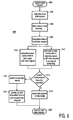
- a procedure to calculate whether to enter the disk drive system 3 in a standby mode after a data request or not is depicted in Figure 5, showing a flowchart 500 to visualize an embodiment of the method according to the invention.
- the procedure starts at a starting point 502 by the reception of a data request.
- the host 2 reads data from the disk drive system 3.
- the data read from the disk drive system 3 is stored in the host 2 in the host RAM 10 in a subsequent step 506.
- the microprocessor 8 determines the period of time to lapse until the microcontroller needs more data and a subsequent request for data is issued.
- the need for data is known over time. This may be used advantageously by calculating whether the drive system 3 should be put in the power down mode or should be left in the idle mode to save most energy.
- this is done by determining the data rate of processing the requested data.
- the requested data is an MP3 file
- the data is streamed from the host RAM 10 at a continuous bit rate.
- the amount of data in the host RAM 10 is known, as well as the bit rate of processing, it is known how much time it will take until the data in the host RAM is processed and a subsequent request for data is issued.
- the micro-controller 8 calculates the amount of power that will be consumed in the period of time determined in the previous step 508 by the disk drive system 3 when the disk drive system 3 is put in the standby mode during the period of time determined in the previous step 508.
- the power consumed during unloading and loading the head and spinning the disk down and up are added to this value, because these actions have to be performed as well when switching the disk drive system 3 in the standby mode. Consequently, the amount of power calculated in the step 510 equals the power consumed in the periods "load", "unload” and "standby” in Figure 4.
- the micro-controller calculates the amount of power that will be consumed by the disk drive system 3 in the period of time determined in the step 508 when the disk drive system 3 is left idle in the period of time determined in the step 508.
- the values determined in the step 510 and the step 512 are compared.
- the disk drive system 3 is set to the standby mode when the amount of power determined in the step 510 is larger than the amount of power determined in the step 512.
- the disk drive system 3 is left in the idle mode. In other words, the disk drive system 3 is set to or left in the most efficient mode.
- the procedure proceeds to a step 520 to power up the disk drive system 3 right before the next data request is expected. In this way, no valuable time is consumed by starting up the disk drive system 3 when the actual request arrives: in this way, the request can be served directly when it arrives at the expected time.
- the disk When the step 520 is omitted in the procedure, the disk has to be spun up at the moment of the request, which will be done automatically. As mentioned, this will provide a delay in the data transfer.
- the procedure ends in a terminator 522, waiting for the next data request.
- the procedure is most effective when as much data as possible is read in the step 504, because this will mean that more time will lapse until the next data request occurs. In this way, the drive system 3 can be put to standby for a longer time. Therefore, it is most efficient to read multiple files in one read step.
- the procedure may be executed by the circuit according to the invention, of which the host 2 is an embodiment.
- the host 2 may be comprised in a consumer electronics apparatus 600 as shown in Figure 6.
- a preferred embodiment of the apparatus according to the invention is a portable MP3 player.
- the consumer apparatus 600 comprises the host 2 ( Figure 1) and means for receiving a computer-readable disk memory 610.
- the computer-readable disk memory 610 is a hard disk drive in the Compact Flash format, known as a microdrive, which can be inserted in a slot 630.
- the computer-readable disk memory 610 is a small form factor optical disc.
- the invention may be summarized as follows:
- Consumer electronic devices that run on a battery or an accumulator- i.e particularly portable applications such as mobile phones, laptops or MPEG players or recorders-require the management of power consumption. They consist essentially of a host and a storage medium like a disk or means for receiving a storage medium like a disk drive that are coupled with an interface. Power management is very important because long battery life enhances user convenience. According to the invention, it is determined whether it is more efficient either to leave the disk drive in the idle mode or to switch the drive to standby until the next data request appears. The disk-drive is entered into the most efficient power mode. The time until the next request is determined by the host.
Landscapes
- Engineering & Computer Science (AREA)
- Theoretical Computer Science (AREA)
- Physics & Mathematics (AREA)
- General Engineering & Computer Science (AREA)
- General Physics & Mathematics (AREA)
- Power Sources (AREA)
- Signal Processing For Digital Recording And Reproducing (AREA)
- Recording Measured Values (AREA)
Abstract
Description
- The invention relates to a method of managing power consumption of a disk drive comprised by a device, the device further comprising a host, the host comprising a buffer memory and a host processor, the disk drive comprising a disk comprising data, and the disk drive being capable of operating in at least two operating modes, the two modes having different power consumption levels, the method comprising the step of loading data requested by the host processor from the disk drive into the buffer in a first operating mode of the disk drive having a first power consumption level.
- The invention further relates to a device comprising a disk drive and a host, the host comprising a buffer memory and a host processor, the disk drive comprising a disk comprising data; and the disk drive being capable of operating in at least two operating modes, the two modes having different power consumption levels, the host processor being conceived to load data from the disk drive into the buffer in a first operating mode of the disk drive having a first power consumption level.
- U.S. Patent 5,682,273 refers to disk drives used in portable computers that are battery-powered. In particular, it relates to such disk drives that include techniques for minimizing energy consumption. U.S. Patent 5,682,273 discloses a disk drive that performs power management from past disk drive access history as well as a prediction of future user demands to determine the entry and exit times of the power saving modes. This has an advantage over the current user-selectable predetermined or fixed mode entry times because the user does not know what performance and energy-consumption costs are associated with entry and exit from power saving modes. In U.S. Patent 5,682,273, the time intervals for entering a power saving mode are computed on the basis of the energy break-even times and recovery times associated with the different power saving modes as explained above.
- The disk drive of U.S. Patent 5,682,273 attempts to forecast when the next request will occur. This forecast, however, can be faulty because the hard disk must power up prematurely if the next request appears earlier. This takes time, which is not calculated, and activity in a real-time streaming consumer electronics application is disturbed or data may be lost. All of the prior art described above may be classified as systems wherein the drive attempts to predict when the following drive request will be received with varying degrees of success.
- Furthermore, further hard disk systems are known from practice. Modem hard disk systems have an option to actively put the hard disk system in one or more power save modes. This is especially advantageous for portable devices like laptop computers. However, additional power is consumed when putting the hard disk system in a power save mode and getting the hard disk system out of the power save mode when data is requested or needs to be written. This has to be taken into account when putting the drive in a power save mode.
- It is an object of the invention to provide an improved method of managing the power consumption of the disk drive.
- This object is achieved by the method according to
claim 1 and a device according toclaim 8. - The document U.S. Patent 4,984,103 issued January 9, 1991 for a "Method for Reading/Writing a Floppy Disk Drive with Buffer Memory," discloses a disk drive with a buffer for storing more information than was requested in a first operating mode by a request from a host processor and is then spun down to a second operating mode, where the second operating mode consumes less power than the first operating mode. The disk drive does not spin up again to the first operating mode until a request is received from the host processor that is not contained in the buffer.
- The document U.S. Patent 5,481,733 issued January 2, 1996 for a "Method for managing the power distributed to a disk drive in a laptop computer," discloses the quantization of predetermined periods of disk inactivity into states, which are stored in a state table in memory in a host device. Based upon a history of disk accesses by a user, the number of transitions between each pair of states is counted and stored in memory. Future periods of disk activity can be predicted and the prediction is compared to a threshold. Based upon the comparison with the threshold the disk drive is transitioned from a first operating mode to a second operating mode, where the second operating mode consumes less power than the first operating mode.
- The GB Patent Application 2,347,531 published September 6, 2000 for "Reducing dissipated energy in a device such as a hard-disk drive," discloses a method of calculating the energy expected to be saved by the device when it makes a transition from a first operating mode to a second operating mode, determining the time the device should make the transition to the second operating mode using the above calculation, and causing the device to transition to its second operating mode. Both operating modes may be power saving modes. The energy dissipated when the device makes a transition to the second operating mode and then back to the first operating mode may be compared with the energy dissipated when the device remains in the first operating mode. A distribution of past command intervals may be calculated to calculate the energy expected to be saved. This may be used to calculate a response delay time with respect to the next command. The distribution of command intervals may be updated regularly.
- The host processor controls the processes of the electronic apparatus and therefore knows the data needs of the host. In this way, the host processor knows when all data in the buffer memory has been processed and when new data is needed. With this information and the information on what amount of power is consumed when switching from the first operating mode to the second operating mode and vice versa, calculations can be made whether it is advantageous to switch to the second operating mode or not. Letting this process be controlled by the host processor instead of by the disk drive is advantageous because the host does know the data requirements of the electronic apparatus and therefore knows when data will be requested. This makes prediction obsolete and is more reliable.
- An embodiment of the invention is characterized in that the data request comprises a request for multiple files.
- Requesting multiple files and reading them all at once in the buffer memory is advantageous because buffer memory is filled up to a higher level than when only one file is read. In this way, more time will elapse before new data is needed from the disk and more power can be saved.
- The objects and the advantages of the present invention will become more readily apparent to those ordinarily skilled in the art after reviewing the following detailed description and accompanying drawings, wherein:
- Figure 1 is a block diagram showing an embodiment of the circuit according to the invention and a disk drive system;
- Figure 2 is an overview of the system showing the drive, the interface and the software running on the host system;
- Figure 3 is a diagram showing the power consumption of a prior-art hard disk drive;
- Figure 4 is a diagram showing the power consumption of a hard disk drive according to the invention;
- Figure 5 is a flowchart showing an embodiment of the method according to the invention; and
- Figure 6 shows an embodiment of the apparatus according to the invention.
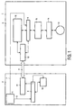
- Referring to the drawings more particularly, Figure 1 shows a block diagram with the various elements for the power reduction of a
consumer electronics system 1. Theconsumer electronics system 1 comprises ahost 2 and adisk drive system 3 that are connected by aninterface 4. In this embodiment, thepower source 5 belongs to thehost 2 and supplies themicrocontroller 6 in thestorage system 3 via abus 7. Thepower source 5 also supplies themicroprocessor 8 via anotherbus 9. - Any operation begins in the
host 2. When thehost 2 becomes aware that a data transfer is required to or from thestorage system 3, a region ofhost RAM 10 is reserved for the data transfer. Thehost 2 then sets up a table in the DMA (Direct Memory Access)controller 11 describing the host memory region that was reserved. The final host operation is to inform thestorage system 3 of the requested data operation using a standard protocol over theinterface 4. -
DMA controller 12 of thestorage system 3 handles the communication with thehost 2. Thestorage system 3 attempts to perform the required data transfer in the shortest possible time and ensures that the data is read from or written to the reserved memory region ofhost RAM 10. In thedisk drive system 3, the information is stored on amagnetic disk 13. The signal is read by using a corresponding head and amplified by the pre-amplifier 14. The read/writechannel 15 processes the signals so that the risk of an error is minimized. - The
microcontroller 6 in thestorage system 3 controls a servo-system (not shown) controlling the head and ensures that data is correctly transmitted and received over thecommon interface 4. Themicrocontroller 6 also uses buffering to improve average performance using aRAM 16. Finally, the microcontroller is also responsible for correcting any data errors as much as possible. Thehost 2 may be a general purpose computer or an embedded system, such as a consumer electronics device. Thehost 2 uses thestorage system 3 to preserve information across power removal. - Figure 2 is an overview of the system showing the
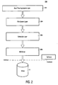
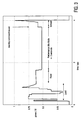
disk drive system 3 and asoftware stack 200 running on thehost system 2. The software comprises a real-time application layer 202, afile system layer 204, ascheduler layer 206 and an IDE (integrated drive electronics interface)driver 208. The decision to change power modes is made in the software-based request scheduler layer running in the memory on the processor of thehost 2. For optimal power-performance trade-off, thescheduler layer 206 has the property of being aware of both real-time data requirements and power usage. - Figure 3 shows the power trace measured on a microdrive that uses a prior art method for managing the power consumption. The trace begins and ends with the power consumption in the standby mode. After a few milliseconds, the microdrive exits the standby mode and the power trace for loading and reading is drawn. According to the prior art, the microdrive then remains fully active in a so-called performance idle mode, which means that the drive can respond immediately to the next incoming request. The trace shows that spinning the disk still draws quite a lot of energy from the power supply. In this example of the prior art, the standby command is issued internally in the disk drive after 2 seconds. When the internal standby command is issued, the unloading process begins and afterwards the standby mode is reached. In this example, the standby mode corresponds to approximately 0.06 W.
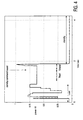
- Contrary to the power trace shown in Figure 3, the power trace of Figure 4 shows much less power consumption for the same processes. Again, the power trace begins in the standby mode that is exited for the loading and reading process. Immediately after finishing the current request-this example is a reading request-the standby command is issued and the unloading process is executed immediately after the reading process. This results in a much earlier switch of the standby mode. The loading, the reading and the unloading processes themselves consume the same power, either with the prior art method or the inventive method. Therefore, putting the drive in the standby mode for a too short period may take more energy than keeping it in the idle mode when a data request is received too soon by the drive. However, it becomes apparent that power consumption is much less if the storage system, in this example the microdrive, does not wait in an active performance idle mode before entering the standby mode.
- A procedure to calculate whether to enter the
disk drive system 3 in a standby mode after a data request or not is depicted in Figure 5, showing aflowchart 500 to visualize an embodiment of the method according to the invention. The procedure starts at astarting point 502 by the reception of a data request. Subsequently, in astep 504, thehost 2 reads data from thedisk drive system 3. The data read from thedisk drive system 3 is stored in thehost 2 in thehost RAM 10 in asubsequent step 506. In thenext step 508, themicroprocessor 8 determines the period of time to lapse until the microcontroller needs more data and a subsequent request for data is issued. - Especially when streaming data, for example an MP3 file, from the
disk drive system 3 to thehost 2, the need for data is known over time. This may be used advantageously by calculating whether thedrive system 3 should be put in the power down mode or should be left in the idle mode to save most energy. - In a preferred embodiment of the invention, this is done by determining the data rate of processing the requested data. When the requested data is an MP3 file, the data is streamed from the
host RAM 10 at a continuous bit rate. When the amount of data in thehost RAM 10 is known, as well as the bit rate of processing, it is known how much time it will take until the data in the host RAM is processed and a subsequent request for data is issued. - In the
next step 510, themicro-controller 8 calculates the amount of power that will be consumed in the period of time determined in theprevious step 508 by thedisk drive system 3 when thedisk drive system 3 is put in the standby mode during the period of time determined in theprevious step 508. The power consumed during unloading and loading the head and spinning the disk down and up are added to this value, because these actions have to be performed as well when switching thedisk drive system 3 in the standby mode. Consequently, the amount of power calculated in thestep 510 equals the power consumed in the periods "load", "unload" and "standby" in Figure 4. - In the
step 512, the micro-controller calculates the amount of power that will be consumed by thedisk drive system 3 in the period of time determined in thestep 508 when thedisk drive system 3 is left idle in the period of time determined in thestep 508. - In the
decision 514, the values determined in thestep 510 and thestep 512 are compared. Depending on the outcome, thedisk drive system 3 is set to the standby mode when the amount of power determined in thestep 510 is larger than the amount of power determined in thestep 512. When the amount of power determined in thestep 510 is less than the amount of power determined in thestep 512, thedisk drive system 3 is left in the idle mode. In other words, thedisk drive system 3 is set to or left in the most efficient mode. - When the procedure has branched to the
step 516 and thedisk drive system 3 has been set to the standby mode, the procedure proceeds to astep 520 to power up thedisk drive system 3 right before the next data request is expected. In this way, no valuable time is consumed by starting up thedisk drive system 3 when the actual request arrives: in this way, the request can be served directly when it arrives at the expected time. - When the
step 520 is omitted in the procedure, the disk has to be spun up at the moment of the request, which will be done automatically. As mentioned, this will provide a delay in the data transfer. - The procedure ends in a
terminator 522, waiting for the next data request. - The procedure is most effective when as much data as possible is read in the
step 504, because this will mean that more time will lapse until the next data request occurs. In this way, thedrive system 3 can be put to standby for a longer time. Therefore, it is most efficient to read multiple files in one read step. - The procedure may be executed by the circuit according to the invention, of which the
host 2 is an embodiment. - The
host 2 may be comprised in aconsumer electronics apparatus 600 as shown in Figure 6. A preferred embodiment of the apparatus according to the invention is a portable MP3 player. Theconsumer apparatus 600 comprises the host 2 (Figure 1) and means for receiving a computer-readable disk memory 610. In the presented embodiment of the apparatus according to the invention, the computer-readable disk memory 610 is a hard disk drive in the Compact Flash format, known as a microdrive, which can be inserted in aslot 630. However, in a further embodiment, the computer-readable disk memory 610 is a small form factor optical disc. The person skilled in the art can also name numerous other embodiments like various types of harddisk drives and optical discs; the scope of the invention is not limited to the computer-readable disk memory 610 as presented in this description of the preferred embodiments of the invention. Connected to theapparatus 600 is a pair ofheadphones 620 to listen to audio information stored on the computerreadable disk memory 610. - The invention may be summarized as follows:
- Consumer electronic devices that run on a battery or an accumulator- i.e particularly portable applications such as mobile phones, laptops or MPEG players or recorders-require the management of power consumption. They consist essentially of a host and a storage medium like a disk or means for receiving a storage medium like a disk drive that are coupled with an interface. Power management is very important because long battery life enhances user convenience. According to the invention, it is determined whether it is more efficient either to leave the disk drive in the idle mode or to switch the drive to standby until the next data request appears. The disk-drive is entered into the most efficient power mode. The time until the next request is determined by the host.
Claims (8)
- A method of managing power consumption of a disk drive (3) comprised by a device (600), the device further comprising a host (2), the host comprising a buffer (10) and a host processor (8);
the disk drive comprising a disk memory (13) comprising data; and the disk drive being capable of operating in at least two operating modes, the two modes having different power consumption levels, the method comprising the step of loading data requested by the host processor from the disk drive into the buffer in a first operating mode of the disk drive having a first power consumption level;
the method further comprises the following steps:a) determining a period of time to lapse from the moment the data requested is loaded into the buffer until the data read into the buffer in the previous step is processed;b) determining a first amount of power that will be consumed by the disk drive during the period of time when the disk drive is left in the first operating mode during said period of time;c) determining a second amount of power that will be consumed by the disk drive:i.) during the period of time when the disk drive is entered into the second operating mode having a second level of power consumption, the second level of power consumption being lower than the first level of power consumption andii.) for switching from the first operating mode to the second operating mode andiii.) for switching from the second operating mode to the first operating mode; andd) entering the disk drive into the second operating mode when the second amount of power is less than the first amount of power. - A method as claimed in claim 1, wherein determining said period of time comprises the following steps:a) determining a processing rate at which the host processes the data stored in the bufferb) determining an amount of data stored in the bufferc) multiplying the processing rate with the amount of data stored in the buffer.
- A method as claimed in claim 1, wherein the data request comprises a request for multiple files.
- A method as claimed in claim 2, wherein the requested data comprises at least a part of the stream of audiovisual data and the processing rate is the streaming rate of the stream of audiovisual data.
- A method as claimed in claim 1, wherein the disk memory is an optical disc.
- A method as claimed in claim 1, wherein the disk memory is a hard disk.
- A method as claimed in claim 1, further comprising the step of switching from the second operating mode to the first operating mode when the period of time has elapsed.
- A device (600) comprising a disk drive (3) and a host (2), the host comprising a buffer (10) and a host processor (8);
the disk drive comprising a disk (13) comprising data; and the disk drive being capable of operating in at least two operating modes, the two modes having different power consumption levels, the host processor being conceived to load data from the disk drive into the buffer in a first operating mode of the disk drive having a first power consumption level;
the host processor is further conceived to:a) determine a period of time until the data in the buffer memory is processed;b) determine a first amount of power that will be consumed by the disk drive during the period of time when the disk drive is left in the first operating mode during said period of time;c) determine a second amount of power that will be consumed by the disk drive:i.) during the period of time when the disk drive is entered into the second operating mode having a second level of power consumption, the second level of power consumption being lower than the first level of power consumption andii.) while switching from the first operating mode to the second operating mode andiii.) while switching from the second operating mode to the first operating mode; andd) enter the disk drive into the second operating mode when the second amount of power is less than the first amount of power.
Priority Applications (1)
| Application Number | Priority Date | Filing Date | Title |
|---|---|---|---|
| EP03793949A EP1540451B1 (en) | 2002-09-09 | 2003-08-08 | Method and apparatus for managing power consumption of a disk drive |
Applications Claiming Priority (4)
| Application Number | Priority Date | Filing Date | Title |
|---|---|---|---|
| EP02078655 | 2002-09-09 | ||
| EP02078655 | 2002-09-09 | ||
| EP03793949A EP1540451B1 (en) | 2002-09-09 | 2003-08-08 | Method and apparatus for managing power consumption of a disk drive |
| PCT/IB2003/003632 WO2004023279A2 (en) | 2002-09-09 | 2003-08-08 | Method and apparatus for managing power consumption of a disk drive |
Publications (2)
| Publication Number | Publication Date |
|---|---|
| EP1540451A2 EP1540451A2 (en) | 2005-06-15 |
| EP1540451B1 true EP1540451B1 (en) | 2007-03-21 |
Family
ID=31970394
Family Applications (1)
| Application Number | Title | Priority Date | Filing Date |
|---|---|---|---|
| EP03793949A Expired - Lifetime EP1540451B1 (en) | 2002-09-09 | 2003-08-08 | Method and apparatus for managing power consumption of a disk drive |
Country Status (10)
| Country | Link |
|---|---|
| US (1) | US7075744B2 (en) |
| EP (1) | EP1540451B1 (en) |
| JP (1) | JP2005538444A (en) |
| KR (1) | KR20050038650A (en) |
| CN (1) | CN100351744C (en) |
| AT (1) | ATE357689T1 (en) |
| AU (1) | AU2003259399A1 (en) |
| DE (1) | DE60312703T2 (en) |
| TW (1) | TW200421288A (en) |
| WO (1) | WO2004023279A2 (en) |
Families Citing this family (25)
| Publication number | Priority date | Publication date | Assignee | Title |
|---|---|---|---|---|
| WO2004049147A1 (en) * | 2002-11-25 | 2004-06-10 | Fujitsu Limited | Power-saving control system and power-saving control method |
| JP4406000B2 (en) * | 2003-01-06 | 2010-01-27 | コーニンクレッカ フィリップス エレクトロニクス エヌ ヴィ | Energy efficient disk scheduling for mobile applications: Adaptive extension of disk standby time |
| US7634615B2 (en) * | 2004-06-10 | 2009-12-15 | Marvell World Trade Ltd. | Adaptive storage system |
| JP2006164012A (en) * | 2004-12-09 | 2006-06-22 | Hitachi Global Storage Technologies Netherlands Bv | Data storage device and control method for power save mode |
| US20060265617A1 (en) * | 2005-05-18 | 2006-11-23 | Priborsky Anthony L | Power management in a system having multiple power modes |
| KR100780939B1 (en) * | 2005-06-29 | 2007-12-03 | 삼성전자주식회사 | Unload standby time controlling method and apparatus for the same |
| CN101371213B (en) * | 2005-12-06 | 2012-03-14 | Arm有限公司 | Energy management |
| US7443627B1 (en) * | 2006-03-07 | 2008-10-28 | Marvell International Ltd. | Lowest power mode for a mobile drive |
| US8099548B2 (en) * | 2006-03-23 | 2012-01-17 | Microsoft Corporation | Power efficient media playback on general purpose portable devices |
| US8171312B2 (en) * | 2006-07-05 | 2012-05-01 | Canon Kabushiki Kaisha | Recording apparatus and method for controlling the recording apparatus |
| JP4837780B2 (en) * | 2006-07-28 | 2011-12-14 | アーム・リミテッド | Power management in data processing devices with master and slave |
| JP2008058404A (en) * | 2006-08-29 | 2008-03-13 | Matsushita Electric Ind Co Ltd | Music reproducing device and music reproducing terminal |
| US7640412B2 (en) * | 2007-01-04 | 2009-12-29 | Hitachi Global Storage Technologies Netherlands, B.V. | Techniques for improving the reliability of file systems |
| GB0707147D0 (en) * | 2007-04-13 | 2007-05-23 | Basic Device Ltd | Radiators |
| US8635491B2 (en) * | 2007-09-28 | 2014-01-21 | Seagate Technology Llc | Storage device maintenance in a portable device based on a power event |
| JP2010134858A (en) * | 2008-12-08 | 2010-06-17 | Renesas Electronics Corp | Data processing circuit |
| US8090415B2 (en) * | 2008-12-12 | 2012-01-03 | Sony Ericsson Mobile Communications Ab | Intelligent battery warning system |
| US8245064B2 (en) * | 2009-06-16 | 2012-08-14 | Seagate Technology Llc | Power conservation during a power mode transition |
| US8595522B2 (en) * | 2010-09-30 | 2013-11-26 | Intel Corporation | Monitoring transaction requests using a policy engine within a storage drive driver to change power capability and latency settings for a storage drive |
| US8743502B1 (en) | 2010-12-17 | 2014-06-03 | Western Digital Technologies, Inc. | Disk drive spinning down disk to a spin rate based on spin-up parameter |
| US8781294B2 (en) * | 2012-11-30 | 2014-07-15 | Seagate Technology Llc | Media content caching |
| US9195293B1 (en) | 2013-05-03 | 2015-11-24 | Western Digital Technologies, Inc. | User controlled data storage device power and performance settings |
| US9372529B1 (en) * | 2013-05-30 | 2016-06-21 | Western Digital Technologies, Inc. | Storage device selectively utilizing power from a host and power from an AC adapter |
| US9524015B2 (en) * | 2014-02-19 | 2016-12-20 | Western Digital Technologies, Inc. | Device optimized power management |
| CN105988726B (en) * | 2014-10-31 | 2019-06-11 | 株式会社东芝 | Storage device and for using power supply invalid signals method |
Family Cites Families (23)
| Publication number | Priority date | Publication date | Assignee | Title |
|---|---|---|---|---|
| US4984103A (en) * | 1987-12-07 | 1991-01-08 | Fujitsu America, Inc. | Method for reading/writing for a floppy disc drive with buffer memory |
| US4933795A (en) * | 1987-12-07 | 1990-06-12 | Fujitsu America, Inc. | Floppy disc read and write head having two separate read and write cores for multiple track density and recording frequencies |
| JP2858542B2 (en) * | 1994-06-03 | 1999-02-17 | インターナショナル・ビジネス・マシーンズ・コーポレイション | Method and apparatus for reducing power consumption of a computer disk drive |
| US5481733A (en) * | 1994-06-15 | 1996-01-02 | Panasonic Technologies, Inc. | Method for managing the power distributed to a disk drive in a laptop computer |
| WO1996010249A1 (en) | 1994-09-27 | 1996-04-04 | Maxtor Corporation | New mode for power-down |
| US6092209A (en) * | 1994-10-04 | 2000-07-18 | Intel Corporation | Method and apparatus for managing power consumption of peripheral devices of personal computers |
| US5574920A (en) * | 1994-10-25 | 1996-11-12 | Microsoft Corporation | Method for controlling power down of a hard disk drive in a computer |
| TW279228B (en) * | 1994-12-16 | 1996-06-21 | Detutsche Thomson Brandt Gmbh | |
| US5682273A (en) * | 1995-06-30 | 1997-10-28 | International Business Machines Corporation | Disk drive for portable computer with adaptive demand-driven power management |
| GB2310513B (en) * | 1996-02-20 | 2000-02-16 | Ibm | Computer with reduced power consumption |
| US5926640A (en) * | 1996-11-01 | 1999-07-20 | Digital Equipment Corporation | Skipping clock interrupts during system inactivity to reduce power consumption |
| JPH11144373A (en) * | 1997-11-13 | 1999-05-28 | Matsushita Electric Ind Co Ltd | Optical disk reproducing device |
| JP3819166B2 (en) * | 1998-11-27 | 2006-09-06 | ヒタチグローバルストレージテクノロジーズネザーランドビーブイ | Energy consumption reduction method |
| JP3860394B2 (en) * | 2000-06-20 | 2006-12-20 | 株式会社リコー | Information reproducing method and information reproducing apparatus |
| JP2002109820A (en) * | 2000-09-29 | 2002-04-12 | Fujitsu Ltd | Information storage device |
| US6590730B2 (en) * | 2001-01-05 | 2003-07-08 | Creative Technology Ltd. | System for managing power in a portable music player |
| US6892313B1 (en) * | 2001-06-21 | 2005-05-10 | Western Digital Technologies, Inc. | Method for predictive power management for operating a disk drive in a mobile device to optimize power usage |
| US6928039B2 (en) * | 2001-06-29 | 2005-08-09 | Texas Instruments Incorporated | Method and apparatus for the reduction of power consumption in a compact disc player |
| US20030067847A1 (en) * | 2001-10-05 | 2003-04-10 | Silvester Kelan C. | Reducing power consumption of rotating disk storage devices |
| US6934812B1 (en) * | 2001-10-22 | 2005-08-23 | Apple Computer, Inc. | Media player with instant play capability |
| US20040015731A1 (en) * | 2002-07-16 | 2004-01-22 | International Business Machines Corporation | Intelligent data management fo hard disk drive |
| JP2004062928A (en) * | 2002-07-25 | 2004-02-26 | Hitachi Ltd | Magnetic disk drive and storage system |
| KR100519611B1 (en) * | 2002-10-25 | 2005-10-10 | 학교법인 한양학원 | low-power data retrival Method and device |
-
2003
- 2003-08-08 JP JP2004533716A patent/JP2005538444A/en not_active Withdrawn
- 2003-08-08 EP EP03793949A patent/EP1540451B1/en not_active Expired - Lifetime
- 2003-08-08 KR KR1020057004064A patent/KR20050038650A/en not_active Application Discontinuation
- 2003-08-08 AU AU2003259399A patent/AU2003259399A1/en not_active Abandoned
- 2003-08-08 CN CNB038213230A patent/CN100351744C/en not_active Expired - Fee Related
- 2003-08-08 WO PCT/IB2003/003632 patent/WO2004023279A2/en active IP Right Grant
- 2003-08-08 AT AT03793949T patent/ATE357689T1/en not_active IP Right Cessation
- 2003-08-08 DE DE60312703T patent/DE60312703T2/en not_active Expired - Lifetime
- 2003-08-08 US US10/526,872 patent/US7075744B2/en not_active Expired - Fee Related
- 2003-09-05 TW TW092124626A patent/TW200421288A/en unknown
Also Published As
| Publication number | Publication date |
|---|---|
| JP2005538444A (en) | 2005-12-15 |
| CN1682177A (en) | 2005-10-12 |
| WO2004023279A2 (en) | 2004-03-18 |
| DE60312703T2 (en) | 2007-12-06 |
| ATE357689T1 (en) | 2007-04-15 |
| US20050251696A1 (en) | 2005-11-10 |
| AU2003259399A1 (en) | 2004-03-29 |
| US7075744B2 (en) | 2006-07-11 |
| CN100351744C (en) | 2007-11-28 |
| TW200421288A (en) | 2004-10-16 |
| KR20050038650A (en) | 2005-04-27 |
| EP1540451A2 (en) | 2005-06-15 |
| DE60312703D1 (en) | 2007-05-03 |
| WO2004023279A3 (en) | 2004-09-02 |
Similar Documents
| Publication | Publication Date | Title |
|---|---|---|
| EP1540451B1 (en) | Method and apparatus for managing power consumption of a disk drive | |
| EP1605455B1 (en) | RAID with high power and low power disk drives | |
| US5544138A (en) | Adaptive system for optimizing disk drive power consumption | |
| EP2049968B1 (en) | Adaptive storage system including hard disk drive with flash interface | |
| US8327177B2 (en) | System and method for information handling system storage device power consumption management | |
| EP2016476B1 (en) | Adaptive storage system including hard disk drive with flash interface | |
| JP4061492B2 (en) | Information processing apparatus and power consumption control method | |
| US20040015731A1 (en) | Intelligent data management fo hard disk drive | |
| US8286018B2 (en) | Power management in data storage device determining utilization of a control circuit by its rate of command processing | |
| EP1621972A2 (en) | Low power computer with main and auxiliary processors | |
| US20110047316A1 (en) | Solid state memory device power optimization | |
| US8495400B2 (en) | Energy-efficient transitioning among device operating modes | |
| WO2008103359A1 (en) | Externally removable non-volatile semiconductor memory module for hard disk drives | |
| WO2008007273A2 (en) | A device and a method for managing power consumption of a plurality of data processing units | |
| US6590730B2 (en) | System for managing power in a portable music player | |
| EP1855181A2 (en) | System with high power and low power processors and thread transfer | |
| US7093149B2 (en) | Tiered secondary memory architecture to reduce power consumption in a portable computer system | |
| US20090240839A1 (en) | Data storage device | |
| KR20080060649A (en) | Apparatus and method for data processing | |
| US20060274622A1 (en) | Motor power controller for a disk drive, disk drive comprising a motor power controller and method for controlling the motor power of a disk drive | |
| JPH11306664A (en) | External storage device | |
| US20040193297A1 (en) | Using a digital computer as a low power flashmedia player |
Legal Events
| Date | Code | Title | Description |
|---|---|---|---|
| PUAI | Public reference made under article 153(3) epc to a published international application that has entered the european phase |
Free format text: ORIGINAL CODE: 0009012 |
|
| 17P | Request for examination filed |
Effective date: 20050411 |
|
| AK | Designated contracting states |
Kind code of ref document: A2 Designated state(s): AT BE BG CH CY CZ DE DK EE ES FI FR GB GR HU IE IT LI LU MC NL PT RO SE SI SK TR |
|
| AX | Request for extension of the european patent |
Extension state: AL LT LV MK |
|
| DAX | Request for extension of the european patent (deleted) | ||
| GRAP | Despatch of communication of intention to grant a patent |
Free format text: ORIGINAL CODE: EPIDOSNIGR1 |
|
| RTI1 | Title (correction) |
Free format text: METHOD AND APPARATUS FOR MANAGING POWER CONSUMPTION OF A DISK DRIVE |
|
| GRAS | Grant fee paid |
Free format text: ORIGINAL CODE: EPIDOSNIGR3 |
|
| GRAA | (expected) grant |
Free format text: ORIGINAL CODE: 0009210 |
|
| AK | Designated contracting states |
Kind code of ref document: B1 Designated state(s): AT BE BG CH CY CZ DE DK EE ES FI FR GB GR HU IE IT LI LU MC NL PT RO SE SI SK TR |
|
| PG25 | Lapsed in a contracting state [announced via postgrant information from national office to epo] |
Ref country code: NL Free format text: LAPSE BECAUSE OF FAILURE TO SUBMIT A TRANSLATION OF THE DESCRIPTION OR TO PAY THE FEE WITHIN THE PRESCRIBED TIME-LIMIT Effective date: 20070321 Ref country code: FI Free format text: LAPSE BECAUSE OF FAILURE TO SUBMIT A TRANSLATION OF THE DESCRIPTION OR TO PAY THE FEE WITHIN THE PRESCRIBED TIME-LIMIT Effective date: 20070321 Ref country code: BE Free format text: LAPSE BECAUSE OF FAILURE TO SUBMIT A TRANSLATION OF THE DESCRIPTION OR TO PAY THE FEE WITHIN THE PRESCRIBED TIME-LIMIT Effective date: 20070321 Ref country code: AT Free format text: LAPSE BECAUSE OF FAILURE TO SUBMIT A TRANSLATION OF THE DESCRIPTION OR TO PAY THE FEE WITHIN THE PRESCRIBED TIME-LIMIT Effective date: 20070321 Ref country code: CH Free format text: LAPSE BECAUSE OF FAILURE TO SUBMIT A TRANSLATION OF THE DESCRIPTION OR TO PAY THE FEE WITHIN THE PRESCRIBED TIME-LIMIT Effective date: 20070321 Ref country code: SI Free format text: LAPSE BECAUSE OF FAILURE TO SUBMIT A TRANSLATION OF THE DESCRIPTION OR TO PAY THE FEE WITHIN THE PRESCRIBED TIME-LIMIT Effective date: 20070321 Ref country code: LI Free format text: LAPSE BECAUSE OF FAILURE TO SUBMIT A TRANSLATION OF THE DESCRIPTION OR TO PAY THE FEE WITHIN THE PRESCRIBED TIME-LIMIT Effective date: 20070321 |
|
| REG | Reference to a national code |
Ref country code: GB Ref legal event code: FG4D |
|
| REG | Reference to a national code |
Ref country code: CH Ref legal event code: EP |
|
| REF | Corresponds to: |
Ref document number: 60312703 Country of ref document: DE Date of ref document: 20070503 Kind code of ref document: P |
|
| REG | Reference to a national code |
Ref country code: IE Ref legal event code: FG4D |
|
| PG25 | Lapsed in a contracting state [announced via postgrant information from national office to epo] |
Ref country code: SE Free format text: LAPSE BECAUSE OF FAILURE TO SUBMIT A TRANSLATION OF THE DESCRIPTION OR TO PAY THE FEE WITHIN THE PRESCRIBED TIME-LIMIT Effective date: 20070621 |
|
| PG25 | Lapsed in a contracting state [announced via postgrant information from national office to epo] |
Ref country code: ES Free format text: LAPSE BECAUSE OF FAILURE TO SUBMIT A TRANSLATION OF THE DESCRIPTION OR TO PAY THE FEE WITHIN THE PRESCRIBED TIME-LIMIT Effective date: 20070702 |
|
| PG25 | Lapsed in a contracting state [announced via postgrant information from national office to epo] |
Ref country code: PT Free format text: LAPSE BECAUSE OF FAILURE TO SUBMIT A TRANSLATION OF THE DESCRIPTION OR TO PAY THE FEE WITHIN THE PRESCRIBED TIME-LIMIT Effective date: 20070821 |
|
| ET | Fr: translation filed | ||
| REG | Reference to a national code |
Ref country code: CH Ref legal event code: PL |
|
| NLV1 | Nl: lapsed or annulled due to failure to fulfill the requirements of art. 29p and 29m of the patents act | ||
| PG25 | Lapsed in a contracting state [announced via postgrant information from national office to epo] |
Ref country code: SK Free format text: LAPSE BECAUSE OF FAILURE TO SUBMIT A TRANSLATION OF THE DESCRIPTION OR TO PAY THE FEE WITHIN THE PRESCRIBED TIME-LIMIT Effective date: 20070321 |
|
| PG25 | Lapsed in a contracting state [announced via postgrant information from national office to epo] |
Ref country code: CZ Free format text: LAPSE BECAUSE OF FAILURE TO SUBMIT A TRANSLATION OF THE DESCRIPTION OR TO PAY THE FEE WITHIN THE PRESCRIBED TIME-LIMIT Effective date: 20070321 Ref country code: RO Free format text: LAPSE BECAUSE OF FAILURE TO SUBMIT A TRANSLATION OF THE DESCRIPTION OR TO PAY THE FEE WITHIN THE PRESCRIBED TIME-LIMIT Effective date: 20070321 |
|
| PLBE | No opposition filed within time limit |
Free format text: ORIGINAL CODE: 0009261 |
|
| STAA | Information on the status of an ep patent application or granted ep patent |
Free format text: STATUS: NO OPPOSITION FILED WITHIN TIME LIMIT |
|
| PG25 | Lapsed in a contracting state [announced via postgrant information from national office to epo] |
Ref country code: DK Free format text: LAPSE BECAUSE OF FAILURE TO SUBMIT A TRANSLATION OF THE DESCRIPTION OR TO PAY THE FEE WITHIN THE PRESCRIBED TIME-LIMIT Effective date: 20070321 |
|
| 26N | No opposition filed |
Effective date: 20071227 |
|
| PG25 | Lapsed in a contracting state [announced via postgrant information from national office to epo] |
Ref country code: GR Free format text: LAPSE BECAUSE OF FAILURE TO SUBMIT A TRANSLATION OF THE DESCRIPTION OR TO PAY THE FEE WITHIN THE PRESCRIBED TIME-LIMIT Effective date: 20070622 Ref country code: IT Free format text: LAPSE BECAUSE OF FAILURE TO SUBMIT A TRANSLATION OF THE DESCRIPTION OR TO PAY THE FEE WITHIN THE PRESCRIBED TIME-LIMIT Effective date: 20070321 Ref country code: MC Free format text: LAPSE BECAUSE OF NON-PAYMENT OF DUE FEES Effective date: 20070831 |
|
| PG25 | Lapsed in a contracting state [announced via postgrant information from national office to epo] |
Ref country code: IE Free format text: LAPSE BECAUSE OF NON-PAYMENT OF DUE FEES Effective date: 20070808 |
|
| PG25 | Lapsed in a contracting state [announced via postgrant information from national office to epo] |
Ref country code: EE Free format text: LAPSE BECAUSE OF FAILURE TO SUBMIT A TRANSLATION OF THE DESCRIPTION OR TO PAY THE FEE WITHIN THE PRESCRIBED TIME-LIMIT Effective date: 20070321 |
|
| PG25 | Lapsed in a contracting state [announced via postgrant information from national office to epo] |
Ref country code: CY Free format text: LAPSE BECAUSE OF FAILURE TO SUBMIT A TRANSLATION OF THE DESCRIPTION OR TO PAY THE FEE WITHIN THE PRESCRIBED TIME-LIMIT Effective date: 20070321 |
|
| PG25 | Lapsed in a contracting state [announced via postgrant information from national office to epo] |
Ref country code: BG Free format text: LAPSE BECAUSE OF FAILURE TO SUBMIT A TRANSLATION OF THE DESCRIPTION OR TO PAY THE FEE WITHIN THE PRESCRIBED TIME-LIMIT Effective date: 20070621 Ref country code: LU Free format text: LAPSE BECAUSE OF NON-PAYMENT OF DUE FEES Effective date: 20070808 |
|
| PG25 | Lapsed in a contracting state [announced via postgrant information from national office to epo] |
Ref country code: HU Free format text: LAPSE BECAUSE OF FAILURE TO SUBMIT A TRANSLATION OF THE DESCRIPTION OR TO PAY THE FEE WITHIN THE PRESCRIBED TIME-LIMIT Effective date: 20070922 Ref country code: TR Free format text: LAPSE BECAUSE OF FAILURE TO SUBMIT A TRANSLATION OF THE DESCRIPTION OR TO PAY THE FEE WITHIN THE PRESCRIBED TIME-LIMIT Effective date: 20070321 |
|
| PGFP | Annual fee paid to national office [announced via postgrant information from national office to epo] |
Ref country code: GB Payment date: 20090901 Year of fee payment: 7 |
|
| PGFP | Annual fee paid to national office [announced via postgrant information from national office to epo] |
Ref country code: DE Payment date: 20091027 Year of fee payment: 7 |
|
| GBPC | Gb: european patent ceased through non-payment of renewal fee |
Effective date: 20100808 |
|
| REG | Reference to a national code |
Ref country code: FR Ref legal event code: ST Effective date: 20110502 |
|
| REG | Reference to a national code |
Ref country code: DE Ref legal event code: R119 Ref document number: 60312703 Country of ref document: DE Effective date: 20110301 |
|
| PG25 | Lapsed in a contracting state [announced via postgrant information from national office to epo] |
Ref country code: DE Free format text: LAPSE BECAUSE OF NON-PAYMENT OF DUE FEES Effective date: 20110301 Ref country code: FR Free format text: LAPSE BECAUSE OF NON-PAYMENT OF DUE FEES Effective date: 20100831 |
|
| PG25 | Lapsed in a contracting state [announced via postgrant information from national office to epo] |
Ref country code: GB Free format text: LAPSE BECAUSE OF NON-PAYMENT OF DUE FEES Effective date: 20100808 |
|
| PGFP | Annual fee paid to national office [announced via postgrant information from national office to epo] |
Ref country code: FR Payment date: 20090915 Year of fee payment: 7 |