EP1540411B1 - Rfid security device for optical disc - Google Patents
Rfid security device for optical disc Download PDFInfo
- Publication number
- EP1540411B1 EP1540411B1 EP03748409A EP03748409A EP1540411B1 EP 1540411 B1 EP1540411 B1 EP 1540411B1 EP 03748409 A EP03748409 A EP 03748409A EP 03748409 A EP03748409 A EP 03748409A EP 1540411 B1 EP1540411 B1 EP 1540411B1
- Authority
- EP
- European Patent Office
- Prior art keywords
- optical disc
- optical
- layer
- content
- rfid tag
- Prior art date
- Legal status (The legal status is an assumption and is not a legal conclusion. Google has not performed a legal analysis and makes no representation as to the accuracy of the status listed.)
- Expired - Lifetime
Links
- 230000003287 optical effect Effects 0.000 title claims abstract description 317
- 239000003607 modifier Substances 0.000 claims abstract description 86
- 238000000034 method Methods 0.000 claims description 66
- 239000000463 material Substances 0.000 claims description 28
- 230000008859 change Effects 0.000 claims description 15
- 239000004973 liquid crystal related substance Substances 0.000 claims description 11
- 230000009977 dual effect Effects 0.000 claims description 2
- 230000002401 inhibitory effect Effects 0.000 claims 2
- 230000000977 initiatory effect Effects 0.000 claims 1
- XAGFODPZIPBFFR-UHFFFAOYSA-N aluminium Chemical compound [Al] XAGFODPZIPBFFR-UHFFFAOYSA-N 0.000 description 9
- 229910052782 aluminium Inorganic materials 0.000 description 9
- 239000004411 aluminium Substances 0.000 description 9
- 230000000694 effects Effects 0.000 description 6
- 239000003990 capacitor Substances 0.000 description 4
- 238000009434 installation Methods 0.000 description 4
- 230000008569 process Effects 0.000 description 4
- 238000004891 communication Methods 0.000 description 3
- 239000004417 polycarbonate Substances 0.000 description 3
- 229920000515 polycarbonate Polymers 0.000 description 3
- 238000013475 authorization Methods 0.000 description 2
- 230000006870 function Effects 0.000 description 2
- 230000006872 improvement Effects 0.000 description 2
- 230000007246 mechanism Effects 0.000 description 2
- 238000012986 modification Methods 0.000 description 2
- 230000004048 modification Effects 0.000 description 2
- 230000000007 visual effect Effects 0.000 description 2
- KRHYYFGTRYWZRS-UHFFFAOYSA-M Fluoride anion Chemical compound [F-] KRHYYFGTRYWZRS-UHFFFAOYSA-M 0.000 description 1
- 229910052765 Lutetium Inorganic materials 0.000 description 1
- XOJVVFBFDXDTEG-UHFFFAOYSA-N Norphytane Natural products CC(C)CCCC(C)CCCC(C)CCCC(C)C XOJVVFBFDXDTEG-UHFFFAOYSA-N 0.000 description 1
- 230000004913 activation Effects 0.000 description 1
- 229910021417 amorphous silicon Inorganic materials 0.000 description 1
- 230000006399 behavior Effects 0.000 description 1
- 230000001364 causal effect Effects 0.000 description 1
- 238000007796 conventional method Methods 0.000 description 1
- 230000008878 coupling Effects 0.000 description 1
- 238000010168 coupling process Methods 0.000 description 1
- 238000005859 coupling reaction Methods 0.000 description 1
- 230000005672 electromagnetic field Effects 0.000 description 1
- 238000005516 engineering process Methods 0.000 description 1
- 238000005286 illumination Methods 0.000 description 1
- 230000001939 inductive effect Effects 0.000 description 1
- 230000003993 interaction Effects 0.000 description 1
- OHSVLFRHMCKCQY-UHFFFAOYSA-N lutetium atom Chemical compound [Lu] OHSVLFRHMCKCQY-UHFFFAOYSA-N 0.000 description 1
- 238000004519 manufacturing process Methods 0.000 description 1
- 239000002985 plastic film Substances 0.000 description 1
- 229920006255 plastic film Polymers 0.000 description 1
- 230000010287 polarization Effects 0.000 description 1
- 238000012545 processing Methods 0.000 description 1
- 238000011084 recovery Methods 0.000 description 1
- 230000003252 repetitive effect Effects 0.000 description 1
- 230000004044 response Effects 0.000 description 1
- 239000004065 semiconductor Substances 0.000 description 1
- 230000007704 transition Effects 0.000 description 1
- 230000001960 triggered effect Effects 0.000 description 1
- 210000003462 vein Anatomy 0.000 description 1
- 229920002554 vinyl polymer Polymers 0.000 description 1
Images


Classifications
-
- G—PHYSICS
- G11—INFORMATION STORAGE
- G11B—INFORMATION STORAGE BASED ON RELATIVE MOVEMENT BETWEEN RECORD CARRIER AND TRANSDUCER
- G11B20/00—Signal processing not specific to the method of recording or reproducing; Circuits therefor
- G11B20/10—Digital recording or reproducing
-
- G—PHYSICS
- G11—INFORMATION STORAGE
- G11B—INFORMATION STORAGE BASED ON RELATIVE MOVEMENT BETWEEN RECORD CARRIER AND TRANSDUCER
- G11B23/00—Record carriers not specific to the method of recording or reproducing; Accessories, e.g. containers, specially adapted for co-operation with the recording or reproducing apparatus ; Intermediate mediums; Apparatus or processes specially adapted for their manufacture
- G11B23/0014—Record carriers not specific to the method of recording or reproducing; Accessories, e.g. containers, specially adapted for co-operation with the recording or reproducing apparatus ; Intermediate mediums; Apparatus or processes specially adapted for their manufacture record carriers not specifically of filamentary or web form
- G11B23/0021—Record carriers not specific to the method of recording or reproducing; Accessories, e.g. containers, specially adapted for co-operation with the recording or reproducing apparatus ; Intermediate mediums; Apparatus or processes specially adapted for their manufacture record carriers not specifically of filamentary or web form discs
- G11B23/0028—Details
- G11B23/0035—Details means incorporated in the disc, e.g. hub, to enable its guiding, loading or driving
- G11B23/0042—Details means incorporated in the disc, e.g. hub, to enable its guiding, loading or driving with provision for auxiliary features
-
- G—PHYSICS
- G02—OPTICS
- G02F—OPTICAL DEVICES OR ARRANGEMENTS FOR THE CONTROL OF LIGHT BY MODIFICATION OF THE OPTICAL PROPERTIES OF THE MEDIA OF THE ELEMENTS INVOLVED THEREIN; NON-LINEAR OPTICS; FREQUENCY-CHANGING OF LIGHT; OPTICAL LOGIC ELEMENTS; OPTICAL ANALOGUE/DIGITAL CONVERTERS
- G02F1/00—Devices or arrangements for the control of the intensity, colour, phase, polarisation or direction of light arriving from an independent light source, e.g. switching, gating or modulating; Non-linear optics
- G02F1/01—Devices or arrangements for the control of the intensity, colour, phase, polarisation or direction of light arriving from an independent light source, e.g. switching, gating or modulating; Non-linear optics for the control of the intensity, phase, polarisation or colour
- G02F1/13—Devices or arrangements for the control of the intensity, colour, phase, polarisation or direction of light arriving from an independent light source, e.g. switching, gating or modulating; Non-linear optics for the control of the intensity, phase, polarisation or colour based on liquid crystals, e.g. single liquid crystal display cells
-
- G—PHYSICS
- G06—COMPUTING; CALCULATING OR COUNTING
- G06K—GRAPHICAL DATA READING; PRESENTATION OF DATA; RECORD CARRIERS; HANDLING RECORD CARRIERS
- G06K19/00—Record carriers for use with machines and with at least a part designed to carry digital markings
- G06K19/04—Record carriers for use with machines and with at least a part designed to carry digital markings characterised by the shape
-
- G—PHYSICS
- G06—COMPUTING; CALCULATING OR COUNTING
- G06Q—INFORMATION AND COMMUNICATION TECHNOLOGY [ICT] SPECIALLY ADAPTED FOR ADMINISTRATIVE, COMMERCIAL, FINANCIAL, MANAGERIAL OR SUPERVISORY PURPOSES; SYSTEMS OR METHODS SPECIALLY ADAPTED FOR ADMINISTRATIVE, COMMERCIAL, FINANCIAL, MANAGERIAL OR SUPERVISORY PURPOSES, NOT OTHERWISE PROVIDED FOR
- G06Q20/00—Payment architectures, schemes or protocols
- G06Q20/08—Payment architectures
- G06Q20/20—Point-of-sale [POS] network systems
-
- G—PHYSICS
- G11—INFORMATION STORAGE
- G11B—INFORMATION STORAGE BASED ON RELATIVE MOVEMENT BETWEEN RECORD CARRIER AND TRANSDUCER
- G11B20/00—Signal processing not specific to the method of recording or reproducing; Circuits therefor
- G11B20/00086—Circuits for prevention of unauthorised reproduction or copying, e.g. piracy
- G11B20/00094—Circuits for prevention of unauthorised reproduction or copying, e.g. piracy involving measures which result in a restriction to authorised record carriers
-
- G—PHYSICS
- G11—INFORMATION STORAGE
- G11B—INFORMATION STORAGE BASED ON RELATIVE MOVEMENT BETWEEN RECORD CARRIER AND TRANSDUCER
- G11B20/00—Signal processing not specific to the method of recording or reproducing; Circuits therefor
- G11B20/00086—Circuits for prevention of unauthorised reproduction or copying, e.g. piracy
- G11B20/00681—Circuits for prevention of unauthorised reproduction or copying, e.g. piracy involving measures which prevent a specific kind of data access
- G11B20/00688—Circuits for prevention of unauthorised reproduction or copying, e.g. piracy involving measures which prevent a specific kind of data access said measures preventing that a usable copy of recorded data can be made on another medium
-
- G—PHYSICS
- G11—INFORMATION STORAGE
- G11B—INFORMATION STORAGE BASED ON RELATIVE MOVEMENT BETWEEN RECORD CARRIER AND TRANSDUCER
- G11B20/00—Signal processing not specific to the method of recording or reproducing; Circuits therefor
- G11B20/00086—Circuits for prevention of unauthorised reproduction or copying, e.g. piracy
- G11B20/00681—Circuits for prevention of unauthorised reproduction or copying, e.g. piracy involving measures which prevent a specific kind of data access
- G11B20/00695—Circuits for prevention of unauthorised reproduction or copying, e.g. piracy involving measures which prevent a specific kind of data access said measures preventing that data are read from the recording medium
-
- G—PHYSICS
- G11—INFORMATION STORAGE
- G11B—INFORMATION STORAGE BASED ON RELATIVE MOVEMENT BETWEEN RECORD CARRIER AND TRANSDUCER
- G11B20/00—Signal processing not specific to the method of recording or reproducing; Circuits therefor
- G11B20/00086—Circuits for prevention of unauthorised reproduction or copying, e.g. piracy
- G11B20/00681—Circuits for prevention of unauthorised reproduction or copying, e.g. piracy involving measures which prevent a specific kind of data access
- G11B20/00702—Circuits for prevention of unauthorised reproduction or copying, e.g. piracy involving measures which prevent a specific kind of data access said measures preventing that data are recorded on the recording medium
-
- G—PHYSICS
- G11—INFORMATION STORAGE
- G11B—INFORMATION STORAGE BASED ON RELATIVE MOVEMENT BETWEEN RECORD CARRIER AND TRANSDUCER
- G11B20/00—Signal processing not specific to the method of recording or reproducing; Circuits therefor
- G11B20/00086—Circuits for prevention of unauthorised reproduction or copying, e.g. piracy
- G11B20/0071—Circuits for prevention of unauthorised reproduction or copying, e.g. piracy involving a purchase action
-
- G—PHYSICS
- G11—INFORMATION STORAGE
- G11B—INFORMATION STORAGE BASED ON RELATIVE MOVEMENT BETWEEN RECORD CARRIER AND TRANSDUCER
- G11B20/00—Signal processing not specific to the method of recording or reproducing; Circuits therefor
- G11B20/00086—Circuits for prevention of unauthorised reproduction or copying, e.g. piracy
- G11B20/00876—Circuits for prevention of unauthorised reproduction or copying, e.g. piracy wherein physical copy protection means are attached to the medium, e.g. holograms, sensors, or additional semiconductor circuitry
-
- G—PHYSICS
- G11—INFORMATION STORAGE
- G11B—INFORMATION STORAGE BASED ON RELATIVE MOVEMENT BETWEEN RECORD CARRIER AND TRANSDUCER
- G11B23/00—Record carriers not specific to the method of recording or reproducing; Accessories, e.g. containers, specially adapted for co-operation with the recording or reproducing apparatus ; Intermediate mediums; Apparatus or processes specially adapted for their manufacture
- G11B23/0014—Record carriers not specific to the method of recording or reproducing; Accessories, e.g. containers, specially adapted for co-operation with the recording or reproducing apparatus ; Intermediate mediums; Apparatus or processes specially adapted for their manufacture record carriers not specifically of filamentary or web form
- G11B23/0021—Record carriers not specific to the method of recording or reproducing; Accessories, e.g. containers, specially adapted for co-operation with the recording or reproducing apparatus ; Intermediate mediums; Apparatus or processes specially adapted for their manufacture record carriers not specifically of filamentary or web form discs
- G11B23/0028—Details
- G11B23/0035—Details means incorporated in the disc, e.g. hub, to enable its guiding, loading or driving
-
- G—PHYSICS
- G11—INFORMATION STORAGE
- G11B—INFORMATION STORAGE BASED ON RELATIVE MOVEMENT BETWEEN RECORD CARRIER AND TRANSDUCER
- G11B23/00—Record carriers not specific to the method of recording or reproducing; Accessories, e.g. containers, specially adapted for co-operation with the recording or reproducing apparatus ; Intermediate mediums; Apparatus or processes specially adapted for their manufacture
- G11B23/28—Indicating or preventing prior or unauthorised use, e.g. cassettes with sealing or locking means, write-protect devices for discs
- G11B23/281—Indicating or preventing prior or unauthorised use, e.g. cassettes with sealing or locking means, write-protect devices for discs by changing the physical properties of the record carrier
- G11B23/282—Limited play
-
- G—PHYSICS
- G11—INFORMATION STORAGE
- G11B—INFORMATION STORAGE BASED ON RELATIVE MOVEMENT BETWEEN RECORD CARRIER AND TRANSDUCER
- G11B23/00—Record carriers not specific to the method of recording or reproducing; Accessories, e.g. containers, specially adapted for co-operation with the recording or reproducing apparatus ; Intermediate mediums; Apparatus or processes specially adapted for their manufacture
- G11B23/28—Indicating or preventing prior or unauthorised use, e.g. cassettes with sealing or locking means, write-protect devices for discs
- G11B23/286—Antitheft arrangements, e.g. Electronic Article Surveillance [EAS] tags
Definitions
- the present invention relates to security devices for optical discs.
- discs contain sensitive information
- loss and subsequent accessing of a disc may create problems for the person or entity whose information may be on the disc.
- Such information could be financial information, personal information, or confidential government information.
- the present invention uses a specially created optical disc.
- the optical disc may comprise a base layer, an aluminium layer with data carrying pits, a voltage controlled optical modifier layer, a covering layer, and a radio frequency identification (RFID) tag.
- RFID tag is associated with the voltage controlled optical modifier layer such that when the RFID tag is in the presence of an appropriate electromagnetic field, the RFID tag sends instructions to the voltage controlled optical modifier layer to control the ability of an optical reader to read data on the disc.
- the instructions to the voltage controlled optical modifier layer may be designed to render the optical modifier layer transparent such that the data carrying pits may be read, or may render the layer opaque such that the data carrying pits may not be read. Furthermore, the instructions and the optical modifier layer may be designed such that once the layer has been changed the layer remains that way.
- the RFID tag may be responsive to different protocols or commands such that the RFID tag causes the voltage controlled optical modifier layer to behave differently depending on the protocol or command received.
- the voltage controlled optical modifier layer may be formed from a liquid crystal material or other material that changes its refractive index in the presence or absence of a voltage.
- the present invention has several uses, such as a security device for optical discs having sensitive information.
- the information may only be readable by an optical disc player that includes the appropriate type of RFID interrogator.
- the present invention may be used in a jukebox system such that the disc is rendered opaque unless used in an authorized jukebox.
- the present invention may be used as an electronic article surveillance (EAS) device in retail environments where unless the optical disc is interrogated at a cash register, the disc is unreadable. After interrogation during a sales transaction, the optical modifier layer may be instructed to become transparent such that the disc may be used normally.
- EAS electronic article surveillance
- the present invention may also be used in pay per play activities, and software authentication and payment over a network schemes.
- An alternate embodiment may combine an all optical portion of an optical disc with the RFID tag for the same security purposes. If the all optical portion is not properly interrogated by a laser, the optical disc may be illegible.
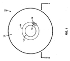
- the present invention is well suited for use with optical discs, such as an optical disc 10 illustrated in Figure 1 .
- the optical disc 10 comprises a centre hole 12, a non-information bearing centre annulus 14, and an information bearing annulus 16, as is well understood.
- the optical disc 10 may be a compact disc, a DVD, a mini disc, or the like, but is designed to store information or executable applications on the optical disc 10 for later recovery and usage by a data processing device such as a computer or audio/visual player.
- the optical disc 10 may further have a radio frequency identification (RFID) tag 18 positioned somewhere on the optical disc 10.
- RFID radio frequency identification
- the RFID tag 18 may be comparable to the MICROINSERT or ONETAG chips previously sold by the assignee of the present invention. These devices are embodiments of U.S. Patent Application Serial Numbers 09/61 8,505, filed 18 July 2000 and 09/678,271, filed 03 October 2000 . These RFID tags 18 are capable of interaction with Intermec's INTELLITAG interrogators, and have been expounded upon in several commonly owned applications, such as U.S. Patent Application Serial Numbers 1011 25,786 and 1011 25,783, both filed 18 April 2002 .
- the ONETAG and the MICROINSERT chips embody both an active and a passive sort of transponder, and both types are contemplated for use in the present invention.
- the RFID tag 18 may be operative at any number of frequencies, but specifically contemplated are bands centred around 125 kHz, 13.56 MHz, 915 MHz, and 2450 MHz.
- the RFID tag 18 is positioned on the non-information bearing centre annulus 14 and uses an antenna 19 associated with the optical disc 10 according to the teachings of U.S. Patent Application Serial Number 101131,576, filed 24 April 2002 .
- Other antennas 19 may also be used, such as a coil antenna for low frequencies, a dipole antenna, a patch antenna, an F antenna, or the like as needed or desired.
- the coupling to the antenna 19 may be through any appropriate means such as electric, electromagnetic, magnetic, electrostatic, or the like using appropriate elements such as capacitive or inductive reactive elements.
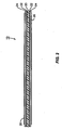
- the optical disc 10 is illustrated in cross-sectional form in Figure 2 , wherein it can be seen that the optical disc 10 begins with a central polycarbonate layer 20, covered with an aluminium layer 22 having data carrying pits (not illustrated) thereon.
- the aluminium layer 22 may be present on both sides of the polycarbonate layer 20.
- a voltage controlled optical modifier layer 24 Associated with the aluminium layer 22 is a voltage controlled optical modifier layer 24.
- the voltage controlled optical modifier layer 24 is operatively connected to an output voltage provided by the RFID tag 18.
- the voltage controlled optical modifier layer 24 may, in an exemplary embodiment, be a liquid crystal material that scatters or alters the polarization of illumination.
- An appropriate liquid crystal material comprises a twisted nematic type, which can make the disc either reflective, where the laser beam passes through the liquid crystal material and can read the bits in the aluminium layer 22, or non-reflective, where the layers form a cross polarized filter.
- materials could be used which change their refractive index such that they defocus an illuminating laser spot.
- Other materials could be a controllable mirrored surface behind the optical layer that could control readability.
- a piezoelectric layer such as the plastic film Polyvinyl Dienyl Fluoride, could be used that distorts the surface of the optical disc 10 such that an auto-focusing laser cannot track the changes in the surface fast enough.
- Another option is to include an electro-chromic material so that the monotone colour of the laser is selectively absorbed.
- An example of such an electro-chromic material is Lutetium di-phthalocyanine.
- the desired end result is that the disc is unreadable unless the RFID tag 18 has applied an output voltage to bias the voltage controlled optical modifier layer 24 properly.
- the RFID tag 18 only produces the proper output voltage when the RFID tag 18 has received the proper authorization from an interrogator 32 (see Figure 3 ).
- a covering layer 26 that protects the optical disc 10 from causal nicks, scratches and the like.
- Such covering layers are conventional in the industry of optical discs 10, and may be made from a polycarbonate material.
- an optical disc player 28 includes a laser head 30 that reads from and/or writes to the optical disc 10 as is well understood.
- the optical disc player 28 further may include an interrogator 32, such as an interrogator sold by INTERMEC or the like. It should be appreciated that while the interrogator 32 is shown inside the optical disc player 28, the interrogator 32 could be a hand held, portable, or stationary unit positioned outside the optical disc player 28.
- the optical disc player 28 may have a processor, such as a CPU 34 that controls the interrogator 32 and the laser head 30.
- the CPU 34 may further communicate to a remote location through a modem 36.
- the interrogator 32 may also have a modem 38 for communication to a remote location.
- the remote location may be connected to a network such as the Internet, the PSTN, or other communication network.
- the modems 36 and 38 may each be a wireless modem, an ISDN modem, a phone line modem, a cable modem, or the like as needed or desired.
- the modem 38 may be duplicative In the instance where the interrogator 32 is built into the optical disc reader 28, and is more likely to be present when the interrogator 32 is a distinct entity from the optical disc reader 28.
- Figure 3 may be further rearranged.
- a conventional personal computer with a DVD/CDRW drive and an interrogator associated therewith is particularly contemplated for use with the present invention.
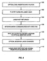
- FIG. 4 A general use of the present invention is illustrated in Figure 4 , with particularly contemplated embodiments being presented in Figures 5-9 .
- an optical disc 10 according to the present invention is placed into an optical disc player 28 (block 100).
- the optical disc player 28 turns on the laser head 30 (block 102).
- the voltage controlled optical modifier layer 24 is initially opaque or otherwise diffuses the laser from the laser head 30, and thus the laser is not returned to the laser head 30 for interpretation (block 104).
- the interrogator 32 is also turned on and communicates with the RFID tag 18 on the optical disc 10 (block 106). This interrogation may occur concurrently with the initial use of the laser, before the laser head 30 is turned on, or subsequently as needed or desired.
- the RFID tag 18 outputs a voltage to the voltage controlled optical modifier layer 24 (block 108).
- the voltage applied to the voltage controlled optical modifier layer 24 causes the characteristics of the voltage controlled optical modifier layer 24 to change (block 110) such that the pits in the aluminium layer 22 are now readable by the laser.
- the laser head 30 now gets a return signal from the laser bouncing off the pits in the aluminium layer 22 (block 112).
- the return signal is demodulated and interpreted as is conventional, and the optical disc player 28 provides the signal to an output device for playback or the like as needed or desired. Note that it is possible that the optical disc player 28 will always get a return signal at the laser head 30 if the interrogation signal is sent at the appropriate time.
- the voltage controlled optical modifier layer 24 may remain modified for a predetermined amount of time corresponding to a single playing of the contents of the optical disc 10, or other time frame as needed or desired.
- the RFID tag 18 may be associated with a capacitor (not shown) that the RFID tag 18 charges to a known threshold voltage.
- the threshold voltage is applied to the voltage controlled optical modifier layer 24 and kept in a condition that allows the optical disc 10 to be read.
- a resistor or other mechanism may be used to slowly discharge the capacitor over time.
- the rate of discharge is selected so that a predefined time elapses before the voltage controlled optical modifier layer 24 changes to a state in which the optical disc 10 Is not readable.
- the RFID tag 18 may store enough charge in a capacitor to drive a low energy dock device that counts cycles until a predetermined time period has elapsed, at which time the RFID tag 18 may discharge the capacitor or otherwise modify the behaviour of the voltage controlled optical modifier layer 24.
- the optical disc 10 included a photo-voltaic layer (as illustrated in Figure 10 )
- the use of the laser could remove charge from the layer.
- the layer would be discharged and the optical disc 10 would be unreadable.
- a filter could be used to inure that the laser, and not sunlight, discharged the photo-voltaic layer. Still other time delay discharge mechanisms could be used as needed or desired.
- the presence of a proper interrogation signal may cause the RFID tag 18 to instruct the voltage controlled optical modifier layer 24 to change permanently such that no further interrogation is required to use the optical disc 10.
- the embodiment disclosed in Figure 5 is appropriate for any situation where an optical disc 10 contains or will contain sensitive or confidential information. Such situations include personal information, financial information, and/or military or government information.
- the optical disc 10 is placed into an optical disc player 28 (block 150).
- the optical disc 10 is initially non-useable by the optical disc player 28. Specifically, the optical disc player 28 may not read the optical disc 10 nor write to the optical disc 10 (block 152).
- the user may then introduce an interrogation signal through an interrogator 32 (block 154).
- the interrogator 32 may be Integral with the optical disc player 28 or an external device, such as a battery powered key held near the optical disc player 28 and sending the interrogation signal through the walls of the optical disc player 28 to the RFID tag 18. With the presence of the interrogation signal, the RFID tag 18 outputs a voltage and changes the optical qualities of the voltage controlled optical modifier layer 24 (block 156).
- optical disc 10 is a write once, read only, or read-write disc, these abilities are enabled in the presence of the interrogation signal (block 158).
- a memory (not shown) may be used to track whether or not the disc has been written on. The memory may interface with the RFID tag 18 such that the optical disc 10 may not have another write command executed thereon.
- Figure 6 illustrates an embodiment wherein software is authenticated and paid for via a network, such as the Internet.
- the optical disc player 28 or the interrogator 32 may have a connection to a remote location, such as modems 36 and/or 38 or network connections.
- An optical disc 10 is inserted into the optical disc player 28 (block 200).
- the optical disc player 28 turns on the laser head 30 and fails to detect a return signal (block 202).
- the CPU 34 may detect this failed return signal and generate a command that a connection be made to a remote location over the network (block 204) so that an authorization to use the optical disc 10 may be secured.
- the address or contact information for the remote location may be located on a portion of the optical disc 10 that is not occluded by the voltage controlled optical modifier layer 24.
- the optical disc player 28 and/or interrogator 32 may connect automatically to a particular remote location.
- the remote location may query the CPU 34 or other device to determine what sort of command triggered the activation of the optical disc player 28. If the command was an installation command or a play command, the process may continue. If, however, the command was a copy command, the process may terminate.
- the remote location initiates a payment transaction (block 206).
- payment information may be secured from the individual trying to use the optical disc 10.
- Payment information may be secured through a credit card reader, manual entry through a keyboard, or other appropriate means as needed or desired. Payment may be made on a pay per use schedule, a pay per installation schedule, or other schedule as needed or desired.
- the remote location may send a signal to the interrogator 32 to generate an appropriate interrogation signal (block 208). This signal may be routed through the CPU 34 or directly to the interrogator 32 as needed or desired and depending on the existence of the modem 38.
- the interrogation signal is generated, and the RFID tag 18 receives the interrogation signal (block 210).
- the voltage controlled optical modifier layer 24 changes and the laser head 30 generates a return signal (block 212).
- the installation or playing of the contents of the optical disc 10 may proceed (block 214).
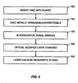
- the present invention may be used to authorize pay per view movies or other pay per play activities.
- This is illustrated in Figure 7 .
- the process Is very similar in that the optical disc 10 is inserted into the optical disc player 28 (block 250).
- the optical disc player 28 turns on the laser head 30 with a command to read the optical disc 10 and receives no return signal (block 252). Recognizing the absence of a return signal, the CPU 34 or other entity establishes a remote connection (block 254).
- the address or contact information for the remote location may be located on a portion of the optical disc 10 that is not occluded by the voltage controlled optical modifier layer 24.
- the optical disc player 28 and/or interrogator 32 may connect automatically to a particular remote location.
- a payment transaction may be initiated (block 256) to authorize a single playing of the content on the optical disc 10.
- the remote location may query the CPU 34 to see if the user is in fact trying to play the optical disc 10 or copy the optical disc 10. If the latter, the payment transaction may be cancelled or never initiated. In this manner, copying may be hindered.
- the remote location may authorize the interrogation signal (block 258).
- Payment information may be secured through a credit card reader, manual entry through a keyboard, or other appropriate means as needed or desired. Payment may be made on a pay per use schedule, a pay per installation schedule, or other schedule as needed or desired.
- the interrogator 32 generates the interrogation signal, which is received by the RFID tag 18 on the optical disc 10 (block 260).
- the RFID tag 18 outputs the needed voltage to change the properties of the voltage controlled optical modifier layer 24, and the laser may now generate a return signal that is received by the laser head 30 (block 262).
- the content on the optical disc 10 may then be played (block 264).
- a memory associated with the CPU 34, the interrogator 32, or the RFID tag 18 may track when it is appropriate for the voltage output by the RFID tag 18 to change such that the optical disc 10 is no longer readable, i.e., after one playing of the content.
- FIG. 8 Still another embodiment is Illustrated in Figure 8 , wherein a jukebox (not specifically illustrated) or similar playing device may contain a plurality of optical discs 10 with content thereon.
- Each of these optical discs 10 represents an investment, which if stolen would financially injure the jukebox operator.
- the jukebox Is analogous to the optical disc player 28, as the jukebox would contain an optical disc player 28 to function. To help prevent such theft, the present invention is useful.
- the optical discs 10 are placed in the jukebox (block 300).
- the jukebox may generate the desired interrogation signal throughout the jukebox (block 302).
- the interrogation signal may be limited to the area In and around the optical disc player 28 within the jukebox, In either event, the optical discs 10 play normally (block 304) while within the jukebox. At some point, an optical disc 10 may be removed from the jukebox, and thus removed from the presence of the interrogation signal (block 306). In the absence of the interrogation signal, the RFID tag 18 on the optical disc 10 does not generate the needed output voltage to change the optical qualities of the voltage controlled optical modifier layer 24, and thus the optical disc 10 no longer plays (block 308). While this does not prevent theft, it removes the incentive for the theft because the thief no longer has a usable optical disc 10, nor will anyone buy such a non-functioning optical disc 10.
- FIG. 9 Another embodiment is illustrated in Figure 9 .
- This embodiment is directed to helping reduce or prevent theft in a retail environment.
- This embodiment requires that the voltage controlled optical modifier layer 24 be stable at two different states.
- the first state causes the aluminium layer 22 to be illegible.
- the second state allows the aluminium layer 22 to be legible. More information on bi-stable materials may be found in the previously mentioned '834 British patent.
- Either state should be able to be maintained absent a signal from the RFID tag 18, but a signal from the RFID tag 18 may cause the voltage controlled optical modifier layer 24 to transition between these two states.
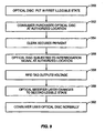
- the use of this two state voltage controlled optical modifier layer 24 begins when the optical disc 10 is put in the first illegible state (block 350). This may be done during manufacturing, arrival at a retail environment, or other time as needed or desired.
- a consumer purchases the optical disc 10 at an authorized location (block 352). This may entail picking the optical disc 10 off a rack in a store and approaching a cash register location or similar activity as is well understood.
- the clerk at the retail establishment secures payment for the optical disc 10 (block 354). Payment may be made through any conventional technique such as cash, check, credit card, debit card, or the like.
- the clerk then subjects the optical disc 10 to an interrogation signal generated proximate the authorized location (block 356).
- the interrogation signal may be generated by a portable, handheld interrogator 32, or the interrogator 32 may be integrated into a point of sale device such as a cash register or the like as needed or desired.
- the RFID tag 18 receives the interrogation signal and outputs a voltage to the voltage controlled optical modifier layer 24 (block 358).
- the voltage controlled optical modifier layer 24 changes to the second, legible state (block 360), and the consumer may use the optical disc 10 normally (block 362).
- the voltage controlled optical modifier layer 24 stays In the second legible state indefinitely.
- the present invention is not limited to simply changing the voltage controlled optical modifier layer 24 as described with respect to Figure 8 , but may also be combined with an electronic article surveillance (EAS) function, stock control, or logistics.
- EAS electronic article surveillance
- the RFID tag 18 operates at a centre frequency of 13.56 MHz
- a flag may also be set in the memory of the RFID tag 18. This flag may indicate that the optical disc 10 has been legitimately purchased. Still other flags may be set, or incorporated into the first flag. The other flags may indicate from whence the optical disc 10 was purchased as well as timestamp. Scanners at the store exit will sound an alarm if an RFID tag 18 with the Incorrect flag is detected.
- Such scanners and flag setting are common in the EAS art. This adds to the security and also helps prevent theft where a product is taken from the shelves and then taken directly to a refund station, with a claim that the receipt has been lost.
- the dual security measures may be a powerful deterrent to theft.
- Figure 9 may also be used in other non-retail establishments, such as a library for example, and need not be restricted to retail establishments. Further, while this embodiment does not prevent theft of the optical discs 10 per se, it does remove the incentive for the theft as the optical disc 10 Is worthless if the interrogation signal has not been applied to change the voltage controlled optical modifier layer 24 to its second, legible state.
- the concept may also be applied to optical memory cards, such as those used by the United States Department of Defense.
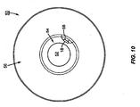
- Another option is the all-optical tag/disc 50 as illustrated in Figure 10 .
- Such an optical disc 50 is similar to an optical disc 10 in that it contains a centre hole 52, a non-information bearing annulus 54, and an information bearing annulus 56.
- An RFID tag 18 may be positioned on the optical disc 50 as previously described and connected to a voltage controlled optical modifier layer 24 as previously described. Further, the RFID tag 18 may be connected to a photo-voltaic area 58 of amorphous silicon or a polymeric semiconductor. Alternatively, the photo-voltaic area 58 may be a pyro-electric area.
- an optical disc writer To use the optical disc 50, an optical disc writer must first attempt to write a specified code to the photo-voltaic area 58, producing a voltage which powers up the RFID tag 18.
- the modulation of the laser provides a data input to the RFID tag 18, which, if correct, allows the RFID tag 18 to either clear the voltage controlled optical modifier layer 24 temporarily for reading, or by using the bi-state stable material discussed above, permanently enables the use of the optical disc 50.
- This technique may be used by itself or in conjunction with an interrogation signal as needed or desired for flexibility in assigning security protocols or the like.
- the RFID tag 18 may be interrogated and respond in a normal fashion until the interrogator 32 sends a predefined data sequence which causes the RFID tag 18 to accept commands. After receipt and acknowledgment of this predefined data sequence, the interrogator 32 may send a command to the RFID tag 18 to provide the desired output voltage that causes the change In the voltage controlled optical modifier layer 24.
Landscapes
- Engineering & Computer Science (AREA)
- Computer Security & Cryptography (AREA)
- Signal Processing (AREA)
- Business, Economics & Management (AREA)
- Physics & Mathematics (AREA)
- Accounting & Taxation (AREA)
- General Physics & Mathematics (AREA)
- Theoretical Computer Science (AREA)
- General Business, Economics & Management (AREA)
- Strategic Management (AREA)
- Finance (AREA)
- Nonlinear Science (AREA)
- Chemical & Material Sciences (AREA)
- Crystallography & Structural Chemistry (AREA)
- Optics & Photonics (AREA)
- Optical Recording Or Reproduction (AREA)
- Signal Processing For Digital Recording And Reproducing (AREA)
- Optical Record Carriers And Manufacture Thereof (AREA)
- Burglar Alarm Systems (AREA)
Abstract
Description
- The present invention relates to security devices for optical discs.
- Theft of intellectual property is a very prominent topic in the entertainment industries. Technologies to copy audio and video recordings have plagued the industry for many years. The advent of digital recordings has, in the eyes of the entertainment industries, exacerbated the problem. In the past, analogue copies got progressively worse such that eventually any copies made from the previous copy were worthless. Digital copies, each of which is just as pristine and precise as the previous copy, remove the previous limitation on repetitive copying.
- While the creation of illegal copies is troublesome to the entertainment industry, equally troubling is the theft of authorized copies of the works from retail outlets, jukeboxes, and the like. Shoplifting and similar theft account for extensive lost revenue for the entertainment industry. Optical discs, such as CDs and DVDs, because of their relatively small size, are easy targets for such theft and account for a substantial portion of those losses.
- Still other security concerns surround optical discs. Where the disc contains sensitive information, the loss and subsequent accessing of a disc may create problems for the person or entity whose information may be on the disc. Such information could be financial information, personal information, or confidential government information.
- In the state of the art, it is known to use read/write liquid crystals to write visual readable information onto an optical device for storing data. For example,
GB 2 354 834 AEP 0 612 037 A1 discloses a read/write optical device in form of a reprogrammable electronic responder card with visually readable information content. By changing the state of an optolaminate, readable information can be visually stored on the responder card. Nevertheless, the devices known in the state of the art have the drawback that a reading of stored information by an unauthorized third person can not be prohibited. - Thus, there remains a need for a device or technique that helps ensure that optical discs may not be read unless used in an authorized disc reader or cannot be used until after their use has been authorized.
- The present invention uses a specially created optical disc. The optical disc may comprise a base layer, an aluminium layer with data carrying pits, a voltage controlled optical modifier layer, a covering layer, and a radio frequency identification (RFID) tag. The RFID tag is associated with the voltage controlled optical modifier layer such that when the RFID tag is in the presence of an appropriate electromagnetic field, the RFID tag sends instructions to the voltage controlled optical modifier layer to control the ability of an optical reader to read data on the disc.
- The instructions to the voltage controlled optical modifier layer may be designed to render the optical modifier layer transparent such that the data carrying pits may be read, or may render the layer opaque such that the data carrying pits may not be read. Furthermore, the instructions and the optical modifier layer may be designed such that once the layer has been changed the layer remains that way. The RFID tag may be responsive to different protocols or commands such that the RFID tag causes the voltage controlled optical modifier layer to behave differently depending on the protocol or command received.
- In an exemplary embodiment, the voltage controlled optical modifier layer may be formed from a liquid crystal material or other material that changes its refractive index in the presence or absence of a voltage.
- The present invention has several uses, such as a security device for optical discs having sensitive information. The information may only be readable by an optical disc player that includes the appropriate type of RFID interrogator. The present invention may be used in a jukebox system such that the disc is rendered opaque unless used in an authorized jukebox. The present invention may be used as an electronic article surveillance (EAS) device in retail environments where unless the optical disc is interrogated at a cash register, the disc is unreadable. After interrogation during a sales transaction, the optical modifier layer may be instructed to become transparent such that the disc may be used normally. The present invention may also be used in pay per play activities, and software authentication and payment over a network schemes.
- An alternate embodiment may combine an all optical portion of an optical disc with the RFID tag for the same security purposes. If the all optical portion is not properly interrogated by a laser, the optical disc may be illegible.
- Those skilled In the art will appreciate the scope of the present Invention and realize additional aspects thereof after reading the following detailed description of the preferred embodiments in association with the accompanying drawing figures, and the appended claims.
- The accompanying drawing figures incorporated in and forming a part of this specification illustrate several aspects of the invention, and together with the description serve to explain the principles of the Invention.
-
Figure 1 illustrates an optical disc with an RFID tag disposed thereon; -
Figure 2 illustrates a cross-sectional view of the optical disc, taken along line 2-2 ofFigure 1 ; -
Figure 3 illustrates a simplified disc player with an RFID interrogator; -
Figure 4 illustrates a flow chart generally outlining an exemplary use of the present invention; -
Figure 5 illustrates a flow chart outlining use of the present invention with optical discs containing sensitive information; -
Figure 6 illustrates a flow chart outlining use of the present invention for software authentication and payment via a network; -
Figure 7 illustrates a flow chart outlining use of the present invention in a pay per play activity; -
Figure 8 illustrates a flow chart outlining use of the present invention in a jukebox activity; -
Figure 9 illustrates a flow chart outlining use of the present invention in a retail anti-theft activity; and -
Figure 10 illustrates an optical disc with an all optical portion for security purposes. - The embodiments set forth below represent the necessary information to enable those skilled in the art to practice the invention and illustrate the best mode of practicing the invention. Upon reading the following description in light of the accompanying drawing figures, those skilled in the art will understand the concepts of the invention and will recognize applications of these concepts not particularly addressed herein. It should be understood that these concepts and applications fall within the scope of the disclosure and the accompanying claims.
- The present invention is well suited for use with optical discs, such as an
optical disc 10 illustrated inFigure 1 . Theoptical disc 10 comprises acentre hole 12, a non-information bearingcentre annulus 14, and aninformation bearing annulus 16, as is well understood. Theoptical disc 10 may be a compact disc, a DVD, a mini disc, or the like, but is designed to store information or executable applications on theoptical disc 10 for later recovery and usage by a data processing device such as a computer or audio/visual player. Theoptical disc 10 may further have a radio frequency identification (RFID)tag 18 positioned somewhere on theoptical disc 10. - The
RFID tag 18 may be comparable to the MICROINSERT or ONETAG chips previously sold by the assignee of the present invention. These devices are embodiments ofU.S. Patent Application Serial Numbers 09/61 8,505, filed 18 July 2000 09/678,271, filed 03 October 2000 RFID tags 18 are capable of interaction with Intermec's INTELLITAG interrogators, and have been expounded upon in several commonly owned applications, such asU.S. Patent Application Serial Numbers 1011 25,786 and1011 25,783, both filed 18 April 2002 . The ONETAG and the MICROINSERT chips embody both an active and a passive sort of transponder, and both types are contemplated for use in the present invention. TheRFID tag 18 may be operative at any number of frequencies, but specifically contemplated are bands centred around 125 kHz, 13.56 MHz, 915 MHz, and 2450 MHz. - In an exemplary embodiment, the
RFID tag 18 is positioned on the non-information bearingcentre annulus 14 and uses anantenna 19 associated with theoptical disc 10 according to the teachings ofU.S. Patent Application Serial Number 101131,576, filed 24 April 2002 .Other antennas 19 may also be used, such as a coil antenna for low frequencies, a dipole antenna, a patch antenna, an F antenna, or the like as needed or desired. The coupling to theantenna 19 may be through any appropriate means such as electric, electromagnetic, magnetic, electrostatic, or the like using appropriate elements such as capacitive or inductive reactive elements. - The
optical disc 10 is illustrated in cross-sectional form inFigure 2 , wherein it can be seen that theoptical disc 10 begins with acentral polycarbonate layer 20, covered with analuminium layer 22 having data carrying pits (not illustrated) thereon. In the event that theoptical disc 10 is a double-sided DVD (illustrated), thealuminium layer 22 may be present on both sides of thepolycarbonate layer 20. Associated with thealuminium layer 22 is a voltage controlledoptical modifier layer 24. The voltage controlledoptical modifier layer 24 is operatively connected to an output voltage provided by theRFID tag 18. The voltage controlledoptical modifier layer 24 may, in an exemplary embodiment, be a liquid crystal material that scatters or alters the polarization of illumination. An appropriate liquid crystal material comprises a twisted nematic type, which can make the disc either reflective, where the laser beam passes through the liquid crystal material and can read the bits in thealuminium layer 22, or non-reflective, where the layers form a cross polarized filter. Alternatively, materials could be used which change their refractive index such that they defocus an illuminating laser spot. Other materials could be a controllable mirrored surface behind the optical layer that could control readability. As yet another option, a piezoelectric layer, such as the plastic film Polyvinyl Dienyl Fluoride, could be used that distorts the surface of theoptical disc 10 such that an auto-focusing laser cannot track the changes in the surface fast enough. Another option is to include an electro-chromic material so that the monotone colour of the laser is selectively absorbed. An example of such an electro-chromic material is Lutetium di-phthalocyanine. - While a plurality of materials could be used, the desired end result is that the disc is unreadable unless the
RFID tag 18 has applied an output voltage to bias the voltage controlledoptical modifier layer 24 properly. For more information on this topic, reference is made to Great Britain PatentGB 2,354,834 RFID tag 18 only produces the proper output voltage when theRFID tag 18 has received the proper authorization from an interrogator 32 (seeFigure 3 ). - Finally, capping the
optical disc 10 is acovering layer 26 that protects theoptical disc 10 from causal nicks, scratches and the like. Such covering layers are conventional in the industry ofoptical discs 10, and may be made from a polycarbonate material. - An example of the
optical disc 10 in use is illustrated inFigure 3 , wherein anoptical disc player 28 includes alaser head 30 that reads from and/or writes to theoptical disc 10 as is well understood. Theoptical disc player 28 further may include an interrogator 32, such as an interrogator sold by INTERMEC or the like. It should be appreciated that while the interrogator 32 is shown inside theoptical disc player 28, the interrogator 32 could be a hand held, portable, or stationary unit positioned outside theoptical disc player 28. - The
optical disc player 28 may have a processor, such as a CPU 34 that controls the interrogator 32 and thelaser head 30. The CPU 34 may further communicate to a remote location through amodem 36. Alternatively, or additionally, the interrogator 32 may also have amodem 38 for communication to a remote location. In both instances, the remote location may be connected to a network such as the Internet, the PSTN, or other communication network. Themodems modem 38 may be duplicative In the instance where the interrogator 32 is built into theoptical disc reader 28, and is more likely to be present when the interrogator 32 is a distinct entity from theoptical disc reader 28. - It should be appreciated that the components of
Figure 3 may be further rearranged. For example, a conventional personal computer with a DVD/CDRW drive and an interrogator associated therewith is particularly contemplated for use with the present invention. - A general use of the present invention is illustrated in
Figure 4 , with particularly contemplated embodiments being presented inFigures 5-9 . Initially, anoptical disc 10 according to the present invention is placed into an optical disc player 28 (block 100). Theoptical disc player 28 turns on the laser head 30 (block 102). The voltage controlledoptical modifier layer 24 is initially opaque or otherwise diffuses the laser from thelaser head 30, and thus the laser is not returned to thelaser head 30 for interpretation (block 104). - The interrogator 32 is also turned on and communicates with the
RFID tag 18 on the optical disc 10 (block 106). This interrogation may occur concurrently with the initial use of the laser, before thelaser head 30 is turned on, or subsequently as needed or desired. In response to the presence of an interrogation signal from the interrogator 32, theRFID tag 18 outputs a voltage to the voltage controlled optical modifier layer 24 (block 108). - The voltage applied to the voltage controlled
optical modifier layer 24 causes the characteristics of the voltage controlledoptical modifier layer 24 to change (block 110) such that the pits in thealuminium layer 22 are now readable by the laser. Thelaser head 30 now gets a return signal from the laser bouncing off the pits in the aluminium layer 22 (block 112). The return signal is demodulated and interpreted as is conventional, and theoptical disc player 28 provides the signal to an output device for playback or the like as needed or desired. Note that it is possible that theoptical disc player 28 will always get a return signal at thelaser head 30 if the interrogation signal is sent at the appropriate time. - Vacations on this process include requiring a continuous interrogation signal from the interrogator 32 such that if the interrogation signal is ever absent, the
optical disc 10 becomes unreadable again. - Alternatively, the voltage controlled
optical modifier layer 24 may remain modified for a predetermined amount of time corresponding to a single playing of the contents of theoptical disc 10, or other time frame as needed or desired. In an exemplary embodiment of this concept, theRFID tag 18 may be associated with a capacitor (not shown) that theRFID tag 18 charges to a known threshold voltage. The threshold voltage is applied to the voltage controlledoptical modifier layer 24 and kept in a condition that allows theoptical disc 10 to be read. A resistor or other mechanism may be used to slowly discharge the capacitor over time. In a preferred embodiment, the rate of discharge is selected so that a predefined time elapses before the voltage controlledoptical modifier layer 24 changes to a state in which theoptical disc 10 Is not readable. As another option, theRFID tag 18 may store enough charge in a capacitor to drive a low energy dock device that counts cycles until a predetermined time period has elapsed, at which time theRFID tag 18 may discharge the capacitor or otherwise modify the behaviour of the voltage controlledoptical modifier layer 24. As yet another option, if theoptical disc 10 included a photo-voltaic layer (as illustrated inFigure 10 ), the use of the laser could remove charge from the layer. Thus, after a number of usages of theoptical disc 10, the layer would be discharged and theoptical disc 10 would be unreadable. A filter could be used to inure that the laser, and not sunlight, discharged the photo-voltaic layer. Still other time delay discharge mechanisms could be used as needed or desired. - As yet another option, the presence of a proper interrogation signal may cause the
RFID tag 18 to instruct the voltage controlledoptical modifier layer 24 to change permanently such that no further interrogation is required to use theoptical disc 10. These concepts will be explored in greater detail below with respect toFigures 5-9 . - The embodiment disclosed in
Figure 5 is appropriate for any situation where anoptical disc 10 contains or will contain sensitive or confidential information. Such situations include personal information, financial information, and/or military or government information. Initially, theoptical disc 10 is placed into an optical disc player 28 (block 150). Theoptical disc 10 is initially non-useable by theoptical disc player 28. Specifically, theoptical disc player 28 may not read theoptical disc 10 nor write to the optical disc 10 (block 152). The user may then introduce an interrogation signal through an interrogator 32 (block 154). The interrogator 32 may be Integral with theoptical disc player 28 or an external device, such as a battery powered key held near theoptical disc player 28 and sending the interrogation signal through the walls of theoptical disc player 28 to theRFID tag 18. With the presence of the interrogation signal, theRFID tag 18 outputs a voltage and changes the optical qualities of the voltage controlled optical modifier layer 24 (block 156). - If the
optical disc 10 is a write once, read only, or read-write disc, these abilities are enabled in the presence of the interrogation signal (block 158). In the event that theoptical disc 10 Is a write once disc, a memory (not shown) may be used to track whether or not the disc has been written on. The memory may interface with theRFID tag 18 such that theoptical disc 10 may not have another write command executed thereon. -
Figure 6 illustrates an embodiment wherein software is authenticated and paid for via a network, such as the Internet. In this embodiment, theoptical disc player 28 or the interrogator 32 may have a connection to a remote location, such asmodems 36 and/or 38 or network connections. Anoptical disc 10 is inserted into the optical disc player 28 (block 200). Theoptical disc player 28 turns on thelaser head 30 and fails to detect a return signal (block 202). The CPU 34 may detect this failed return signal and generate a command that a connection be made to a remote location over the network (block 204) so that an authorization to use theoptical disc 10 may be secured. The address or contact information for the remote location may be located on a portion of theoptical disc 10 that is not occluded by the voltage controlledoptical modifier layer 24. Alternatively, theoptical disc player 28 and/or interrogator 32 may connect automatically to a particular remote location. The remote location may query the CPU 34 or other device to determine what sort of command triggered the activation of theoptical disc player 28. If the command was an installation command or a play command, the process may continue. If, however, the command was a copy command, the process may terminate. - The remote location initiates a payment transaction (block 206). Thus, payment information may be secured from the individual trying to use the
optical disc 10. Payment information may be secured through a credit card reader, manual entry through a keyboard, or other appropriate means as needed or desired. Payment may be made on a pay per use schedule, a pay per installation schedule, or other schedule as needed or desired. Upon satisfaction that payment has been secured, the remote location may send a signal to the interrogator 32 to generate an appropriate interrogation signal (block 208). This signal may be routed through the CPU 34 or directly to the interrogator 32 as needed or desired and depending on the existence of themodem 38. The interrogation signal is generated, and theRFID tag 18 receives the interrogation signal (block 210). The voltage controlledoptical modifier layer 24 changes and thelaser head 30 generates a return signal (block 212). The installation or playing of the contents of theoptical disc 10 may proceed (block 214). - In a similar vein, the present invention may be used to authorize pay per view movies or other pay per play activities. This is illustrated in
Figure 7 . The process Is very similar in that theoptical disc 10 is inserted into the optical disc player 28 (block 250). Theoptical disc player 28 turns on thelaser head 30 with a command to read theoptical disc 10 and receives no return signal (block 252). Recognizing the absence of a return signal, the CPU 34 or other entity establishes a remote connection (block 254). The address or contact information for the remote location may be located on a portion of theoptical disc 10 that is not occluded by the voltage controlledoptical modifier layer 24. Alternatively, theoptical disc player 28 and/or interrogator 32 may connect automatically to a particular remote location. - Once in communication with the remote location, a payment transaction may be initiated (block 256) to authorize a single playing of the content on the
optical disc 10. The remote location may query the CPU 34 to see if the user is in fact trying to play theoptical disc 10 or copy theoptical disc 10. If the latter, the payment transaction may be cancelled or never initiated. In this manner, copying may be hindered. - Once payment Is secured, the remote location may authorize the interrogation signal (block 258). Payment information may be secured through a credit card reader, manual entry through a keyboard, or other appropriate means as needed or desired. Payment may be made on a pay per use schedule, a pay per installation schedule, or other schedule as needed or desired. The interrogator 32 generates the interrogation signal, which is received by the
RFID tag 18 on the optical disc 10 (block 260). TheRFID tag 18 outputs the needed voltage to change the properties of the voltage controlledoptical modifier layer 24, and the laser may now generate a return signal that is received by the laser head 30 (block 262). The content on theoptical disc 10 may then be played (block 264). A memory associated with the CPU 34, the interrogator 32, or theRFID tag 18 may track when it is appropriate for the voltage output by theRFID tag 18 to change such that theoptical disc 10 is no longer readable, i.e., after one playing of the content. - Still another embodiment is Illustrated in
Figure 8 , wherein a jukebox (not specifically illustrated) or similar playing device may contain a plurality ofoptical discs 10 with content thereon. Each of theseoptical discs 10 represents an investment, which if stolen would financially injure the jukebox operator. For the purposes of this embodiment, the jukebox Is analogous to theoptical disc player 28, as the jukebox would contain anoptical disc player 28 to function. To help prevent such theft, the present invention is useful. Theoptical discs 10 are placed in the jukebox (block 300). The jukebox may generate the desired interrogation signal throughout the jukebox (block 302). Alternatively, the interrogation signal may be limited to the area In and around theoptical disc player 28 within the jukebox, In either event, theoptical discs 10 play normally (block 304) while within the jukebox. At some point, anoptical disc 10 may be removed from the jukebox, and thus removed from the presence of the interrogation signal (block 306). In the absence of the interrogation signal, theRFID tag 18 on theoptical disc 10 does not generate the needed output voltage to change the optical qualities of the voltage controlledoptical modifier layer 24, and thus theoptical disc 10 no longer plays (block 308). While this does not prevent theft, it removes the incentive for the theft because the thief no longer has a usableoptical disc 10, nor will anyone buy such a non-functioningoptical disc 10. - Another embodiment is illustrated in
Figure 9 . This embodiment is directed to helping reduce or prevent theft in a retail environment. This embodiment requires that the voltage controlledoptical modifier layer 24 be stable at two different states. The first state causes thealuminium layer 22 to be illegible. The second state allows thealuminium layer 22 to be legible. More information on bi-stable materials may be found in the previously mentioned '834 British patent. Either state should be able to be maintained absent a signal from theRFID tag 18, but a signal from theRFID tag 18 may cause the voltage controlledoptical modifier layer 24 to transition between these two states. The use of this two state voltage controlledoptical modifier layer 24 begins when theoptical disc 10 is put in the first illegible state (block 350). This may be done during manufacturing, arrival at a retail environment, or other time as needed or desired. - A consumer purchases the
optical disc 10 at an authorized location (block 352). This may entail picking theoptical disc 10 off a rack in a store and approaching a cash register location or similar activity as is well understood. The clerk at the retail establishment secures payment for the optical disc 10 (block 354). Payment may be made through any conventional technique such as cash, check, credit card, debit card, or the like. The clerk then subjects theoptical disc 10 to an interrogation signal generated proximate the authorized location (block 356). The interrogation signal may be generated by a portable, handheld interrogator 32, or the interrogator 32 may be integrated into a point of sale device such as a cash register or the like as needed or desired. - The
RFID tag 18 receives the interrogation signal and outputs a voltage to the voltage controlled optical modifier layer 24 (block 358). The voltage controlledoptical modifier layer 24 changes to the second, legible state (block 360), and the consumer may use theoptical disc 10 normally (block 362). The voltage controlledoptical modifier layer 24 stays In the second legible state indefinitely. - The present invention is not limited to simply changing the voltage controlled
optical modifier layer 24 as described with respect toFigure 8 , but may also be combined with an electronic article surveillance (EAS) function, stock control, or logistics. If, for example, theRFID tag 18 operates at a centre frequency of 13.56 MHz, when the interrogation signal is sent to theRFID tag 18 inblock 356 to make the disc legible, a flag may also be set in the memory of theRFID tag 18. This flag may indicate that theoptical disc 10 has been legitimately purchased. Still other flags may be set, or incorporated into the first flag. The other flags may indicate from whence theoptical disc 10 was purchased as well as timestamp. Scanners at the store exit will sound an alarm if anRFID tag 18 with the Incorrect flag is detected. Such scanners and flag setting are common in the EAS art. This adds to the security and also helps prevent theft where a product is taken from the shelves and then taken directly to a refund station, with a claim that the receipt has been lost. The dual security measures may be a powerful deterrent to theft. - Note that the embodiment of
Figure 9 may also be used in other non-retail establishments, such as a library for example, and need not be restricted to retail establishments. Further, while this embodiment does not prevent theft of theoptical discs 10 per se, it does remove the incentive for the theft as theoptical disc 10 Is worthless if the interrogation signal has not been applied to change the voltage controlledoptical modifier layer 24 to its second, legible state. - Numerous variations to the concept are possible. For example, the concept may also be applied to optical memory cards, such as those used by the United States Department of Defence. Another option is the all-optical tag/
disc 50 as illustrated inFigure 10 . Such anoptical disc 50 is similar to anoptical disc 10 in that it contains acentre hole 52, anon-information bearing annulus 54, and aninformation bearing annulus 56. AnRFID tag 18 may be positioned on theoptical disc 50 as previously described and connected to a voltage controlledoptical modifier layer 24 as previously described. Further, theRFID tag 18 may be connected to a photo-voltaic area 58 of amorphous silicon or a polymeric semiconductor. Alternatively, the photo-voltaic area 58 may be a pyro-electric area. To use theoptical disc 50, an optical disc writer must first attempt to write a specified code to the photo-voltaic area 58, producing a voltage which powers up theRFID tag 18. The modulation of the laser provides a data input to theRFID tag 18, which, if correct, allows theRFID tag 18 to either clear the voltage controlledoptical modifier layer 24 temporarily for reading, or by using the bi-state stable material discussed above, permanently enables the use of theoptical disc 50. This technique may be used by itself or in conjunction with an interrogation signal as needed or desired for flexibility in assigning security protocols or the like. - Note further that while in general the presence or absence of an interrogation signal has been used to trigger the
RFID tag 18 to send the voltage signal to the voltage controlledoptical modifier layer 24, it is also possible that theRFID tag 18 may be interrogated and respond in a normal fashion until the interrogator 32 sends a predefined data sequence which causes theRFID tag 18 to accept commands. After receipt and acknowledgment of this predefined data sequence, the interrogator 32 may send a command to theRFID tag 18 to provide the desired output voltage that causes the change In the voltage controlledoptical modifier layer 24. - Note that while the present discussion has been phrased in terms of disabling an entire
optical disc 10, it is possible that only a portion of theoptical disc 10 may be disabled to achieve the same results. For example, disabling the country code and index information on a DVD may make the DVD unreadable and achieve the same results. - Those skilled in the art will recognize improvements and modifications to the preferred embodiments of the present invention. All such improvements and modifications are considered within the scope of the concepts disclosed herein and the claims that follow.
Claims (65)
- An optical device (10,50) comprising:in a first case a content bearing medium having an edge; a photo-voltaic area (58) proximate the edge, a content lager (22), and a voltage controlled optical modifier layer (24), orin a second case in which the optical device is an optical disc (10, 50), a content layer (22) adapted to have content encoded thereon; and a voltage controlled optical modifier layer (24),characterized in that
the voltage controlled optical modifier layer (24) is associated with the content layer (22) and in that
the optical device (10, 50) further comprises
in the first case a RFID tag (18) connected to the photo-voltaic area (58) such that after an optical disc writer (28) attempts to write a predefined interrogation signal on the photo-voltaic area (58), the RFID tag (18) produces an output voltage that causes the voltage controlled optical modifier layer (24) to allow the content layer (22) to be accessed or
in the second case an RFID tag (18) having a voltage output, said RFID tag (18) responsive to an interrogation signal such that said voltage output changes based on the presence or absence of the said signal, wherein the voltage controlled optical modifier layer (24) is operatively connected with said RFID tag (18) such that said voltage controlled optical modifier layer may prevent at least a portion of said content layer (22) from being read by an optical disc player (28) unless said signal has been applied to said RFID tag (18) and said KFID tag (18) has provided an appropriate voltage signal at the voltage output to the voltage controlled optical modifier layer (24). - The optical disc of claim 1, wherein said content bearing medium optical comprises an optical memory card.
- The optical disc of claim 1, wherein said voltage controlled optical layer (24) comprises a material selected from the group consisting of: a liquid crystal material; a piezoelectric material, and a controllable mirrored surface.
- The optical disc of claim 1, wherein said RFID tag (18) is responsive to a predefined data sequence before changing the output voltage.
- The optical disc of claim 1, wherein said voltage controlled optical modifier layer (24) comprises a material that is stable in two states, one state in which the content layer (22) is legible and one state in which the content layer (22) is illegible.
- The optical disc of claim 1, wherein said optical disc (10) comprises a disc selected from the group consisting of: a DVD, an audio CD, a software CD, a CDRW, and a CD write once.
- The optical disc of claim 1, wherein said RFID tag (18) is responsive on a frequency band around a centre frequency selected from the group consisting of: 125 kHz, 13.56 MHz, 915 MHz, and 2450 MHz.
- The optical disc of claim 1, wherein upon receipt of the appropriate interrogation signal, the RFID tag (18) outputs a voltage which causes said voltage controlled optical modifier layer (24) to change to a second state indefinitely such that said content layer (22) is legible.
- The optical disc of claim 1, wherein said content layer (22) comprises content providing data for connecting to a remote location that is accessible independently of whether an appropriate signal is present.
- The optical disc of claim 1, wherein said voltage controlled optical modifier layer (24) causes said content layer (22) to be legible for a predetermined amount of time after exposure to the appropriate interrogation signal.
- The optical disc of claim 1, wherein said RPID tag (18) is responsive to an interrogation signal generated by an interrogator (32).
- A method of controlling content on an optical disc (10, 50), comprising:storing content on an optical disc (10, 50), characterized in thatthe method comprises the provision of a content layer (22) comprised by the optical disc (10, 50) and the provision of a voltage controlled optical modifier layer (24) associated with said content layer, and in that the method further comprises precluding reading at least a portion of content from the content layer (22) in the absence of a predefined signal to an RFID tag (18) associated with the optical modifier layer (24).
- The method of claim 12 is characterized in that the content is software.
- The method of claim 12 or 13, further comprising generating said predefined signal proximate the optical disc (10, 50).
- The method of claim 14, further comprising contacting a remote location prior to generating said predefined signal.
- The method of claim 15, wherein contacting a remote location comprises contacting a remote location over a network (36, 38).
- The method of claim 15, wherein contacting a remote location further comprises initiating a payment transaction prior to generating said predefined signal.
- The method of claim 12 or 13, wherein precluding reading content from the content layer (22) in the absence of a predefined signal to an RFID tag (18) associated with the optical modifier layer (24) comprises preventing an optical disc reader (28) from accessing the content by hindering the optical disc leader (28) from securing a return signal from a surface of the optical disc (10, 50).
- The method of claim 18, wherein hindering the optical disc reader (28) from securing a return signal from a surface of the optical disc (10, 50) comprises using a material selected from the group consisting of: a liquid crystal material, a controllable mirrored material, and a piezoelectric material.
- The method of claim 18, further comprising, upon receipt of said predefined signal, generating an output voltage with the RFID tag (18).
- The method of claim 20, further comprising using said output voltage of the RFID tag disc (18) to change a quality of the voltage controlled optical modifier layer (24) on the optical disc (10, 50) such that the disc (10, 50) is readable by an optical disc reader (28).
- The method of claim 12 or 13, wherein storing content on the optical disc (10, 50) comprises storing video content on a DVD (10, 50).
- The method of claim 12 or 13, wherein precluding reading content from the content layer (22) in the absence of a predefined interrogation signal to an RFID tag (18) associated with the optical modifier layer (24) comprises selectively allowing pay per view access to the content after securing permission from a remote location.
- A method of protecting information on an optical disc (10, 50) according to claim 12, further comprising: associating the optical disc (10, 50) with an RFID tag (18) and a voltage controlled optical modifier layer (24); and
controlling said optical modifier layer (24) with said RFID tag (18) such that at least a portion of a content layer (22) on the optical disc (10, 50) is inaccessible in the absence of a predefined signal. - The method of claim 24, wherein controlling said optical modifier layer (24) comprises changing a refractive index of said optical modifier layer (24) with an output voltage of said RFID tag (18) such that a laser cannot read from or write to said content layer (22).
- The method of claim 24, wherein controlling said optical modifier layer (24) comprises controlling a material selected from the group consisting of: a liquid crystal material, a piezoelectric material, and a controllable mirrored material.
- The method of claim 24, further comprising interrogating the optical disc (10, 50) with said predefined signal.
- The method of claim 27, wherein interrogating the optical disc (10, 50) comprises interrogating the optical disc (10, 50) with an interrogator (32) integrated into an optical disc player (28).
- The method of claim 27, wherein interrogating the optical disc comprises interrogating the optical disc (10, 50) with an interrogator distinct from an optical disc player (28).
- The method of claim 27, further comprising securing permission to generate the predefined signal from a remote location.
- The method of claim 24, further comprising allowing access to the content layer (22) of the optical disc (10, 50) for a predetermined amount of time after exposure to the predefined signal.
- A method of controlling use of an optical disc (10, 50), comprising the steps of the method according to claim 24, wherein associating the disc (10, 50) with an RFID tag (18) comprises: installing an RFID tag (18) on the optical disc (10, 50); and wherein controlling said optical modifier layer (24) comprises interrogating the optical disc (10, 50) with a predefined signal; generating an output voltage from said RFID tag (18); and directing said output voltage to the voltage controlled optical modifier layer (24) such that the optical characteristics of said optical modifier layer (24) change to allow content to be read from a content layer (22).
- The method of claim 32, wherein interrogating the optical disc (10, 50) comprises interrogating the optical disc (10, 50) with an interrogator (32) integrated into an optical disc player
- The method of claim 32, wherein interrogating the optical disc (10, 50) comprises interrogating the optical disc (10, 50) with an interrogator that operates as a unit independent of an optical disc player (28).
- The method of claim 32, further comprising contacting a remote location to secure permission to send the predefined interrogation signal.
- The method of claim 35, wherein contacting a remote location comprises contacting a remote location with an interrogator (32).
- The method of claim 35, wherein contacting a remote location comprises contacting a remote location with an optical disc player (28).
- The method of claim 32, further comprising reading the optical disc (10, 50) with an optical disc player (28).
- The method of claim 32, further comprising writing to the optical disc (10, 50) with an optical disc player (28).
- The method of claim 32, further comprising installing software from the optical disc (10, 50).
- The method of claim 32, further comprising installing the optical disc (10, 50) in a juke-box.
- The method of claim 32, further comprising storing sensitive information on the optical disc (10, 50) and precluding access thereto except in the presence of the predefined signal.
- The method of claim 32, further comprising allowing access to audio content on the optical disc (10, 50) in the presence of the predefined signal.
- The method of claim 43, further comprising denying access to the audio content on the optical disc (10, 50) in the absence of the predefined signal.
- The method of claim 32, further comprising allowing access to video content on the optical disc (10, 50) in the presence of the predefined signal.
- The method of claim 45, further comprising denying access to the video content on the optical disc (10, 50) in the absence of the predefined signal.
- The method of claim 32, wherein directing said output voltage to a voltage controlled optical modifier layer (24) such that the optical characteristics of the optical modifier layer (24) change to allow content to be read from a content layer (22) comprises changing a state of a dual state optical modifier layer (24) from a first state to a second state and wherein said optical modifier layer (24) remains in said second state indefinitely.
- The method of claim 32, wherein directing said output voltage to a voltage controlled optical modifier layer (24) such that the optical characteristics of the optical modifier layer (24) change to allow content to be read from a content layer (22) comprises changing a refractive index of a liquid crystal material.
- The method of claim 32, wherein directing said output voltage to a voltage controlled optical modifier layer (24) such that the optical characteristics of the optical modifier layer (24) change to allow content to be read from a content layer (22) comprises changing the reflective qualities of a mirrored surface.
- The method of claim 32, wherein directing said output voltage to a voltage controlled optical modifier layer (24) such that the optical characteristics of the optical modifier layer (24) change to allow content to be read from a content layer (22) comprises changing a shape of a piezoelectric material.
- The method of claim 32, wherein interrogating the optical disc (10, 50) with a predefined signal comprises interrogating the optical disc (10, 50) in a retail environment during a payment transaction.
- The method of claim 32, wherein interrogating the optical disc (10, 50) with a predefined signal comprises interrogating the optical disc (10, 50) with a predefined interrogation signal after securing payment from a consumer desiring to purchase access to content on the optical disc (10, 50).
- A method of inhibiting theft at a jukebox, comprising the steps of the method according to claim 24, wherein the method further comprises:installing said optical disc (10, 50) in a jukebox; and interrogating said RFID tag (18) with a predefined signal such that saidRFID tag (18) causes the optical modifier layer (24) to make said optical disc (10, 50) legible to an optical disc reader (28) associated with the jukebox.
- The method of claim 53, wherein associating an optical disc (10, 50) with an RFID tag (18) that controls an optical modifier layer (24) on said optical disc (10, 50) comprises associating an RFID tag (18) that operates at a frequency centred around the frequencies selected from the group consisting of: 125 kHz, 13.56 MHz, 915 MHz, and 2450 MHz.
- The method of claim 53, further comprising causing said optical modifier layer (24) to make said optical disc (10, 50) illegible to an optical disc reader (28)in the absence of said predefined signal.
- The method of claim 55, wherein causing said optical modifier layer (24) to make said optical disc (10, 50) illegible to an optical disc reader (28)in the absence of said predefined signal comprises causing an optical modifier layer (24) selected from a material in the group consisting of: a piezoelectric layer, a liquid crystal layer, and a controllable mirrored layer to make the optical disc (10, 50) illegible.
- The method of claim 53, wherein associating an optical disc (10, 50) with an RFID tag (18) that controls an optical modifier layer (24) on said optical disc (10, 50) comprises controlling said optical modifier layer (24) with an output voltage from said RFID tag (18).
- A method of inhibiting theft in a retail establishment, comprising the steps of the method according to claim 24 wherein controlling said optical modifier layer (24) comprises: causing the optical modifier layer (24) to exist in a first state that renders at least a portion of the optical disc (10, 50) illegible to an optical disc render (28); and selectively modifying the optical modifier layer (24) to a second state in which the optical disc (10, 50) is legible to an optical disc reader (28) after a consumer has paid for the optical disc (10, 50).
- The method of claim 58, wherein said selectively modifying comprises sending a signal to the RFID tag (18) on the optical disc (10, 50).
- The method of claim 59, wherein sending a signal to the RFID tag (18) on the optical disc (10, 50) comprises sending an interrogation signal from an interrogator integrated into a point of sale device.
- The method of claim 59, wherein sending a signal to the RFID tag (18) on the optical disc (10, 50) comprises sending an interrogation signal from a portable interrogator (32) associated with a sales clerk responsible for handling collection of payment for the optical disc (10, 50).
- The method of claim 58, wherein sending a signal comprises sending an interrogation signal at a frequency centred around the frequencies selected from the group consisting of: 125 kHz, 13.56 MHz, 915 MHz, and 2450 MHz.
- The method of claim 58, further comprising setting a flag in memory associated with the RFID tag (18).
- The method of claim 63, wherein setting a flag in memory associated with the RFID tag (18) comprises indicating that the optical disc (10, 50) was legitimately purchased.
- The method of claim 64, further comprising storing in memory an indication of from whence the optical disc (10, 50) was legitimately purchased and a timestamp.
Applications Claiming Priority (3)
| Application Number | Priority Date | Filing Date | Title |
|---|---|---|---|
| US241924 | 2002-09-12 | ||
| US10/241,924 US7275040B2 (en) | 2002-09-12 | 2002-09-12 | RFID security device for optical disc |
| PCT/IB2003/004346 WO2004025645A2 (en) | 2002-09-12 | 2003-09-10 | Rfid security device for optical disc |
Publications (2)
| Publication Number | Publication Date |
|---|---|
| EP1540411A2 EP1540411A2 (en) | 2005-06-15 |
| EP1540411B1 true EP1540411B1 (en) | 2008-06-11 |
Family
ID=31991288
Family Applications (1)
| Application Number | Title | Priority Date | Filing Date |
|---|---|---|---|
| EP03748409A Expired - Lifetime EP1540411B1 (en) | 2002-09-12 | 2003-09-10 | Rfid security device for optical disc |
Country Status (9)
| Country | Link |
|---|---|
| US (5) | US7275040B2 (en) |
| EP (1) | EP1540411B1 (en) |
| JP (2) | JP4262679B2 (en) |
| KR (1) | KR100734681B1 (en) |
| CN (1) | CN100582873C (en) |
| AT (1) | ATE398297T1 (en) |
| AU (1) | AU2003267714A1 (en) |
| DE (1) | DE60321578D1 (en) |
| WO (1) | WO2004025645A2 (en) |
Families Citing this family (94)
| Publication number | Priority date | Publication date | Assignee | Title |
|---|---|---|---|---|
| US6606247B2 (en) * | 2001-05-31 | 2003-08-12 | Alien Technology Corporation | Multi-feature-size electronic structures |
| CA2485108A1 (en) * | 2002-05-09 | 2003-11-20 | Kestrel Wireless, Inc. | Method and system for enabling electronic transactions via a personal device |
| US7227445B2 (en) * | 2002-07-31 | 2007-06-05 | Kestrel Wireless, Inc. | Wireless activation system and method |
| US7275040B2 (en) * | 2002-09-12 | 2007-09-25 | Mineral Lassen Llc | RFID security device for optical disc |
| US7253735B2 (en) | 2003-03-24 | 2007-08-07 | Alien Technology Corporation | RFID tags and processes for producing RFID tags |
| US20050015970A1 (en) * | 2003-06-12 | 2005-01-27 | Matrics, Inc. | Method, system, and apparatus for transfer of dies using a pin plate |
| JP2007526590A (en) * | 2003-06-23 | 2007-09-13 | ケストレル ワイヤレス,インク. | Optical media operating method and apparatus |
| EP1598815B1 (en) * | 2004-05-17 | 2008-11-19 | Sony DADC Austria AG | Optical data carrier, method for producing an optical data carrier and a device for producing an optical data carrier |
| US20060281523A1 (en) * | 2004-06-23 | 2006-12-14 | Walker Jay S | Video content determinative keno game system and method |
| US7850518B2 (en) * | 2004-06-23 | 2010-12-14 | Walker Digital, Llc | Video content determinative Keno game system and method |
| US20050288096A1 (en) * | 2004-06-23 | 2005-12-29 | Walker Digital, Llc | Methods and apparatus for facilitating a payout at a gaming device using audio / video content |
| US8597101B2 (en) | 2004-06-23 | 2013-12-03 | Igt | Video content determinative keno game system and method |
| US20060015752A1 (en) * | 2004-07-16 | 2006-01-19 | Promega Corporation | Memory having RFID tag, decryption technique for use with the memory, and memory reader or writer for use with the memory |
| FR2873847B1 (en) * | 2004-07-30 | 2007-01-26 | Arjowiggins Security Soc Par A | OPTICAL DEVICE HAVING AN IDENTIFICATION ELEMENT |
| US20090052309A1 (en) * | 2004-08-27 | 2009-02-26 | Ip And Innovation Company Holdings (Pty) Limited | Optical disc comprising rf transponder |
| CN101010677A (en) * | 2004-09-06 | 2007-08-01 | 皇家飞利浦电子股份有限公司 | Portable storage device and method for exchanging data |
| US8035482B2 (en) * | 2004-09-07 | 2011-10-11 | Eastman Kodak Company | System for updating a content bearing medium |
| US7292147B2 (en) * | 2004-09-24 | 2007-11-06 | Microsoft Corporation | Optical disk and method of integrating a high gain RFID antenna |
| US7378971B2 (en) * | 2004-10-01 | 2008-05-27 | Hitachi America, Ltd. | Radio frequency identification tags for digital storage discs |
| US20060095385A1 (en) * | 2004-10-26 | 2006-05-04 | Paul Atkinson | Method and network for selectively controlling the utility a target |
| US7452748B1 (en) | 2004-11-08 | 2008-11-18 | Alien Technology Corporation | Strap assembly comprising functional block deposited therein and method of making same |
| US7688206B2 (en) | 2004-11-22 | 2010-03-30 | Alien Technology Corporation | Radio frequency identification (RFID) tag for an item having a conductive layer included or attached |
| US7385284B2 (en) * | 2004-11-22 | 2008-06-10 | Alien Technology Corporation | Transponder incorporated into an electronic device |
| US20060132285A1 (en) * | 2004-12-07 | 2006-06-22 | Paul Atkinson | Device and method for selectively controlling a processing device |
| US20060277411A1 (en) * | 2004-12-07 | 2006-12-07 | Reynolds Christopher H | Security and storage system and method |
| US20060192653A1 (en) * | 2005-02-18 | 2006-08-31 | Paul Atkinson | Device and method for selectively controlling the utility of an integrated circuit device |
| US7869338B2 (en) * | 2005-02-24 | 2011-01-11 | Panasonic Corporation | Position detection device, position detection method, position detection control device, position detection control method, position detection control program, access authentication device, access authentication method, access authentication control device, access authentication control method, access authentication control program, information storage device, and optical disk |
| AU2006220971A1 (en) * | 2005-03-03 | 2006-09-14 | Enxnet, Inc. | Optical disc having a reduced planar thickness |
| US7417713B2 (en) * | 2005-04-06 | 2008-08-26 | Warner Bros. Entertainment Inc. | Optical disc with a theft deterrent coating |
| CA2604437A1 (en) * | 2005-04-18 | 2006-10-26 | Veriloc, Llc | Piracy-protected recording media |
| US7280043B2 (en) * | 2005-05-09 | 2007-10-09 | Industrial Technology Research Institute | Apparatus for impeding counterfeiting, impeding stealing and managing optical disk stock |
| JP2008541289A (en) * | 2005-05-20 | 2008-11-20 | エヌエックスピー ビー ヴィ | How to safely read data from a transponder |
| US7269123B2 (en) * | 2005-06-07 | 2007-09-11 | Optical Security Group, Inc. | Wavelength selective coatings for optical disc security |
| US20070007358A1 (en) * | 2005-07-06 | 2007-01-11 | White Charles A | Device and System for Authenticating and Securing Transactions Using RF Communication |
| US20070008169A1 (en) * | 2005-07-11 | 2007-01-11 | Conero Ronald S | A Radio Frequency Activated Integrated Circuit and Method of Disabling the Same |
| US20070013602A1 (en) * | 2005-07-13 | 2007-01-18 | Paul Atkinson | Packaging for improved rf communication with target devices |
| EP1958199A4 (en) * | 2005-07-29 | 2009-07-08 | Kestrel Wireless Inc | Devices and processes for optical media |
| US7716695B2 (en) * | 2005-10-07 | 2010-05-11 | Enxnet, Inc. | Thin optical disc having remote reading capability |
| US7774806B2 (en) * | 2005-10-07 | 2010-08-10 | Enxnet, Inc. | Thin optical disc having remote reading capability |
| US20070223692A1 (en) * | 2005-10-18 | 2007-09-27 | Paul Atkinson | Activation confirmation feedback circuits and methods |
| US8202598B2 (en) * | 2005-11-21 | 2012-06-19 | Nbcuniversal Media, Llc | Optical article having an electrically responsive layer as an anti-theft feature and a system and method for inhibiting theft |
| US7760614B2 (en) * | 2005-11-21 | 2010-07-20 | General Electric Company | Optical article having an electrically responsive layer as an anti-theft feature and a system and method for inhibiting theft |
| US20070116988A1 (en) * | 2005-11-21 | 2007-05-24 | Wisnudel Marc B | Optical article having anti-theft feature and a system and method for inhibiting theft of same |
| US7955681B2 (en) * | 2005-11-21 | 2011-06-07 | Nbcuniversal Media, Llc | Optical article having a material capable of undergoing a morphological transformation as an anti-theft feature and a system and method for inhibiting theft of same |
| US20080018886A1 (en) * | 2005-11-21 | 2008-01-24 | General Electric Company | Optical article having a thermally responsive material as an anti-theft feature and a system and method for inhibiting theft of same |
| US20070114366A1 (en) * | 2005-11-21 | 2007-05-24 | General Electric Company | Optical article having a multi-component structure as an anti-theft feature and a system and method for inhibiting theft of same |
| US7653919B2 (en) * | 2005-11-21 | 2010-01-26 | General Electric Company | Optical article having anti-theft feature and a system and method for inhibiting theft of same |
| US20070115762A1 (en) * | 2005-11-21 | 2007-05-24 | Wisnudel Marc B | Optical article having anti-theft feature and a system and method for inhibiting theft of same |
| US7802274B2 (en) | 2005-11-21 | 2010-09-21 | General Electric Company | Optical data storage article having a physical surface modification as an anti-theft feature and a system and method for inhibiting theft of same |
| WO2007061673A2 (en) * | 2005-11-23 | 2007-05-31 | Verification Technologies, Inc. | Anti-theft system for optical products |
| US20070122735A1 (en) * | 2005-11-30 | 2007-05-31 | Wisnudel Marc B | Optical storage device having limited-use content and method for making same |
| US20080028420A1 (en) * | 2006-01-20 | 2008-01-31 | Paul Atkinson | Optical Media with Reduced Areal-Sized Optical shutters |
| WO2007107883A2 (en) | 2006-03-23 | 2007-09-27 | Walker Digital, Llc | Content determinative game systems and methods for keno and lottery games |
| US20080046114A1 (en) * | 2006-08-15 | 2008-02-21 | White Charles A | System, packaging, and method for distributing products |
| WO2008042537A2 (en) * | 2006-10-04 | 2008-04-10 | General Electric Company | Optical article having a thermally responsive material as an anti-theft feature and a system and method for inhibiting theft of same |
| US8473701B2 (en) * | 2006-10-11 | 2013-06-25 | International Business Machines Corporation | Storage media to storage drive centric security |
| US8820639B2 (en) * | 2006-11-03 | 2014-09-02 | Assa Abloy Ab | Security feature RFID card |
| US20080148050A1 (en) * | 2006-12-14 | 2008-06-19 | General Instrument Corporation | Content-Carrying Device for Carrying Printed Content That Includes a Key Device Programmed With Information That Enables the Content-Carrying Device to be Used to Access Other Content Via the Key Device |
| US20080157974A1 (en) * | 2006-12-27 | 2008-07-03 | Gregory Jensen Boss | Method of disabling and enabling radio frequency identification after a predefined time period or event |
| JP2008186499A (en) * | 2007-01-29 | 2008-08-14 | Sony Corp | Drive, method of reporting compatibility of recording medium, method of controlling handing of recording medium, and recording medium |
| US20080184282A1 (en) * | 2007-01-31 | 2008-07-31 | Thomas Fred C | Point-of-sale enablement of optical storage media |
| US20100097921A1 (en) * | 2007-03-22 | 2010-04-22 | Koninklijke Philips Electronics N.V. | Storage box for optical disc |
| WO2008135904A1 (en) * | 2007-05-04 | 2008-11-13 | Nxp B.V. | Rotatable device comprising a transponder |
| US20080313415A1 (en) * | 2007-06-14 | 2008-12-18 | Microsoft Corporation | Copied file execution authorization using RFID tag |
| US7768407B2 (en) * | 2007-06-22 | 2010-08-03 | Avery Dennison Corporation | Foldable RFID device interposer and method |
| US20090036304A1 (en) * | 2007-07-31 | 2009-02-05 | General Electric Company | Thermochromic ink and coating compositions and methods for thermal activation |
| US8361587B2 (en) * | 2007-07-31 | 2013-01-29 | Nbcuniversal Media, Llc | Enhanced security of optical article |
| US7789315B2 (en) * | 2007-08-28 | 2010-09-07 | International Business Machines Corporation | Securing RFID encoded content contained in RFID tags that are embedded in optical media based upon a spin rate of the optical media |
| US7789314B2 (en) * | 2007-08-28 | 2010-09-07 | International Business Machines Corporation | Protection of optically encoded content using one or more RFID tags embedded within one or more optical medias |
| US7880614B2 (en) | 2007-09-26 | 2011-02-01 | Avery Dennison Corporation | RFID interposer with impedance matching |
| US20090086291A1 (en) * | 2007-09-28 | 2009-04-02 | General Electric Company | Method of printing marks on an optical article |
| US8229276B2 (en) * | 2007-09-28 | 2012-07-24 | Nbcuniversal Media, Llc | Limited play optical article |
| US8118229B2 (en) * | 2007-09-28 | 2012-02-21 | Nbcuniversal Media, Llc | Method of printing marks on an optical article |
| US8646106B2 (en) * | 2007-09-28 | 2014-02-04 | Nbcuniversal Media, Llc | Limited play optical article |
| WO2009064488A1 (en) * | 2007-11-14 | 2009-05-22 | James Cornwell | Wireless identification system using a directed-energy device as a tag reader |
| US8633821B2 (en) * | 2007-12-03 | 2014-01-21 | Avery Dennison Corporation | Dual use RFID/EAS device |
| US8847764B2 (en) | 2007-12-05 | 2014-09-30 | Avery Dennison Corporation | RFID system with distributed read structure |
| US7786868B2 (en) * | 2007-12-11 | 2010-08-31 | Avery Dennison Corporation | RFID device with multiple passive operation modes |
| US8234667B2 (en) | 2008-01-04 | 2012-07-31 | International Business Machines Corporation | Disk with embedded flash memory and disc drive |
| US20090249381A1 (en) * | 2008-03-31 | 2009-10-01 | General Electric Company | Player-readable code on optical media |
| US8051441B2 (en) * | 2008-03-31 | 2011-11-01 | Nbcuniversal Media, Llc | Player-readable code on optical media |
| US8387876B2 (en) * | 2008-05-13 | 2013-03-05 | Nbcuniversal Media, Llc | Activation system and method for activating an optical article |
| US9514782B2 (en) * | 2008-05-13 | 2016-12-06 | Nbcuniversal Media, Llc | Method and system for activation of an optical article |
| US8473974B2 (en) * | 2008-05-13 | 2013-06-25 | Nbcuniversal Media, Llc | Activation system and method for activating an optical article |
| US8488428B2 (en) * | 2008-05-14 | 2013-07-16 | Nbcuniversal Media, Llc | Enhanced security of optical article |
| US8097324B2 (en) * | 2008-05-14 | 2012-01-17 | Nbcuniversal Media, Llc | Enhanced security of optical article |
| US8256346B2 (en) * | 2008-08-06 | 2012-09-04 | Lewis Thomas E | Plateless lithographic printing |
| US8284057B2 (en) * | 2008-09-23 | 2012-10-09 | Nbcuniversal Media, Llc | Security tag for optical media and processes for fabrication and attachment |
| US8002851B2 (en) * | 2009-03-13 | 2011-08-23 | Nbcuniversal Media Llc | Thermochromic ink and coating compositions |
| US7977413B2 (en) * | 2009-03-13 | 2011-07-12 | Nbcuniversal Media Llc | Thermally responsive ink and coating compositions |
| CN102456373A (en) * | 2010-10-19 | 2012-05-16 | 上海中映信息科技有限公司 | Compact disc drive controller with radio-frequency identification (RFID) reader-writer |
| US20120104103A1 (en) * | 2010-10-29 | 2012-05-03 | Nxp B.V. | Integrated pcb uhf rfid matching network/antenna |
| US10381720B2 (en) | 2010-12-08 | 2019-08-13 | Nxp B.V. | Radio frequency identification (RFID) integrated circuit (IC) and matching network/antenna embedded in surface mount devices (SMD) |
| US9043875B2 (en) | 2013-03-01 | 2015-05-26 | Microsoft Technology Licensing, Llc | Contactless authentication of optical disk drives |
Family Cites Families (40)
| Publication number | Priority date | Publication date | Assignee | Title |
|---|---|---|---|---|
| JPS61258347A (en) * | 1985-05-13 | 1986-11-15 | Nippon Telegr & Teleph Corp <Ntt> | Secrecy-maintaining optical recording medium |
| JPS62289935A (en) * | 1986-06-09 | 1987-12-16 | Hitachi Ltd | Information recording medium |
| US5264877A (en) * | 1989-07-27 | 1993-11-23 | Hussey Eric S | Eyeglasses for use in the treatment/diagnosis of certain malfunctions of the eye |
| US5448450A (en) * | 1991-08-15 | 1995-09-05 | Staktek Corporation | Lead-on-chip integrated circuit apparatus |
| NL9202226A (en) | 1992-12-22 | 1994-07-18 | Nedap Nv | Rewritable card with legible residual value. |
| JP2970739B2 (en) | 1994-09-30 | 1999-11-02 | 日本ビクター株式会社 | Optical disc playback control method |
| JPH08147704A (en) | 1994-11-18 | 1996-06-07 | Sony Corp | Disk-shaped recording medium, and disk reproduction method and device |
| JPH09128408A (en) | 1995-08-25 | 1997-05-16 | Hitachi Ltd | Media for interactive recording and reproducing and reproducing device |
| GB2305075A (en) * | 1995-09-05 | 1997-03-26 | Ibm | Radio Frequency Tag for Electronic Apparatus |
| EP0809245B1 (en) | 1996-05-02 | 2002-04-10 | Texas Instruments Incorporated | Improvements in or relating to security systems |
| US5652838A (en) | 1996-05-20 | 1997-07-29 | Lovett; Donna M. | Smart disc cd-rom |
| US5874902A (en) * | 1996-07-29 | 1999-02-23 | International Business Machines Corporation | Radio frequency identification transponder with electronic circuit enabling/disabling capability |
| US6011772A (en) * | 1996-09-16 | 2000-01-04 | Spectradisc Corporation | Machine-readable optical disc with reading-inhibit agent |
| US6034618A (en) | 1996-10-31 | 2000-03-07 | Matsushita Electric Industrial Co., Ltd. | Device authentication system which allows the authentication function to be changed |
| US6198875B1 (en) * | 1996-12-20 | 2001-03-06 | Texas Instruments Incorporated | Tiris based bios for protection of “copyrighted” program material |
| US5790489A (en) | 1997-01-21 | 1998-08-04 | Dell Usa, L.P. | Smart compact disk including a processor and a transmission element |
| US5862117A (en) | 1997-03-12 | 1999-01-19 | Em Microelectronic-Marin Sa | Device, in particular a compact disc, comprising a data storage medium and an integrated circuit |
| JPH10288727A (en) | 1997-04-16 | 1998-10-27 | Nikon Corp | Lens barrel and repairing method therefor |
| JP4232056B2 (en) * | 1997-05-19 | 2009-03-04 | ソニー株式会社 | Optical disc manufacturing method and optical disc |
| JPH11176095A (en) * | 1997-12-05 | 1999-07-02 | Sony Corp | Data recorder and data recording medium |
| US6249227B1 (en) * | 1998-01-05 | 2001-06-19 | Intermec Ip Corp. | RFID integrated in electronic assets |
| JP2000132945A (en) | 1998-10-22 | 2000-05-12 | Hitachi Ltd | Disk |
| US6902111B2 (en) * | 1998-11-12 | 2005-06-07 | Wenyu Han | Method and apparatus for impeding the counterfeiting of discs |
| US7446030B2 (en) * | 1999-08-27 | 2008-11-04 | Shocking Technologies, Inc. | Methods for fabricating current-carrying structures using voltage switchable dielectric materials |
| GB2354834B (en) | 1999-09-30 | 2004-02-11 | Marconi Electronic Syst Ltd | Read/Write optical structure |
| JP2002025232A (en) * | 2000-06-30 | 2002-01-25 | Sony Corp | Device and method for recording information and device, method and system for processing information |
| FR2811446B1 (en) | 2000-07-07 | 2004-01-16 | Dixet | SECURITY METHOD USING OPTICAL INFORMATION TRANSMISSION AND OPTICAL DISC FOR CARRYING OUT SAID METHOD |
| US6483473B1 (en) * | 2000-07-18 | 2002-11-19 | Marconi Communications Inc. | Wireless communication device and method |
| AU2001295496A1 (en) | 2000-08-24 | 2002-03-04 | Koninklijke Philips Electronics N.V. | Copy protection of optical discs comprising a chip |
| US6696951B2 (en) * | 2001-06-13 | 2004-02-24 | 3M Innovative Properties Company | Field creation in a magnetic electronic article surveillance system |
| US6693541B2 (en) * | 2001-07-19 | 2004-02-17 | 3M Innovative Properties Co | RFID tag with bridge circuit assembly and methods of use |
| DE10150458A1 (en) | 2001-10-16 | 2003-04-17 | Ident Gmbh X | Opto-electronic data carrier with applied transponder |
| US20050232127A1 (en) * | 2002-07-08 | 2005-10-20 | Josephus Kahlman | Information carrier drive device provided with a double antenna |
| US7275040B2 (en) | 2002-09-12 | 2007-09-25 | Mineral Lassen Llc | RFID security device for optical disc |
| US20040052202A1 (en) * | 2002-09-13 | 2004-03-18 | Brollier Brian W. | RFID enabled information disks |
| JP2007514229A (en) | 2003-12-11 | 2007-05-31 | コーニンクレッカ フィリップス エレクトロニクス エヌ ヴィ | Sales promotion device, sales promotion device operating method, sales promotion system |
| US7292147B2 (en) | 2004-09-24 | 2007-11-06 | Microsoft Corporation | Optical disk and method of integrating a high gain RFID antenna |
| US20060220875A1 (en) * | 2005-03-03 | 2006-10-05 | Campero Richard J | Apparatus for and method of using an intelligent network and RFID signal router |
| US7892618B2 (en) * | 2005-03-21 | 2011-02-22 | Sony Corporation | Deterring theft of optical media |
| US20070115762A1 (en) * | 2005-11-21 | 2007-05-24 | Wisnudel Marc B | Optical article having anti-theft feature and a system and method for inhibiting theft of same |
-
2002
- 2002-09-12 US US10/241,924 patent/US7275040B2/en not_active Expired - Lifetime
-
2003
- 2003-09-10 DE DE60321578T patent/DE60321578D1/de not_active Expired - Lifetime
- 2003-09-10 KR KR1020057004265A patent/KR100734681B1/en not_active IP Right Cessation
- 2003-09-10 JP JP2004535796A patent/JP4262679B2/en not_active Expired - Fee Related
- 2003-09-10 AU AU2003267714A patent/AU2003267714A1/en not_active Abandoned
- 2003-09-10 AT AT03748409T patent/ATE398297T1/en not_active IP Right Cessation
- 2003-09-10 CN CN03824972A patent/CN100582873C/en not_active Expired - Fee Related
- 2003-09-10 EP EP03748409A patent/EP1540411B1/en not_active Expired - Lifetime
- 2003-09-10 WO PCT/IB2003/004346 patent/WO2004025645A2/en active IP Right Grant
-
2006
- 2006-08-31 US US11/469,200 patent/US7571114B2/en not_active Expired - Lifetime
- 2006-08-31 US US11/469,318 patent/US7447143B2/en not_active Expired - Lifetime
- 2006-08-31 US US11/469,242 patent/US7497385B2/en not_active Expired - Lifetime
- 2006-08-31 US US11/469,272 patent/US7571115B2/en not_active Expired - Lifetime
-
2008
- 2008-11-26 JP JP2008301356A patent/JP4855456B2/en not_active Expired - Fee Related
Also Published As
| Publication number | Publication date |
|---|---|
| WO2004025645A3 (en) | 2004-06-03 |
| AU2003267714A8 (en) | 2004-04-30 |
| US7447143B2 (en) | 2008-11-04 |
| US7275040B2 (en) | 2007-09-25 |
| JP2005538496A (en) | 2005-12-15 |
| ATE398297T1 (en) | 2008-07-15 |
| KR100734681B1 (en) | 2007-07-02 |
| DE60321578D1 (en) | 2008-07-24 |
| US20060290509A1 (en) | 2006-12-28 |
| US20070070867A1 (en) | 2007-03-29 |
| US20060290510A1 (en) | 2006-12-28 |
| WO2004025645A2 (en) | 2004-03-25 |
| JP2009070559A (en) | 2009-04-02 |
| EP1540411A2 (en) | 2005-06-15 |
| JP4855456B2 (en) | 2012-01-18 |
| CN1703649A (en) | 2005-11-30 |
| JP4262679B2 (en) | 2009-05-13 |
| US7571114B2 (en) | 2009-08-04 |
| US7571115B2 (en) | 2009-08-04 |
| US7497385B2 (en) | 2009-03-03 |
| KR20050083688A (en) | 2005-08-26 |
| US20070063846A1 (en) | 2007-03-22 |
| US20040054594A1 (en) | 2004-03-18 |
| CN100582873C (en) | 2010-01-20 |
| AU2003267714A1 (en) | 2004-04-30 |
Similar Documents
| Publication | Publication Date | Title |
|---|---|---|
| EP1540411B1 (en) | Rfid security device for optical disc | |
| TWI397067B (en) | Article and system enabling access control,method of controlling acess,and article comprising a storage medium having instructions stored thereon | |
| JP2005538496A5 (en) | ||
| US20090035539A1 (en) | Piracy protected recording media | |
| JPH1075198A (en) | Method capable of reproducing and using only data with copyright inside digital medium system | |
| US8258481B2 (en) | System and method for selectively enabling or disabling an optical device | |
| US20050012618A1 (en) | Method and system for source tagging an optical storage device | |
| JP4821325B2 (en) | Optical disc recording / reproducing apparatus and optical disc recording / reproducing method | |
| WO2008036546A2 (en) | System and method for packaging and distributing media | |
| US20080212419A1 (en) | Disk Contents Management Method and Disk | |
| GB2349501A (en) | Optical recording medium structure having a memory chip | |
| US20070150969A1 (en) | Method For Producing An Anti-Theft/Anti-Copy Optical Medium | |
| JP2005085418A (en) | Contents playback system | |
| CN101495299A (en) | Ultraviolet activating system for preventing digital piracy from recording media | |
| US20070214507A1 (en) | Anti-theft system for optical products |
Legal Events
| Date | Code | Title | Description |
|---|---|---|---|
| PUAI | Public reference made under article 153(3) epc to a published international application that has entered the european phase |
Free format text: ORIGINAL CODE: 0009012 |
|
| 17P | Request for examination filed |
Effective date: 20050412 |
|
| AK | Designated contracting states |
Kind code of ref document: A2 Designated state(s): AT BE BG CH CY CZ DE DK EE ES FI FR GB GR HU IE IT LI LU MC NL PT RO SE SI SK TR |
|
| AX | Request for extension of the european patent |
Extension state: AL LT LV MK |
|
| 17Q | First examination report despatched |
Effective date: 20061031 |
|
| 17Q | First examination report despatched |
Effective date: 20061031 |
|
| GRAP | Despatch of communication of intention to grant a patent |
Free format text: ORIGINAL CODE: EPIDOSNIGR1 |
|
| GRAS | Grant fee paid |
Free format text: ORIGINAL CODE: EPIDOSNIGR3 |
|
| GRAA | (expected) grant |
Free format text: ORIGINAL CODE: 0009210 |
|
| AK | Designated contracting states |
Kind code of ref document: B1 Designated state(s): AT BE BG CH CY CZ DE DK EE ES FI FR GB GR HU IE IT LI LU MC NL PT RO SE SI SK TR |
|
| AX | Request for extension of the european patent |
Extension state: AL LT LV MK |
|
| REG | Reference to a national code |
Ref country code: GB Ref legal event code: FG4D |
|
| REG | Reference to a national code |
Ref country code: CH Ref legal event code: EP |
|
| REF | Corresponds to: |
Ref document number: 60321578 Country of ref document: DE Date of ref document: 20080724 Kind code of ref document: P |
|
| REG | Reference to a national code |
Ref country code: IE Ref legal event code: FG4D |
|
| PG25 | Lapsed in a contracting state [announced via postgrant information from national office to epo] |
Ref country code: FI Free format text: LAPSE BECAUSE OF FAILURE TO SUBMIT A TRANSLATION OF THE DESCRIPTION OR TO PAY THE FEE WITHIN THE PRESCRIBED TIME-LIMIT Effective date: 20080611 Ref country code: SI Free format text: LAPSE BECAUSE OF FAILURE TO SUBMIT A TRANSLATION OF THE DESCRIPTION OR TO PAY THE FEE WITHIN THE PRESCRIBED TIME-LIMIT Effective date: 20080611 |
|
| PG25 | Lapsed in a contracting state [announced via postgrant information from national office to epo] |
Ref country code: NL Free format text: LAPSE BECAUSE OF FAILURE TO SUBMIT A TRANSLATION OF THE DESCRIPTION OR TO PAY THE FEE WITHIN THE PRESCRIBED TIME-LIMIT Effective date: 20080611 Ref country code: AT Free format text: LAPSE BECAUSE OF FAILURE TO SUBMIT A TRANSLATION OF THE DESCRIPTION OR TO PAY THE FEE WITHIN THE PRESCRIBED TIME-LIMIT Effective date: 20080611 |
|
| NLV1 | Nl: lapsed or annulled due to failure to fulfill the requirements of art. 29p and 29m of the patents act | ||
| PG25 | Lapsed in a contracting state [announced via postgrant information from national office to epo] |
Ref country code: PT Free format text: LAPSE BECAUSE OF FAILURE TO SUBMIT A TRANSLATION OF THE DESCRIPTION OR TO PAY THE FEE WITHIN THE PRESCRIBED TIME-LIMIT Effective date: 20081111 Ref country code: CZ Free format text: LAPSE BECAUSE OF FAILURE TO SUBMIT A TRANSLATION OF THE DESCRIPTION OR TO PAY THE FEE WITHIN THE PRESCRIBED TIME-LIMIT Effective date: 20080611 Ref country code: SE Free format text: LAPSE BECAUSE OF FAILURE TO SUBMIT A TRANSLATION OF THE DESCRIPTION OR TO PAY THE FEE WITHIN THE PRESCRIBED TIME-LIMIT Effective date: 20080911 Ref country code: ES Free format text: LAPSE BECAUSE OF FAILURE TO SUBMIT A TRANSLATION OF THE DESCRIPTION OR TO PAY THE FEE WITHIN THE PRESCRIBED TIME-LIMIT Effective date: 20080922 |
|
| PG25 | Lapsed in a contracting state [announced via postgrant information from national office to epo] |
Ref country code: BE Free format text: LAPSE BECAUSE OF FAILURE TO SUBMIT A TRANSLATION OF THE DESCRIPTION OR TO PAY THE FEE WITHIN THE PRESCRIBED TIME-LIMIT Effective date: 20080611 Ref country code: SK Free format text: LAPSE BECAUSE OF FAILURE TO SUBMIT A TRANSLATION OF THE DESCRIPTION OR TO PAY THE FEE WITHIN THE PRESCRIBED TIME-LIMIT Effective date: 20080611 Ref country code: RO Free format text: LAPSE BECAUSE OF FAILURE TO SUBMIT A TRANSLATION OF THE DESCRIPTION OR TO PAY THE FEE WITHIN THE PRESCRIBED TIME-LIMIT Effective date: 20080611 |
|
| PLBE | No opposition filed within time limit |
Free format text: ORIGINAL CODE: 0009261 |
|
| STAA | Information on the status of an ep patent application or granted ep patent |
Free format text: STATUS: NO OPPOSITION FILED WITHIN TIME LIMIT |
|
| PG25 | Lapsed in a contracting state [announced via postgrant information from national office to epo] |
Ref country code: EE Free format text: LAPSE BECAUSE OF FAILURE TO SUBMIT A TRANSLATION OF THE DESCRIPTION OR TO PAY THE FEE WITHIN THE PRESCRIBED TIME-LIMIT Effective date: 20080611 Ref country code: BG Free format text: LAPSE BECAUSE OF FAILURE TO SUBMIT A TRANSLATION OF THE DESCRIPTION OR TO PAY THE FEE WITHIN THE PRESCRIBED TIME-LIMIT Effective date: 20080911 Ref country code: DK Free format text: LAPSE BECAUSE OF FAILURE TO SUBMIT A TRANSLATION OF THE DESCRIPTION OR TO PAY THE FEE WITHIN THE PRESCRIBED TIME-LIMIT Effective date: 20080611 Ref country code: MC Free format text: LAPSE BECAUSE OF NON-PAYMENT OF DUE FEES Effective date: 20080930 |
|
| REG | Reference to a national code |
Ref country code: CH Ref legal event code: PL |
|
| 26N | No opposition filed |
Effective date: 20090312 |
|
| PG25 | Lapsed in a contracting state [announced via postgrant information from national office to epo] |
Ref country code: IE Free format text: LAPSE BECAUSE OF NON-PAYMENT OF DUE FEES Effective date: 20080910 |
|
| PG25 | Lapsed in a contracting state [announced via postgrant information from national office to epo] |
Ref country code: IT Free format text: LAPSE BECAUSE OF FAILURE TO SUBMIT A TRANSLATION OF THE DESCRIPTION OR TO PAY THE FEE WITHIN THE PRESCRIBED TIME-LIMIT Effective date: 20080611 |
|
| PG25 | Lapsed in a contracting state [announced via postgrant information from national office to epo] |
Ref country code: LI Free format text: LAPSE BECAUSE OF NON-PAYMENT OF DUE FEES Effective date: 20080930 Ref country code: CH Free format text: LAPSE BECAUSE OF NON-PAYMENT OF DUE FEES Effective date: 20080930 |
|
| PG25 | Lapsed in a contracting state [announced via postgrant information from national office to epo] |
Ref country code: CY Free format text: LAPSE BECAUSE OF FAILURE TO SUBMIT A TRANSLATION OF THE DESCRIPTION OR TO PAY THE FEE WITHIN THE PRESCRIBED TIME-LIMIT Effective date: 20080611 Ref country code: LU Free format text: LAPSE BECAUSE OF NON-PAYMENT OF DUE FEES Effective date: 20080910 Ref country code: HU Free format text: LAPSE BECAUSE OF FAILURE TO SUBMIT A TRANSLATION OF THE DESCRIPTION OR TO PAY THE FEE WITHIN THE PRESCRIBED TIME-LIMIT Effective date: 20081212 |
|
| PG25 | Lapsed in a contracting state [announced via postgrant information from national office to epo] |
Ref country code: TR Free format text: LAPSE BECAUSE OF FAILURE TO SUBMIT A TRANSLATION OF THE DESCRIPTION OR TO PAY THE FEE WITHIN THE PRESCRIBED TIME-LIMIT Effective date: 20080611 |
|
| PG25 | Lapsed in a contracting state [announced via postgrant information from national office to epo] |
Ref country code: GR Free format text: LAPSE BECAUSE OF FAILURE TO SUBMIT A TRANSLATION OF THE DESCRIPTION OR TO PAY THE FEE WITHIN THE PRESCRIBED TIME-LIMIT Effective date: 20080912 |
|
| REG | Reference to a national code |
Ref country code: FR Ref legal event code: PLFP Year of fee payment: 14 |
|
| REG | Reference to a national code |
Ref country code: FR Ref legal event code: PLFP Year of fee payment: 15 |
|
| REG | Reference to a national code |
Ref country code: FR Ref legal event code: PLFP Year of fee payment: 16 |
|
| PGFP | Annual fee paid to national office [announced via postgrant information from national office to epo] |
Ref country code: FR Payment date: 20210831 Year of fee payment: 19 |
|
| PGFP | Annual fee paid to national office [announced via postgrant information from national office to epo] |
Ref country code: DE Payment date: 20210812 Year of fee payment: 19 Ref country code: GB Payment date: 20210831 Year of fee payment: 19 |
|
| REG | Reference to a national code |
Ref country code: DE Ref legal event code: R119 Ref document number: 60321578 Country of ref document: DE |
|
| GBPC | Gb: european patent ceased through non-payment of renewal fee |
Effective date: 20220910 |
|
| PG25 | Lapsed in a contracting state [announced via postgrant information from national office to epo] |
Ref country code: FR Free format text: LAPSE BECAUSE OF NON-PAYMENT OF DUE FEES Effective date: 20220930 Ref country code: DE Free format text: LAPSE BECAUSE OF NON-PAYMENT OF DUE FEES Effective date: 20230401 |
|
| PG25 | Lapsed in a contracting state [announced via postgrant information from national office to epo] |
Ref country code: GB Free format text: LAPSE BECAUSE OF NON-PAYMENT OF DUE FEES Effective date: 20220910 |