EP1538337B1 - Overload protective arrangement and method for reducing power consumption upon voltage fluctuations - Google Patents
Overload protective arrangement and method for reducing power consumption upon voltage fluctuations Download PDFInfo
- Publication number
- EP1538337B1 EP1538337B1 EP03027648.9A EP03027648A EP1538337B1 EP 1538337 B1 EP1538337 B1 EP 1538337B1 EP 03027648 A EP03027648 A EP 03027648A EP 1538337 B1 EP1538337 B1 EP 1538337B1
- Authority
- EP
- European Patent Office
- Prior art keywords
- electric motor
- load
- arrangement
- compressor
- pressure
- Prior art date
- Legal status (The legal status is an assumption and is not a legal conclusion. Google has not performed a legal analysis and makes no representation as to the accuracy of the status listed.)
- Expired - Lifetime
Links
- 238000000034 method Methods 0.000 title claims description 19
- 230000001681 protective effect Effects 0.000 title 1
- 238000004804 winding Methods 0.000 claims description 27
- 239000003990 capacitor Substances 0.000 claims description 20
- 230000006835 compression Effects 0.000 claims description 8
- 238000007906 compression Methods 0.000 claims description 8
- 238000012544 monitoring process Methods 0.000 claims description 7
- 230000009467 reduction Effects 0.000 claims description 6
- 230000008878 coupling Effects 0.000 claims description 5
- 238000010168 coupling process Methods 0.000 claims description 5
- 238000005859 coupling reaction Methods 0.000 claims description 5
- 238000004378 air conditioning Methods 0.000 claims 1
- 239000004020 conductor Substances 0.000 description 17
- 238000001816 cooling Methods 0.000 description 4
- 238000010586 diagram Methods 0.000 description 4
- 238000013021 overheating Methods 0.000 description 4
- 230000010363 phase shift Effects 0.000 description 4
- 230000008569 process Effects 0.000 description 3
- 238000013459 approach Methods 0.000 description 2
- 239000002826 coolant Substances 0.000 description 1
- 239000000110 cooling liquid Substances 0.000 description 1
- 230000007423 decrease Effects 0.000 description 1
- 230000000368 destabilizing effect Effects 0.000 description 1
- 238000010438 heat treatment Methods 0.000 description 1
- 230000005923 long-lasting effect Effects 0.000 description 1
- 230000007257 malfunction Effects 0.000 description 1
- 230000002035 prolonged effect Effects 0.000 description 1
- 230000035484 reaction time Effects 0.000 description 1
- 238000005057 refrigeration Methods 0.000 description 1
- 230000004044 response Effects 0.000 description 1
- 238000011144 upstream manufacturing Methods 0.000 description 1
Images


Classifications
-
- F—MECHANICAL ENGINEERING; LIGHTING; HEATING; WEAPONS; BLASTING
- F04—POSITIVE - DISPLACEMENT MACHINES FOR LIQUIDS; PUMPS FOR LIQUIDS OR ELASTIC FLUIDS
- F04B—POSITIVE-DISPLACEMENT MACHINES FOR LIQUIDS; PUMPS
- F04B49/00—Control, e.g. of pump delivery, or pump pressure of, or safety measures for, machines, pumps, or pumping installations, not otherwise provided for, or of interest apart from, groups F04B1/00 - F04B47/00
- F04B49/22—Control, e.g. of pump delivery, or pump pressure of, or safety measures for, machines, pumps, or pumping installations, not otherwise provided for, or of interest apart from, groups F04B1/00 - F04B47/00 by means of valves
- F04B49/24—Bypassing
-
- F—MECHANICAL ENGINEERING; LIGHTING; HEATING; WEAPONS; BLASTING
- F04—POSITIVE - DISPLACEMENT MACHINES FOR LIQUIDS; PUMPS FOR LIQUIDS OR ELASTIC FLUIDS
- F04B—POSITIVE-DISPLACEMENT MACHINES FOR LIQUIDS; PUMPS
- F04B49/00—Control, e.g. of pump delivery, or pump pressure of, or safety measures for, machines, pumps, or pumping installations, not otherwise provided for, or of interest apart from, groups F04B1/00 - F04B47/00
- F04B49/10—Other safety measures
-
- H—ELECTRICITY
- H02—GENERATION; CONVERSION OR DISTRIBUTION OF ELECTRIC POWER
- H02H—EMERGENCY PROTECTIVE CIRCUIT ARRANGEMENTS
- H02H7/00—Emergency protective circuit arrangements specially adapted for specific types of electric machines or apparatus or for sectionalised protection of cable or line systems, and effecting automatic switching in the event of an undesired change from normal working conditions
- H02H7/08—Emergency protective circuit arrangements specially adapted for specific types of electric machines or apparatus or for sectionalised protection of cable or line systems, and effecting automatic switching in the event of an undesired change from normal working conditions for dynamo-electric motors
- H02H7/085—Emergency protective circuit arrangements specially adapted for specific types of electric machines or apparatus or for sectionalised protection of cable or line systems, and effecting automatic switching in the event of an undesired change from normal working conditions for dynamo-electric motors against excessive load
- H02H7/0856—Emergency protective circuit arrangements specially adapted for specific types of electric machines or apparatus or for sectionalised protection of cable or line systems, and effecting automatic switching in the event of an undesired change from normal working conditions for dynamo-electric motors against excessive load characterised by the protection measure taken
- H02H7/0857—Emergency protective circuit arrangements specially adapted for specific types of electric machines or apparatus or for sectionalised protection of cable or line systems, and effecting automatic switching in the event of an undesired change from normal working conditions for dynamo-electric motors against excessive load characterised by the protection measure taken by lowering the mechanical load of the motor
-
- F—MECHANICAL ENGINEERING; LIGHTING; HEATING; WEAPONS; BLASTING
- F04—POSITIVE - DISPLACEMENT MACHINES FOR LIQUIDS; PUMPS FOR LIQUIDS OR ELASTIC FLUIDS
- F04B—POSITIVE-DISPLACEMENT MACHINES FOR LIQUIDS; PUMPS
- F04B2203/00—Motor parameters
- F04B2203/02—Motor parameters of rotating electric motors
- F04B2203/0202—Voltage
Definitions
- the invention relates to an arrangement for overload protection and a method for reducing the power consumption in mains voltage fluctuations according to the independent claims.
- Compressors for cooling are usually driven by electric motors. When mains voltage dips occur, these electric motors can be overloaded and overheated by the stronger current. In extreme cases, this can cause the motors to come to a standstill. This means an overload of the motor and on the other hand a load on the supply network. Conversely, cooling arrangements driven by electric motors load the power network very irregularly in normal operation because compressors for cooling are usually operated in a relatively short switching cycle, eg, cool for 15 minutes and lock for 5 minutes. In particular, conventional motors, which have a high power consumption during start-up, have a destabilizing effect on the power grid. As a result, mains voltage dips can occur, which in turn stress the electric motors.
- the US 3,585,451 discloses an arrangement for overload protection of an electric motor which operates a compressor.
- the engine includes three coils. Both the temperature and the current through the individual coils are constantly monitored. If an overload is detected, the load of the compressor is disconnected from the engine. If the overload continues, the engine is switched off and switched on again after it has cooled down. This overload protection protects the motor against overheating, but destabilizes the power supply due to the increased switching cycles.
- This object is achieved with an arrangement for overload protection of an electric motor of a compression unit and a method for reducing the power consumption at mains voltage fluctuations according to the independent claims.
- the arrangement for overload protection of an electric motor of a compression unit with a compressor comprises the motor, the compression unit, a mains voltage monitoring unit, a device for reducing the load on the motor and a control arrangement.
- the control arrangement is connected to the mains voltage monitoring unit and to the means for reducing the load on the motor such that the motor is disconnected from the load and / or the load is reduced as soon as the mains voltage reaches a predetermined first threshold, preferably 80 to 90% of the load Rated voltage, particularly advantageous 85% of the rated voltage, falls below.
- the load of the engine is caused by the compressor work, which creates the pressure difference between inlet and outlet of the compressor.
- To reduce the load on the engine can thus reduce the pressure difference between the inlet and outlet of the compressor. This is advantageously done via a by-pass between the inlet and outlet, which can be opened or closed with at least one valve.
- the engine may also be connected to the compressor via a coupling.
- the load of the compressor can be adjusted via this coupling, in particular reduced, and / or completely separated from the engine.
- the mains voltage monitoring unit advantageously contains a voltage comparator. With this the mains voltage is constantly monitored.
- the response time of the voltage comparator is advantageously at most 10 ms.
- the control arrangement is preferably in operative connection with a device for switching off the electric motor. If the undervoltage is longer than a predetermined period of time, eg 10 to 60 s, the electric motor is switched off. This prevents the motor from consuming power in the event of a long-lasting malfunction of the network operation and thus continuing to load the network. It also protects the engine from overheating.
- the motor is provided with a device for reducing the power consumption in the start-up phase.
- a device for reducing the power consumption in the start-up phase is the use of hot conductors, which can be connected in series in the main and in the auxiliary winding of a single-phase electric motor.
- a starting capacitor connected in series with the hot conductor is advantageous, the capacitance value of which is approximately 3 to 5 times greater than that of the operating capacitor.
- the hot conductor in the main winding reduces the initial current through the main coil, which also reduces the current consumption in the start-up phase.
- the starting capacitor and the hot conductor connected upstream are first separated from the circuit, only then is the hot conductor in the main winding bridged by means of a switch.
- control arrangement is connected to the device for switching on the motor such that the motor is only switched on when the mains voltage is above a second predetermined threshold value, preferably 90 to 95% of the mains voltage. Otherwise, switching on the motor is prevented. So the mains voltage is not charged further.
- the load is only then connected to the motor when it has reached a certain predetermined speed. This also reduces the current consumption in the start-up phase, which further reduces fluctuations in the mains voltage.
- the predetermined speed is preferably the rated speed of the motor, but it may be lower, e.g. at 80% of the rated speed.
- the compressor of the inventive device is preferably installed in an air conditioner or a refrigerator, because the voltage fluctuations generated by refrigeration systems are relatively large because of their short cycle. In refrigerators, therefore, the benefits of the inventive device is particularly large.
- the reduction of the load on the engine can be realized by reducing the pressure difference between the inlet and outlet of the compressor. Particularly advantageously, this pressure difference is reduced to zero, because then almost the entire load is taken from the engine.
- the reduction should advantageously take place within less than 30 ms, particularly advantageously within about 20 ms, so that the reaction time is short enough to withstand a large voltage dip counteract and prevent the engine from stalling.
- the pressure differential can be reduced by opening and / or closing one or more valves in a by-pass between the inlet and outlet of the compressor. It is advantageous if, by opening the by-pass, the remaining paths of the medium to be compressed, e.g. Coolant, to be closed. This can prevent a pressure reduction in the cooling system.
- a by-pass between the inlet and outlet of the compressor.
- the load is decoupled from the engine via a clutch.
- the load is taken very quickly and completely from the engine, this runs within a very short time in idle.
- this predetermined period of time is in the range of 10 to 60 s.
- an electric motor is used, which can be fed during the start-up phase with a reduced current.
- the mains voltage is less heavily loaded when the engine is turned on than would be the case with a conventional engine.
- the rotor slip of the motor approaches zero, first the arrangement in series with the auxiliary winding is disconnected from the circuit and then the hot conductor is bridged in series with the main winding by means of switches. Then the motor is in normal operation, the phase difference between the main and the auxiliary winding is generated solely by the operating capacitor whose capacity is preferably about three to five times smaller than that of the starting capacitor.
- the electric motor is connected only after reaching a predetermined speed with the load of the compressor.
- the predetermined speed is preferably the rated speed of the engine, but it may also be lower.
- the first threshold for the pressure reduction is preferably between 80 and 90% of the rated voltage, more preferably 85% of the rated voltage.
- the second threshold for rebuilding the pressure is between 90 and 95% of the rated voltage. This effectively counteracts overloading the power network.
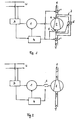
- the electric motor 1 drives a compressor 2.
- a medium eg a cooling liquid, with a low pressure T is compressed in the compressor to a high pressure H.
- the mains voltage monitoring unit 3 continuously measures the mains voltage U and forwards the information to the control arrangement 4.
- the engine is firmly connected to the compressor, inlet E and outlet A of the compressor can be closed with the valves 5, 5 'via the by-pass 7 short.
- the control arrangement 4 causes the valve 5 to be opened and the valves 5 'to be closed.
- the pressure difference between the pressure LP at the inlet E and the pressure HP at the outlet A is thereby reduced within 20 ms, preferably to less than 2 bar, particularly preferably to less than 1 bar, the load on the motor 1 decreases sharply.
- the engine 1 as off Fig. 2 can also be connected via a coupling 6 to the compressor 2.
- the clutch 6 is released and thus the compressor 2 is disconnected from the engine 1.
- the engine 1 is only reconnected to the full load of the compressor 2 when the grid voltage U rises above the second threshold of 90 to 95% of the rated voltage. If this is not the case within 10 to 60 seconds, the motor 1 is switched off and only switched on again when the mains voltage U exceeds the second threshold value. This prevents on the one hand, that the network is charged further, on the other hand, the motor 1 is protected from overheating. After switching on the engine 1 is only then connected to the load of the compressor 2 when it has reached a certain speed, preferably at least 80% of the rated speed.
- the circuit diagram of the preferred electric motor 1 is shown in FIG Fig. 3 shown.
- the motor 1 comprises a main winding 11 and an auxiliary winding 12.
- a hot conductor 15 is switchable.
- an operating capacitor 13 is connected in series with the auxiliary winding 12.
- a starting capacitor 14 can be connected in series with the auxiliary winding 12 with a second hot conductor 16 in series.
- the switches 17 and 18 are operated by the control assembly 20.
- both hot conductors 15 and 16 and the starting capacitor 14 are connected in the circuit.
- the hot conductor 15 reduces the current consumption of the main winding 11 at the moment of the switch-on, the hot conductor 16 through those the starting capacitor 14.
- a capacitive current peak is prevented by switching.
- the phase shift of the currents through the main winding 11 and the auxiliary winding 12 is large, which favors the starting of the engine.
- the start-up capacitor 14 is first removed from the circuit via the switch 18 via the control arrangement, and then the hot conductor 15 is bridged via the switch 17. Then the motor is in normal operation, the phase shift in the auxiliary winding is generated by the operating capacitor 13.
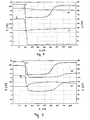
- the current waveform I when switching on a conventional electric motor 1 to a compressor 2 is in Fig. 4 shown.
- the pressure difference between the pressure LP at the inlet E and the pressure HP at the outlet A of the compressor 2 is zero at the time of switch-on.
- the operating capacity of the motor 1 is 35 ⁇ F
- the mains voltage U is 228 V.
- the peak current is 86 A.
- Fig. 5 the same engine 1 is turned on, but the pressure difference between inlet E and outlet A of the compressor 2 is 5.2 bar.
- the peak current is 85 A, the start-up process takes about twice as long. With such an arrangement, the network is heavily loaded at each power-up.
- Fig. 6 indicates the analogous situation Fig. 4 with a motor 1 as in Fig. 3 described, wherein the mains voltage U is 229 V.
- the peak current is only 28 A. If the pressure difference between inlet E and outlet A of compressor 2 is 3.5 bar at the beginning of the switch-on phase, the peak current increases to 51 A, the duration of the switch-on process is approximately doubled.
- the current flow I and the course of the Pressure LP at inlet E and HP at outlet A of condenser 2 are off Fig. 7 seen.
- FIGS. 8 and 9 the consequences of a voltage dip of 230 V to 160 V are shown.
- a conventional device is visible without overload protection. Due to the voltage drop, the motor 1 drops completely and does not restart even when the mains voltage U normalizes. When restarting the engine 1 according to Fig. 5 need a high starting current.
- Fig. 9 the pressure difference between the pressure LP at the inlet E and the pressure HP at the outlet A of the compressor 2 is reduced after the voltage drop within 30 ms to about 1/3 of the original pressure difference.
- the motor 1 thus continues to run at a reduced current I.
- the mains voltage U rises again to the rated voltage, the pressure difference is increased again and the engine 1 continues to run with the normal power consumption.
Landscapes
- Engineering & Computer Science (AREA)
- Mechanical Engineering (AREA)
- General Engineering & Computer Science (AREA)
- Control Of Positive-Displacement Pumps (AREA)
Description
Die Erfindung betrifft eine Anordnung zum Überlastschutz und ein Verfahren zur Reduktion des Stromverbrauchs bei Netzspannungsschwankungen gemäss den unabhängigen Patentansprüchen.The invention relates to an arrangement for overload protection and a method for reducing the power consumption in mains voltage fluctuations according to the independent claims.
Kompressoren zur Kühlung werden üblicherweise mit Elektromotoren angetrieben. Wenn es zu Netzspannungseinbrüchen kommt, können diese Elektromotoren durch den stärkeren Strom überlastet und überhitzt werden. Das kann im Extremfall dazu führen, dass die Motoren zum Stillstand kommen. Dies bedeutet eine Überlastung des Motors und andererseits eine Belastung für das Versorgungsnetz.
Umgekehrt belasten mit Elektromotoren angetriebene Kühlanordnungen das Stromnetz im Normalbetrieb sehr unregelmässig, weil Kompressoren zur Kühlung üblicherweise in einem relativ kurzen Schaltzyklus betrieben werden, z.B. 15 min kühlen und 5 min rasten. Insbesondere herkömmliche Motoren, die während des Anlaufens einen hohen Stromverbrauch aufweisen, wirken destabilisierend auf das Stromnetz. In der Folge kann es zu Netzspannungseinbrüchen kommen, durch welche die Elektromotoren wiederum belastet werden.Compressors for cooling are usually driven by electric motors. When mains voltage dips occur, these electric motors can be overloaded and overheated by the stronger current. In extreme cases, this can cause the motors to come to a standstill. This means an overload of the motor and on the other hand a load on the supply network.
Conversely, cooling arrangements driven by electric motors load the power network very irregularly in normal operation because compressors for cooling are usually operated in a relatively short switching cycle, eg, cool for 15 minutes and lock for 5 minutes. In particular, conventional motors, which have a high power consumption during start-up, have a destabilizing effect on the power grid. As a result, mains voltage dips can occur, which in turn stress the electric motors.
Die
Es ist Aufgabe der Erfindung, die bekannten Probleme zu überwinden, insbesondere beim Antrieb von Kompressoren einen Überlastschutz zu schaffen.It is an object of the invention to overcome the known problems, especially in the drive of compressors to provide overload protection.
Diese Aufgabe wird gelöst mit einer Anordnung zum Überlastschutz eines Elektromotors eines Kompressionsaggregats und einem Verfahren zur Reduktion des Stromverbrauchs bei Netzspannungsschwankungen gemäss den unabhängigen Patentansprüchen.This object is achieved with an arrangement for overload protection of an electric motor of a compression unit and a method for reducing the power consumption at mains voltage fluctuations according to the independent claims.
Die Anordnung zum Überlastschutz eines Elektromotor eines Kompressionsaggregats mit einem Kompressor umfasst den Motor, das Kompressionsaggregat, eine Netzspannungs-Überwachungseinheit, eine Einrichtung zum Reduzieren der Last am Motor und eine Steueranordnung. Die Steueranordnung ist mit der Netzspannungs-Überwachungseinheit und mit der Einrichtung zum Reduzieren der Last am Motor derart verbunden, dass der Motor von der Last getrennt und/oder die Last reduziert wird, sobald die Netzspannung einen vorgegebenen ersten Schwellwert, vorzugsweise 80 bis 90% der Nennspannung, besonders vorteilhaft 85% der Nennspannung, unterschreitet.The arrangement for overload protection of an electric motor of a compression unit with a compressor comprises the motor, the compression unit, a mains voltage monitoring unit, a device for reducing the load on the motor and a control arrangement. The control arrangement is connected to the mains voltage monitoring unit and to the means for reducing the load on the motor such that the motor is disconnected from the load and / or the load is reduced as soon as the mains voltage reaches a predetermined first threshold, preferably 80 to 90% of the load Rated voltage, particularly advantageous 85% of the rated voltage, falls below.
Die Last des Motors wird durch die Kompressor-Arbeit verursacht, die den Druckunterschied zwischen Ein- und Auslass des Kompressors erzeugt. Zum Reduzieren der Last am Motor kann damit der Druckunterschied zwischen Ein- und Auslass des Kompressors reduziert werden. Vorteilhaft geschieht das über einen By-Pass zwischen dem Ein- und Auslass, der mit mindestens einem Ventil geöffnet bzw. geschlossen werden kann.The load of the engine is caused by the compressor work, which creates the pressure difference between inlet and outlet of the compressor. To reduce the load on the engine can thus reduce the pressure difference between the inlet and outlet of the compressor. This is advantageously done via a by-pass between the inlet and outlet, which can be opened or closed with at least one valve.
Alternativ kann der Motor auch über eine Kupplung mit dem Kompressor verbunden sein. Die Last des Kompressors kann über diese Kupplung verstellt, insbesondere reduziert, und/oder ganz vom Motor abgetrennt werden.Alternatively, the engine may also be connected to the compressor via a coupling. The load of the compressor can be adjusted via this coupling, in particular reduced, and / or completely separated from the engine.
Die Netzspannungs-Überwachungseinheit enthält vorteilhaft einen Spannungskomparator. Mit diesem wird die Netzspannung laufend überwacht. Die Ansprechzeit des Spannungskomparators beträgt vorteilsweise maximal 10 ms.The mains voltage monitoring unit advantageously contains a voltage comparator. With this the mains voltage is constantly monitored. The response time of the voltage comparator is advantageously at most 10 ms.
Die Steueranordnung steht vorzugsweise in Wirkverbindung mit einer Einrichtung zum Ausschalten des Elektromotors. Wenn die Unterspannung länger als eine vorgegebene Zeitdauer, z.B. 10 bis 60 s, andauert, wird der Elektromotor ausgeschaltet. Dies verhindert, dass der Motor bei einer lange anhaltenden Störung des Netzbetriebs Strom verbraucht und das Netz somit weiterhin belastet. Ausserdem wird der Motor dadurch vor Überhitzung geschützt.The control arrangement is preferably in operative connection with a device for switching off the electric motor. If the undervoltage is longer than a predetermined period of time, eg 10 to 60 s, the electric motor is switched off. This prevents the motor from consuming power in the event of a long-lasting malfunction of the network operation and thus continuing to load the network. It also protects the engine from overheating.
Besonders bevorzugt ist der Motor mit einer Einrichtung zur Reduktion des Stromverbrauchs in der Anlaufphase versehen. Vorteilhaft ist hierzu die Verwendung von Heissleitern, die seriell in die Haupt- und in die Hilfswicklung eines Einphasen-Elektromotors geschaltet werden können. In der Hilfswicklung ist ein in Serie mit dem Heissleiter geschalteter Anlaufkondensator vorteilhaft, dessen Kapazitätswert rund 3 bis 5 mal grösser ist als jener des Betriebskondesators. Durch den Heissleiter wird der Anfangsstrom durch den Anlaufkondensator beschränkt, was kapazitive Stromspitzen in der Anlaufphase reduziert. Durch die grosse Kapazität des Anlaufkondensators wird eine grosse Phasenverschiebung des Stroms zwischen der Hilfswicklung und der Hauptwicklung erzeugt, was das Anlaufen des Motors erleichtert. Der Heissleiter in der Hauptwicklung reduziert den Anfangsstrom durch die Hauptspule, was ebenfalls für eine Reduktion der Stromaufnahme in der Anlaufphase sorgt. Bei erreichen der Nenndrehzahl werden zuerst der Anlaufkondensator und der dazu vorgeschaltete Heissleiter vom Stromkreis getrennt, erst dann wird der Heissleiter in der Hauptwicklung mittels eines Schalters überbrückt.Particularly preferably, the motor is provided with a device for reducing the power consumption in the start-up phase. Advantageous for this purpose is the use of hot conductors, which can be connected in series in the main and in the auxiliary winding of a single-phase electric motor. In the auxiliary winding, a starting capacitor connected in series with the hot conductor is advantageous, the capacitance value of which is approximately 3 to 5 times greater than that of the operating capacitor. By the hot conductor of the initial current is limited by the starting capacitor, which reduces capacitive current peaks in the start-up phase. Due to the large capacity of the starting capacitor, a large phase shift of the current between the auxiliary winding and the main winding is generated, which facilitates the startup of the engine. The hot conductor in the main winding reduces the initial current through the main coil, which also reduces the current consumption in the start-up phase. When the rated speed is reached, the starting capacitor and the hot conductor connected upstream are first separated from the circuit, only then is the hot conductor in the main winding bridged by means of a switch.
Vorzugsweise ist die Steueranordnung derart mit der Einrichtung zum Einschalten des Motors verbunden, dass der Motor nur dann eingeschaltet wird, wenn die Netzspannung über einem zweiten vorbestimmten Schwellwert, vorzugsweise 90 bis 95% der Netzspannung, liegt. Anderenfalls wird das Einschalten des Motors verhindert. So wird die Netzspannung nicht weiter belastet.Preferably, the control arrangement is connected to the device for switching on the motor such that the motor is only switched on when the mains voltage is above a second predetermined threshold value, preferably 90 to 95% of the mains voltage. Otherwise, switching on the motor is prevented. So the mains voltage is not charged further.
Vorteilhaft wird die Last erst dann mit dem Motor verbunden, wenn dieser eine gewisse vorgegebene Drehzahl erreicht hat. Dies verringert die Stromaufnahme in der Anlaufphase ebenfalls, womit Schwankungen der Netzspannung weiter reduziert werden. Die vorbestimmte Drehzahl ist vorzugsweise die Nenndrehzahl des Motors, sie kann aber auch darunter liegen, z.B. bei 80% der Nenndrehzahl.Advantageously, the load is only then connected to the motor when it has reached a certain predetermined speed. This also reduces the current consumption in the start-up phase, which further reduces fluctuations in the mains voltage. The predetermined speed is preferably the rated speed of the motor, but it may be lower, e.g. at 80% of the rated speed.
Der Kompressor der erfindungsgemässen Vorrichtung ist vorzugsweise in einer Klimaanlage oder einem Kühlschrank eingebaut, weil die durch Kühlanlagen erzeugten Spannungsschwankungen wegen deren kurzen Zyklus relativ gross sind. In Kühlanlagen ist deshalb der Nutzen der erfindungsgemässen Vorrichtung besonders gross.The compressor of the inventive device is preferably installed in an air conditioner or a refrigerator, because the voltage fluctuations generated by refrigeration systems are relatively large because of their short cycle. In refrigerators, therefore, the benefits of the inventive device is particularly large.
Das Verfahren zum Reduzieren des Stromverbrauchs eines Elektromotors an einem Kompressionsaggregat bei Netzspannungsschwankungen, insbesondere bei einer Reduktion der Netzspannung, umfassent die folgenden Schritte:
- Überwachen der Netzspannung
- Reduzieren der Last am Motor durch den Kompressor, wenn die Netzspannung unter einen ersten Schwellwert sinkt, so dass der Motor etwa im Leerlauf betrieben wird.
- Monitor the mains voltage
- Reducing the load on the engine by the compressor when the mains voltage drops below a first threshold, so that the engine is operated approximately at idle.
Die Reduktion der Last am Motor kann realisiert werden, indem die Druckdifferenz zwischen Ein- und Auslass des Kompressors reduziert wird. Besonders vorteilhaft wird diese Druckdifferenz auf Null reduziert, weil dann fast die gesamte Last vom Motor genommen wird. Die Reduktion sollte vorteilhaft innert weniger als 30 ms, besonders vorteilhaft innert etwa 20 ms erfolgen, damit die Reaktionszeit kurz genug ist, um einem starken Spannungseinbruch entgegenzuwirken und um zu verhindern, dass der Motor zum Stillstand kommt.The reduction of the load on the engine can be realized by reducing the pressure difference between the inlet and outlet of the compressor. Particularly advantageously, this pressure difference is reduced to zero, because then almost the entire load is taken from the engine. The reduction should advantageously take place within less than 30 ms, particularly advantageously within about 20 ms, so that the reaction time is short enough to withstand a large voltage dip counteract and prevent the engine from stalling.
Die Druckdifferenz kann durch das Öffnen und/oder Schliessen von einem oder mehreren Ventilen in einem By-Pass zwischen Ein- und Auslass des Kompressors reduziert werden. Dabei ist es vorteilhaft, wenn durch das Öffnen des By-Pass die übrigen Wege des zu komprimierenden Mediums, z.B. Kühlflüssigkeit, geschlossen werden. Damit lasst sich ein Druckabbau im Kühlsystem verhindern.The pressure differential can be reduced by opening and / or closing one or more valves in a by-pass between the inlet and outlet of the compressor. It is advantageous if, by opening the by-pass, the remaining paths of the medium to be compressed, e.g. Coolant, to be closed. This can prevent a pressure reduction in the cooling system.
Alternativ ist es auch möglich, dass die Last über eine Kupplung vom Motor abgekoppelt wird. So wird die Last sehr schnell und vollständig vom Motor genommen, dieser läuft innert kürzester Zeit im Leerlauf.Alternatively, it is also possible that the load is decoupled from the engine via a clutch. Thus, the load is taken very quickly and completely from the engine, this runs within a very short time in idle.
Weiter ist es vorteilhaft, dass die Zeit, während welcher sich der Motor im Leerlauf befindet, gemessen wird, und dass nach einer vorbestimmten Zeitdauer im Leerlauf der Motor ausgeschaltet wird. Damit wird verhindert, dass der Motor bei länger anhaltenden Spannungseinbrüchen die Netzspannung weiterhin belastet oder dass er überhitzt wird. Vorteilsweise liegt diese vorbestimmte Zeitdauer im Bereich von 10 bis 60 s.Further, it is advantageous that the time during which the engine is idling, is measured, and that after a predetermined period of idling the engine is turned off. This prevents the motor from continuing to load the mains voltage during prolonged voltage drops or from overheating. Advantageously, this predetermined period of time is in the range of 10 to 60 s.
Besonders bevorzugt wird ein Elektromotor verwendet, der während der Anlaufphase mit einem reduzierten Strom gespeist werden kann. Dadurch wird die Netzspannung weniger stark belastet, wenn der Motor eingeschaltet wird, als dies bei einem herkömmlichen Motor der Fall wäre.Particularly preferred is an electric motor is used, which can be fed during the start-up phase with a reduced current. As a result, the mains voltage is less heavily loaded when the engine is turned on than would be the case with a conventional engine.
Eine Möglichkeit, einen Elektromotor während der Anlaufphase mit einem reduzierten Strom zu speisen, ist dann gegeben, wenn zum Einschaltzeitpunkt ein Heissleiter in Serie zur Hauptwicklung des Motors geschaltet wird. Dadurch wird der Anfangsstrom durch die Hauptwicklung reduziert. Besonders vorteilhaft wird ausserdem in Serie zur Hilfswicklung eine Anordnung aus einem Heissleiter in Serie zu einem Anlaufkondensator geschaltet. Diese Anordnung sollte parallel zum Betriebskondensator geschaltet sein, damit sich die Kapazitäten addieren und somit während dem Einschaltvorgang eine grosse Phasenverschiebung zwischen der Hauptwicklung und der Hilfswicklung erzeugt wird. Um kapazitive Stromspitzen zu vermeiden, wird der Strom auf den Anlaufkondensator zum Zeitpunkt des Einschaltens durch den Heissleiter beschränkt und erst durch die Erwärmung des Heissleiters erhöht. Wenn im Verlauf des Anlaufens der Rotor-Schlupf des Motors gegen Null geht, wird zuerst die Anordnung in Serie zur Hilfwicklung vom Stromkreis getrennt und danach der Heissleiter in Serie zur Hauptwicklung mittels Schaltern überbrückt. Darauf befindet sich der Motor im Normalbetrieb, die Phasendifferenz zwischen der Haupt- und der Hilfswicklung wird allein durch den Betriebskondensator erzeugt, dessen Kapazität vorzugsweise rund drei bis fünf mal kleiner ist als jene des Anlaufkondensators.One way to feed an electric motor during the start-up phase with a reduced current, is given when switching on a hot conductor in series with the main winding of the motor is switched on. This will cause the initial current to go through reduced the main winding. In addition, an arrangement of a hot conductor in series with a starting capacitor is connected in series with the auxiliary winding in a particularly advantageous manner. This arrangement should be connected in parallel to the operating capacitor so that the capacitances add up and thus a large phase shift is generated between the main winding and the auxiliary winding during the switch-on process. To avoid capacitive current peaks, the current is limited to the starting capacitor at the time of switching on by the hot conductor and only increased by the heating of the hot conductor. If, during the course of starting, the rotor slip of the motor approaches zero, first the arrangement in series with the auxiliary winding is disconnected from the circuit and then the hot conductor is bridged in series with the main winding by means of switches. Then the motor is in normal operation, the phase difference between the main and the auxiliary winding is generated solely by the operating capacitor whose capacity is preferably about three to five times smaller than that of the starting capacitor.
Weiter ist es vorteilhaft, wenn der Elektromotor erst nach Erreichen einer vorbestimmten Drehzahl mit der Last des Kompressors verbunden wird. Dadurch verbraucht der Motor während des Anlaufens ebenfalls weniger Strom. Die vorbestimmte Drehzahl ist vorzugsweise die Nenndrehzahl des Motors, sie kann aber auch darunter liegen.Further, it is advantageous if the electric motor is connected only after reaching a predetermined speed with the load of the compressor. As a result, the engine also consumes less power during startup. The predetermined speed is preferably the rated speed of the engine, but it may also be lower.
Der erste Schwellwert für die Druckreduktion liegt vorzugsweise zwischen 80 und 90% der Nennspannung, besonders vorzugsweise bei 85% der Nennspannung. Der zweite Schwellwert für den Wiederaufbau des Drucks liegt zwischen 90 und 95% der Nennspannung. Damit wird einer Überlastung des Stromnetzwerks effizient entgegengewirkt.The first threshold for the pressure reduction is preferably between 80 and 90% of the rated voltage, more preferably 85% of the rated voltage. The second threshold for rebuilding the pressure is between 90 and 95% of the rated voltage. This effectively counteracts overloading the power network.
Die Erfindung ist im Folgenden anhand von Ausführungsbeispielen und Zeichnungen näher erläutert. Es zeigen:
- Fig. 1:
- schematische Darstellung der erfindungsgemässen Anordnung
- Fig. 2:
- schematische Darstellung einer alternativen Anordnung,
- Fig. 3:
- schematisches Schaltdiagramm eines bevorzugten Elektromotors
- Fig. 4 bis 7:
- Diagramme des Stromverbrauchs des Elektromotors und der Druckdifferenz zwischen Ein- und Auslass des Kompressors,
- Fig. 8 und 9:
- Diagramme des Verlaufs des mittleren Stroms bei einem Spannungseinbruch und der Druckdifferenz zwischen Ein- und Auslass des Kompressors
- Fig. 1:
- schematic representation of the inventive arrangement
- Fig. 2:
- schematic representation of an alternative arrangement,
- 3:
- schematic circuit diagram of a preferred electric motor
- 4 to 7:
- Diagrams of the power consumption of the electric motor and the pressure difference between inlet and outlet of the compressor,
- 8 and 9:
- Diagrams of the course of the average current at a voltage dip and the pressure difference between the inlet and outlet of the compressor
In den Abbildungen
Statt eines By-Pass 7 zwischen dem Einlass E und dem Auslass A des Kompressors 2 kann der Motor 1 wie aus
In beiden Fällen wird der Motor 1 erst wieder mit der vollen Last des Kompressors 2 verbunden, wenn die Netzspannung U über den zweiten Schwellwert von 90 bis 95% der Nennspannung steigt. Wenn dies nicht innert 10 bis 60 s der Fall ist, wird der Motor 1 ausgeschaltet und erst wieder eingeschaltet, wenn die Netzspannung U den zweiten Schwellwert übersteigt. Dies verhindert einerseits, dass das Netz weiter belastet wird, andererseits wird der Motor 1 so vor Überhitzung geschützt. Nach dem Einschalten wird der Motor 1 erst dann mit der Last des Kompressor 2 verbunden, wenn er eine gewisse Drehzahl, vorzugsweise mindestens 80% der Nenndrehzahl, erreicht hat.In both cases, the
Der Schaltplan des bevorzugten Elektromotors 1 ist in
Beim Einschalten des Motors 1 sind beide Heissleiter 15 und 16 und der Anlaufkondensator 14 in den Stromkreis geschaltet. Der Heissleiter 15 reduziert die Stromaufnahme der Hauptwicklung 11 im Moment des Einschaltvorgangs, der Heissleiter 16 jenen durch den Anlaufkondensator 14. Im Anlaufkondensator 14 wird dadurch eine kapazitive Stromspitze bei Einschalten verhindert. Durch die beiden Kondensatoren 13 und 14 ist die Phasenverschiebung der Ströme durch die Hauptwicklung 11 und die Hilfswicklung 12 gross, was das Anlaufen des Motors begünstigt. Sobald der Rotor-Schlupf des Motor gegen Null geht, wird über die Steueranordnung zuerst der Anlaufkondensator 14 über den Schalter 18 aus dem Stromkreis genommen, anschliessend der Heissleiter 15 über den Schalter 17 überbrückt. Dann befindet sich der Motor im Normalbetrieb, die Phasenverschiebung in der Hilfswicklung wird durch den Betriebskondensator 13 erzeugt.When switching on the
Der Stromverlauf I beim Einschalten eines herkömmlichen Elektromotors 1 an einem Kompressor 2 ist in
Aus diesen Abbildungen wird ersichtlich, dass die Stromspitzen also deutlich reduziert werden können, wenn der Motor 1 einerseits nur gestartet wird, wenn die Last am Motor 1 klein ist, und anderseits die Spannungsversorgung des Motors 1 gemäss
In den
In
Claims (22)
- Arrangement for overload protection of an electric motor (1) of a compression unit having a compressor (2), the arrangement having a device (6, 7) for reducing the load on the motor (1) and a control arrangement (4), characterized in that the arrangement furthermore has a mains voltage-monitoring unit (3) and the control arrangement (4), is connected to the device (6, 7) for the purpose of reducing the load in the event of the mains voltage (U) falling below a predetermined, first threshold value.
- Arrangement according to Claim 1, characterized in that at least one pressure-compensating valve (5, 5') is provided on a bypass (7) between the inlet (E) and the outlet (A) of the compressor (2) for reducing the pressure between the pressure (LP) at the inlet (E) and the pressure (HP) at the outlet (A).
- Arrangement according to Claim 1, characterized in that the connection of the electric motor (1) to the compressor (2) is made via a coupling (6) such that it can be adjusted and/or disconnected.
- Arrangement according to one of Claims 1 to 3, characterized in that the mains voltage-monitoring unit (3) has a voltage comparator.
- Arrangement according to one of Claims 1 to 4, characterized in that the control arrangement (4) is in interacting connection with a device for switching the electric motor (1) off, with the result that the electric motor (1) is switched off when the undervoltage lasts longer than a predetermined period of time.
- Arrangement according to one of Claims 1 to 5, characterized in that the electric motor (1) is provided with a device for reducing the current consumption in the start-up phase.
- Arrangement according to Claim 6, characterized in that the device for reducing the current consumption in the start-up phase of the electric motor (1) comprises an NTC thermistor (15) which can be connected in series with a main winding (11), and an arrangement, which can be connected in series with an auxiliary winding (12), comprising an NTC thermistor (16) and a start-up capacitor (17).
- Arrangement according to one of Claims 1 to 7, characterized in that the control arrangement (4) is in interacting connection with a device for switching the electric motor (1) on, with the result that the electric motor (1) is only switched on when the mains voltage (U) rises above a second threshold value.
- Arrangement according to one of the preceding claims, characterized in that the control arrangement (4) is in interacting connection with a device for connecting the electric motor (1) to the load, the load only being connected to the electric motor (1) when it has reached a predetermined speed.
- Arrangement according to one of the preceding claims, characterized in that the compression unit is built into an air-conditioning system or a refrigerator.
- Method for reducing the current consumption of an electric motor (1) using a compression unit in the event of mains voltage fluctuations, in particular in the event of a reduction in the mains voltage (U), comprising the following steps:- monitoring the mains voltage (U)- reducing the load on the electric motor (1) by means of the compressor (2) when the mains voltage (U) falls below a first threshold value, with the result that the electric motor (1) is running on approximately no-load.
- Method according to Claim 11, characterized in that the load is removed from the electric motor (1) by means of reducing the pressure difference between the pressure (LP) at the inlet (E) and the pressure (HP) at the outlet (A) of the compressor (2).
- Method according to Claim 11 or 12, characterized in that the pressure difference between the pressure (LP) at the inlet (E) and the pressure (HP) at the outlet (A) of the compressor (2) is reduced to zero.
- Method according to either of Claims 12 or 13, characterized in that the pressure difference is reduced by opening and/or closing one or more valves (5, 5') in a bypass (7) between the inlet (E) and the outlet (A) of the compressor (2).
- Method according to Claim 11, characterized in that the load is disconnected from the electric motor (1) by means of a coupling (6).
- Method according to one of Claims 11 to 15, characterized in that the time during which the electric motor (1) is on no-load is measured, and in that the electric motor (1) is switched off after a predetermined period of time on no-load.
- Method according to one of Claims 11 to 16, characterized in that the current (I) through the electric motor (1) is reduced during the start-up phase.
- Method according to Claim 17, characterized in that, during the start-up phase, an NTC thermistor (15) is connected in series with a main winding (11), and an arrangement comprising a start-up capacitor (14) in series with an NTC thermistor (16) is connected in series with an auxiliary winding (12).
- Method according to one of Claims 11 to 18, characterized in that the electric motor (1) is only connected to the load of the compressor (2) once a predetermined speed has been reached.
- Method according to one of Claims 11 to 19, characterized in that the first threshold value for reducing the load on the electric motor (1) is 80 to 90% of the rated voltage, preferably 85% of the rated voltage.
- Method according to one of Claims 10 to 20, characterized in that the second threshold value for increasing the load on the electric motor (1) is 90 to 95% of the rated voltage.
- Method according to one of Claims 10 to 21, characterized in that the load on the electric motor (1) is reduced within less than 30 ms, preferably within approximately 20 ms.
Priority Applications (3)
| Application Number | Priority Date | Filing Date | Title |
|---|---|---|---|
| EP03027648.9A EP1538337B1 (en) | 2003-12-02 | 2003-12-02 | Overload protective arrangement and method for reducing power consumption upon voltage fluctuations |
| DK03027648.9T DK1538337T3 (en) | 2003-12-02 | 2003-12-02 | Device for overload protection and method for reducing power consumption in case of fluctuations in mains voltage |
| US11/001,644 US7276870B2 (en) | 2003-12-02 | 2004-12-02 | Arrangement for overload protection and method for reducing the current consumption in the event of mains voltage fluctuations |
Applications Claiming Priority (1)
| Application Number | Priority Date | Filing Date | Title |
|---|---|---|---|
| EP03027648.9A EP1538337B1 (en) | 2003-12-02 | 2003-12-02 | Overload protective arrangement and method for reducing power consumption upon voltage fluctuations |
Publications (2)
| Publication Number | Publication Date |
|---|---|
| EP1538337A1 EP1538337A1 (en) | 2005-06-08 |
| EP1538337B1 true EP1538337B1 (en) | 2014-03-05 |
Family
ID=34442933
Family Applications (1)
| Application Number | Title | Priority Date | Filing Date |
|---|---|---|---|
| EP03027648.9A Expired - Lifetime EP1538337B1 (en) | 2003-12-02 | 2003-12-02 | Overload protective arrangement and method for reducing power consumption upon voltage fluctuations |
Country Status (3)
| Country | Link |
|---|---|
| US (1) | US7276870B2 (en) |
| EP (1) | EP1538337B1 (en) |
| DK (1) | DK1538337T3 (en) |
Families Citing this family (20)
| Publication number | Priority date | Publication date | Assignee | Title |
|---|---|---|---|---|
| US8540493B2 (en) | 2003-12-08 | 2013-09-24 | Sta-Rite Industries, Llc | Pump control system and method |
| KR101116208B1 (en) * | 2004-05-17 | 2012-03-06 | 삼성전자주식회사 | Control apparatus and method for compressor |
| US7874808B2 (en) | 2004-08-26 | 2011-01-25 | Pentair Water Pool And Spa, Inc. | Variable speed pumping system and method |
| US7845913B2 (en) | 2004-08-26 | 2010-12-07 | Pentair Water Pool And Spa, Inc. | Flow control |
| US7686589B2 (en) | 2004-08-26 | 2010-03-30 | Pentair Water Pool And Spa, Inc. | Pumping system with power optimization |
| US7854597B2 (en) | 2004-08-26 | 2010-12-21 | Pentair Water Pool And Spa, Inc. | Pumping system with two way communication |
| US8480373B2 (en) | 2004-08-26 | 2013-07-09 | Pentair Water Pool And Spa, Inc. | Filter loading |
| US8602745B2 (en) | 2004-08-26 | 2013-12-10 | Pentair Water Pool And Spa, Inc. | Anti-entrapment and anti-dead head function |
| US8469675B2 (en) | 2004-08-26 | 2013-06-25 | Pentair Water Pool And Spa, Inc. | Priming protection |
| GB0520470D0 (en) * | 2005-10-07 | 2005-11-16 | Boc Group Plc | Method of operating a pumping system |
| WO2008032225A2 (en) * | 2006-03-21 | 2008-03-20 | Ranco Incorporated Of Delaware | Refrigeration monitor unit |
| JP2008050981A (en) * | 2006-08-23 | 2008-03-06 | Denso Corp | Control device for turbocharger with electric motor |
| EP2154378A1 (en) * | 2008-08-12 | 2010-02-17 | Holger Junkers | Transportable pump system for hydraulic tools |
| ES2773888T3 (en) | 2008-10-06 | 2020-07-15 | Danfoss Low Power Drives | Method of operating a vacuum release safety system |
| US9556874B2 (en) | 2009-06-09 | 2017-01-31 | Pentair Flow Technologies, Llc | Method of controlling a pump and motor |
| BE1019299A3 (en) * | 2010-04-20 | 2012-05-08 | Atlas Copco Airpower Nv | METHOD FOR DRIVING A COMPRESSOR. |
| JP5524285B2 (en) * | 2012-07-10 | 2014-06-18 | 株式会社東芝 | Pumping unit |
| CN104564638B (en) | 2013-10-24 | 2016-08-17 | 珠海格力电器股份有限公司 | Overload of compressor protection control method and device |
| FR3033006A1 (en) * | 2015-02-25 | 2016-08-26 | Faurecia Systemes D'echappement | QUICK DISCHARGE PUMP |
| EP3093981A1 (en) * | 2015-05-12 | 2016-11-16 | Roland Weigel | Device and method for starting an engine for alternating current |
Family Cites Families (13)
| Publication number | Priority date | Publication date | Assignee | Title |
|---|---|---|---|---|
| US3585451A (en) | 1969-12-24 | 1971-06-15 | Borg Warner | Solid state motor overload protection system |
| IT1117586B (en) * | 1979-01-23 | 1986-02-17 | Indesit | TEMPERATURE REGULATION DEVICE FOR DOMESTIC ELECTRICAL APPLIANCES |
| US4510547A (en) * | 1982-11-12 | 1985-04-09 | Johnson Service Company | Multi-purpose compressor controller |
| US4912936A (en) * | 1987-04-11 | 1990-04-03 | Kabushiki Kaisha Toshiba | Refrigeration control system and method |
| US5519301A (en) * | 1992-02-26 | 1996-05-21 | Matsushita Electric Industrial Co., Ltd. | Controlling/driving apparatus for an electrically-driven compressor in a car |
| US5368019A (en) * | 1992-12-16 | 1994-11-29 | Puritan-Bennett Corporation | System and method for operating a respirator compressor system under low voltage conditions |
| US5516265A (en) * | 1994-06-14 | 1996-05-14 | Ingersoll-Rand Company | Interface apparatus for permitting microprocessor-based electronic control of non-electronically controlled air compressors |
| JPH0835712A (en) * | 1994-07-26 | 1996-02-06 | Fujitsu General Ltd | Controller for air conditioner |
| US6020702A (en) * | 1998-01-12 | 2000-02-01 | Tecumseh Products Company | Single phase compressor thermostat with start relay and motor protection |
| US6238188B1 (en) * | 1998-08-17 | 2001-05-29 | Carrier Corporation | Compressor control at voltage and frequency extremes of power supply |
| JP2001061285A (en) * | 1999-08-20 | 2001-03-06 | Fujitsu General Ltd | Starter for induction capacitor motor |
| US6438973B1 (en) * | 2000-05-01 | 2002-08-27 | Hoshizaki America, Inc. | Control board alarms |
| US6616416B1 (en) * | 2002-02-19 | 2003-09-09 | Bristol Compressors, Inc. | Methods and system for motor optimization using capacitance and/or voltage adjustments |
-
2003
- 2003-12-02 EP EP03027648.9A patent/EP1538337B1/en not_active Expired - Lifetime
- 2003-12-02 DK DK03027648.9T patent/DK1538337T3/en active
-
2004
- 2004-12-02 US US11/001,644 patent/US7276870B2/en active Active
Also Published As
| Publication number | Publication date |
|---|---|
| DK1538337T3 (en) | 2014-06-16 |
| US7276870B2 (en) | 2007-10-02 |
| US20050162787A1 (en) | 2005-07-28 |
| EP1538337A1 (en) | 2005-06-08 |
Similar Documents
| Publication | Publication Date | Title |
|---|---|---|
| EP1538337B1 (en) | Overload protective arrangement and method for reducing power consumption upon voltage fluctuations | |
| DE102004020343B4 (en) | Device for controlling the operation of a reciprocating compressor | |
| DE112016000555B4 (en) | Air conditioning device | |
| DE3517217A1 (en) | OPERATING METHOD AND CONTROL ARRANGEMENT FOR A REFRIGERATION SYSTEM | |
| DE60132518T2 (en) | Screw compressor for a refrigeration device | |
| DE10312234A1 (en) | Operating control device and method for a linear compressor | |
| DE4337692C2 (en) | Cooling system for electronic device | |
| DE3517216A1 (en) | METHOD FOR OPERATING A STEAM COMPRESSION REFRIGERATION SYSTEM AND ARRANGEMENT FOR CONTROLLING THE SAME | |
| DE3118638A1 (en) | STARTER AND THERMAL PROTECTIVE DEVICE FOR ENGINE COMPRESSOR BUILDING UNITS OF COOLING DEVICES | |
| DE112014000364B4 (en) | Operating method and variable frequency drive system to avoid overheating | |
| DE102007056461A1 (en) | Heat pump type-hot water supply device, has heat pump controller with current sensor for recording current value of electrical power, where frequency is increased, when current value is smaller than specific regenerative current value | |
| DE102005052042A1 (en) | Method for controlling of compressor in control loop for refrigerating plant, involves consideration of current operating condition of compressor during performance control of compressor | |
| EP1568122B1 (en) | Device and method for reducing the current consumption during the starting process of a single-phase a.c. asynchronous motor | |
| EP1073174A2 (en) | Electrical motor with self-protection against overheating | |
| EP2059739B1 (en) | Refrigerator with forced-ventilation evaporator | |
| DE2847456A1 (en) | STARTER CIRCUIT FOR A COMPRESSOR ARRANGEMENT | |
| DE19938927C1 (en) | Control device for a motor vehicle air conditioning system | |
| WO2015139713A1 (en) | Method for operating a motor | |
| WO2015189010A1 (en) | Refrigeration device having hot gas defrosting, and defrosting method | |
| EP2154452B1 (en) | Cooling device with forced cooling | |
| DE102020003962B4 (en) | Refrigeration system and method for operating a refrigeration system with a fan motor as a heat source | |
| EP2827081B1 (en) | Method for controlling a heat pump | |
| EP0395589B1 (en) | Method and device for limiting the peak load | |
| EP3355007B1 (en) | Cooling device fan and ultra low temperature cooling device | |
| EP2652409B1 (en) | Method for operating a heat pump device |
Legal Events
| Date | Code | Title | Description |
|---|---|---|---|
| PUAI | Public reference made under article 153(3) epc to a published international application that has entered the european phase |
Free format text: ORIGINAL CODE: 0009012 |
|
| AK | Designated contracting states |
Kind code of ref document: A1 Designated state(s): AT BE BG CH CY CZ DE DK EE ES FI FR GB GR HU IE IT LI LU MC NL PT RO SE SI SK TR |
|
| AX | Request for extension of the european patent |
Extension state: AL LT LV MK |
|
| 17P | Request for examination filed |
Effective date: 20051207 |
|
| AKX | Designation fees paid |
Designated state(s): AT BE BG CH CY CZ DE DK EE ES FI FR GB GR HU IE IT LI LU MC NL PT RO SE SI SK TR |
|
| 17Q | First examination report despatched |
Effective date: 20130503 |
|
| GRAP | Despatch of communication of intention to grant a patent |
Free format text: ORIGINAL CODE: EPIDOSNIGR1 |
|
| INTG | Intention to grant announced |
Effective date: 20131003 |
|
| GRAS | Grant fee paid |
Free format text: ORIGINAL CODE: EPIDOSNIGR3 |
|
| GRAA | (expected) grant |
Free format text: ORIGINAL CODE: 0009210 |
|
| AK | Designated contracting states |
Kind code of ref document: B1 Designated state(s): AT BE BG CH CY CZ DE DK EE ES FI FR GB GR HU IE IT LI LU MC NL PT RO SE SI SK TR |
|
| REG | Reference to a national code |
Ref country code: GB Ref legal event code: FG4D Free format text: NOT ENGLISH |
|
| REG | Reference to a national code |
Ref country code: CH Ref legal event code: EP |
|
| REG | Reference to a national code |
Ref country code: AT Ref legal event code: REF Ref document number: 655066 Country of ref document: AT Kind code of ref document: T Effective date: 20140315 |
|
| REG | Reference to a national code |
Ref country code: IE Ref legal event code: FG4D Free format text: LANGUAGE OF EP DOCUMENT: GERMAN |
|
| REG | Reference to a national code |
Ref country code: DE Ref legal event code: R096 Ref document number: 50314992 Country of ref document: DE Effective date: 20140417 |
|
| REG | Reference to a national code |
Ref country code: CH Ref legal event code: NV Representative=s name: HEPP WENGER RYFFEL AG, CH |
|
| REG | Reference to a national code |
Ref country code: DK Ref legal event code: T3 Effective date: 20140610 |
|
| REG | Reference to a national code |
Ref country code: NL Ref legal event code: VDEP Effective date: 20140305 |
|
| PG25 | Lapsed in a contracting state [announced via postgrant information from national office to epo] |
Ref country code: SE Free format text: LAPSE BECAUSE OF FAILURE TO SUBMIT A TRANSLATION OF THE DESCRIPTION OR TO PAY THE FEE WITHIN THE PRESCRIBED TIME-LIMIT Effective date: 20140305 Ref country code: FI Free format text: LAPSE BECAUSE OF FAILURE TO SUBMIT A TRANSLATION OF THE DESCRIPTION OR TO PAY THE FEE WITHIN THE PRESCRIBED TIME-LIMIT Effective date: 20140305 Ref country code: CY Free format text: LAPSE BECAUSE OF FAILURE TO SUBMIT A TRANSLATION OF THE DESCRIPTION OR TO PAY THE FEE WITHIN THE PRESCRIBED TIME-LIMIT Effective date: 20140305 |
|
| PG25 | Lapsed in a contracting state [announced via postgrant information from national office to epo] |
Ref country code: CZ Free format text: LAPSE BECAUSE OF FAILURE TO SUBMIT A TRANSLATION OF THE DESCRIPTION OR TO PAY THE FEE WITHIN THE PRESCRIBED TIME-LIMIT Effective date: 20140305 Ref country code: NL Free format text: LAPSE BECAUSE OF FAILURE TO SUBMIT A TRANSLATION OF THE DESCRIPTION OR TO PAY THE FEE WITHIN THE PRESCRIBED TIME-LIMIT Effective date: 20140305 Ref country code: EE Free format text: LAPSE BECAUSE OF FAILURE TO SUBMIT A TRANSLATION OF THE DESCRIPTION OR TO PAY THE FEE WITHIN THE PRESCRIBED TIME-LIMIT Effective date: 20140305 Ref country code: RO Free format text: LAPSE BECAUSE OF FAILURE TO SUBMIT A TRANSLATION OF THE DESCRIPTION OR TO PAY THE FEE WITHIN THE PRESCRIBED TIME-LIMIT Effective date: 20140305 Ref country code: BG Free format text: LAPSE BECAUSE OF FAILURE TO SUBMIT A TRANSLATION OF THE DESCRIPTION OR TO PAY THE FEE WITHIN THE PRESCRIBED TIME-LIMIT Effective date: 20140605 |
|
| PG25 | Lapsed in a contracting state [announced via postgrant information from national office to epo] |
Ref country code: ES Free format text: LAPSE BECAUSE OF FAILURE TO SUBMIT A TRANSLATION OF THE DESCRIPTION OR TO PAY THE FEE WITHIN THE PRESCRIBED TIME-LIMIT Effective date: 20140305 Ref country code: SK Free format text: LAPSE BECAUSE OF FAILURE TO SUBMIT A TRANSLATION OF THE DESCRIPTION OR TO PAY THE FEE WITHIN THE PRESCRIBED TIME-LIMIT Effective date: 20140305 |
|
| REG | Reference to a national code |
Ref country code: DE Ref legal event code: R097 Ref document number: 50314992 Country of ref document: DE |
|
| PG25 | Lapsed in a contracting state [announced via postgrant information from national office to epo] |
Ref country code: PT Free format text: LAPSE BECAUSE OF FAILURE TO SUBMIT A TRANSLATION OF THE DESCRIPTION OR TO PAY THE FEE WITHIN THE PRESCRIBED TIME-LIMIT Effective date: 20140707 |
|
| PLBE | No opposition filed within time limit |
Free format text: ORIGINAL CODE: 0009261 |
|
| STAA | Information on the status of an ep patent application or granted ep patent |
Free format text: STATUS: NO OPPOSITION FILED WITHIN TIME LIMIT |
|
| 26N | No opposition filed |
Effective date: 20141208 |
|
| REG | Reference to a national code |
Ref country code: DE Ref legal event code: R097 Ref document number: 50314992 Country of ref document: DE Effective date: 20141208 |
|
| PG25 | Lapsed in a contracting state [announced via postgrant information from national office to epo] |
Ref country code: SI Free format text: LAPSE BECAUSE OF FAILURE TO SUBMIT A TRANSLATION OF THE DESCRIPTION OR TO PAY THE FEE WITHIN THE PRESCRIBED TIME-LIMIT Effective date: 20140305 |
|
| PG25 | Lapsed in a contracting state [announced via postgrant information from national office to epo] |
Ref country code: BE Free format text: LAPSE BECAUSE OF NON-PAYMENT OF DUE FEES Effective date: 20141231 |
|
| PG25 | Lapsed in a contracting state [announced via postgrant information from national office to epo] |
Ref country code: LU Free format text: LAPSE BECAUSE OF FAILURE TO SUBMIT A TRANSLATION OF THE DESCRIPTION OR TO PAY THE FEE WITHIN THE PRESCRIBED TIME-LIMIT Effective date: 20141202 |
|
| REG | Reference to a national code |
Ref country code: IE Ref legal event code: MM4A |
|
| PG25 | Lapsed in a contracting state [announced via postgrant information from national office to epo] |
Ref country code: IE Free format text: LAPSE BECAUSE OF NON-PAYMENT OF DUE FEES Effective date: 20141202 |
|
| REG | Reference to a national code |
Ref country code: FR Ref legal event code: PLFP Year of fee payment: 13 |
|
| PG25 | Lapsed in a contracting state [announced via postgrant information from national office to epo] |
Ref country code: MC Free format text: LAPSE BECAUSE OF FAILURE TO SUBMIT A TRANSLATION OF THE DESCRIPTION OR TO PAY THE FEE WITHIN THE PRESCRIBED TIME-LIMIT Effective date: 20140305 |
|
| PG25 | Lapsed in a contracting state [announced via postgrant information from national office to epo] |
Ref country code: GR Free format text: LAPSE BECAUSE OF FAILURE TO SUBMIT A TRANSLATION OF THE DESCRIPTION OR TO PAY THE FEE WITHIN THE PRESCRIBED TIME-LIMIT Effective date: 20140606 |
|
| PG25 | Lapsed in a contracting state [announced via postgrant information from national office to epo] |
Ref country code: HU Free format text: LAPSE BECAUSE OF FAILURE TO SUBMIT A TRANSLATION OF THE DESCRIPTION OR TO PAY THE FEE WITHIN THE PRESCRIBED TIME-LIMIT; INVALID AB INITIO Effective date: 20031202 Ref country code: TR Free format text: LAPSE BECAUSE OF FAILURE TO SUBMIT A TRANSLATION OF THE DESCRIPTION OR TO PAY THE FEE WITHIN THE PRESCRIBED TIME-LIMIT Effective date: 20140305 |
|
| REG | Reference to a national code |
Ref country code: FR Ref legal event code: PLFP Year of fee payment: 14 |
|
| REG | Reference to a national code |
Ref country code: FR Ref legal event code: PLFP Year of fee payment: 15 |
|
| PGFP | Annual fee paid to national office [announced via postgrant information from national office to epo] |
Ref country code: FR Payment date: 20191128 Year of fee payment: 17 Ref country code: DK Payment date: 20191210 Year of fee payment: 17 Ref country code: IT Payment date: 20191209 Year of fee payment: 17 |
|
| PGFP | Annual fee paid to national office [announced via postgrant information from national office to epo] |
Ref country code: AT Payment date: 20191125 Year of fee payment: 17 |
|
| PGFP | Annual fee paid to national office [announced via postgrant information from national office to epo] |
Ref country code: GB Payment date: 20191129 Year of fee payment: 17 |
|
| PGFP | Annual fee paid to national office [announced via postgrant information from national office to epo] |
Ref country code: CH Payment date: 20200225 Year of fee payment: 17 |
|
| REG | Reference to a national code |
Ref country code: DK Ref legal event code: EBP Effective date: 20201231 |
|
| REG | Reference to a national code |
Ref country code: CH Ref legal event code: PL |
|
| REG | Reference to a national code |
Ref country code: AT Ref legal event code: MM01 Ref document number: 655066 Country of ref document: AT Kind code of ref document: T Effective date: 20201202 |
|
| GBPC | Gb: european patent ceased through non-payment of renewal fee |
Effective date: 20201202 |
|
| PG25 | Lapsed in a contracting state [announced via postgrant information from national office to epo] |
Ref country code: AT Free format text: LAPSE BECAUSE OF NON-PAYMENT OF DUE FEES Effective date: 20201202 Ref country code: IT Free format text: LAPSE BECAUSE OF NON-PAYMENT OF DUE FEES Effective date: 20201202 Ref country code: FR Free format text: LAPSE BECAUSE OF NON-PAYMENT OF DUE FEES Effective date: 20201231 |
|
| PG25 | Lapsed in a contracting state [announced via postgrant information from national office to epo] |
Ref country code: LI Free format text: LAPSE BECAUSE OF NON-PAYMENT OF DUE FEES Effective date: 20201231 Ref country code: GB Free format text: LAPSE BECAUSE OF NON-PAYMENT OF DUE FEES Effective date: 20201202 Ref country code: CH Free format text: LAPSE BECAUSE OF NON-PAYMENT OF DUE FEES Effective date: 20201231 |
|
| PG25 | Lapsed in a contracting state [announced via postgrant information from national office to epo] |
Ref country code: DK Free format text: LAPSE BECAUSE OF NON-PAYMENT OF DUE FEES Effective date: 20201231 |
|
| PGFP | Annual fee paid to national office [announced via postgrant information from national office to epo] |
Ref country code: DE Payment date: 20211116 Year of fee payment: 19 |
|
| REG | Reference to a national code |
Ref country code: DE Ref legal event code: R119 Ref document number: 50314992 Country of ref document: DE |
|
| PG25 | Lapsed in a contracting state [announced via postgrant information from national office to epo] |
Ref country code: DE Free format text: LAPSE BECAUSE OF NON-PAYMENT OF DUE FEES Effective date: 20230701 |