EP1536619B1 - System and method for recording audio and video data in a mobile communication terminal - Google Patents
System and method for recording audio and video data in a mobile communication terminal Download PDFInfo
- Publication number
- EP1536619B1 EP1536619B1 EP04027701A EP04027701A EP1536619B1 EP 1536619 B1 EP1536619 B1 EP 1536619B1 EP 04027701 A EP04027701 A EP 04027701A EP 04027701 A EP04027701 A EP 04027701A EP 1536619 B1 EP1536619 B1 EP 1536619B1
- Authority
- EP
- European Patent Office
- Prior art keywords
- microphone
- camera
- mobile terminal
- unit
- video
- Prior art date
- Legal status (The legal status is an assumption and is not a legal conclusion. Google has not performed a legal analysis and makes no representation as to the accuracy of the status listed.)
- Not-in-force
Links
Images
Classifications
-
- H—ELECTRICITY
- H04—ELECTRIC COMMUNICATION TECHNIQUE
- H04N—PICTORIAL COMMUNICATION, e.g. TELEVISION
- H04N7/00—Television systems
- H04N7/14—Systems for two-way working
- H04N7/141—Systems for two-way working between two video terminals, e.g. videophone
- H04N7/142—Constructional details of the terminal equipment, e.g. arrangements of the camera and the display
-
- H—ELECTRICITY
- H04—ELECTRIC COMMUNICATION TECHNIQUE
- H04B—TRANSMISSION
- H04B1/00—Details of transmission systems, not covered by a single one of groups H04B3/00 - H04B13/00; Details of transmission systems not characterised by the medium used for transmission
- H04B1/38—Transceivers, i.e. devices in which transmitter and receiver form a structural unit and in which at least one part is used for functions of transmitting and receiving
- H04B1/40—Circuits
-
- H—ELECTRICITY
- H04—ELECTRIC COMMUNICATION TECHNIQUE
- H04M—TELEPHONIC COMMUNICATION
- H04M1/00—Substation equipment, e.g. for use by subscribers
- H04M1/64—Automatic arrangements for answering calls; Automatic arrangements for recording messages for absent subscribers; Arrangements for recording conversations
- H04M1/65—Recording arrangements for recording a message from the calling party
- H04M1/656—Recording arrangements for recording a message from the calling party for recording conversations
-
- H—ELECTRICITY
- H04—ELECTRIC COMMUNICATION TECHNIQUE
- H04M—TELEPHONIC COMMUNICATION
- H04M1/00—Substation equipment, e.g. for use by subscribers
- H04M1/72—Mobile telephones; Cordless telephones, i.e. devices for establishing wireless links to base stations without route selection
- H04M1/724—User interfaces specially adapted for cordless or mobile telephones
- H04M1/72403—User interfaces specially adapted for cordless or mobile telephones with means for local support of applications that increase the functionality
-
- H—ELECTRICITY
- H04—ELECTRIC COMMUNICATION TECHNIQUE
- H04M—TELEPHONIC COMMUNICATION
- H04M1/00—Substation equipment, e.g. for use by subscribers
- H04M1/02—Constructional features of telephone sets
- H04M1/0202—Portable telephone sets, e.g. cordless phones, mobile phones or bar type handsets
- H04M1/0206—Portable telephones comprising a plurality of mechanically joined movable body parts, e.g. hinged housings
- H04M1/0208—Portable telephones comprising a plurality of mechanically joined movable body parts, e.g. hinged housings characterized by the relative motions of the body parts
- H04M1/0214—Foldable telephones, i.e. with body parts pivoting to an open position around an axis parallel to the plane they define in closed position
- H04M1/0216—Foldable in one direction, i.e. using a one degree of freedom hinge
- H04M1/0218—The hinge comprising input and/or output user interface means
-
- H—ELECTRICITY
- H04—ELECTRIC COMMUNICATION TECHNIQUE
- H04M—TELEPHONIC COMMUNICATION
- H04M1/00—Substation equipment, e.g. for use by subscribers
- H04M1/02—Constructional features of telephone sets
- H04M1/03—Constructional features of telephone transmitters or receivers, e.g. telephone hand-sets
-
- H—ELECTRICITY
- H04—ELECTRIC COMMUNICATION TECHNIQUE
- H04M—TELEPHONIC COMMUNICATION
- H04M1/00—Substation equipment, e.g. for use by subscribers
- H04M1/02—Constructional features of telephone sets
- H04M1/23—Construction or mounting of dials or of equivalent devices; Means for facilitating the use thereof
- H04M1/236—Construction or mounting of dials or of equivalent devices; Means for facilitating the use thereof including keys on side or rear faces
-
- H—ELECTRICITY
- H04—ELECTRIC COMMUNICATION TECHNIQUE
- H04M—TELEPHONIC COMMUNICATION
- H04M2250/00—Details of telephonic subscriber devices
- H04M2250/52—Details of telephonic subscriber devices including functional features of a camera
-
- H—ELECTRICITY
- H04—ELECTRIC COMMUNICATION TECHNIQUE
- H04N—PICTORIAL COMMUNICATION, e.g. TELEVISION
- H04N7/00—Television systems
- H04N7/14—Systems for two-way working
- H04N7/141—Systems for two-way working between two video terminals, e.g. videophone
- H04N7/142—Constructional details of the terminal equipment, e.g. arrangements of the camera and the display
- H04N2007/145—Handheld terminals
Definitions
- the present invention relates to a system and method in a mobile communication terminal for recording audio and video.
- a mobile terminal having a camera that records video and directs a microphone for recording a corresponding audio from its source is disclosed.
- a mobile communication system such as a mobile terminal is mounted with a camera, multimedia player, or the like to implement a variety of functions such as a multimedia communication, voice communication, or short message service.
- a conventional mobile terminal has either an internally mounted camera or an externally mounted camera. The mobile terminal not only takes still images using the camera, but the terminal records video and audio as well.
- a conventional mobile communication terminal including a main body unit 10, keypad 11, a microphone 12, a camera 14, a folder unit 15, a display unit 16, and a speaker 17.
- the main body unit 10 connects to a keypad 11 for inputting user commands.
- the microphone 12 is mounted on the main body unit 10.
- the folder unit 15 is coupled to one end of the main body unit 10 utilizing a hinge unit 13.
- the folder unit 15 rotates, using the hinge unit 13, about the main body unit 17.
- the display unit 16 and the speaker 17 mount to the folder unit 15.
- the folder unit 15 when opened has a display 16 facing a rear direction of the mobile terminal.
- the camera 14 is mounted or disposed within the hinge unit 13. An image, for example, of a person or an object may be recorded by the camera 14 in a front direction and a rear direction of the mobile terminal.
- the front direction of the mobile terminal is an opposite direction from that of the rear direction.
- the camera 14 rotates about the hinge unit 13 to face an object in a front direction of the mobile terminal.
- the mobile terminal records and outputs to the display unit 16 an image of the object located in a front direction of the mobile terminal. The image is not inverted.
- a user rotates the camera 14 about the hinge unit 13 directing the camera 14 toward an object positioned to a rear direction of the mobile terminal.
- the user records the image of the object.
- the image is outputted to the display unit 16.
- the image is vertically flipped.
- the user may flip the image from top to bottom to create a non-inverted image using a key or a keypad on the main body unit.
- a volume of the audio input recorded through the microphone 12 located in the rear direction of the mobile terminal is undesirably low.
- a user may rotate the camera 14 in the direction of the microphone 12, which rotation results in the display unit 16 facing the object. In this position, a user cannot observe the image of the object being recorded because the display unit 16 faces the object.
- US 6,567,677 discloses a notebook computer telephone comprising a hinge and two hinged parts which open in a book-like configuration.
- On the inside of a first hinged part is a display portion, and on the inside of a second hinged part is a keyboard.
- First and second microphones are disposed on opposite sides of the hinged portion such that, when the hinged parts are opened, the first microphone is disposed on an outside surface of the hinge and the second microphone is disposed on an inside surface of the hinge.
- a camera is disposed on a surface of the first hinged part in a corner outside the display portion. In a second embodiment, the camera is disposed on a part that is rotatable with respect to the hinge along an axis of the hinge.
- the camera is disposed on a surface of a part which rotates with respect to the second hinged part around an axis parallel to the hinge.
- the camera is disposed on a first surface of the rotating part.
- the second microphone is disposed on an inside surface of the hinge.
- the first microphone is disposed on an outer surface of the second hinged part.
- a switch senses a position of the hinge and controls which microphone is used for input according to the sensed position of the hinge.
- JP 2001/169158 discloses a portable image recorder having two microphones disposed on opposite sides of a body having a rotating camera part attached thereto.
- the signal of a first microphone is subtracted from a signal of a second microphone to remove background noise from audio recordings.
- the primary microphone is selected according to direction detecting means for detecting a direction of the camera.
- US 5,550,754 discloses a combination video camera and video conferencing terminal having a display portion on a first side of a main body thereof.
- a unit comprising a camera and a microphone can be rotated about two axes with respect to the main body for teleconferencing and video recording, respectively.
- a mobile telephone can be connected to the terminal and can be used as a remote speaker phone to allow a user to participate in a conference call.
- US 2004/192421 discloses a mobile telephone including a camera and a microphone on a front side, and a camera on a backside.
- the sensitivity of the microphone is normal when camera is selected, and the sensitivity of the microphone is enhanced when camera is selected.
- a second microphone is disposed on a backside of the mobile terminal.
- a camera and microphone are disposed on a rotating hinge part.
- JP 2004/166159 discloses a clamshell type mobile terminal having a first camera and a first microphone disposed on inside portions of a first display portion and a second keypad portion, respectively. Additionally, a second camera and a second microphone are disposed on outside portions of the first display portion and the second keypad portion, respectively.
- the present invention provides a mobile communication terminal for recording video and corresponding audio.
- a microphone of the mobile terminal is positioned to receive audio associated with a video being recorded.
- a keypad faces a user for easy manipulation by a user from the mobile terminal.
- a system may comprise a camera disposed on a mobile terminal for recording video, a first microphone disposed on the mobile terminal for receiving an audio from a first direction of the mobile terminal; and, a second microphone disposed on the mobile terminal for receiving the audio from a second direction of the mobile terminal.
- the system may be further provided with a body unit having a keypad for inputting a user command, wherein the first microphone mounts to a surface of the body unit.
- the system may be further provided with a folder unit rotationally connected at one end of the body unit, wherein the second microphone mounts to a surface of the folder unit.
- a method may comprise determining whether a video mode of the mobile terminal is set, operating a microphone preset in the mobile terminal first if the video mode is set, and determining whether a signal for changing a camera direction is inputted.
- the method may further provide operating a different microphone having its direction corresponding to the camera direction if the signal for changing the camera direction is inputted.
- the method may further provide operating the microphone for voice communication regardless of the camera direction if the video mode is not set.
- the signal for changing the camera direction is inputted through a pre-determined key set to compensate the image outputted to the display unit in accordance with the camera direction.
- the signal for changing the camera direction is inputted through a position sensor for automatically detecting the camera direction or a position switch.
- Fig. 1 is a perspective view illustrating a conventional mobile communication phone.
- Fig. 2A is a perspective view illustrating when an object and an audio source are positioned in a front direction of the mobile communication terminal.
- Fig. 2B is a perspective view illustrating when an object and an audio source are positioned in a rear direction of the mobile communication terminal.
- Fig. 3 is a block diagram illustrating a mobile communication terminal in accordance with the present invention.
- the present invention relates to a system and method for positioning a microphone while recording video in a mobile communication system.
- the invention relates to positioning a microphone substantially along the same direction as the source of audio while recording video of objects or persons.
- a mobile terminal includes a body unit such as a main body unit 20 rotationally connected to a folder unit 25.
- the rotational connection in this example, is a hinge 23.
- the main body unit 20 includes a keypad 21 for inputting a user's command and a first microphone 22, for example a body microphone, for inputting a user's voice or output from an audio source.
- the folder unit 25 includes a display unit 26, a speaker 27 and a second microphone unit 28, such as a folder microphone.
- the display unit 26 and the speaker 27, in this example, are mounted to the main body unit 20.
- the second microphone 28 is disposed or mounted to a surface opposite to that of the display unit 26 and the speaker 27.
- a side-key 29 attaches to a side of the main body unit 20 for flipping from top to bottom an image outputted to the display unit 26.
- the second microphone receives an audio signal from an audio source positioned at a front of the mobile terminal.
- the first microphone 22 and/or the second microphone 28 are selectively driven corresponding to a direction that the camera 24 faces.
- a digital switching unit controls the first microphone 22 and/or the second microphone 28 depending on received signals defined by the location of audio sound.
- a subject and an audio source are positioned in a front direction of the mobile terminal.
- a user rotates the camera 24 about the hinge 23.
- the camera 24 rotates to face the subject.
- the camera 24 records and outputs an image (A) to the display unit 26.
- the display unit 26 outputs the image (A).
- the image (A) is a non-inverted image substantially identical to that of the subject.
- a video function of the mobile terminal is set for operating, in this state, the camera 24, and the second microphone 28.
- a subject and an audio source are positioned in a rear direction of the mobile terminal corresponding to that which the keypad 21 faces.
- the camera 24 rotates to face the subject.
- the camera 24 records and outputs an image (B) to the display unit 26.
- the display unit 26 outputs an image (B) substantially identical to an inverted image or a flipped image of the subject.
- the flipped image is changed into the normal image by a user pressing the side-key 29.
- a video function of the mobile terminal is set for outputting the video of the subject through the camera 24, and operating the first microphone 22.
- a mobile terminal is switched to video mode and a video of a subject is recorded.
- the microphone positioned in a front direction of the mobile terminal initially receives an audio input. If a mobile terminal is switched to video mode, the second microphone 28 positioned at the front of the mobile communication terminal is operated, and the image outputted to the display unit 26.
- a block diagram illustrates a camera unit 10, a digital switching unit 40, a control unit 20, and the microphone units 31, 32 of the present invention.
- the camera unit 10 is provided inputs for directional information of the camera.
- the control unit 20 outputs control signals for selecting the microphone units 31, 32 according to the directional information of the camera unit 10.
- the digital switching unit 40 selectively connects to the first microphone unit 31 and the second microphone unit 32 in accordance with a control signal.
- the digital switching unit 40 at one end connects to an inner switch which operates a microphone output terminal (Mic_+ and Mic_-) of the control unit 20.
- the digital switching unit 40 at the other end connects to the first microphone unit 31 and/or the second microphone unit 32.
- An inner switch is controlled, for example, by a General Purpose Input Output terminal (GPIO_0 and GPIO_1).
- Directional information, associated with controlling an image is received from the camera 24 and/or instructions to modify the image are received through the side-key 29 of a mobile terminal.
- the image is displayed on the display unit 26.
- the control unit 20 outputs a control signal for controlling the digital switching unit 40.
- the control unit 20 uses information from the camera unit 10 and the directional information associated with the camera.
- control unit 20 detects the direction of the camera 24 being rotated to the rear and the side-key 29 being pressed to change top and bottom of the image outputted to the display unit 26.
- the control unit 20 outputs a control signal connecting the inner switch of a digital switching unit 40 to the first microphone 31.
- the digital switching unit 40 operates the first microphone 22.
- the second microphone 28 installed at the folder unit 25 is automatically operated according to the basic setting of the video mode.
- the method for selecting a microphone for receiving audio from video comprises inputting directional information of a camera 10 to a control unit 20, and outputting a control signal from a control unit 20 for selecting a first microphone unit 31 and/or second microphone unit 32.
- the control signal includes the directional information provide by the camera unit 10.
- the method further comprises connecting selectively a digital switching unit 40 to the first microphone unit 31 or the second microphone unit 32 according to the control signal.
- the digital switching unit 40 selects both the first microphone unit 31 and second microphone unit 32.
- Software mounted at the control unit can include a method that the user can select the operation of the microphones by the hand according to circumstances as well as the method that recording of a voice is optimized by automatically coordinating the direction for recording video by the camera with the direction of the chosen microphone.
- This system provides a user pressing the side-key for flipping from top to bottom the displayed image, a first microphone or a second microphone along a direction corresponding to the position of the subject and the audio source.
- Input commands to a keypad or a camera choose which microphone records audio corresponding to video.
- This keypad or camera provides the mobile terminal ability to control the microphones positioned near to the audio source receiving the audio.
- the mobile terminal provides a solution by mounting at least one microphone on an outer surface of the folder unit for having the microphones selectively operated corresponding to the direction of the camera.
- the mobile terminal of the present invention provides a solution for optimizing the volume received for a video through recording an audio using a microphone at a position corresponding to the direction of the camera and/or direction of the audio source.
- the present invention is described in the context of a mobile terminal, the present invention may also be used in any wired or wireless communication systems using mobile devices, such as PDAs and laptop computers equipped with wired and wireless wireless communication capabilities. Moreover, the use of certain terms to describe the present invention should not limit the scope of the present invention to certain type of wireless communication system, such as UMTS. The present invention is also applicable to other wireless communication systems using different air interfaces and/or physical layers, for example, TDMA, CDMA, FDMA, WCDMA, etc.
- the preferred embodiments may be implemented as a method, system or article of manufacture using standard programming and/or engineering techniques to produce software, firmware, hardware, or any combination thereof.
- article of manufacture refers to code or logic implemented in hardware logic (e.g., an integrated circuit chip, Field Programmable Gate Array (FPGA), Application Specific Integrated Circuit (ASIC), etc.) or a computer readable medium (e.g., magnetic storage medium (e.g., hard disk drives, floppy disks, tape, etc.), optical storage (CD-ROMs, optical disks, etc.), volatile and non-volatile memory devices (e.g., EEPROMs, ROMs, PROMs, RAMs, DRAMs, SRAMs, firmware, programmable logic, etc.).
- FPGA Field Programmable Gate Array
- ASIC Application Specific Integrated Circuit
- Code in the computer readable medium is accessed and executed by a processor.
- the code in which preferred embodiments are implemented may further be accessible through a transmission media or from a file server over a network.
- the article of manufacture in which the code is implemented may comprise a transmission media, such as a network transmission line, wireless transmission media, signals propagating through space, radio waves, infrared signals, etc.
- a transmission media such as a network transmission line, wireless transmission media, signals propagating through space, radio waves, infrared signals, etc.
Landscapes
- Engineering & Computer Science (AREA)
- Signal Processing (AREA)
- Computer Networks & Wireless Communication (AREA)
- Multimedia (AREA)
- Human Computer Interaction (AREA)
- Telephone Set Structure (AREA)
- Telephone Function (AREA)
- Studio Devices (AREA)
Description
- The present invention relates to a system and method in a mobile communication terminal for recording audio and video. In particular, a mobile terminal having a camera that records video and directs a microphone for recording a corresponding audio from its source is disclosed.
- A mobile communication system such as a mobile terminal is mounted with a camera, multimedia player, or the like to implement a variety of functions such as a multimedia communication, voice communication, or short message service. A conventional mobile terminal has either an internally mounted camera or an externally mounted camera. The mobile terminal not only takes still images using the camera, but the terminal records video and audio as well.
- Referring to
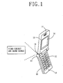
Fig. 1 , a conventional mobile communication terminal is illustrated including amain body unit 10,keypad 11, amicrophone 12, acamera 14, afolder unit 15, adisplay unit 16, and aspeaker 17. Themain body unit 10 connects to akeypad 11 for inputting user commands. Themicrophone 12 is mounted on themain body unit 10. Thefolder unit 15 is coupled to one end of themain body unit 10 utilizing ahinge unit 13. Thefolder unit 15 rotates, using thehinge unit 13, about themain body unit 17. Thedisplay unit 16 and thespeaker 17 mount to thefolder unit 15. Thefolder unit 15 when opened has adisplay 16 facing a rear direction of the mobile terminal. - The
camera 14 is mounted or disposed within thehinge unit 13. An image, for example, of a person or an object may be recorded by thecamera 14 in a front direction and a rear direction of the mobile terminal. The front direction of the mobile terminal is an opposite direction from that of the rear direction. - The
camera 14 rotates about thehinge unit 13 to face an object in a front direction of the mobile terminal. The mobile terminal records and outputs to thedisplay unit 16 an image of the object located in a front direction of the mobile terminal. The image is not inverted. - In another example, a user rotates the
camera 14 about thehinge unit 13 directing thecamera 14 toward an object positioned to a rear direction of the mobile terminal. The user records the image of the object. The image is outputted to thedisplay unit 16. The image is vertically flipped. The user may flip the image from top to bottom to create a non-inverted image using a key or a keypad on the main body unit. - When an object and an audio input for recording are located in a front direction of the mobile terminal, a volume of the audio input recorded through the
microphone 12 located in the rear direction of the mobile terminal is undesirably low. A user may rotate thecamera 14 in the direction of themicrophone 12, which rotation results in thedisplay unit 16 facing the object. In this position, a user cannot observe the image of the object being recorded because thedisplay unit 16 faces the object. - Other conventional mobile terminals have a display unit that rotates vertically as well as horizontally. However, these conventional mobile terminals have an spatially large hinge connection. This connection undesirably increases the size of the mobile terminal. Additionally users of the conventional mobile terminals having this large hinge connection have difficulty manipulating a keypad for inputting volume selection, lightness control, and color control. This difficulty is caused by the keypad facing away from a user and toward an object, even though the display unit is rotated.
-
US 6,567,677 discloses a notebook computer telephone comprising a hinge and two hinged parts which open in a book-like configuration. On the inside of a first hinged part is a display portion, and on the inside of a second hinged part is a keyboard. First and second microphones are disposed on opposite sides of the hinged portion such that, when the hinged parts are opened, the first microphone is disposed on an outside surface of the hinge and the second microphone is disposed on an inside surface of the hinge. A camera is disposed on a surface of the first hinged part in a corner outside the display portion. In a second embodiment, the camera is disposed on a part that is rotatable with respect to the hinge along an axis of the hinge. In a third embodiment, the camera is disposed on a surface of a part which rotates with respect to the second hinged part around an axis parallel to the hinge. The camera is disposed on a first surface of the rotating part. Like the first and second embodiments, the second microphone is disposed on an inside surface of the hinge. However, the first microphone is disposed on an outer surface of the second hinged part. A switch senses a position of the hinge and controls which microphone is used for input according to the sensed position of the hinge. -
JP 2001/169158 -
US 5,550,754 discloses a combination video camera and video conferencing terminal having a display portion on a first side of a main body thereof. A unit comprising a camera and a microphone can be rotated about two axes with respect to the main body for teleconferencing and video recording, respectively. Additionally, a mobile telephone can be connected to the terminal and can be used as a remote speaker phone to allow a user to participate in a conference call. -
US 2004/192421 discloses a mobile telephone including a camera and a microphone on a front side, and a camera on a backside. The sensitivity of the microphone is normal when camera is selected, and the sensitivity of the microphone is enhanced when camera is selected. In a second embodiment, a second microphone is disposed on a backside of the mobile terminal. In a third embodiment a camera and microphone are disposed on a rotating hinge part. -
JP 2004/166159 - Therefore, there is a need for a system that overcomes the above problems and provides advantages over other systems.
- Features and advantages of the invention will be set forth in the description which follows, and in part will be apparent from the description, or may be learned by practice of the invention. The objectives and other advantages of the invention will be realized and attained by the structure particularly pointed out in the written description and claims hereof as well as the appended drawings.
- The present invention provides a mobile communication terminal for recording video and corresponding audio. A microphone of the mobile terminal is positioned to receive audio associated with a video being recorded. A keypad faces a user for easy manipulation by a user from the mobile terminal.
- In one embodiment, a system according to claim 1 is provided. The system may comprise a camera disposed on a mobile terminal for recording video, a first microphone disposed on the mobile terminal for receiving an audio from a first direction of the mobile terminal; and, a second microphone disposed on the mobile terminal for receiving the audio from a second direction of the mobile terminal. The system may be further provided with a body unit having a keypad for inputting a user command, wherein the first microphone mounts to a surface of the body unit.
- The system may be further provided with a folder unit rotationally connected at one end of the body unit, wherein the second microphone mounts to a surface of the folder unit.
- In another embodiment, a method according to claim 5 is provided. The method may comprise determining whether a video mode of the mobile terminal is set, operating a microphone preset in the mobile terminal first if the video mode is set, and determining whether a signal for changing a camera direction is inputted. The method may further provide operating a different microphone having its direction corresponding to the camera direction if the signal for changing the camera direction is inputted.
- The method may further provide operating the microphone for voice communication regardless of the camera direction if the video mode is not set. The signal for changing the camera direction is inputted through a pre-determined key set to compensate the image outputted to the display unit in accordance with the camera direction. In one variation, the signal for changing the camera direction is inputted through a position sensor for automatically detecting the camera direction or a position switch.
- Additional features and advantages of the invention will be set forth in the description which follows, and in part will be apparent from the description, or may be learned by practice of the invention. It is to be understood that both the foregoing general description and the following detailed description of the present invention are exemplary and explanatory and are intended to provide further explanation of the invention as claimed.
- These and other embodiments will also become readily apparent to those skilled in the art from the following detailed description of the embodiments having reference to the attached figures, the invention not being limited to any particular embodiments disclosed.
- The accompanying drawings, which are included to provide a further understanding of the invention and are incorporated in and constitute a part of this specification, illustrate embodiments of the invention and together with the description serve to explain the principles of the invention.
- Features, elements, and aspects of the invention that are referenced by the same numerals in different figures represent the same, equivalent, or similar features, elements, or aspects in accordance with one or more embodiments.
-
Fig. 1 is a perspective view illustrating a conventional mobile communication phone. -
Fig. 2A is a perspective view illustrating when an object and an audio source are positioned in a front direction of the mobile communication terminal. -
Fig. 2B is a perspective view illustrating when an object and an audio source are positioned in a rear direction of the mobile communication terminal. -
Fig. 3 is a block diagram illustrating a mobile communication terminal in accordance with the present invention. - The present invention relates to a system and method for positioning a microphone while recording video in a mobile communication system. The invention relates to positioning a microphone substantially along the same direction as the source of audio while recording video of objects or persons.
- Although the invention is illustrated with respect to a mobile terminal for recording audio corresponding to a video, it is contemplated that the invention may be utilized anywhere it is desired for transmitting, receiving, or processing audio and/or video signals from one location to another location. Reference will now be made in detail to the preferred embodiments of the present invention, examples of which are illustrated in the accompanying drawings.
- Referring to
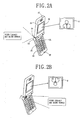
Figs. 2A , a mobile terminal includes a body unit such as amain body unit 20 rotationally connected to afolder unit 25. The rotational connection, in this example, is ahinge 23. Themain body unit 20 includes akeypad 21 for inputting a user's command and afirst microphone 22, for example a body microphone, for inputting a user's voice or output from an audio source. - The
folder unit 25 includes adisplay unit 26, aspeaker 27 and a second microphone unit 28, such as a folder microphone. Thedisplay unit 26 and thespeaker 27, in this example, are mounted to themain body unit 20. The second microphone 28 is disposed or mounted to a surface opposite to that of thedisplay unit 26 and thespeaker 27. A side-key 29 attaches to a side of themain body unit 20 for flipping from top to bottom an image outputted to thedisplay unit 26. - The second microphone receives an audio signal from an audio source positioned at a front of the mobile terminal. When recording a video, the
first microphone 22 and/or the second microphone 28 are selectively driven corresponding to a direction that the camera 24 faces. A digital switching unit controls thefirst microphone 22 and/or the second microphone 28 depending on received signals defined by the location of audio sound. - In one example, a subject and an audio source are positioned in a front direction of the mobile terminal. A user rotates the camera 24 about the
hinge 23. The camera 24 rotates to face the subject. The camera 24 records and outputs an image (A) to thedisplay unit 26. Thedisplay unit 26 outputs the image (A). The image (A) is a non-inverted image substantially identical to that of the subject. A video function of the mobile terminal is set for operating, in this state, the camera 24, and the second microphone 28. - Referring to
Figure 2B , a subject and an audio source are positioned in a rear direction of the mobile terminal corresponding to that which thekeypad 21 faces. The camera 24 rotates to face the subject. The camera 24 records and outputs an image (B) to thedisplay unit 26. Thedisplay unit 26 outputs an image (B) substantially identical to an inverted image or a flipped image of the subject. The flipped image is changed into the normal image by a user pressing the side-key 29. A video function of the mobile terminal is set for outputting the video of the subject through the camera 24, and operating thefirst microphone 22. - In other words, a mobile terminal is switched to video mode and a video of a subject is recorded. The microphone positioned in a front direction of the mobile terminal initially receives an audio input. If a mobile terminal is switched to video mode, the second microphone 28 positioned at the front of the mobile communication terminal is operated, and the image outputted to the
display unit 26. - Referring to
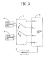
Fig. 3 , a block diagram illustrates acamera unit 10, adigital switching unit 40, acontrol unit 20, and themicrophone units camera unit 10 is provided inputs for directional information of the camera. Thecontrol unit 20 outputs control signals for selecting themicrophone units camera unit 10. Thedigital switching unit 40 selectively connects to thefirst microphone unit 31 and thesecond microphone unit 32 in accordance with a control signal. - The
digital switching unit 40 at one end connects to an inner switch which operates a microphone output terminal (Mic_+ and Mic_-) of thecontrol unit 20. Thedigital switching unit 40 at the other end connects to thefirst microphone unit 31 and/or thesecond microphone unit 32. An inner switch is controlled, for example, by a General Purpose Input Output terminal (GPIO_0 and GPIO_1). - Directional information, associated with controlling an image is received from the camera 24 and/or instructions to modify the image are received through the side-
key 29 of a mobile terminal. The image is displayed on thedisplay unit 26. Thecontrol unit 20 outputs a control signal for controlling thedigital switching unit 40. Thecontrol unit 20 uses information from thecamera unit 10 and the directional information associated with the camera. - In one example, the
control unit 20 detects the direction of the camera 24 being rotated to the rear and the side-key 29 being pressed to change top and bottom of the image outputted to thedisplay unit 26. Thecontrol unit 20 outputs a control signal connecting the inner switch of adigital switching unit 40 to thefirst microphone 31. Thedigital switching unit 40 operates thefirst microphone 22. - If the direction of the camera 24 is rotated to record a video in a rear direction of a mobile terminal, and the side-
key 29 is manipulated, the second microphone 28 installed at thefolder unit 25 is automatically operated according to the basic setting of the video mode. - In another embodiment of the present invention, the method for selecting a microphone for receiving audio from video comprises inputting directional information of a
camera 10 to acontrol unit 20, and outputting a control signal from acontrol unit 20 for selecting afirst microphone unit 31 and/orsecond microphone unit 32. The control signal includes the directional information provide by thecamera unit 10. - The method further comprises connecting selectively a
digital switching unit 40 to thefirst microphone unit 31 or thesecond microphone unit 32 according to the control signal. In one alternative, thedigital switching unit 40 selects both thefirst microphone unit 31 andsecond microphone unit 32. - Software mounted at the control unit can include a method that the user can select the operation of the microphones by the hand according to circumstances as well as the method that recording of a voice is optimized by automatically coordinating the direction for recording video by the camera with the direction of the chosen microphone.
- This system provides a user pressing the side-key for flipping from top to bottom the displayed image, a first microphone or a second microphone along a direction corresponding to the position of the subject and the audio source. Input commands to a keypad or a camera choose which microphone records audio corresponding to video. This keypad or camera provides the mobile terminal ability to control the microphones positioned near to the audio source receiving the audio.
- The mobile terminal provides a solution by mounting at least one microphone on an outer surface of the folder unit for having the microphones selectively operated corresponding to the direction of the camera.
- The mobile terminal of the present invention provides a solution for optimizing the volume received for a video through recording an audio using a microphone at a position corresponding to the direction of the camera and/or direction of the audio source.
- Although the present invention is described in the context of a mobile terminal, the present invention may also be used in any wired or wireless communication systems using mobile devices, such as PDAs and laptop computers equipped with wired and wireless wireless communication capabilities. Moreover, the use of certain terms to describe the present invention should not limit the scope of the present invention to certain type of wireless communication system, such as UMTS. The present invention is also applicable to other wireless communication systems using different air interfaces and/or physical layers, for example, TDMA, CDMA, FDMA, WCDMA, etc.
- The preferred embodiments may be implemented as a method, system or article of manufacture using standard programming and/or engineering techniques to produce software, firmware, hardware, or any combination thereof. The term "article of manufacture" as used herein refers to code or logic implemented in hardware logic (e.g., an integrated circuit chip, Field Programmable Gate Array (FPGA), Application Specific Integrated Circuit (ASIC), etc.) or a computer readable medium (e.g., magnetic storage medium (e.g., hard disk drives, floppy disks, tape, etc.), optical storage (CD-ROMs, optical disks, etc.), volatile and non-volatile memory devices (e.g., EEPROMs, ROMs, PROMs, RAMs, DRAMs, SRAMs, firmware, programmable logic, etc.).
- Code in the computer readable medium is accessed and executed by a processor. The code in which preferred embodiments are implemented may further be accessible through a transmission media or from a file server over a network. In such cases, the article of manufacture in which the code is implemented may comprise a transmission media, such as a network transmission line, wireless transmission media, signals propagating through space, radio waves, infrared signals, etc. Of course, those skilled in the art will recognize that many modifications may be made to this configuration without departing from the scope of the present invention, and that the article of manufacture may comprise any information bearing medium known in the art.
- The logic implementation shown in the figures described specific operations as occurring in a particular order. In alternative implementations, certain of the logic operations may be performed in a different order, modified or removed and still implement preferred embodiments of the present invention. Moreover, steps may be added to the above described logic and still conform to implementations of the invention. Further, with respect to the claims, it should be understood that any of the claims described below may be combined for the purposes of the present invention.
- The foregoing embodiments and advantages are merely exemplary and are not to be construed as limiting the present invention. The present teaching can be readily applied to other types of systems. The description of the present invention is intended to be illustrative, and not to limit the scope of the claims. Many alternatives, modifications, and variations will be apparent to those skilled in the art. Accordingly, the invention is not limited to the precise embodiments described in detail hereinabove.
Claims (9)
- A foldable mobile communication terminal for recording an audio corresponding with a video, comprising:a main body unit (20) including a keypad (21) which faces to a rear direction of the mobile terminal when the mobile communication terminal is opened, wherein a front direction of the mobile terminal is opposite to the rear direction of the mobile terminal;a folder unit (25) rotationally connected by a hinge (23) at one end of the main body unit (20) and including a display unit (26) which faces to the rear direction of the mobile terminal when the mobile terminal is opened;a camera (24) configured to be rotated about the hinge (23) of the mobile terminal for recording video and configured to be rotated to the front or rear directions to record a video;a first microphone (22) disposed on a surface of the main body unit (20) and positioned to the rear direction of the mobile terminal for receiving an audio from a first direction of the mobile terminal when it is opened;a second microphone (28) disposed on a surface of the folder unit (25) and positioned to a front direction of the mobile terminal for receiving the audio from a second direction of the mobile terminal when it is opened; anda control unit configured to selectively drive the first microphone (22) or the second microphone (28) corresponding to a direction faced by the camera (24);characterized in that the mobile terminal further comprises a pre-determined key (29) configured to be pressed by a user to flip the video from top to bottom on the display unit (26).
- The mobile communication terminal of claim 1, wherein the keypad (21) is configured for inputting a user command.
- The mobile communication terminal of claim 1, wherein the mobile terminal further comprises:a digital switching unit (40) electrically coupled to the first microphone (22) and the second microphone (28) for selectively connecting the first microphone (22) or the second microphone (28); anda control unit (20) electrically coupled to the digital switching unit (40) for generating a control signal to control the digital switching unit (40) according to directional information.
- The mobile communication terminal of claim 3, wherein the directional information is inputted through the pre-determined key (29) set to orient an image outputted to the display unit (26) according to a direction of the camera (24).
- A method for recording an audio corresponding with a video by using a fodable mobile communication terminal according to claim 1, the method comprising:detecting the directional position of the camera (24) to the front or rear direction of the mobile terminal to record the video when the terminal is opened;controlling the operation of the first and second microphones (22, 28) by selecting a microphone (22, 28) for recording an audio associated with the video being recorded from the first or second microphone (22, 28) based on directional information of the camera (24);characterized by further comprising flipping an image of the recorded video on the display unit (26) of the mobile communication terminal from top to bottom according to a user input through the predetermined key (29) disposed on the mobile communication terminal.
- The method of claim 5, further comprising:operating at least one of the first or second microphone (22, 28) having a H exposition preset in the mobile communication terminal first if a video mode is set; andoperating at least one of the first or second microphone (22, 28) having its direction corresponding to a camera direction if an inputted signal indicates a change in a direction of the camera (24).
- The method of claim 6, wherein the signal indicating the change in the camera direction is inputted through a position sensor for automatically detecting the camera (24) direction or a position switch.
- The method of claim 7, further comprising operating the first microphone (22) for voice communication regardless of the camera direction if the video mode is not set.
- The method of claim 6, wherein the signal indicating the change in the camera direction is inputted through a predetermined key (29) set to compensate the image outputted to the display unit (26) according to the camera direction.
Applications Claiming Priority (2)
| Application Number | Priority Date | Filing Date | Title |
|---|---|---|---|
| KR2003084156 | 2003-11-25 | ||
| KR1020030084156A KR100565309B1 (en) | 2003-11-25 | 2003-11-25 | Mic switching apparatus and method for mobile communication terminal having camcorder function |
Publications (3)
| Publication Number | Publication Date |
|---|---|
| EP1536619A2 EP1536619A2 (en) | 2005-06-01 |
| EP1536619A3 EP1536619A3 (en) | 2010-11-17 |
| EP1536619B1 true EP1536619B1 (en) | 2012-10-24 |
Family
ID=34464742
Family Applications (1)
| Application Number | Title | Priority Date | Filing Date |
|---|---|---|---|
| EP04027701A Not-in-force EP1536619B1 (en) | 2003-11-25 | 2004-11-22 | System and method for recording audio and video data in a mobile communication terminal |
Country Status (4)
| Country | Link |
|---|---|
| US (1) | US7394480B2 (en) |
| EP (1) | EP1536619B1 (en) |
| KR (1) | KR100565309B1 (en) |
| CN (1) | CN1642177B (en) |
Families Citing this family (44)
| Publication number | Priority date | Publication date | Assignee | Title |
|---|---|---|---|---|
| US20070036523A1 (en) * | 1991-02-26 | 2007-02-15 | Traini Vespucci B Jr | Video camcorder speaker assembly |
| US11650784B2 (en) | 2003-07-28 | 2023-05-16 | Sonos, Inc. | Adjusting volume levels |
| US11294618B2 (en) | 2003-07-28 | 2022-04-05 | Sonos, Inc. | Media player system |
| US11106424B2 (en) | 2003-07-28 | 2021-08-31 | Sonos, Inc. | Synchronizing operations among a plurality of independently clocked digital data processing devices |
| US11106425B2 (en) | 2003-07-28 | 2021-08-31 | Sonos, Inc. | Synchronizing operations among a plurality of independently clocked digital data processing devices |
| US8234395B2 (en) | 2003-07-28 | 2012-07-31 | Sonos, Inc. | System and method for synchronizing operations among a plurality of independently clocked digital data processing devices |
| US8290603B1 (en) | 2004-06-05 | 2012-10-16 | Sonos, Inc. | User interfaces for controlling and manipulating groupings in a multi-zone media system |
| US9207905B2 (en) | 2003-07-28 | 2015-12-08 | Sonos, Inc. | Method and apparatus for providing synchrony group status information |
| US9977561B2 (en) | 2004-04-01 | 2018-05-22 | Sonos, Inc. | Systems, methods, apparatus, and articles of manufacture to provide guest access |
| US8326951B1 (en) | 2004-06-05 | 2012-12-04 | Sonos, Inc. | Establishing a secure wireless network with minimum human intervention |
| US8868698B2 (en) | 2004-06-05 | 2014-10-21 | Sonos, Inc. | Establishing a secure wireless network with minimum human intervention |
| KR100652703B1 (en) * | 2004-12-08 | 2006-12-01 | 엘지전자 주식회사 | Methods and a apparatus of searching video for mobile phone |
| JP4034796B2 (en) * | 2005-06-17 | 2008-01-16 | 株式会社東芝 | Mobile terminal device |
| US7697827B2 (en) | 2005-10-17 | 2010-04-13 | Konicek Jeffrey C | User-friendlier interfaces for a camera |
| KR100778024B1 (en) * | 2006-12-28 | 2007-11-21 | 삼성전자주식회사 | Mobile device having both-sided display and method of controlling both-sided mike and speaker thereof |
| US20080239061A1 (en) * | 2007-03-30 | 2008-10-02 | Cok Ronald S | First portable communication device |
| JP5247384B2 (en) * | 2008-11-28 | 2013-07-24 | キヤノン株式会社 | Imaging apparatus, information processing method, program, and storage medium |
| US8923997B2 (en) | 2010-10-13 | 2014-12-30 | Sonos, Inc | Method and apparatus for adjusting a speaker system |
| US8989402B2 (en) * | 2011-01-19 | 2015-03-24 | Broadcom Corporation | Use of sensors for noise suppression in a mobile communication device |
| CN104081334B (en) * | 2011-11-30 | 2018-10-26 | 诺基亚技术有限公司 | Device and method and display for audio response UI information |
| US9445168B2 (en) | 2012-03-05 | 2016-09-13 | Lenovo (Beijing) Co., Ltd. | Electronic device and direction switching method of the electronic device |
| CN103294327B (en) * | 2012-03-05 | 2016-03-30 | 联想(北京)有限公司 | The direction changing method of electronic equipment and electronic equipment |
| CN103634721A (en) * | 2012-08-20 | 2014-03-12 | 联想(北京)有限公司 | A data processing method and an electronic device |
| CN103873998B (en) * | 2012-12-17 | 2018-07-03 | 联想(北京)有限公司 | Electronic equipment and sound collection method |
| US9237384B2 (en) | 2013-02-14 | 2016-01-12 | Sonos, Inc. | Automatic configuration of household playback devices |
| US9319409B2 (en) | 2013-02-14 | 2016-04-19 | Sonos, Inc. | Automatic configuration of household playback devices |
| US9933920B2 (en) | 2013-09-27 | 2018-04-03 | Sonos, Inc. | Multi-household support |
| US9241355B2 (en) | 2013-09-30 | 2016-01-19 | Sonos, Inc. | Media system access via cellular network |
| US9521212B2 (en) | 2014-09-30 | 2016-12-13 | Sonos, Inc. | Service provider user accounts |
| CN104616687A (en) * | 2015-01-14 | 2015-05-13 | 小米科技有限责任公司 | Recording method and device |
| CN104658536A (en) * | 2015-03-09 | 2015-05-27 | 深圳酷派技术有限公司 | Recording mode switching method, recording mode switching system and terminal |
| US9826134B2 (en) * | 2015-03-27 | 2017-11-21 | Panasonic Intellectual Property Management Co., Ltd. | Imaging apparatus having a microphone and directivity control |
| CN106303187B (en) * | 2015-05-11 | 2019-08-02 | 小米科技有限责任公司 | Acquisition method, device and the terminal of voice messaging |
| CN105117194A (en) * | 2015-08-11 | 2015-12-02 | 深圳市元征科技股份有限公司 | Audio input selection method for terminal and terminal |
| GB2549776A (en) * | 2016-04-29 | 2017-11-01 | Nokia Technologies Oy | Apparatus and method for processing audio signals |
| CN105959554B (en) * | 2016-06-01 | 2019-02-22 | 努比亚技术有限公司 | Video capture device and method |
| US10264186B2 (en) * | 2017-06-30 | 2019-04-16 | Microsoft Technology Licensing, Llc | Dynamic control of camera resources in a device with multiple displays |
| CN111213365A (en) | 2018-08-17 | 2020-05-29 | 深圳市大疆创新科技有限公司 | Shooting control method and controller |
| US10942548B2 (en) * | 2018-09-24 | 2021-03-09 | Apple Inc. | Method for porting microphone through keyboard |
| US11240357B2 (en) * | 2019-05-15 | 2022-02-01 | Asustek Computer Inc. | Electronic device |
| US11477385B2 (en) | 2019-05-15 | 2022-10-18 | Asustek Computer Inc. | Electronic device with rotatable camera for protecting privacy |
| US11375125B2 (en) | 2019-05-15 | 2022-06-28 | Asustek Computer Inc. | Electronic device |
| US11546451B2 (en) | 2019-05-15 | 2023-01-03 | Asustek Computer Inc. | Electronic device |
| CN110351515A (en) * | 2019-07-23 | 2019-10-18 | 广东以诺通讯有限公司 | A kind of intelligent video call method and system |
Family Cites Families (19)
| Publication number | Priority date | Publication date | Assignee | Title |
|---|---|---|---|---|
| JP2687712B2 (en) * | 1990-07-26 | 1997-12-08 | 三菱電機株式会社 | Integrated video camera |
| US5550754A (en) * | 1994-05-13 | 1996-08-27 | Videoptic Research | Teleconferencing camcorder |
| JP2000253113A (en) * | 1999-02-26 | 2000-09-14 | Hitachi Ltd | Information communication terminal equipment |
| JP2000270067A (en) * | 1999-03-16 | 2000-09-29 | Nec Corp | Portable telephone set |
| GB2358538B (en) * | 1999-11-24 | 2003-11-05 | Orange Personal Comm Serv Ltd | Mobile communications |
| JP2001169158A (en) * | 1999-12-07 | 2001-06-22 | Sharp Corp | Portable image recorder |
| US6567677B1 (en) * | 2000-08-14 | 2003-05-20 | Seth David Sokoloff | Notebook computer-telephone |
| JP3636057B2 (en) * | 2000-10-13 | 2005-04-06 | ソニー株式会社 | Portable information processing apparatus, information processing method in portable information processing apparatus, and program storage medium in portable information processing apparatus |
| US20020072395A1 (en) * | 2000-12-08 | 2002-06-13 | Ivan Miramontes | Telephone with fold out keyboard |
| US7224385B2 (en) * | 2001-04-27 | 2007-05-29 | Sony Corporation | Video camera with multiple microphones and audio processor producing one signal for recording |
| JP3483144B2 (en) * | 2001-05-31 | 2004-01-06 | 松下電器産業株式会社 | Mobile terminal with camera |
| KR100442598B1 (en) * | 2001-09-06 | 2004-08-02 | 삼성전자주식회사 | Rotational lens housing mounting device and folder-type telephone therewith |
| JP3553916B2 (en) * | 2001-10-19 | 2004-08-11 | 松下電器産業株式会社 | Mobile phone |
| KR20030063726A (en) * | 2002-01-23 | 2003-07-31 | 주식회사 어필텔레콤 | Mobile phone having auto-reversing function of camera viewfinder image |
| JP3637315B2 (en) * | 2002-01-31 | 2005-04-13 | 株式会社東芝 | Video recording / playback device |
| JP4323958B2 (en) * | 2002-01-31 | 2009-09-02 | 京セラ株式会社 | Mobile phone |
| US20040041902A1 (en) * | 2002-04-11 | 2004-03-04 | Polycom, Inc. | Portable videoconferencing system |
| JP2004166159A (en) * | 2002-11-15 | 2004-06-10 | Nec Saitama Ltd | Cellular phone with built-in camera |
| JP2004304560A (en) * | 2003-03-31 | 2004-10-28 | Fujitsu Ltd | Electronic apparatus |
-
2003
- 2003-11-25 KR KR1020030084156A patent/KR100565309B1/en not_active IP Right Cessation
-
2004
- 2004-11-22 EP EP04027701A patent/EP1536619B1/en not_active Not-in-force
- 2004-11-24 US US10/998,109 patent/US7394480B2/en not_active Expired - Fee Related
- 2004-11-25 CN CN2004101032557A patent/CN1642177B/en not_active Expired - Fee Related
Also Published As
| Publication number | Publication date |
|---|---|
| EP1536619A2 (en) | 2005-06-01 |
| EP1536619A3 (en) | 2010-11-17 |
| US7394480B2 (en) | 2008-07-01 |
| CN1642177A (en) | 2005-07-20 |
| US20050110874A1 (en) | 2005-05-26 |
| KR20050050421A (en) | 2005-05-31 |
| KR100565309B1 (en) | 2006-03-30 |
| CN1642177B (en) | 2013-05-08 |
Similar Documents
| Publication | Publication Date | Title |
|---|---|---|
| EP1536619B1 (en) | System and method for recording audio and video data in a mobile communication terminal | |
| US7327330B2 (en) | Electronic device having stereo speakers | |
| US7492407B2 (en) | Portable terminal with rotatable axial flip unit and dual lens arrangement | |
| US7551945B2 (en) | Mobile communication terminal | |
| JP2003008695A (en) | Personal digital assistant | |
| JP4533098B2 (en) | Image display device, display control method for image display device, program, and storage medium | |
| JP2004214946A (en) | Folding type portable information device | |
| JP4352465B2 (en) | Mobile device | |
| JP2005115536A (en) | Portable information terminal | |
| JPH08321863A (en) | Portable radio wave communication equipment | |
| JP4487399B2 (en) | Information processing device | |
| JPH10240692A (en) | Portable information terminal equipment | |
| JP3631119B2 (en) | Wireless information terminal | |
| JP4698349B2 (en) | Portable information terminal and audio output control program | |
| KR100652555B1 (en) | Portable a sound output unit | |
| JPH07212253A (en) | Portable multimedia terminal | |
| JP4438649B2 (en) | Electronic equipment with folding mechanism | |
| JP2007155796A (en) | Mobile display device and video display method | |
| JP2005142626A (en) | Electronic apparatus, information processing method, and recording medium | |
| KR100572105B1 (en) | Mobile communication terminal which equips cover for horizontal rotation | |
| JP2004056185A (en) | Portable electronic apparatus | |
| US8099143B2 (en) | Cellular phone capable of being biaxial pivotal | |
| JP2008252408A (en) | Portable electronic device | |
| JP2004282773A (en) | Mobile terminal | |
| JP2009136027A (en) | Mobile communication terminal and its information recording control method |
Legal Events
| Date | Code | Title | Description |
|---|---|---|---|
| PUAI | Public reference made under article 153(3) epc to a published international application that has entered the european phase |
Free format text: ORIGINAL CODE: 0009012 |
|
| AK | Designated contracting states |
Kind code of ref document: A2 Designated state(s): AT BE BG CH CY CZ DE DK EE ES FI FR GB GR HU IE IS IT LI LU MC NL PL PT RO SE SI SK TR |
|
| AX | Request for extension of the european patent |
Extension state: AL HR LT LV MK YU |
|
| PUAL | Search report despatched |
Free format text: ORIGINAL CODE: 0009013 |
|
| RAP1 | Party data changed (applicant data changed or rights of an application transferred) |
Owner name: LG ELECTRONICS INC. |
|
| AK | Designated contracting states |
Kind code of ref document: A3 Designated state(s): AT BE BG CH CY CZ DE DK EE ES FI FR GB GR HU IE IS IT LI LU MC NL PL PT RO SE SI SK TR |
|
| AX | Request for extension of the european patent |
Extension state: AL HR LT LV MK YU |
|
| 17P | Request for examination filed |
Effective date: 20110228 |
|
| 17Q | First examination report despatched |
Effective date: 20110617 |
|
| AKX | Designation fees paid |
Designated state(s): AT BE BG CH CY CZ DE DK EE ES FI FR GB GR HU IE IS IT LI LU MC NL PL PT RO SE SI SK TR |
|
| RIC1 | Information provided on ipc code assigned before grant |
Ipc: H04N 7/14 20060101ALI20120327BHEP Ipc: H04M 1/725 20060101AFI20120327BHEP Ipc: H04M 1/656 20060101ALI20120327BHEP |
|
| GRAP | Despatch of communication of intention to grant a patent |
Free format text: ORIGINAL CODE: EPIDOSNIGR1 |
|
| GRAS | Grant fee paid |
Free format text: ORIGINAL CODE: EPIDOSNIGR3 |
|
| GRAA | (expected) grant |
Free format text: ORIGINAL CODE: 0009210 |
|
| AK | Designated contracting states |
Kind code of ref document: B1 Designated state(s): AT BE BG CH CY CZ DE DK EE ES FI FR GB GR HU IE IS IT LI LU MC NL PL PT RO SE SI SK TR |
|
| REG | Reference to a national code |
Ref country code: GB Ref legal event code: FG4D |
|
| REG | Reference to a national code |
Ref country code: CH Ref legal event code: EP |
|
| REG | Reference to a national code |
Ref country code: AT Ref legal event code: REF Ref document number: 581423 Country of ref document: AT Kind code of ref document: T Effective date: 20121115 |
|
| REG | Reference to a national code |
Ref country code: IE Ref legal event code: FG4D |
|
| REG | Reference to a national code |
Ref country code: DE Ref legal event code: R096 Ref document number: 602004039760 Country of ref document: DE Effective date: 20121220 |
|
| REG | Reference to a national code |
Ref country code: AT Ref legal event code: MK05 Ref document number: 581423 Country of ref document: AT Kind code of ref document: T Effective date: 20121024 |
|
| REG | Reference to a national code |
Ref country code: NL Ref legal event code: VDEP Effective date: 20121024 |
|
| PG25 | Lapsed in a contracting state [announced via postgrant information from national office to epo] |
Ref country code: ES Free format text: LAPSE BECAUSE OF FAILURE TO SUBMIT A TRANSLATION OF THE DESCRIPTION OR TO PAY THE FEE WITHIN THE PRESCRIBED TIME-LIMIT Effective date: 20130204 Ref country code: FI Free format text: LAPSE BECAUSE OF FAILURE TO SUBMIT A TRANSLATION OF THE DESCRIPTION OR TO PAY THE FEE WITHIN THE PRESCRIBED TIME-LIMIT Effective date: 20121024 Ref country code: IS Free format text: LAPSE BECAUSE OF FAILURE TO SUBMIT A TRANSLATION OF THE DESCRIPTION OR TO PAY THE FEE WITHIN THE PRESCRIBED TIME-LIMIT Effective date: 20130224 Ref country code: NL Free format text: LAPSE BECAUSE OF FAILURE TO SUBMIT A TRANSLATION OF THE DESCRIPTION OR TO PAY THE FEE WITHIN THE PRESCRIBED TIME-LIMIT Effective date: 20121024 Ref country code: SE Free format text: LAPSE BECAUSE OF FAILURE TO SUBMIT A TRANSLATION OF THE DESCRIPTION OR TO PAY THE FEE WITHIN THE PRESCRIBED TIME-LIMIT Effective date: 20121024 |
|
| PG25 | Lapsed in a contracting state [announced via postgrant information from national office to epo] |
Ref country code: BE Free format text: LAPSE BECAUSE OF FAILURE TO SUBMIT A TRANSLATION OF THE DESCRIPTION OR TO PAY THE FEE WITHIN THE PRESCRIBED TIME-LIMIT Effective date: 20121024 Ref country code: PL Free format text: LAPSE BECAUSE OF FAILURE TO SUBMIT A TRANSLATION OF THE DESCRIPTION OR TO PAY THE FEE WITHIN THE PRESCRIBED TIME-LIMIT Effective date: 20121024 Ref country code: SI Free format text: LAPSE BECAUSE OF FAILURE TO SUBMIT A TRANSLATION OF THE DESCRIPTION OR TO PAY THE FEE WITHIN THE PRESCRIBED TIME-LIMIT Effective date: 20121024 Ref country code: CY Free format text: LAPSE BECAUSE OF FAILURE TO SUBMIT A TRANSLATION OF THE DESCRIPTION OR TO PAY THE FEE WITHIN THE PRESCRIBED TIME-LIMIT Effective date: 20121024 Ref country code: GR Free format text: LAPSE BECAUSE OF FAILURE TO SUBMIT A TRANSLATION OF THE DESCRIPTION OR TO PAY THE FEE WITHIN THE PRESCRIBED TIME-LIMIT Effective date: 20130125 Ref country code: PT Free format text: LAPSE BECAUSE OF FAILURE TO SUBMIT A TRANSLATION OF THE DESCRIPTION OR TO PAY THE FEE WITHIN THE PRESCRIBED TIME-LIMIT Effective date: 20130225 |
|
| PG25 | Lapsed in a contracting state [announced via postgrant information from national office to epo] |
Ref country code: AT Free format text: LAPSE BECAUSE OF FAILURE TO SUBMIT A TRANSLATION OF THE DESCRIPTION OR TO PAY THE FEE WITHIN THE PRESCRIBED TIME-LIMIT Effective date: 20121024 |
|
| REG | Reference to a national code |
Ref country code: CH Ref legal event code: PL |
|
| PG25 | Lapsed in a contracting state [announced via postgrant information from national office to epo] |
Ref country code: SK Free format text: LAPSE BECAUSE OF FAILURE TO SUBMIT A TRANSLATION OF THE DESCRIPTION OR TO PAY THE FEE WITHIN THE PRESCRIBED TIME-LIMIT Effective date: 20121024 Ref country code: BG Free format text: LAPSE BECAUSE OF FAILURE TO SUBMIT A TRANSLATION OF THE DESCRIPTION OR TO PAY THE FEE WITHIN THE PRESCRIBED TIME-LIMIT Effective date: 20130124 Ref country code: LI Free format text: LAPSE BECAUSE OF NON-PAYMENT OF DUE FEES Effective date: 20121130 Ref country code: DK Free format text: LAPSE BECAUSE OF FAILURE TO SUBMIT A TRANSLATION OF THE DESCRIPTION OR TO PAY THE FEE WITHIN THE PRESCRIBED TIME-LIMIT Effective date: 20121024 Ref country code: CH Free format text: LAPSE BECAUSE OF NON-PAYMENT OF DUE FEES Effective date: 20121130 Ref country code: EE Free format text: LAPSE BECAUSE OF FAILURE TO SUBMIT A TRANSLATION OF THE DESCRIPTION OR TO PAY THE FEE WITHIN THE PRESCRIBED TIME-LIMIT Effective date: 20121024 Ref country code: CZ Free format text: LAPSE BECAUSE OF FAILURE TO SUBMIT A TRANSLATION OF THE DESCRIPTION OR TO PAY THE FEE WITHIN THE PRESCRIBED TIME-LIMIT Effective date: 20121024 |
|
| REG | Reference to a national code |
Ref country code: IE Ref legal event code: MM4A |
|
| PG25 | Lapsed in a contracting state [announced via postgrant information from national office to epo] |
Ref country code: IT Free format text: LAPSE BECAUSE OF FAILURE TO SUBMIT A TRANSLATION OF THE DESCRIPTION OR TO PAY THE FEE WITHIN THE PRESCRIBED TIME-LIMIT Effective date: 20121024 Ref country code: RO Free format text: LAPSE BECAUSE OF FAILURE TO SUBMIT A TRANSLATION OF THE DESCRIPTION OR TO PAY THE FEE WITHIN THE PRESCRIBED TIME-LIMIT Effective date: 20121024 |
|
| PLBE | No opposition filed within time limit |
Free format text: ORIGINAL CODE: 0009261 |
|
| STAA | Information on the status of an ep patent application or granted ep patent |
Free format text: STATUS: NO OPPOSITION FILED WITHIN TIME LIMIT |
|
| 26N | No opposition filed |
Effective date: 20130725 |
|
| PG25 | Lapsed in a contracting state [announced via postgrant information from national office to epo] |
Ref country code: IE Free format text: LAPSE BECAUSE OF NON-PAYMENT OF DUE FEES Effective date: 20121122 |
|
| REG | Reference to a national code |
Ref country code: DE Ref legal event code: R097 Ref document number: 602004039760 Country of ref document: DE Effective date: 20130725 |
|
| PG25 | Lapsed in a contracting state [announced via postgrant information from national office to epo] |
Ref country code: TR Free format text: LAPSE BECAUSE OF FAILURE TO SUBMIT A TRANSLATION OF THE DESCRIPTION OR TO PAY THE FEE WITHIN THE PRESCRIBED TIME-LIMIT Effective date: 20121024 Ref country code: MC Free format text: LAPSE BECAUSE OF NON-PAYMENT OF DUE FEES Effective date: 20121130 |
|
| PG25 | Lapsed in a contracting state [announced via postgrant information from national office to epo] |
Ref country code: LU Free format text: LAPSE BECAUSE OF NON-PAYMENT OF DUE FEES Effective date: 20121122 |
|
| PG25 | Lapsed in a contracting state [announced via postgrant information from national office to epo] |
Ref country code: HU Free format text: LAPSE BECAUSE OF FAILURE TO SUBMIT A TRANSLATION OF THE DESCRIPTION OR TO PAY THE FEE WITHIN THE PRESCRIBED TIME-LIMIT Effective date: 20041122 |
|
| REG | Reference to a national code |
Ref country code: FR Ref legal event code: PLFP Year of fee payment: 12 |
|
| REG | Reference to a national code |
Ref country code: FR Ref legal event code: PLFP Year of fee payment: 13 |
|
| PGFP | Annual fee paid to national office [announced via postgrant information from national office to epo] |
Ref country code: FR Payment date: 20161011 Year of fee payment: 13 Ref country code: GB Payment date: 20161006 Year of fee payment: 13 Ref country code: DE Payment date: 20161006 Year of fee payment: 13 |
|
| REG | Reference to a national code |
Ref country code: DE Ref legal event code: R119 Ref document number: 602004039760 Country of ref document: DE |
|
| GBPC | Gb: european patent ceased through non-payment of renewal fee |
Effective date: 20171122 |
|
| REG | Reference to a national code |
Ref country code: FR Ref legal event code: ST Effective date: 20180731 |
|
| PG25 | Lapsed in a contracting state [announced via postgrant information from national office to epo] |
Ref country code: FR Free format text: LAPSE BECAUSE OF NON-PAYMENT OF DUE FEES Effective date: 20171130 Ref country code: DE Free format text: LAPSE BECAUSE OF NON-PAYMENT OF DUE FEES Effective date: 20180602 |
|
| PG25 | Lapsed in a contracting state [announced via postgrant information from national office to epo] |
Ref country code: GB Free format text: LAPSE BECAUSE OF NON-PAYMENT OF DUE FEES Effective date: 20171122 |