EP1535554A1 - Extractiondevice of coffee for a coffee machine - Google Patents
Extractiondevice of coffee for a coffee machine Download PDFInfo
- Publication number
- EP1535554A1 EP1535554A1 EP04405683A EP04405683A EP1535554A1 EP 1535554 A1 EP1535554 A1 EP 1535554A1 EP 04405683 A EP04405683 A EP 04405683A EP 04405683 A EP04405683 A EP 04405683A EP 1535554 A1 EP1535554 A1 EP 1535554A1
- Authority
- EP
- European Patent Office
- Prior art keywords
- piston
- extraction device
- brewing
- cylinder
- coffee
- Prior art date
- Legal status (The legal status is an assumption and is not a legal conclusion. Google has not performed a legal analysis and makes no representation as to the accuracy of the status listed.)
- Withdrawn
Links
Images

Classifications
-
- A—HUMAN NECESSITIES
- A47—FURNITURE; DOMESTIC ARTICLES OR APPLIANCES; COFFEE MILLS; SPICE MILLS; SUCTION CLEANERS IN GENERAL
- A47J—KITCHEN EQUIPMENT; COFFEE MILLS; SPICE MILLS; APPARATUS FOR MAKING BEVERAGES
- A47J31/00—Apparatus for making beverages
- A47J31/24—Coffee-making apparatus in which hot water is passed through the filter under pressure, i.e. in which the coffee grounds are extracted under pressure
- A47J31/34—Coffee-making apparatus in which hot water is passed through the filter under pressure, i.e. in which the coffee grounds are extracted under pressure with hot water under liquid pressure
- A47J31/36—Coffee-making apparatus in which hot water is passed through the filter under pressure, i.e. in which the coffee grounds are extracted under pressure with hot water under liquid pressure with mechanical pressure-producing means
- A47J31/3604—Coffee-making apparatus in which hot water is passed through the filter under pressure, i.e. in which the coffee grounds are extracted under pressure with hot water under liquid pressure with mechanical pressure-producing means with a mechanism arranged to move the brewing chamber between loading, infusing and ejecting stations
- A47J31/3609—Loose coffee being employed
- A47J31/3614—Means to perform transfer from a loading position to an infusing position
Definitions
- the invention relates to an extraction device for generating Coffee for a coffee machine according to the preamble of the following Claim 1.
- An extraction device is disclosed in EP-B-0 299 399. it includes one in cooperation with a drive device along a longitudinal guide between predetermined positions back and forth adjustable Brewing cylinder for receiving coffee powder and two for Brewing cylinder coaxial, relative to each other adjustable piston.
- the coffee powder is filled through a lateral filling opening of the brewing cylinder, wherein a frontally open end of the brewing cylinder by a the two pistons, the substantially fixed first piston, closed is held.
- the present invention is based on the object, the proven per se Extraction device of the type mentioned even further improve and save space.
- the ejection process is shortened, and not least the Material saved for the shortened parts.
- the filling opening exhibiting, uninvolved in the actual brewing additional part from a cheaper material like plastic and in a simpler one Processes are made as the stainless steel Brewing cylinder in which now no lateral filling opening are made got to.
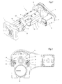
- Fig.1 to 5 is an extraction device 1 for the production of coffee presented, which finds the use in an automatic coffee machine. It has a brewing cylinder 2 with a cylinder part 20 and an axial with this joinable cylindrical attachment 22 on how will be explained in detail below.
- the tubular Brühzylinderteil 20 is attached to a carriage 3 and is with this in cooperation with a drive device 4 in its axial direction adjusted between predetermined positions back and forth and thereby on two guide rods 5, 6 out.
- the guide rods 5, 6 are with their ends in a respective holder 7, 8 attached.
- the drive device 4 comprises a force acting on the carriage 3 Drive spindle 9, which is rotatably mounted in the two holders 7, 8, and via a belt drive 11 with a drive motor 10, preferably a DC motor (DC motor) is in drive connection.
- the Axle of the drive spindle 9 is located in a longitudinal center plane of the extraction device 1, which extends between the two guide rods 5, 6.
- the adjustable in its axial direction brewing cylinder 2 are two relatively mutually adjustable piston 31, 32 assigned coaxially.
- the first, in the essential fixed piston 31 is formed in two parts. While a piston member 33 is fixedly secured in the holder 7, the other piston part 34 this slightly against axial movement and resiliently supported on this. Between the two piston parts 33, 34 is a compression spring 35th arranged.
- the two piston parts 33, 34 are at their periphery by an annular provided with a U-shaped cross-section seal 37 connected to each other, with their ends all around at both piston parts 33, 34 is attached.
- the compression spring 35 strives to the two piston parts 33, 34 apart while the seal 37 oblong to stretch.
- the second piston 32 is slidably guided in the brewing cylinder part 20. At the Circumference of this piston 32, an annular seal 38 is present.
- the second piston 32 protrudes with its piston rod 40 from the Brühzylinderteil 20 through a front-side brewing cylinder end portion 39 therethrough.
- the Piston rod 40 is at its end with a circumferential groove 42 having Head 41 preferably made of plastic, with which they are in a Mounted on the holder 8 holder 43 can be latched.
- the holder 43 has cooperating with the circumferential groove 42 rod-shaped spring elements 44, which are substantially tangential to the circumferential groove 42, and which aretufteddrückbar when snapped.
- Fig. 3 Position is the second piston 32 at the end portion 39 and the piston rod 40 is locked in the holder 43.
- the ejection process is shortened, and not least the Material saved for the shortened parts.
- the filling opening 24 having, not involved in the actual brewing additional part 22 made of a cheaper material such as plastic and in a simpler Processes are made as the stainless steel Brühzylinderteil, now made in the no side filler opening must become.
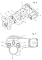
- Fig. 6 and Fig. 7 may be used for the introduction of the coffee powder the means for the end-side pressing of the cylinder part 20th with the additional part 22 by at least one spring 25, 26 also only one Concerns the cylinder part to be provided on the additional part.
- the cylindrical additional part 22 is on the filling of coffee powder one side with the brewing cylinder 2 in abutment, as shown in Fig. 3rd is illustrated, opposite it surrounds the piston 31, so that a chamber is formed. Then, the one not shown in detail Mill ground coffee through the filler opening 24 in the attachment 22 are brought into this chamber formed.
- the cylinder part 20 of the Piston 31 After completion of the brewing process, the cylinder part 20 of the Piston 31 retracted. After a certain distance will be the Piston 32 and by the assignment of parallel to the guide rods 5, 6 arranged slide bars 27 ', 28' and corresponding stops also the additional part 22 to the filling position, i. to the front of the Piston 31 (see Fig. 5) pulled. Once the cylinder part 20 the End position has reached the holder 8, the coffee cake is through ejected the piston 32.
Landscapes
- Engineering & Computer Science (AREA)
- Mechanical Engineering (AREA)
- Food Science & Technology (AREA)
- Apparatus For Making Beverages (AREA)
Abstract
Description
Die Erfindung betrifft eine Extraktionsvorrichtung zur Erzeugung von
Kaffee für eine Kaffeemaschine gemäss dem Oberbegriff des nachfolgenden
Anspruches 1.The invention relates to an extraction device for generating
Coffee for a coffee machine according to the preamble of the following
Eine Extraktionsvorrichtung ist in der EP-B-0 299 399 offenbart. Sie umfasst einen in Zusammenwirkung mit einer Antriebsvorrichtung entlang einer Längsführung zwischen vorbestimmten Stellungen hin und her verstellbaren Brühzylinder zur Aufnahme von Kaffeepulver sowie zwei zum Brühzylinder koaxiale, relativ zueinander verstellbare Kolben. Das Kaffeepulver wird durch eine seitliche Einfüllöffnung des Brühzylinders eingefüllt, wobei ein stirnseitig offenes Ende des Brühzylinders durch einen der beiden Kolben, den im wesentlichen feststehenden ersten Kolben, geschlossen gehalten wird. Beim Verstellen des Brühzylinders in der einen Richtung, über den ersten Kolben, begrenzt der erste Kolben zusammen mit dem zweiten, mit dem Brühzylinder mitbewegten Kolben stirnseitig eine Brühkammer und sorgt für das Verdichten des eingefüllten Kaffeepulvers. In dieser Stellung wird durch den einen Kolben brühendes Wasser in die Brühkammer und durch den verdichteten Kaffeepulver gepumpt und danach der erzeugte Kaffee durch den anderen Kolben zu einem Auslass der Kaffeemaschine befördert. Beim anschliessenden Verstellen des Brühzylinders in der anderen Richtung wird das verbrauchte Kaffeepulver durch den zweiten Kolben aus dem inzwischen vom ersten Kolben freigegebenen Brühzylinder-Ende ausgestossen.An extraction device is disclosed in EP-B-0 299 399. it includes one in cooperation with a drive device along a longitudinal guide between predetermined positions back and forth adjustable Brewing cylinder for receiving coffee powder and two for Brewing cylinder coaxial, relative to each other adjustable piston. The coffee powder is filled through a lateral filling opening of the brewing cylinder, wherein a frontally open end of the brewing cylinder by a the two pistons, the substantially fixed first piston, closed is held. When adjusting the brewing cylinder in one Direction, via the first piston, limited the first piston together with the second, with the brewing cylinder mitbewegten piston frontally a brewing chamber and ensures the compression of the filled coffee powder. In this position, brewing water through the one piston pumped into the brewing chamber and through the compacted coffee powder and then the coffee produced by the other piston to an outlet the coffee maker. During the subsequent adjustment of the brewing cylinder in the other direction is the used coffee powder through the second piston from the now released from the first piston Brewing cylinder end ejected.
Bei einer anderen gattungsmässigen Vorrichtung nach der Druckschrift US-A-5,275,089 sind ebenfalls zwei zum Brühzylinder verstellbare Kolben und ein eine Einfüllöffnung zum Einfüllen des Kaffeepulvers versehener Block vorgesehen. Innenseitig dieses zylinderförmigen Blocks ist eine Hülse und der eine Kolben längsbeweglich angeordnet. In der Einfüllposition liegt dieser Block am andern Hülsenteil mit dem anderen Kolben stirnseitig an, hingegen in der Ausstossposition sind sie voneinander getrennt. In der Brühposition kommt der beim Zusatzteil befindliche Kolben innerhalb des Zylinderteils zu liegen. Aufgrund der Notwendigkeit dieser Hülse in dem Block und ihrer Verschiebbarkeit wie auch des in ihr zugeordneten Kolbens ist ein komplizierter Aufbau dieser Extraktionsvorrichtung gegeben.In another generic device according to the document US-A-5,275,089 are also two adjustable to the brewing cylinder piston and a filler opening for filling the coffee powder Block provided. Inside of this cylindrical block is one Sleeve and arranged a piston longitudinally movable. In the filling position this block is on the other sleeve part with the other piston on the front side, whereas in the ejection position they are separated from each other. In the brewing position, the piston located at the additional part comes to lie within the cylinder part. Because of the need for this Sleeve in the block and its displaceability as well as the associated in her Kolben is a complex construction of this extraction device given.
Der vorliegenden Erfindung liegt die Aufgabe zugrunde, die an sich bewährte Extraktionsvorrichtung der eingangs genannten Art noch weiter zu verbessern und platzsparender zu gestalten.The present invention is based on the object, the proven per se Extraction device of the type mentioned even further improve and save space.
Diese Aufgabe ist erfindungsgemäss durch eine Extraktionsvorrichtung
mit den Merkmalen des Anspruches 1 gelöst.This object is achieved according to the invention by an extraction device
solved with the features of
Weitere bevorzugte Ausgestaltungen der erfindungsgemässen Extraktionsvorrichtung bilden den Gegenstand der abhängigen Ansprüche.Further preferred embodiments of the extraction device according to the invention form the subject of the dependent claims.
Mit der erfindungsgemässen Aufteilung in den Brühzylinder und in einen Zusatzteil, von denen der eine den eigentlichen, die Brühkammer umschliessenden und durch die Antriebsvorrichtung verstellbaren Brühzylinderteil bildet und der Zusatzteil an dem durch den ersten Kolben verschliessbaren Ende des Brühzylinders angeordnet und mit der Einfüllöffnung zum Einfüllen des Kaffeepulvers versehen ist, wobei die beiden Zylinderteile beim Verstellen des Brühzylinderteils in der einen Richtung stirnseitig aneinandergedrückt zusammenverstellt und beim Verstellen des Brühzylinderteils in der anderen Richtung voneinander getrennt werden können, so dass ein Axialspalt entsteht, durch welchen das verbrauchte Kaffeepulver herausfallen kann, kann die Länge des Brühzylinders sowie auch der zum Ausstossen des verbrauchten Kaffeepulvers notwendige Hub des zweiten Kolbens verkürzt werden, wodurch auch die Gesamtlänge der Extraktionsvorrichtung verkleinert wird. With the inventive division into the brewing cylinder and in a Additional part, of which the one the actual, the brewing chamber enclosing and adjustable by the drive device Brühzylinderteil forms and the additional part of the closable by the first piston End of the brewing cylinder arranged and with the filling opening provided for filling the coffee powder, wherein the two cylinder parts when adjusting the Brühzylinderteils in one direction pushed together at the end and adjusted when adjusting the Brühzylinderteils be separated in the other direction can, so that an axial gap arises, through which consumed Coffee powder can fall out, the length of the brewing cylinder as well also the necessary for the expulsion of the spent coffee powder hub be shortened of the second piston, whereby the total length of the Extraction device is reduced.
Ausserdem wird der Ausstossvorgang verkürzt, und nicht zuletzt auch das Material für die verkürzten Teile eingespart. Zudem kann der die Einfüllöffnung aufweisende, am eigentlichen Brühvorgang unbeteiligte Zusatzteil aus einem billigeren Material wie Kunststoff und in einem einfacheren Verfahren hergestellt werden als der aus rostfreiem Stahl bestehende Brühzylinder, in dem nun keine seitliche Einfüllöffnung angefertigt werden muss.In addition, the ejection process is shortened, and not least the Material saved for the shortened parts. In addition, the filling opening exhibiting, uninvolved in the actual brewing additional part from a cheaper material like plastic and in a simpler one Processes are made as the stainless steel Brewing cylinder in which now no lateral filling opening are made got to.
Die Erfindung wird nachfolgend anhand der Zeichnung näher erläutert. Es zeigen:
- Fig. 1
- ein Ausführungsbeispiel einer erfindungsgemässen Extraktionsvorrichtung für eine Kaffeemaschine in perspektivischer Darstellung;
- Fig. 2
- einen Schnitt nach Linie II - II in Fig. 3;
- Fig. 3
- im Längsschnitt die Extraktionsvorrichtung nach Fig. 1 in einer Ausgangsstellung;
- Fig. 4
- im Längsschnitt die Extraktionsvorrichtung nach Fig. 1 in einer Brühposition;
- Fig. 5
- im Längsschnitt die Extraktionsvorrichtung nach Fig. 1 in einer Ausstossposition,
- Fig. 6
- ein weiteres Ausführungsbeispiel einer erfindungsgemässen Extraktionsvorrichtung in perspektivischer Darstellung, und
- Fig. 7
- eine Ansicht des Ausführungsbeispiels nach Fig. 6, bei dem der zugehörige Halter weggelassen ist.
- Fig. 1
- an embodiment of an inventive extraction device for a coffee machine in perspective view;
- Fig. 2
- a section along line II - II in Fig. 3;
- Fig. 3
- in longitudinal section, the extraction device of Figure 1 in a starting position.
- Fig. 4
- in longitudinal section, the extraction device of Figure 1 in a brewing position.
- Fig. 5
- in a longitudinal section of the extraction device according to FIG. 1 in an ejection position, FIG.
- Fig. 6
- a further embodiment of an inventive extraction device in perspective view, and
- Fig. 7
- a view of the embodiment of FIG. 6, in which the associated holder is omitted.
In Fig.1 bis 5 ist eine Extraktionsvorrichtung 1 zur Erzeugung von Kaffee
dargestellt, die den Einsatz in einer automatischen Kaffeemaschine findet.
Sie weist einen Brühzylinder 2 mit einem Zylinderteil 20 und einen axial
mit diesem zusammenfügbaren zylindrischen Zusatzteil 22 auf, wie
weiter unten ausführlich erläutert wird. Einer dieser Teile, der rohrförmige
Brühzylinderteil 20 ist an einem Schlitten 3 befestigt und wird mit diesem
in Zusammenwirkung mit einer Antriebsvorrichtung 4 in seiner Achsrichtung
zwischen vorbestimmten Stellungen hin und her verstellt und dabei
auf zwei Führungsstangen 5, 6 geführt. Die Führungsstangen 5, 6 sind mit
ihren Enden in je einem Halter 7, 8 befestigt.In Fig.1 to 5 is an
Die Antriebsvorrichtung 4 umfasst eine auf den Schlitten 3 einwirkende
Antriebsspindel 9, die in den beiden Haltern 7, 8 drehbar gelagert ist, und
die über einen Riemenantrieb 11 mit einem Antriebsmotor 10, vorzugsweise
einem DC-Motor (Gleichstrommotor) in Antriebsverbindung steht. Die
Achse der Antriebsspindel 9 liegt in einer Längsmittelebene der Extraktionsvorrichtung
1, die zwischen den beiden Führungsstangen 5, 6 verläuft.The
In der in Fig. 3 gezeigten Stellung des Schlittens 3 liegt an einem stirnseitig
offenen Ende 21 des mit dem Schlitten 3 fest verbundenen Brühzylinderteils
20 der Zusatzteil 22 an, der mit einer seitlichen Einfüllöffnung 24
zum Einfüllen von Kaffeepulver in den Brühzylinder-Hohlraum versehen
ist. Der Zusatzteil 22 ist mit einem Führungsteil 23 verbunden und mit
diesem auf den Führungsstangen 5, 6 und lose auch über die Antriebsspindel
9 verschiebbar geführt (wird jedoch von der Antriebsspindel 9 nicht
angetrieben). Auf den Führungsteil 23 wirken zwei in den Führungsstangen
5, 6 integrierte Federn 25, 26 (vgl. Fig. 2) ein, die den Führungsteil 23
an je einen zu der jeweiligen Führungsstange 5, 6 radial gerichteten und
mit dieser beispielsweise verschraubten Anschlag 27, 28 drücken, und die
auch in dieser Stellung der Zusatzteil 22 und der Zylinderteil 20 axial zusammenfügen. In the position of the
Dem in seiner Achsrichtung verstellbaren Brühzylinder 2 sind zwei relativ
zueinander verstellbare Kolben 31, 32 koaxial zugeordnet. Der erste, im
wesentlichen feststehende Kolben 31 ist zweiteilig ausgebildet. Während
ein Kolbenteil 33 ortsfest im Halter 7 befestigt ist, ist der andere Kolbenteil
34 diesem gegenüber leicht axialbeweglich und an diesem federnd abgestützt.
Zwischen den beiden Kolbenteilen 33, 34 ist eine Druckfeder 35
angeordnet. Die beiden Kolbenteile 33, 34 sind an ihrem Umfang durch
eine ringförmige mit einem U-förmigen Querschnitt versehene Dichtung
37 miteinander verbunden, die mit ihren Enden rundum an beiden Kolbenteilen
33, 34 befestigt ist. Die Druckfeder 35 ist bestrebt, die beiden Kolbenteile
33, 34 auseinanderzudrücken und dabei die Dichtung 37 länglich
zu dehnen. Beim Andrücken des beweglichen Kolbenteils 34 an den ortsfesten
Kolbenteil 33, entgegen der Kraft der Druckfeder 35, wird die Dichtung
37 radial nach aussen gedrückt und somit in ihre dichtende Funktionsstellung
gebracht. Der erste Kolben 31 verschliesst hierbei das stirnseitig
offene Ende des Brühzylinders 2.The adjustable in its axial
Der zweite Kolben 32 ist verschiebbar im Brühzylinderteil 20 geführt. Am
Umfang dieses Kolbens 32 ist eine ringförmige Dichtung 38 vorhanden.
Der zweite Kolben 32 ragt mit seiner Kolbenstange 40 aus dem Brühzylinderteil
20 durch einen stirnseitigen Brühzylinder-Endteil 39 hindurch. Die
Kolbenstange 40 ist an ihrem Ende mit einem eine Umfangsnut 42 aufweisenden
Kopf 41 vorzugsweise aus Kunststoff versehen, mit dem sie in eine
am Halter 8 angebrachte Halterung 43 einrastbar ist. Die Halterung 43
weist mit der Umfangsnut 42 zusammenwirkende stabförmige Federelemente
44 auf, die im wesentlichen tangential zu der Umfangsnut 42 verlaufen,
und die beim Einrasten auseinanderdrückbar sind. Selbstverständlich
wäre auch eine andere Rastvorrichtung denkbar. In der in Fig. 3 gezeigten
Stellung befindet sich der zweite Kolben 32 beim Endteil 39 und
die Kolbenstange 40 ist in der Halterung 43 eingerastet.The
In der in Fig. 3 gezeigten Ausgangsstellung der Extraktionsvorrichtung 1
kann das gemahlene Kaffeepulver durch die seitliche, mit einer Kaffeemühle
verbundene Einfüllöffnung 24 in den Brühzylinder 2 eingefüllt
werden. Mit Vorteil können im Zusatzteil 22 zwei gegenüberliegende und
mit je einer Mühle korrespondierende seitliche Einfüllöffnungen 24 vorgesehen
sein.In the starting position of the
Nachdem eine definierte Portion von Kaffeepulver in den durch die beiden
Kolben 31, 32, den Brühzylinder 2 und den Zusatzteil 22 begrenzte Kammer
eingebracht worden ist, wird nun der Schlitten 3 mit dem Brühzylinderteil
20 mittels der Antriebsvorrichtung 4 in Pfeilrichtung A nach Fig. 3
in Bewegung gesetzt, wobei auch der am Zylinderteil 20 anliegende Zusatzteil
22 mit dem Führungsteil 23 mitbewegt und dabei von den in den
Führungsstangen 5, 6 integrierten Federn 25, 26 an den Brühzylinderteil
20 angedrückt verbleibt. Der Zylinderteil 20 sowie der Zusatzteil 22 werden
über den ersten Kolben 31 (unter Zusammendrückung seiner beiden
Kolbenteile 34, 33) in eine aus Fig. 4 ersichtliche Stellung geschoben.
Vom sich in Pfeilrichtung A bewegenden Brühzylinder 2 wird aber auch
der zweite Kolben 32 unter Ausrastung des Kopfes 41 aus der Halterung
43 mitgenommen und bis zu einem bestimmten Abstand gegen den feststehenden
ersten Kolben 31 hin bewegt. Dadurch wird die Kammer mit dem
Kaffeepulver bis zu einem vorbestimmten Mass verkleinert und das Kaffeepulver
zusammengepresst bzw. verdichtet.After a defined serving of coffee powder in by the two
In dieser in Fig. 4 dargestellten Brühposition kann der eigentliche Brühvorgang
durchgeführt werden, indem durch den einen Kolben (beispielsweise
durch Kanäle 32' des zweiten Kolbens 32) brühendes Wasser oder
Dampf in den durch Dichtungen 37, 38 abgedichteten Hohlraum und durch
das Kaffeepulver gepumpt und der erzeugte Kaffee durch den anderen
Kolben (beispielsweise durch Kanäle 31' des ersten Kolbens 31) zu einem
aus der Zeichnung nicht ersichtlichen Auslass der Kaffeemaschine befördert
wird.In this Brühposition shown in Fig. 4, the actual brewing
be performed by the one piston (for example
through channels 32 'of the second piston 32) brewing water or
Steam in the sealed by
Nach Beendigung des Brühvorganges wird mittels der Antriebsvorrichtung
4 der Schlitten 3 mit dem Brühzylinderteil 20 in der anderen Richtung
(Pfeilrichtung B nach Fig. 4) in Bewegung gesetzt. Der mit dem Führungsteil
23 verbundene Zusatzteil 22 bleibt anfänglich an den Brühzylinderteil
20 angedrückt und wird unter Wirkung der Feder 25, 26 mit diesem zurückbewegt,
bis der Führungsteil 23 an den mit den Führungsstangen 5, 6
verbundenen Anschlägen 26, 27 zur Anlage kommt. Nun wird der stehengebliebene,
mit der Einfüllöffnung 24 (bzw. den Einfüllöffnungen 24) versehene
Zusatzteil 22 von dem sich weiter mit dem Schlitten 3 in Pfeilrichtung
B bewegenden Brühzylinderteil 20 getrennt und dadurch ein Axialspalt
zwischen diesen beiden Teilen gebildet. Mit dem Brühzylinderteil 20
wird auch der zweite Kolben 32 in Pfeilrichtung B verstellt, bis der Kopf
41 wieder in die Halterung 43 einrastet. Da aber der Brühzylinderteil 20
mit dem Schlitten 3 weiter in Pfeilrichtung B zum Halter 8 hin bewegt
wird, bis eine Stirnfläche 46 des Brühzylinder-Endteils 39 an einer Gegenfläche
47 des in der Halterung 43 eingerasteten Kopfes 41 zur Anlage
kommt (vgl. Fig. 5), findet eine Relativbewegung zwischen dem zweiten
Kolben 32 und dem Brühzylinderteil 20 statt, und die verbrauchte Kaffeeportion
bzw. der Kaffeesatz wird durch den zweiten Kolben 32 aus dem
Brühzylinderteil 20 in den Axialspalt zwischen den Teilen 20, 22 ausgestossen
und fällt in einen darunterliegenden Auffangbehälter (in der Zeichnung
nicht dargestellt). After completion of the brewing process is by means of the
Mit der erfindungsgemässen Aufteilung des Brühzylinders 2 in den entlang
einer Längsführung (Führungsstangen 5, 6) geführten Zylinderteil 20 und
in den Zusatzteil 22, von denen der eine den eigentlichen, die Brühkammer
umschliessenden und durch die Antriebsvorrichtung 4 verstellbaren Brühzylinderteil
20 bildet und der Zusatzteil 22 mit der Einfüllöffnung 24 zum
Einfüllen des Kaffeepulvers versehen ist, wobei sie beim Verstellen des
Brühzylinderteils 20 in der einen Richtung A stirnseitig aneinandergedrückt
zusammenverstellt und beim Verstellen des Brühzylinderteils 20 in
der anderen Richtung B voneinander getrennt werden können, so dass ein
Axialspalt entsteht, durch welchen das verbrauchte Kaffeepulver ausgestossen
werden kann, kann die Länge des Brühzylinders 2 sowie auch der
zum Ausstossen des verbrauchten Kaffeepulvers notwendige Hub des
zweiten Kolbens 32 verkürzt werden, wodurch auch die Gesamtlänge der
Extraktionsvorrichtung 1 verkleinert wird.With the inventive division of the
Ausserdem wird der Ausstossvorgang verkürzt, und nicht zuletzt auch das
Material für die verkürzten Teile eingespart. Zudem kann der die Einfüllöffnung
24 aufweisende, am eigentlichen Brühvorgang unbeteiligte Zusatzteil
22 aus einem billigeren Material wie Kunststoff und in einem einfacheren
Verfahren hergestellt werden als der aus rostfreiem Stahl bestehende
Brühzylinderteil, in dem nun keine seitliche Einfüllöffnung angefertigt
werden muss.In addition, the ejection process is shortened, and not least the
Material saved for the shortened parts. In addition, the filling
Selbstverständlich wären auch andere Ausführungsformen der erfindungsgemässen Extraktionsvorrichtung durchaus denkbar. So könnte z.B. eine alternative Antriebsvorrichtung als in der Zeichnung dargestellt Anwendung finden. Of course, other embodiments of the inventive would be Extraction device quite conceivable. So could e.g. a Alternative drive device as shown in the drawing application Find.
Die Verwendung eines DC-Motors in der Art eines Schrittmotors ermöglicht eine sehr genaue und wiederholbare Positionseinstellung mit gleichbleibendem Anpressdruck, gleichbleibender Kaffeesatzportion, die ausgestossen werden muss, etc.The use of a DC motor in the manner of a stepper motor allows a very accurate and repeatable position setting with consistent Contact pressure, consistent coffee grounds portion that ejected must be, etc.
Gemäss Fig. 6 und Fig. 7 kann für das Einbringen des Kaffeepulvers anstelle
der Mittel zum stirnseitigen Aneinanderdrücken des Zylinderteils 20
mit dem Zusatzteil 22 durch mindestens eine Feder 25, 26 auch nur ein
Anliegen des Zylinderteils am Zusatzteil vorgesehen sein.According to Fig. 6 and Fig. 7 may be used for the introduction of the coffee powder
the means for the end-side pressing of the cylinder part 20th
with the
Die gleich ausgebildeten Teile wie diejenigen der Extraktionsvorrichtung gemäss Fig. 1 bis Fig. 5 sind mit denselben Bezugszeichen versehen und nachfolgend nicht mehr im Detail erläutert.The same parts as those of the extraction device According to Fig. 1 to Fig. 5 are provided with the same reference numerals and not explained in detail below.
Der zylinderförmige Zusatzteil 22 ist beim Einfüllen von Kaffeepulver auf
der einen Seite mit dem Brühzylinder 2 in Anschlag, wie dies in Fig. 3
veranschaulicht ist, gegenüberliegend umschliesst er den Kolben 31, so
dass eine Kammer gebildet ist. Sodann kann der von einer nicht näher gezeigten
Mühle gemahlene Kaffee durch die Einfüllöffnung 24 im Zusatzteil
22 in diese gebildete Kammer gebracht werden.The cylindrical
Anschliessend wird analog ,wie ebenfalls aus Fig. 3 ersichtlich ist, der Zylinderteil
20 und mit ihm der Kolben 32 weiter gegen den feststehenden
Kolben 31 hin geschoben, bis der Zylinderteil 20 diesen Kolben 31 umschliesst.
Gleichzeitig wird der Zusatzteil 22 in die gleiche Richtung mitbewegt,
bis er auf der Hinterseite des Kolbens zu liegen kommt. In dieser
Position wird das Kaffeepulver zu einem Kuchen gepresst und anschliessend
das heisse Wasser zur Erzeugung des Kaffees durch die Kolben gedrückt. Subsequently, analogously, as also shown in Fig. 3 it can be seen, the
Nach Beendigung des Brühvorganges wird vorerst der Zylinderteil 20 vom
Kolben 31 zurückgezogen. Nach einer gewissen Strecke wird auch der
Kolben 32 und durch die Zuordnung von parallel zu den Führungsstangen
5, 6 angeordneten Gleitstäben 27', 28' und entsprechenden Anschlägen
auch der Zusatzteil 22 bis zur Einfüllposition, d.h. an die Vorderseite des
Kolbens 31 (siehe dazu Fig. 5), gezogen. Sobald der Zylinderteil 20 die
Endposition bei der Halterung 8 erreicht hat, wird der Kaffeekuchen durch
den Kolben 32 ausgestossen.After completion of the brewing process, the
Damit ist eine einfache Lösung in Bezug auf die Verstellung des Zusatzteils
22 erzielt worden, ohne dass betriebliche Nachteile entstehen würden.This is a simple solution with respect to the adjustment of the
Claims (12)
Priority Applications (1)
| Application Number | Priority Date | Filing Date | Title |
|---|---|---|---|
| EP04405683A EP1535554A1 (en) | 2003-11-20 | 2004-11-08 | Extractiondevice of coffee for a coffee machine |
Applications Claiming Priority (3)
| Application Number | Priority Date | Filing Date | Title |
|---|---|---|---|
| EP03405829 | 2003-11-20 | ||
| EP03405829A EP1532903A1 (en) | 2003-11-20 | 2003-11-20 | Exractiondevice for making coffee for a coffee machine |
| EP04405683A EP1535554A1 (en) | 2003-11-20 | 2004-11-08 | Extractiondevice of coffee for a coffee machine |
Publications (1)
| Publication Number | Publication Date |
|---|---|
| EP1535554A1 true EP1535554A1 (en) | 2005-06-01 |
Family
ID=34466356
Family Applications (1)
| Application Number | Title | Priority Date | Filing Date |
|---|---|---|---|
| EP04405683A Withdrawn EP1535554A1 (en) | 2003-11-20 | 2004-11-08 | Extractiondevice of coffee for a coffee machine |
Country Status (1)
| Country | Link |
|---|---|
| EP (1) | EP1535554A1 (en) |
Cited By (7)
| Publication number | Priority date | Publication date | Assignee | Title |
|---|---|---|---|---|
| EP1774883A1 (en) * | 2005-10-14 | 2007-04-18 | Niro-Plan Ag | Coffee machine |
| WO2010100600A1 (en) * | 2009-03-06 | 2010-09-10 | Egro Coffee Systems Ag | Brewing piston for infusion preparation, brewing machine using the brewing piston |
| ITTO20090211A1 (en) * | 2009-03-19 | 2010-09-20 | Egro Coffee Systems Ag | INFUSION PISTON FOR INFUSION PREPARATION, INFUSION MACHINE THAT USES THE PISTON |
| CN101489448B (en) * | 2006-06-14 | 2012-06-27 | 瑞亚梵朵斯公司 | Brewing unit for automatic coffee machines |
| EP2561778A1 (en) * | 2011-08-22 | 2013-02-27 | FRANKE Kaffeemaschinen AG | Machine à café et groupe de distribution pour une machine à café |
| US10188238B2 (en) | 2014-03-11 | 2019-01-29 | Starbucks Corporation | Beverage production machines and methods with tamping assembly |
| IT201800004967A1 (en) * | 2018-04-27 | 2019-10-27 | SIMPLIFIED OPERATION COFFEE MACHINE |
Citations (4)
| Publication number | Priority date | Publication date | Assignee | Title |
|---|---|---|---|---|
| EP0299399B1 (en) | 1987-07-17 | 1993-12-01 | Sistar Sa | Device for brewing coffee |
| US5275089A (en) | 1990-10-25 | 1994-01-04 | Hermes Armellin | Automatic machine for the preparation of coffee infusions and process for operation |
| US6129006A (en) * | 1998-01-26 | 2000-10-10 | Finanara International B.V. | Coffee machine |
| US6634280B2 (en) * | 2000-05-31 | 2003-10-21 | Rancilio Macchine Per Caffe' S.P.A. | Coffee making machine |
-
2004
- 2004-11-08 EP EP04405683A patent/EP1535554A1/en not_active Withdrawn
Patent Citations (4)
| Publication number | Priority date | Publication date | Assignee | Title |
|---|---|---|---|---|
| EP0299399B1 (en) | 1987-07-17 | 1993-12-01 | Sistar Sa | Device for brewing coffee |
| US5275089A (en) | 1990-10-25 | 1994-01-04 | Hermes Armellin | Automatic machine for the preparation of coffee infusions and process for operation |
| US6129006A (en) * | 1998-01-26 | 2000-10-10 | Finanara International B.V. | Coffee machine |
| US6634280B2 (en) * | 2000-05-31 | 2003-10-21 | Rancilio Macchine Per Caffe' S.P.A. | Coffee making machine |
Cited By (12)
| Publication number | Priority date | Publication date | Assignee | Title |
|---|---|---|---|---|
| EP1774883A1 (en) * | 2005-10-14 | 2007-04-18 | Niro-Plan Ag | Coffee machine |
| CN101489448B (en) * | 2006-06-14 | 2012-06-27 | 瑞亚梵朵斯公司 | Brewing unit for automatic coffee machines |
| CN102631138A (en) * | 2006-06-14 | 2012-08-15 | 瑞亚梵朵斯公司 | Brewing unit for automatic coffee machines |
| WO2010100600A1 (en) * | 2009-03-06 | 2010-09-10 | Egro Coffee Systems Ag | Brewing piston for infusion preparation, brewing machine using the brewing piston |
| CN102438488A (en) * | 2009-03-06 | 2012-05-02 | 埃格罗咖啡系统公司 | Brewing piston for infusion preparation, brewing machine using the brewing piston |
| US8414944B2 (en) | 2009-03-06 | 2013-04-09 | Egro Coffee Systems Ag | Brewing machine with brewing piston for infusion preparation and method of using same |
| CN102438488B (en) * | 2009-03-06 | 2015-05-27 | 兰奇利集团股份公司 | Brewing piston for infusion preparation, brewing machine using the brewing piston |
| ITTO20090211A1 (en) * | 2009-03-19 | 2010-09-20 | Egro Coffee Systems Ag | INFUSION PISTON FOR INFUSION PREPARATION, INFUSION MACHINE THAT USES THE PISTON |
| EP2561778A1 (en) * | 2011-08-22 | 2013-02-27 | FRANKE Kaffeemaschinen AG | Machine à café et groupe de distribution pour une machine à café |
| US9214017B2 (en) | 2011-08-22 | 2015-12-15 | Franke Kaffeemaschinen Ag | Coffee machine and brewing assembly for a coffee machine |
| US10188238B2 (en) | 2014-03-11 | 2019-01-29 | Starbucks Corporation | Beverage production machines and methods with tamping assembly |
| IT201800004967A1 (en) * | 2018-04-27 | 2019-10-27 | SIMPLIFIED OPERATION COFFEE MACHINE |
Similar Documents
| Publication | Publication Date | Title |
|---|---|---|
| EP1532903A1 (en) | Exractiondevice for making coffee for a coffee machine | |
| EP0237475B1 (en) | Piston and cylinder unit for a coffee machine, and its operating method | |
| DE2158173C3 (en) | Machine for the preparation of infusions, especially express coffee | |
| EP2055214A1 (en) | Brewing device for a coffee machine | |
| WO2007017455A1 (en) | Apparatus for extracting an extraction substance, which is contained in a capsule, with a liquid extraction means | |
| DE60101273T2 (en) | COFFEE MACHINE | |
| EP1912542A1 (en) | Apparatus for extracting an extraction substance, which is contained in a capsule, with a liquid extraction means | |
| DE202005018607U1 (en) | Brewing unit for a coffee machine | |
| EP0937443A2 (en) | Device for introducing an intraocular lens | |
| EP1535554A1 (en) | Extractiondevice of coffee for a coffee machine | |
| EP2451324B1 (en) | Brewing unit, in particular for a coffee maker | |
| EP3297503B1 (en) | Apparatus for preparing coffee in an automatic coffee machine | |
| DE10222132B4 (en) | Multiple helical, one-piece pressed gear and method and apparatus for its production | |
| EP3060086A1 (en) | Modular brewing unit for a coffee machine | |
| EP0528759B1 (en) | Driving device for a brewing unit in a coffee machine | |
| DE10242283B4 (en) | Apparatus and method for pressing a bearing mat to a monolith | |
| EP2581002B1 (en) | Brewing assembly | |
| DE60007022T2 (en) | Machine for preparing espresso coffee with hydraulic device for compacting the ground coffee | |
| EP3695758B1 (en) | Brew unit of a coffee machine, coffee machine and method of brewing coffee | |
| DE60101261T2 (en) | Infusion device for coffee machine | |
| EP2561779A1 (en) | Brewing device for a coffee machine | |
| EP2512705A1 (en) | Device for setting fastening elements | |
| DE19716813B4 (en) | Taumelgelenkbeschlag for motor vehicle seats, in particular for backrest joints, and method for its preparation | |
| DE3049276C2 (en) | Briquetting press | |
| DE537675C (en) | Method and device for increasing the pressing time in presses with crank or toggle lever drive |
Legal Events
| Date | Code | Title | Description |
|---|---|---|---|
| PUAI | Public reference made under article 153(3) epc to a published international application that has entered the european phase |
Free format text: ORIGINAL CODE: 0009012 |
|
| AK | Designated contracting states |
Kind code of ref document: A1 Designated state(s): AT BE BG CH CY CZ DE DK EE ES FI FR GB GR HU IE IS IT LI LU MC NL PL PT RO SE SI SK TR |
|
| AX | Request for extension of the european patent |
Extension state: AL HR LT LV MK YU |
|
| 17P | Request for examination filed |
Effective date: 20051121 |
|
| AKX | Designation fees paid |
Designated state(s): AT BE BG CH CY CZ DE DK EE ES FI FR GB GR HU IE IS IT LI LU MC NL PL PT RO SE SI SK TR |
|
| 17Q | First examination report despatched |
Effective date: 20070221 |
|
| STAA | Information on the status of an ep patent application or granted ep patent |
Free format text: STATUS: THE APPLICATION IS DEEMED TO BE WITHDRAWN |
|
| 18D | Application deemed to be withdrawn |
Effective date: 20070703 |