EP1533866A1 - Adaptive phased array antenna with digital beam forming - Google Patents
Adaptive phased array antenna with digital beam forming Download PDFInfo
- Publication number
- EP1533866A1 EP1533866A1 EP04104960A EP04104960A EP1533866A1 EP 1533866 A1 EP1533866 A1 EP 1533866A1 EP 04104960 A EP04104960 A EP 04104960A EP 04104960 A EP04104960 A EP 04104960A EP 1533866 A1 EP1533866 A1 EP 1533866A1
- Authority
- EP
- European Patent Office
- Prior art keywords
- antenna
- signal
- sub
- cluster
- signals
- Prior art date
- Legal status (The legal status is an assumption and is not a legal conclusion. Google has not performed a legal analysis and makes no representation as to the accuracy of the status listed.)
- Granted
Links
Images


Classifications
-
- G—PHYSICS
- G01—MEASURING; TESTING
- G01S—RADIO DIRECTION-FINDING; RADIO NAVIGATION; DETERMINING DISTANCE OR VELOCITY BY USE OF RADIO WAVES; LOCATING OR PRESENCE-DETECTING BY USE OF THE REFLECTION OR RERADIATION OF RADIO WAVES; ANALOGOUS ARRANGEMENTS USING OTHER WAVES
- G01S13/00—Systems using the reflection or reradiation of radio waves, e.g. radar systems; Analogous systems using reflection or reradiation of waves whose nature or wavelength is irrelevant or unspecified
- G01S13/02—Systems using reflection of radio waves, e.g. primary radar systems; Analogous systems
- G01S13/06—Systems determining position data of a target
- G01S13/42—Simultaneous measurement of distance and other co-ordinates
- G01S13/426—Scanning radar, e.g. 3D radar
-
- G—PHYSICS
- G01—MEASURING; TESTING
- G01S—RADIO DIRECTION-FINDING; RADIO NAVIGATION; DETERMINING DISTANCE OR VELOCITY BY USE OF RADIO WAVES; LOCATING OR PRESENCE-DETECTING BY USE OF THE REFLECTION OR RERADIATION OF RADIO WAVES; ANALOGOUS ARRANGEMENTS USING OTHER WAVES
- G01S13/00—Systems using the reflection or reradiation of radio waves, e.g. radar systems; Analogous systems using reflection or reradiation of waves whose nature or wavelength is irrelevant or unspecified
- G01S13/02—Systems using reflection of radio waves, e.g. primary radar systems; Analogous systems
- G01S13/06—Systems determining position data of a target
- G01S13/46—Indirect determination of position data
- G01S13/48—Indirect determination of position data using multiple beams at emission or reception
-
- H—ELECTRICITY
- H01—ELECTRIC ELEMENTS
- H01Q—ANTENNAS, i.e. RADIO AERIALS
- H01Q25/00—Antennas or antenna systems providing at least two radiating patterns
-
- G—PHYSICS
- G01—MEASURING; TESTING
- G01S—RADIO DIRECTION-FINDING; RADIO NAVIGATION; DETERMINING DISTANCE OR VELOCITY BY USE OF RADIO WAVES; LOCATING OR PRESENCE-DETECTING BY USE OF THE REFLECTION OR RERADIATION OF RADIO WAVES; ANALOGOUS ARRANGEMENTS USING OTHER WAVES
- G01S13/00—Systems using the reflection or reradiation of radio waves, e.g. radar systems; Analogous systems using reflection or reradiation of waves whose nature or wavelength is irrelevant or unspecified
- G01S13/02—Systems using reflection of radio waves, e.g. primary radar systems; Analogous systems
- G01S13/06—Systems determining position data of a target
- G01S13/08—Systems for measuring distance only
- G01S13/10—Systems for measuring distance only using transmission of interrupted, pulse modulated waves
- G01S13/24—Systems for measuring distance only using transmission of interrupted, pulse modulated waves using frequency agility of carrier wave
Definitions
- the present invention relates to the realization of an antenna adaptive multibeam beamforming by calculation, cut off in subnets.
- This antenna makes it possible in particular to form bundles devoid of lobes of parasitic networks.
- This device applies particularly in the fight against the jamming of radars.
- These adaptive FFC antennas consist of a large number of transmit / receive modules still called T / R modules.
- the T / R modules are combined together to form subnets.
- Each subnet behaves like a basic antenna having its own plan and phase center.
- the formation of a beam is done by combining the signals from the subnetworks which constitute the global antenna.
- To constitute the signal corresponding to a beam given each signal coming from a subnet is assigned a gain and of a determined phase shift. Then all the signals thus corrected are are.
- the values of the gain and phase weightings of each subnetwork are determined by known methods, coming from the field of adaptive anti-jamming, the subnetwork structure being developed at anti-jamming purposes.
- the overall orientation of the beam bundle of a multibeam antenna is realized while playing on the phase relative signals from the T / R modules. By doing so, we modify the overall orientation of the phase plan of the antenna.
- Phase plans of the subnetworks are in most cases not oriented in the direction of the beam to form.
- the only accessible way to form a beam in a given direction is to adjust the phase of the signal from each sub-network to obtain, by recombination, the desired beam.
- the subnets therefore constitute elementary antennas that present by construction distant phase centers one of the other.
- the distance between their phase centers is large compared to the wave length.
- the phasing of signals from different sub-networks leads, during the formation of the beam, the appearance parasitic lobes.
- These parasitic lobes or lobes of networks are the reproduction of the desired beam lobe, according to determined directions by the distance separating the phase centers from the subnetworks.
- the current FFC antennas form beams that have an unwanted spatial periodicity.
- An object of the invention is in particular to overcome the disadvantages cited.
- the invention relates to an adaptive FFC antenna allowing the simultaneous constitution of several beams.
- the antenna according to the invention has particular characteristic to present for each sub-network phase planes oriented perpendicular to the direction of each of the beams.
- the antenna according to the invention comprises in particular T / R modules clustered. Clusters are themselves assembled in groups to form subnets and the combination of subnets forms the beams.
- the overall direction of the plan phase of a multibeam antenna is performed, as for a conventional single-beam electronic scanning antenna, playing on the relative phase of the signals from the T / R modules.
- the antenna is considered to retain constant orientation and that a zero phase shift is applied to the T / R modules.
- Figure 1 illustrates in graphic form the disadvantages induced by the embodiment of current adaptive FFC antennas.
- This figure represents in a single plane and for a given beam, oriented in an axis taken as a reference, the emission and reception diagrams.
- the emission diagram 11 being necessarily broad, the energy susceptible to be received by beam 12 is not significantly different from that likely to be received by the lobes of networks 13.
- the appearance of a jamming signal in one of these lobes of networks will affect very importantly the detection of possible echoes by the beam corresponding.
- lattice lobes have an angular repetitivity ⁇ which depends on the ratio , ratio of the distance of the phase centers of the sub-networks to the wavelength of the signal.
- Figure 2 presents in a pictorial way the structural origin of the appearance of the network lobes phenomenon previously described in the case of a single beam.
- subnets are represented in this figure as being contiguous and of the same size.
- the phase plans of the subnetworks are oriented in a fixed direction, identical for all beams formed. Different structures, for example with size networks different and with some overlap, are obviously possible.
- the line 21 shows the phase plan of the global antenna and the angle of misalignment of the beam to be formed, the direction of which is materialized by the 22.
- the straight line 23 represents the ideal phase plane to be get the desired misalignment. This ideal plan can only be achieved by adjusting the phase shift at the T / R modules, which can not be, as this has been said previously, carried out simultaneously for each of beams to form.
- each step of curve 24 represents the phase plan of the sub-network corresponding.
- the combination of signals is represented in the figure by the dotted arrows 27.
- the formation of the desired beam 22 is accompanied also that of the network lobes 25 whose appearance is linked to the discontinuities of curve 24.
- the reception pattern G n associated with a beam F n has an expression of the following form:
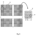
- FIG. 3 illustrates the principle of organizing an FFC antenna adaptive device according to the invention.
- the T / R modules are only more grouped directly into subnets but are first combined by small groups to form basic units 31 called clusters.
- a cluster consists of a group of T / R modules connected together to others through microwave combiner circuits. As on the FIG. 3, the clusters constituting the antenna are for example disjoint and their juxtaposition reconstitutes the entire antenna.
- the cluster represents the basic element of an adaptive FFC antenna according to the invention.
- the number Q of T / R modules used in composing a cluster is any and can, for example, vary from one cluster to another in a same antenna.
- FIG. consisting of an assembly of identical clusters each formed of sixteen T / R modules 32.
- the T / R modules are spaced apart from one another distance close to the half-wavelength of the signal.
- Each T / R module is also equipped with an amplitude and phase control, which allows guide the overall phase plan of the antenna.
- FIG. 4 illustrates the internal structure of a cluster 31 according to the invention.
- the output of each T / R module 32 is distributed in parallel on the inputs of several independent microwave combiners.
- a combiner C 0 , 41 realizes the sum of the signals 42 from the different T / R modules. It thus produces a signal S 0 , 43, corresponding to the reception channel relative to the antenna beam F 0 , perpendicular to the phase plane of the antenna.
- the other combiners 44 perform the synthesis of corrective signals c fn , 45, corresponding to a weighted sum of the signals from the different T / R modules. This weighting is performed in amplitude and phase.
- each antenna beam formed It is specific to each antenna beam formed and makes it possible to obtain for each T / R module the signal corresponding to the difference existing between the signal actually received by the T / R module and the theoretical signal that would be received if the The phase of the T / R module was oriented perpendicular to the direction of the beam. For a given real phase plane, this difference will be zero only for the signal received from a direction perpendicular to the phase plane of the module T / R, this direction corresponding for example to the antenna beam F 0 .
- a cluster therefore comprises a summing circuit making it possible to constitute the beam F 0 , for which the difference between the real signal and the theoretical signal is zero. It also includes as many combiner circuits as there are other antenna beams to form. It thus has an output 43 corresponding to the signal relating to the beam F 0 . and as many corrective outputs 45 as beams to form.
- FIG. 5 illustrates, in a pictorial manner, the imperfections related to subnetting, and the manner in which it is possible to correct these imperfections thanks to the cluster structure of the antenna according to the invention.
- This illustration represents a partial enlarged view of the illustration of an antenna composed of sub-networks as shown in FIG. 2.
- the bearings 51 represent the phase planes of the different sub-networks that make up the antenna.
- the line segments 52 include the orientation of the same phase planes for forming a beam without grating lobes in a given direction. This direction is symbolized by the arrows 52. Since the orientation of the overall phase plane of the antenna is represented by the line 23, it can be seen that the positioning of the phase planes of the different sub-networks represents only an approximation.
- This positioning is achieved by applying to each signal from a T / R modulates a same phase shift ⁇ re represented by the vectors 53. The signals thus phase shifted are then summed to form the receiving path of the considered subnet. The resulting approximation is responsible for the appearance of lattice lobes.
- the antenna according to the invention makes it possible to correct the imperfections of the signal obtained.
- the cluster provides a correction signal developed by performing a weighted sum of the signals from the T / R modules that compose it.
- an elementary corrective signal is thus obtained that makes it possible to compensate for the difference ⁇ existing between the phase shift actually applied to the modulating T / R and the theoretical phase shift enabling a beam devoid of lobes to be obtained. networks.
- the correction signals are illustrated in FIG. 5 in the form of the vectors 56.
- the elementary corrective signals corresponding to the same beam F i are summed so as to constitute a corrective signal sum c Fn .
- information is available to form beams without network lobes.
- FIG. 6 schematically shows an example of complete structure of the antenna according to the invention.
- the outputs 34 of the T / R modules are distributed over different clusters 31.
- the outputs 43 of several clusters forming the same sub-network are applied to the inputs of a summing circuit 61 so as to produce, from the signals s 0.i from each cluster of the sub-network, a signal 62 corresponding to the signal S 0.r received by the sub-network r in the direction of the beam F 0 perpendicular to the phase plane of the antenna.
- the outputs 45 of all clusters corresponding to the same beam are applied to the inputs of a summing circuit 63 so as to obtain, from the signals c nk from each cluster, a corrector signal C n , 64
- This signal makes it possible to reconstitute the signal received by the antenna in the direction of the beam F n .
- the structure therefore has as many summing circuits as there are sub-networks and beams to form.
- the outputs of the different summing circuits are then applied to receivers 65, integrated or not to the antenna, which perform the demodulation and digitization of the signals.
- the number of receivers required here is advantageously equal to the sum of the number of sub-networks constituting the antenna and the number of beams formed minus one.
- the beamforming by the calculation is here performed almost conventionally by calculating the matrix W correction coefficients to be applied to the signal from each sub-network.
- ⁇ 0 corresponds to the direction vector which defines the overall phase shift to be applied to the signals coming from the different sub-networks.
- ⁇ 0 characterizing a conventional sub-network antenna, in that it has as many lines as sub-networks and an additional line relating to the correction. corresponding to the beam considered.
- R x represents the covariance matrix of the signal composed of the signals coming from the different sub-networks and the correction signal relating to the beam considered.
- R x -1 has one more line than in the case of a conventional sub-array antenna. In the absence of jammers the matrix R x -1 corresponds to a unit matrix. It therefore appears possible to produce, from the antenna according to the invention, a multibeam antenna whose beams are advantageously devoid of lattice lobes. Such an antenna has the advantage of requiring only a reduced number of additional receivers compared to a conventional multibeam antenna having the same number of sub-networks.
- the number of additional receivers is for example equal to N-1.
- the formation of the beam F 0 is performed by summing the signals S 0.r from the different sub-networks. The sum of the different signals S 0.r constitutes the global signal S 0 .
- the formation of the other beams F n is carried out by performing the correction of the signal S 0 corresponding to the beam F 0 by the corrector signal C n relating to the beam F n .
Landscapes
- Engineering & Computer Science (AREA)
- Radar, Positioning & Navigation (AREA)
- Remote Sensing (AREA)
- Computer Networks & Wireless Communication (AREA)
- Physics & Mathematics (AREA)
- General Physics & Mathematics (AREA)
- Variable-Direction Aerials And Aerial Arrays (AREA)
Abstract
Description
La présente invention concerne la réalisation d'une antenne adaptative multifaisceaux, à formation de faisceaux par le calcul, découpée en sous-réseaux. Cette antenne permet notamment de former des faisceaux dépourvus de lobes de réseaux parasites. Ce dispositif s'applique notamment à la lutte contre le brouillage des radars.The present invention relates to the realization of an antenna adaptive multibeam beamforming by calculation, cut off in subnets. This antenna makes it possible in particular to form bundles devoid of lobes of parasitic networks. This device applies particularly in the fight against the jamming of radars.
Les antennes actuelles qui mettent en oeuvre la formation adaptative de faisceaux par le calcul, ou FFC adaptative, présentent des inconvénients importants à l'émission et à la réception. Les inconvénients rencontrés sont notamment liés à leur structure.Current antennas that implement adaptive training of beams by calculation, or adaptive FFC, have disadvantages important to the show and the reception. The disadvantages encountered are in particular related to their structure.
Ces antennes à FFC adaptative sont constituées d'un grand nombre de modules d'émission / réception encore appelés T/R modules. Les T/R modules sont combinés entre eux pour former des sous-réseaux. Chaque sous-réseau se comporte comme une antenne élémentaire ayant ses propres plan et centre de phase.These adaptive FFC antennas consist of a large number of transmit / receive modules still called T / R modules. The T / R modules are combined together to form subnets. Each subnet behaves like a basic antenna having its own plan and phase center.
En ce qui concerne la réception d'un signal, la formation d'un faisceau se fait en combinant les signaux issus des sous-réseaux qui constituent l'antenne globale. Pour constituer le signal correspondant à un faisceau donné chaque signal issu d'un sous-réseau est affecté d'un gain et d'un déphasage déterminé. Puis tous les signaux ainsi corrigés sont sommés. Les valeurs des pondérations en gain et en phase de chaque sous-réseau sont déterminées par des procédés connus, issus du domaine de l'antibrouillage adaptatif, la structure en sous-réseaux étant développée à des fins d'antibrouillage.With regard to the reception of a signal, the formation of a beam is done by combining the signals from the subnetworks which constitute the global antenna. To constitute the signal corresponding to a beam given each signal coming from a subnet is assigned a gain and of a determined phase shift. Then all the signals thus corrected are are. The values of the gain and phase weightings of each subnetwork are determined by known methods, coming from the field of adaptive anti-jamming, the subnetwork structure being developed at anti-jamming purposes.
Comme dans le cas d'une antenne à balayage électronique mono faisceau classique, l'orientation globale de la grappe de faisceau d'une antenne multifaisceaux est réalisée quant à elle en jouant sur la phase relative des signaux issus des T/R modules. En agissant ainsi, on modifie l'orientation globale du plan de phase de l'antenne. As in the case of a mono electronic scanning antenna conventional beam, the overall orientation of the beam bundle of a multibeam antenna is realized while playing on the phase relative signals from the T / R modules. By doing so, we modify the overall orientation of the phase plan of the antenna.
L'association des T/R modules en sous-réseaux telle qu'elle est
réalisée, revient à effectuer une décomposition de l'antenne globale en
antennes élémentaires de faibles dimensions. Chaque antenne élémentaire
se comporte comme une source unitaire avec ses propres plan et centre de
phase Le lobe d'antenne global est obtenu en recombinant les lobes des
antennes élémentaires.
Cette décomposition en antennes élémentaires présente cependant des
inconvénients :
- La dimension de ces antennes élémentaires étant faible par rapport à l'antenne globale, celles-ci présentent donc à l'émission aussi bien qu'à la réception un lobe dont le diagramme est plus large que celui d'une antenne de grande dimension classique.
- La combinaison de ces lobes entraíne par ailleurs la présence au
niveau de l'antenne globale de lobes secondaires plus importants que ceux
d'une antenne mono faisceau.
La structure en sous-réseaux des antennes à FFC adaptative actuelles a donc pour effet de rendre celles-ci globalement moins performantes que les antennes à balayage électronique classiques notamment au niveau des lobes secondaires.
This decomposition into elementary antennas, however, has disadvantages:
- Since the size of these elementary antennas is small relative to the global antenna, these antennas therefore have on both transmit and receive a lobe whose pattern is wider than that of a conventional large-size antenna. .
- The combination of these lobes also causes the presence at the level of the global antenna of secondary lobes greater than those of a single beam antenna.
The sub-network structure of current adaptive FFC antennas therefore has the effect of making them generally less efficient than conventional electronic scanning antennas, particularly at the level of the secondary lobes.
Des études menées par ailleurs montrent que pour pouvoir reconstituer de façon correcte un faisceau d'antenne à partir de sous-ensembles dont les plans de phase ne sont pas orientés dans la direction du faisceau, il faut que la distance entre les centres de phase des différents sous-ensembles soit inférieure à la demi longueur d'onde du signal. Or, dans le cas des sous-réseaux constituant une antenne à FFC, cette condition de distance n'est pas satisfaite et le faisceau formé est accompagné de lobes parasites dont la périodicité spatiale est fonction de l'espacement des centres de phase des différents sous-réseaux.Studies elsewhere show that in order to be able to correctly reconstruct an antenna beam from subsets whose phase plans are not oriented in the direction of the beam, it is necessary that the distance between the phase centers of the different subsets is less than the half wavelength of the signal. Now, in In the case of the sub-networks constituting a FFC antenna, this condition of distance is not satisfied and the beam formed is accompanied by lobes parasites whose spatial periodicity is a function of the spacing of phase centers of different subnets.
En revanche, dans le cas particulier où tous les sous-ensembles présentent un plan de phase orienté dans la direction du faisceau, il n'y a pas formation de lobes de réseaux.On the other hand, in the particular case where all subsets present a phase plane oriented in the beam direction, there is no network lobe formation.
On conçoit aisément que pour une antenne multifaisceaux à sous-réseaux, la condition d'orientation ci-dessus ne peut être réalisée, dans le meilleur des cas, que pour un seul faisceau. Les plans de phase des sous-réseaux ne sont pas, dans la plupart des cas, orientés dans la direction du faisceau à former. La seule façon accessible de former un faisceau dans une direction donnée est d'ajuster la phase du signal issu de chaque sous-réseau pour obtenir, par recombinaison, le faisceau voulu.It is easy to see that for a multibeam antenna with sub-networks, the above orientation condition can not be achieved in the best case, only for a single beam. Phase plans of the subnetworks are in most cases not oriented in the direction of the beam to form. The only accessible way to form a beam in a given direction is to adjust the phase of the signal from each sub-network to obtain, by recombination, the desired beam.
Les sous-réseaux constituent donc des antennes élémentaires qui présentent par construction des centres de phase éloignés les uns des autres. La distance entre leurs centres de phase est grande par rapport à la longueur d'onde. De ce fait, la mise en phase des signaux issus des différents sous-réseaux entraíne, lors de la formation du faisceau, l'apparition de lobes parasites. Ces lobes parasites ou lobes de réseaux sont la reproduction du lobe de faisceau désiré, suivant des directions déterminées par la distance séparant les centres de phase des sous-réseaux. Ainsi, du fait de leur organisation en sous-réseaux, les antennes à FFC actuelles forment des faisceaux qui présentent une périodicité spatiale non voulue.The subnets therefore constitute elementary antennas that present by construction distant phase centers one of the other. The distance between their phase centers is large compared to the wave length. As a result, the phasing of signals from different sub-networks leads, during the formation of the beam, the appearance parasitic lobes. These parasitic lobes or lobes of networks are the reproduction of the desired beam lobe, according to determined directions by the distance separating the phase centers from the subnetworks. Thus, makes their organization into sub-networks, the current FFC antennas form beams that have an unwanted spatial periodicity.
La présence de ces lobes de réseaux a pour conséquence de rendre les antennes actuelles vulnérables au brouillage reçu dans la direction des lobes de réseaux. L'élimination d'un brouilleur pénétrant par un lobe de réseau s'accompagne d'un affaiblissement important du signal dans la direction du faisceau.The presence of these lobes of networks has the consequence of make existing antennas vulnerable to interference received in the direction network lobes. The elimination of a penetrating jammer by a lobe of network is accompanied by a significant weakening of the signal in the direction of the beam.
D'autres inconvénients sont par ailleurs liés à la nécessité qu'ont les dispositifs actuels équipés d'antennes à FFC d'émettre avec un diagramme de rayonnement élargi. Ce diagramme élargi est nécessaire pour permettre la réception d'un signal dans toutes les directions pointées par les faisceaux formés simultanément. Ce diagramme, plus large que celui d'une antenne classique, présente l'inconvénient d'entraíner une perte de sélectivité spatiale à l'émission. La sélectivité n'est plus alors réalisée que par le lobe du faisceau de réception, qui présente, comme cela a été dit précédemment, des lobes secondaires de mauvaise qualité.Other disadvantages are related to the need for current devices equipped with FFC antennas to emit with a diagram expanded radiation. This expanded diagram is necessary to allow receiving a signal in all directions pointed by the beams formed simultaneously. This diagram, wider than that of an antenna conventional, has the disadvantage of causing a loss of selectivity space on the show. Selectivity is then only achieved by the lobe of the receiving beam, which presents, as has been said previously, secondary lobes of poor quality.
Un but de l'invention est notamment de pallier les inconvénients cités. A cet effet l'invention a pour objet une antenne à FFC adaptative permettant la constitution simultanée de plusieurs faisceaux. L'antenne selon l'invention a notamment pour caractéristique de présenter pour chaque sous-réseau des plans de phase orientés perpendiculairement à la direction de chacun des faisceaux.An object of the invention is in particular to overcome the disadvantages cited. For this purpose the invention relates to an adaptive FFC antenna allowing the simultaneous constitution of several beams. The antenna according to the invention has particular characteristic to present for each sub-network phase planes oriented perpendicular to the direction of each of the beams.
L'antenne selon l'invention comporte notamment des T/R modules assemblés en clusters. Les clusters sont eux-mêmes assemblés par groupes pour former des sous-réseaux et la combinaison des sous-réseaux forme les faisceaux.The antenna according to the invention comprises in particular T / R modules clustered. Clusters are themselves assembled in groups to form subnets and the combination of subnets forms the beams.
Chaque cluster comporte une voie de sommation et plusieurs
voies de correction. La voie de sommation effectue la somme de signaux
issus des différents T/R modules associés au cluster. Le signal obtenu
correspond à celui reçu dans la direction du faisceau F0 perpendiculaire au
plan de phase de l'antenne. Les voies de correction affectent à chaque signal
issu d'un T/R module une correction en phase et en amplitude de façon à
obtenir un signal représentatif de la différence vectorielle existant entre le
signal reçu dans la direction d'un faisceau Fn et celui reçu dans la direction
F0. Chaque cluster comporte autant de voies de correction que l'antenne
comporte de faisceaux
Comme il a été rappelé précédemment, l'orientation globale du plan de phase d'une antenne multifaisceaux est réalisée, comme pour une antenne à balayage électronique mono faisceau classique, en jouant sur la phase relative des signaux issus des T/R modules. Pour des raisons de clarté, dans la suite de la description on considère que l'antenne garde une orientation constante et qu'on applique un déphasage nul aux T/R modules.As noted above, the overall direction of the plan phase of a multibeam antenna is performed, as for a conventional single-beam electronic scanning antenna, playing on the relative phase of the signals from the T / R modules. For reasons of clarity, in the remainder of the description the antenna is considered to retain constant orientation and that a zero phase shift is applied to the T / R modules.
La figure 1 illustre sous forme d'un graphique les inconvénients induits
par le mode de réalisation des antennes à FFC adaptative actuelles. Cette
figure représente dans un seul plan et pour un faisceau donné, orienté dans
un axe pris comme référence, les diagrammes d'émission et de réception. Le
diagramme d'émission 11 étant nécessairement large, l'énergie susceptible
d'être reçu par le faisceau 12 n'est pas assez significativement différente de
celle susceptible d'être reçue par les lobes de réseaux 13. D'autre part,
l'apparition d'un signal brouilleur dans un de ces lobes de réseaux, affectera
de manière très importante la détection d'éventuels échos par le faisceau
correspondant.Figure 1 illustrates in graphic form the disadvantages induced
by the embodiment of current adaptive FFC antennas. This
figure represents in a single plane and for a given beam, oriented in
an axis taken as a reference, the emission and reception diagrams. The
emission diagram 11 being necessarily broad, the energy susceptible
to be received by
Ces lobes de réseaux ont une répétitivité angulaire α qui dépend
du rapport ![]()
![]()
La présence de ces lobes de réseaux a pour conséquence de générer une ambiguïté sur la position angulaire d'un éventuel écho reçu par un radar équipé d'une antenne à FFC adaptative actuelle. Elle rend également le radar sensible au brouillage par les lobes de réseaux. The presence of these lobes of networks has the consequence of ambiguity about the angular position of any echo received by a radar equipped with a current adaptive FFC antenna. She gives back also the radar sensitive to the interference by the lobes of networks.
La figure 2 présente de manière imagée l'origine structurelle de l'apparition des lobes de réseau phénomène décrit précédemment dans le cas d'un seul faisceau. Par souci de clarté, les sous-réseaux sont représentés sur cette figure comme étant contigus et de même taille. Dans les antennes à FFC actuelles, les plans de phase des sous-réseaux sont orientés dans une direction fixe, identique pour tous les faisceaux formés. Des structures différentes, comportant par exemple des réseaux de tailles différentes et présentant un certain recouvrement, sont bien évidemment possibles.Figure 2 presents in a pictorial way the structural origin of the appearance of the network lobes phenomenon previously described in the case of a single beam. For the sake of clarity, subnets are represented in this figure as being contiguous and of the same size. In the current FFC antennas, the phase plans of the subnetworks are oriented in a fixed direction, identical for all beams formed. Different structures, for example with size networks different and with some overlap, are obviously possible.
La droite 21 figure le plan de phase de l'antenne globale et l'angle
de dépointage du faisceau à former dont la direction est matérialisée par la
flèche 22. La droite 23 représente le plan de phase idéal à réaliser pour
obtenir le dépointage voulu. Ce plan idéal ne peut être obtenu qu'en ajustant
le déphasage au niveau des T/R modules, ce qui ne peut pas être, comme
cela a été dit précédemment, réalisé simultanément pour chacun des
faisceaux à former.The
En raison de l'organisation en sous-réseaux, cette droite va en réalité
être approximée par la courbe en escalier 24 qui présente des discontinuités
de phase à chaque changement de marche. Le signal correspondant à celui
reçu par le faisceau considéré est obtenu par combinaison en amplitude et
en phase des signaux issus de chaque sous-réseau 24. Néanmoins la
correction d'amplitude et de phase apportée aux signaux issus de chacun
des sous-réseaux ne permet pas l'orientation du plan de phase de chaque
sous-réseau dans la direction du faisceau. Celle-ci fait un angle
généralement non nul avec la normale au plan de phase d'un sous-réseau.
Chaque pallier de la courbe 24 représente le plan de phase du sous-réseau
correspondant. La combinaison des signaux est représentée sur la figure par
les flèches pointillées 27. La formation du faisceau désiré 22 s'accompagne
également de celle des lobes de réseaux 25 dont l'apparition est liée aux
discontinuités de la courbe 24.Due to the organization into subnets, this straight will actually
be approximated by the stepped
Dans l'exemple de la figure tous les sous-réseaux qui constituent le
faisceau sont identiques et espacés d'une distance d. Le diagramme Gn de
réception associé à un faisceau Fn a une expression de la forme suivante :
![]()
![]()
Où:
- GSR() représente le diagramme d'un sous-réseau,
- Anm et ejϕnm correspondent aux corrections d'amplitude et de phase appliquées au signal issu du sous-réseau m dans la composition du faisceau Fn,
- m.d représente la distance du centre de phase du sous réseau m au centre du réseau.
- représente l'angle entre la normale au plan de phase du sous-réseau et la direction du faisceau.
- G SR () represents the diagram of a subnetwork,
- A nm and e jφ nm correspond to the amplitude and phase corrections applied to the signal coming from the sub-network m in the composition of the beam F n ,
- md is the distance from the phase center of subnet m to the center of the network.
- represents the angle between the normal to the phase plane of the sub-network and the direction of the beam.
Dans cette expression on voit apparaítre le facteur e-j2πm d / λ sin
responsable de la présence des lobes de réseaux. Ce facteur devient neutre
dans le cas où est nul ce qui correspond au cas où les plans de phase des
sous-réseaux sont tous perpendiculaires à la direction du faisceau. Ce
facteur devient également neutre dans le cas où
![]()
![]()
La figure 3 illustre le principe d'organisation d'une antenne à FFC
adaptative selon l'invention. Dans cette antenne les T/R modules ne sont
plus regroupés directement en sous-réseaux mais sont d'abord combinés par
petits groupes de façon à constituer des unités de base 31 appelées clusters.Figure 3 illustrates the principle of organizing an FFC antenna
adaptive device according to the invention. In this antenna the T / R modules are only
more grouped directly into subnets but are first combined by
small groups to form
Un cluster est constitué d'un groupe de T/R modules reliés les uns aux autres au travers de circuits combineurs hyperfréquence. Comme sur la figure 3, les clusters constituant l'antenne sont par exemple disjoints et leur juxtaposition reconstitue l'intégralité de l'antenne. Le cluster représente l'élément de base d'une antenne à FFC adaptative selon l'invention.A cluster consists of a group of T / R modules connected together to others through microwave combiner circuits. As on the FIG. 3, the clusters constituting the antenna are for example disjoint and their juxtaposition reconstitutes the entire antenna. The cluster represents the basic element of an adaptive FFC antenna according to the invention.
Le nombre Q de T/R modules entrant dans la composition d'un cluster
est quelconque et peut, par exemple, varier d'un cluster à l'autre dans une
même antenne. A titre d'exemple, la figure 3 représente une antenne
constituée d'un assemblage de clusters identiques formés chacun de seize
T/R modules 32. Les T/R modules sont espacés les uns des autres d'une
distance voisine de la demi-longueur d'onde du signal. Chaque T/R module
est par ailleurs équipé d'un contrôle d'amplitude et de phase, qui permet
d'orienter le plan de phase global de l'antenne.The number Q of T / R modules used in composing a cluster
is any and can, for example, vary from one cluster to another in a
same antenna. By way of example, FIG.
consisting of an assembly of identical clusters each formed of sixteen
T /
La figure 4 illustre la structure interne d'un cluster 31 selon l'invention.
Au sein du cluster la sortie de chaque T/R module 32 est distribuée en
parallèle sur les entrées de plusieurs combineurs hyperfréquence
indépendants les uns des autres. Un combineur C0, 41, réalise la somme des
signaux 42 issus des différents T/R modules. Il produit ainsi un signal S0, 43,
correspondant à la voie de réception relative au faisceau d'antenne F0,
perpendiculaire au plan de phase de l'antenne. Les autres combineurs 44
effectuent la synthèse de signaux correcteurs cfn, 45, correspondant à une
somme pondérée des signaux issus des différents T/R modules. Cette
pondération est réalisée en amplitude et en phase. Elle est spécifique à
chaque faisceau d'antenne formé et permet d'obtenir pour chaque T/R
module le signal correspondant à la différence existant entre le signal
réellement reçu par le T/R module et le signal théorique qui serait reçu si le
plan de phase du T/R module était orienté perpendiculairement à la direction
du faisceau. Pour un plan de phase réel donné cette différence sera nulle
seulement pour le signal reçu d'une direction perpendiculaire au plan de
phase du T/R module, cette direction correspondant par exemple au
faisceau d'antenne F0.FIG. 4 illustrates the internal structure of a
Un cluster comporte donc un circuit sommateur permettant de
constituer le faisceau F0, pour lequel la différence entre le signal réel et le
signal théorique est nulle. Il comporte en outre autant de circuits combineurs
qu'il y a d'autres faisceaux d'antenne à former. Il compte ainsi une sortie 43
correspondant au signal relatif au faisceau F0. et autant des sorties
correctrices 45 que de faisceaux à former.A cluster therefore comprises a summing circuit making it possible to constitute the beam F 0 , for which the difference between the real signal and the theoretical signal is zero. It also includes as many combiner circuits as there are other antenna beams to form. It thus has an
La figure 5 illustre de manière imagée, les imperfections liées à la
découpe en sous-réseaux, et la façon dont il est possible de corriger ces
imperfections grâce à la structure en cluster de l'antenne selon l'invention.
Cette illustration représente une vue partielle grossie de l'illustration d'une
antenne composée de sous-réseaux tel que représenté à la figure 2. Sur la
figure, les paliers 51 représentent les plans de phase des différents sous-réseaux
qui composent l'antenne, tandis que les segments de droites 52
figurent l'orientation des mêmes plans de phases permettant de former un
faisceau dépourvu de lobes de réseaux dans une direction donnée. Cette
direction est symbolisée par les flèches 52. L'orientation du plan de phase
global de l'antenne étant figurée par la droite 23, on constate que le
positionnement des plans de phase des différents sous-réseaux n'en
représente qu'une approximation. Ce positionnement est réalisé en
appliquant à chaque signal issu d'un T/R module un même déphasage ϕre
figuré par les vecteurs 53. Les signaux ainsi déphasés sont ensuite sommés
pour former la voie de réception du sous-réseau considéré. L'approximation
ainsi réalisée est responsable de l'apparition des lobes de réseaux.FIG. 5 illustrates, in a pictorial manner, the imperfections related to subnetting, and the manner in which it is possible to correct these imperfections thanks to the cluster structure of the antenna according to the invention. This illustration represents a partial enlarged view of the illustration of an antenna composed of sub-networks as shown in FIG. 2. In the figure, the
Grâce à sa structure organisée en clusters, l'antenne selon l'invention
permet de corriger les imperfections du signal obtenu. A cet effet, pour
chaque faisceau le cluster fourni un signal de correction élaboré en
effectuant une somme pondérée des signaux issus des T/R modules qui le
composent. On obtient ainsi pour chaque signal issu d'un T/R module, un
signal correcteur élémentaire permettant de compenser la différence Δϕ
existant entre le déphasage réellement appliqué au T/R module et le
déphasage théorique permettant d'obtenir un faisceau dépourvu de lobes de
réseaux. Les signaux de correction sont illustrés sur la figure 5 sous la forme
des vecteurs 56.
Au sein du cluster les signaux correcteurs élémentaires correspondant à un
même faisceau Fi sont sommés de façon à constituer un signal correcteur
somme cFn. On dispose ainsi à la sortie du cluster des informations
nécessaires pour former des faisceaux dépourvus de lobes de réseaux.Thanks to its organized structure in clusters, the antenna according to the invention makes it possible to correct the imperfections of the signal obtained. For this purpose, for each cluster the cluster provides a correction signal developed by performing a weighted sum of the signals from the T / R modules that compose it. For each signal coming from a module T / R, an elementary corrective signal is thus obtained that makes it possible to compensate for the difference Δφ existing between the phase shift actually applied to the modulating T / R and the theoretical phase shift enabling a beam devoid of lobes to be obtained. networks. The correction signals are illustrated in FIG. 5 in the form of the
Within the cluster the elementary corrective signals corresponding to the same beam F i are summed so as to constitute a corrective signal sum c Fn . Thus, at the output of the cluster, information is available to form beams without network lobes.
La figure 6 présente de manière schématique un exemple de structure
complète de l'antenne selon l'invention. Dans cette structure les sorties 34
des T/R modules sont réparties sur différents clusters 31. Les sorties 43 de
plusieurs clusters formant un même sous-réseau, sont appliquées aux
entrées d'un circuit sommateur 61 de façon à élaborer, à partir des signaux
s0.i issu de chaque cluster du sous-réseau, un signal 62 correspondant au
signal S0.r reçu par le sous-réseau r dans la direction du faisceau F0
perpendiculaire au plan de phase de l'antenne.
De la même façon, les sortie 45 des tous les clusters correspondant à un
même faisceau sont appliquées aux entrées d'un circuit sommateur 63 de
façon à obtenir, à partir des signaux cn.k issu de chaque cluster, un signal
correcteur Cn, 64. Ce signal permet de reconstituer le signal reçu par
l'antenne dans la direction du faisceau Fn.
La structure comporte donc autant de circuits sommateurs qu'il y a de sous-réseaux
et de faisceaux à former. Les sorties des différents circuits
sommateurs sont ensuite appliquées à des récepteurs 65, intégrés ou non à
l'antenne, qui effectuent la démodulation et la numérisation des signaux. Le
nombre de récepteurs nécessaires est ici avantageusement égal à la somme
du nombre de sous-réseaux constituant l'antenne et du nombre de faisceaux
formés moins un. Ainsi pour une antenne comportant M sous-réseaux et
formant N faisceaux, le nombre R de récepteurs nécessaires à l'exploitation
du signal reçu aura pour valeur R = M + (N - 1).Figure 6 schematically shows an example of complete structure of the antenna according to the invention. In this structure, the
Similarly, the
The structure therefore has as many summing circuits as there are sub-networks and beams to form. The outputs of the different summing circuits are then applied to
La formation de faisceaux par le calcul est ici réalisée de manière
quasi classique en calculant la matrice W des coefficients de correction à
appliquer au signal issu de chaque sous-réseau. Cette matrice a pour
expression :
Ainsi, Φ0 peut s'écrire :

Il apparaít donc possible de réaliser à partir de l'antenne selon l'invention une
antenne multifaisceaux dont les faisceaux sont avantageusement dépourvus
de lobes de réseaux. Une telle antenne présente l'avantage de ne nécessiter
qu'un nombre réduit de récepteurs supplémentaires par rapport à une
antenne multifaisceaux classique comportant le même nombre de sous-réseaux.
Pour une antenne présentant N faisceaux le nombre de récepteurs
supplémentaires est par exemple égal à N-1.
La formation du faisceau F0 est réalisée par sommation des signaux S0.r issu
des différents sous-réseaux. La somme des différents signaux S0.r constitue
le signal global S0. La formation des autres faisceaux Fn est quant à elle
réalisée en effectuant la correction du signal S0 correspondant au faisceau F0
par le signal correcteur Cn se rapportant au faisceau Fn.Thus, Φ 0 can be written:
It therefore appears possible to produce, from the antenna according to the invention, a multibeam antenna whose beams are advantageously devoid of lattice lobes. Such an antenna has the advantage of requiring only a reduced number of additional receivers compared to a conventional multibeam antenna having the same number of sub-networks. For an antenna having N beams the number of additional receivers is for example equal to N-1.
The formation of the beam F 0 is performed by summing the signals S 0.r from the different sub-networks. The sum of the different signals S 0.r constitutes the global signal S 0 . The formation of the other beams F n is carried out by performing the correction of the signal S 0 corresponding to the beam F 0 by the corrector signal C n relating to the beam F n .
Claims (5)
Applications Claiming Priority (2)
| Application Number | Priority Date | Filing Date | Title |
|---|---|---|---|
| FR0313493A FR2862440B1 (en) | 2003-11-18 | 2003-11-18 | MULTIFUNCAL ADAPTIVE ANTENNA ARCHITECTURE WITH BEAM FORMATION THROUGH CALCULATION |
| FR0313493 | 2003-11-18 |
Publications (2)
| Publication Number | Publication Date |
|---|---|
| EP1533866A1 true EP1533866A1 (en) | 2005-05-25 |
| EP1533866B1 EP1533866B1 (en) | 2008-10-01 |
Family
ID=34430013
Family Applications (1)
| Application Number | Title | Priority Date | Filing Date |
|---|---|---|---|
| EP20040104960 Expired - Fee Related EP1533866B1 (en) | 2003-11-18 | 2004-10-11 | Adaptive phased array antenna with digital beam forming |
Country Status (3)
| Country | Link |
|---|---|
| EP (1) | EP1533866B1 (en) |
| DE (1) | DE602004016808D1 (en) |
| FR (1) | FR2862440B1 (en) |
Cited By (6)
| Publication number | Priority date | Publication date | Assignee | Title |
|---|---|---|---|---|
| WO2007023371A1 (en) * | 2005-08-24 | 2007-03-01 | Reutech Radar Systems (Proprietary) Limited | Grating lobe assisted search radar system utilising antenna with multiple elements |
| CN102142609A (en) * | 2010-12-16 | 2011-08-03 | 哈尔滨工业大学 | Sub-array-class adaptive digital beam forming device with low side-lobe characteristics |
| WO2012056357A1 (en) * | 2010-10-28 | 2012-05-03 | Koninklijke Philips Electronics N.V. | System and method for presence detection |
| EP3315994A1 (en) * | 2016-10-27 | 2018-05-02 | Thales | Multibeam fmcw radar, in particular for a motor vehicle |
| US10520597B2 (en) * | 2016-12-09 | 2019-12-31 | Honeywell International Inc. | Aircraft radar system for bird and bat strike avoidance |
| US11079489B2 (en) | 2017-02-28 | 2021-08-03 | Honeywell International Inc. | Weather radar detection of objects |
Families Citing this family (2)
| Publication number | Priority date | Publication date | Assignee | Title |
|---|---|---|---|---|
| FR2864710B1 (en) | 2003-12-24 | 2006-03-24 | Thales Sa | METHOD OF OPTIMIZING THE DEFINITION OF A MULTIFUNCTIONAL FFC ANTENNA STRUCTURE WITH IMBRIC SUB-ARRAYS |
| CN109324322B (en) * | 2018-10-31 | 2020-11-20 | 中国运载火箭技术研究院 | Direction finding and target identification method based on passive phased array antenna |
Citations (1)
| Publication number | Priority date | Publication date | Assignee | Title |
|---|---|---|---|---|
| FR2838244A1 (en) * | 2002-04-05 | 2003-10-10 | Thales Sa | MULTI-BEAM ADAPTIVE ANTENNA WITH BEAM FORMATION BY CALCULATION AND RADAR COMPRISING SUCH AN ANTENNA |
-
2003
- 2003-11-18 FR FR0313493A patent/FR2862440B1/en not_active Expired - Fee Related
-
2004
- 2004-10-11 EP EP20040104960 patent/EP1533866B1/en not_active Expired - Fee Related
- 2004-10-11 DE DE200460016808 patent/DE602004016808D1/en active Active
Patent Citations (1)
| Publication number | Priority date | Publication date | Assignee | Title |
|---|---|---|---|---|
| FR2838244A1 (en) * | 2002-04-05 | 2003-10-10 | Thales Sa | MULTI-BEAM ADAPTIVE ANTENNA WITH BEAM FORMATION BY CALCULATION AND RADAR COMPRISING SUCH AN ANTENNA |
Non-Patent Citations (3)
| Title |
|---|
| HANSEN R C: "Suppression of sub-array quantization lobes", PHASED ARRAY SYSTEMS AND TECHNOLOGY, 2000. PROCEEDINGS. 2000 IEEE INTERNATIONAL CONFERENCE ON DANA POINT, CA, USA 21-25 MAY 2000, PISCATAWAY, NJ, USA,IEEE, US, 21 May 2000 (2000-05-21), pages 311 - 314, XP010504598, ISBN: 0-7803-6345-0 * |
| LAM L K ET AL: "S-band electronically scanned active phased array antenna", 2000 IEEE AEROSPACE CONFERENCE, vol. 5, 18 March 2000 (2000-03-18) - 25 March 2000 (2000-03-25), Piscataway, NJ, USA, pages 67 - 72, XP010517151 * |
| SMOLKO J A: "Optimization of pattern sidelobes in arrays with regular subarray architectures", ANTENNAS AND PROPAGATION SOCIETY INTERNATIONAL SYMPOSIUM, 1998. IEEE ATLANTA, GA, USA 21-26 JUNE 1998, NEW YORK, NY, USA,IEEE, US, 21 June 1998 (1998-06-21), pages 756 - 759, XP010292312, ISBN: 0-7803-4478-2 * |
Cited By (8)
| Publication number | Priority date | Publication date | Assignee | Title |
|---|---|---|---|---|
| WO2007023371A1 (en) * | 2005-08-24 | 2007-03-01 | Reutech Radar Systems (Proprietary) Limited | Grating lobe assisted search radar system utilising antenna with multiple elements |
| WO2012056357A1 (en) * | 2010-10-28 | 2012-05-03 | Koninklijke Philips Electronics N.V. | System and method for presence detection |
| CN102142609A (en) * | 2010-12-16 | 2011-08-03 | 哈尔滨工业大学 | Sub-array-class adaptive digital beam forming device with low side-lobe characteristics |
| EP3315994A1 (en) * | 2016-10-27 | 2018-05-02 | Thales | Multibeam fmcw radar, in particular for a motor vehicle |
| FR3058227A1 (en) * | 2016-10-27 | 2018-05-04 | Thales Sa | FLEXW MULTIFUNCAL RADAR, IN PARTICULAR FOR AUTOMOBILE |
| US10620305B2 (en) | 2016-10-27 | 2020-04-14 | Thales | Multibeam FMCW radar, in particular for automobile |
| US10520597B2 (en) * | 2016-12-09 | 2019-12-31 | Honeywell International Inc. | Aircraft radar system for bird and bat strike avoidance |
| US11079489B2 (en) | 2017-02-28 | 2021-08-03 | Honeywell International Inc. | Weather radar detection of objects |
Also Published As
| Publication number | Publication date |
|---|---|
| DE602004016808D1 (en) | 2008-11-13 |
| EP1533866B1 (en) | 2008-10-01 |
| FR2862440B1 (en) | 2005-12-30 |
| FR2862440A1 (en) | 2005-05-20 |
Similar Documents
| Publication | Publication Date | Title |
|---|---|---|
| EP0014650B1 (en) | Microwave adaptive spatial filter and its method of use in lowering or suppressing the sidelobes of the radiation pattern of an antenna | |
| FR2672436A1 (en) | DEVICE FOR ELECTRONICALLY CONTROLLING THE RADIATION DIAGRAM OF AN ANTENNA WITH ONE OR MORE DIRECTION BEAMS AND / OR VARIABLE WIDTH. | |
| EP0097073A1 (en) | Method and device for the reduction of jamming signal power received by the side lobes of a radar antenna | |
| EP0600799A1 (en) | An active antenna with variable polarisation synthesis | |
| EP3503431B1 (en) | Method for multi-beam coverage by grouping basic beams of the same colour, and telecommunications payload for implementing such a method | |
| FR3076137B1 (en) | MULTIFUNCTIONAL COVERAGE PROCESS BY REGROUPING ELEMENTARY BEAMS OF DIFFERENT COLORS, AND USEFUL TELECOMMUNICATIONS CHARGE FOR CARRYING OUT SUCH A METHOD | |
| FR2965362A1 (en) | RADAR HAVING HIGH ANGULAR COVERAGE, IN PARTICULAR FOR THE OBSTACLE AVOIDING FUNCTION ON AUTOPILOT AIRCRAFT | |
| FR2939568A1 (en) | SOURCE-SHARING ANTENNA AND METHOD FOR PROVIDING SOURCE-SHARED ANTENNA FOR MULTI-BEAM MAKING | |
| EP0462864A1 (en) | Device for feeding radiating elements of an antenna array and its application for an antenna of a landing help system type MLS | |
| EP3577720A1 (en) | Elementary antenna comprising a planar radiating device | |
| EP1533866B1 (en) | Adaptive phased array antenna with digital beam forming | |
| FR2541518A1 (en) | DEVICE FOR SUPPLYING A NETWORK ANTENNA WITH A SCANNING BEAM | |
| EP0288988A1 (en) | Adaptive antenna system for high frequencies, especially for ultra-high frequencies | |
| EP1351333A2 (en) | Adaptive phased array antenna and radar using the same | |
| CA2356725A1 (en) | Dome-type divergent lens for microwaves and antenna comprising such a lens | |
| EP3945636B1 (en) | Method for modifying a dispersion diagram of an antenna array, and radar implementing such a method | |
| EP3159965B1 (en) | Antenna with transmitting network for monopulse radar system | |
| EP3155689B1 (en) | Flat antenna for satellite communication | |
| EP1000445B1 (en) | Antenna network for base station radiocommunication with mobile telephones | |
| FR2741478A1 (en) | Beam array antenna for fixed or mobile radar surveillance system | |
| EP1233282B1 (en) | System with distributed transmit and receive antennas, in particular for radar with synthetic emission and beamforming | |
| FR2773269A1 (en) | BROADBAND DETECTION DEVICE, ESPECIALLY RADARS | |
| EP1385019A1 (en) | Anti-jamming device, in particular for radars with active array antennas | |
| FR2828583A1 (en) | Regulation/closure electronic sweep antenna has phase shifter with phase shift cell having cascaded switches and rear cells carrying radiating element/switches pass state switch providing antenna closure | |
| EP3326240A1 (en) | Improved instantaneous wide-frequency-band electronic scanning antenna |
Legal Events
| Date | Code | Title | Description |
|---|---|---|---|
| PUAI | Public reference made under article 153(3) epc to a published international application that has entered the european phase |
Free format text: ORIGINAL CODE: 0009012 |
|
| AK | Designated contracting states |
Kind code of ref document: A1 Designated state(s): AT BE BG CH CY CZ DE DK EE ES FI FR GB GR HU IE IT LI LU MC NL PL PT RO SE SI SK TR |
|
| AX | Request for extension of the european patent |
Extension state: AL HR LT LV MK |
|
| AKX | Designation fees paid | ||
| 17P | Request for examination filed |
Effective date: 20050811 |
|
| RBV | Designated contracting states (corrected) |
Designated state(s): DE GB IT NL |
|
| REG | Reference to a national code |
Ref country code: DE Ref legal event code: 8566 |
|
| GRAP | Despatch of communication of intention to grant a patent |
Free format text: ORIGINAL CODE: EPIDOSNIGR1 |
|
| GRAS | Grant fee paid |
Free format text: ORIGINAL CODE: EPIDOSNIGR3 |
|
| GRAA | (expected) grant |
Free format text: ORIGINAL CODE: 0009210 |
|
| AK | Designated contracting states |
Kind code of ref document: B1 Designated state(s): DE GB IT NL |
|
| REG | Reference to a national code |
Ref country code: GB Ref legal event code: FG4D Free format text: NOT ENGLISH |
|
| REF | Corresponds to: |
Ref document number: 602004016808 Country of ref document: DE Date of ref document: 20081113 Kind code of ref document: P |
|
| PLBE | No opposition filed within time limit |
Free format text: ORIGINAL CODE: 0009261 |
|
| STAA | Information on the status of an ep patent application or granted ep patent |
Free format text: STATUS: NO OPPOSITION FILED WITHIN TIME LIMIT |
|
| 26N | No opposition filed |
Effective date: 20090702 |
|
| PGFP | Annual fee paid to national office [announced via postgrant information from national office to epo] |
Ref country code: NL Payment date: 20101009 Year of fee payment: 7 |
|
| PGFP | Annual fee paid to national office [announced via postgrant information from national office to epo] |
Ref country code: DE Payment date: 20101006 Year of fee payment: 7 |
|
| PGFP | Annual fee paid to national office [announced via postgrant information from national office to epo] |
Ref country code: IT Payment date: 20101020 Year of fee payment: 7 Ref country code: GB Payment date: 20101006 Year of fee payment: 7 |
|
| REG | Reference to a national code |
Ref country code: NL Ref legal event code: V1 Effective date: 20120501 |
|
| GBPC | Gb: european patent ceased through non-payment of renewal fee |
Effective date: 20111011 |
|
| PG25 | Lapsed in a contracting state [announced via postgrant information from national office to epo] |
Ref country code: NL Free format text: LAPSE BECAUSE OF NON-PAYMENT OF DUE FEES Effective date: 20120501 Ref country code: DE Free format text: LAPSE BECAUSE OF NON-PAYMENT OF DUE FEES Effective date: 20120501 |
|
| REG | Reference to a national code |
Ref country code: DE Ref legal event code: R119 Ref document number: 602004016808 Country of ref document: DE Effective date: 20120501 |
|
| PG25 | Lapsed in a contracting state [announced via postgrant information from national office to epo] |
Ref country code: IT Free format text: LAPSE BECAUSE OF NON-PAYMENT OF DUE FEES Effective date: 20111011 Ref country code: GB Free format text: LAPSE BECAUSE OF NON-PAYMENT OF DUE FEES Effective date: 20111011 |