EP1531290B1 - Gear selector device - Google Patents
Gear selector device Download PDFInfo
- Publication number
- EP1531290B1 EP1531290B1 EP04026154A EP04026154A EP1531290B1 EP 1531290 B1 EP1531290 B1 EP 1531290B1 EP 04026154 A EP04026154 A EP 04026154A EP 04026154 A EP04026154 A EP 04026154A EP 1531290 B1 EP1531290 B1 EP 1531290B1
- Authority
- EP
- European Patent Office
- Prior art keywords
- shift
- selector
- lever
- movement
- crosspiece
- Prior art date
- Legal status (The legal status is an assumption and is not a legal conclusion. Google has not performed a legal analysis and makes no representation as to the accuracy of the status listed.)
- Not-in-force
Links
- 230000033001 locomotion Effects 0.000 claims description 66
- 230000005540 biological transmission Effects 0.000 claims description 7
- 238000005452 bending Methods 0.000 description 2
- 238000006073 displacement reaction Methods 0.000 description 2
- 229920001971 elastomer Polymers 0.000 description 2
- 239000000806 elastomer Substances 0.000 description 2
- 238000004519 manufacturing process Methods 0.000 description 2
- 238000000034 method Methods 0.000 description 2
- 230000004888 barrier function Effects 0.000 description 1
- 230000007423 decrease Effects 0.000 description 1
- 210000003746 feather Anatomy 0.000 description 1
- 238000012423 maintenance Methods 0.000 description 1
- 239000000463 material Substances 0.000 description 1
- 230000002028 premature Effects 0.000 description 1
- 238000005096 rolling process Methods 0.000 description 1
- 238000003756 stirring Methods 0.000 description 1
- 239000000725 suspension Substances 0.000 description 1
Images

Classifications
-
- F—MECHANICAL ENGINEERING; LIGHTING; HEATING; WEAPONS; BLASTING
- F16—ENGINEERING ELEMENTS AND UNITS; GENERAL MEASURES FOR PRODUCING AND MAINTAINING EFFECTIVE FUNCTIONING OF MACHINES OR INSTALLATIONS; THERMAL INSULATION IN GENERAL
- F16H—GEARING
- F16H59/00—Control inputs to control units of change-speed-, or reversing-gearings for conveying rotary motion
- F16H59/02—Selector apparatus
- F16H59/08—Range selector apparatus
- F16H59/10—Range selector apparatus comprising levers
-
- F—MECHANICAL ENGINEERING; LIGHTING; HEATING; WEAPONS; BLASTING
- F16—ENGINEERING ELEMENTS AND UNITS; GENERAL MEASURES FOR PRODUCING AND MAINTAINING EFFECTIVE FUNCTIONING OF MACHINES OR INSTALLATIONS; THERMAL INSULATION IN GENERAL
- F16H—GEARING
- F16H59/00—Control inputs to control units of change-speed-, or reversing-gearings for conveying rotary motion
- F16H59/02—Selector apparatus
- F16H59/0204—Selector apparatus for automatic transmissions with means for range selection and manual shifting, e.g. range selector with tiptronic
-
- Y—GENERAL TAGGING OF NEW TECHNOLOGICAL DEVELOPMENTS; GENERAL TAGGING OF CROSS-SECTIONAL TECHNOLOGIES SPANNING OVER SEVERAL SECTIONS OF THE IPC; TECHNICAL SUBJECTS COVERED BY FORMER USPC CROSS-REFERENCE ART COLLECTIONS [XRACs] AND DIGESTS
- Y10—TECHNICAL SUBJECTS COVERED BY FORMER USPC
- Y10T—TECHNICAL SUBJECTS COVERED BY FORMER US CLASSIFICATION
- Y10T74/00—Machine element or mechanism
- Y10T74/20—Control lever and linkage systems
- Y10T74/20012—Multiple controlled elements
- Y10T74/20018—Transmission control
- Y10T74/20049—Transmission controlled by flexible cable
Definitions
- the present invention relates to a shifting device for a transmission according to the features of the preamble of independent claim 1.
- Such switching devices are for example from the DE 195 37 899 A1 .
- the switching device has a shift lever which is mounted gimbal over two defined pivot axes. Shift cable and selector cable are locally separated, and switching and selection movement are decoupled from each other. Since a cross piece is provided with an attached thereto at a distance from the shift axis shift lever, which is pivotally mounted in a housing about the shift axis, wherein the pivoting in the direction of the switching movement by the entrainment of Crosspiece is carried by the pivoted to execute the switching movement of the shift lever, which is attached to the lower free end of the crosspiece and thus not directly connected to the shift lever shift cable, learns the Heidelberg during the switching process only slight Winkelausschurgi according to the circular path, the crosspiece in the pivoting describes what equates to a nearly linear motion. Due to this slight deflection of the shift cable of the force application point remains almost constant, whereby the efficiency, which decreases with larger angular deflections of the cables, also remains constant and the life of the shift cable is increased due to the uniform load.
- the shift lever is guided over a free on the lower free end of the shift lever at a distance from the shift axis sliding block in the direction of the switching movement in the cross piece, so that introduced to perform the switching operation due to the lever so given only small forces to take the cross piece Need to become.
- the sliding block at the lower free end additionally ensures, due to the play-free mounting, an exact guidance of the shift lever during the pivoting of the shift lever in the direction of the selection movement by sliding back and forth in a recess provided in the crosspiece in accordance with the movement of the shift lever.
- the slider advantageously has a roller which allows pivoting of the shift lever for stirring the selection movement by rolling on a fixed path of the backdrop of the crosspiece, the crosspiece remains essentially at rest and the design of the backdrop of the crosspiece in the field of Tread of the roller determines the switching characteristic. Due to the steepness of the backdrop, the force is determined which must be used to move the shift lever against the spring force of the coil spring.
- the running surface of the roller can be formed in the cross piece so that a striking lock prevents unintentional engagement of the reverse gear. This can be done for example by the introduction of webs, which allows switching in this shift gate only by greater force or by a possibly provided unlocking.
- the shift lever further advantageously has a shift finger which is pivotally mounted by means of a ball joint in an additionally existing selector lever of the switching device and which actuates a Wählzug during the pivoting of the shift lever via the selector lever.
- the selector lever is moved when pivoting the shift lever via the integrally formed on the shift lever shift finger at its upper free end up or down. It can be performed at an angle and be mounted at its apex so that of the caused by the shift finger up and down movements of the Wählzug, which is fixed to the other free end of the selector lever is moved almost linearly back and forth.
- the shift finger is due to the leverage and the translation, which is achieved by the shape of the selector lever, exposed to the operation of the Wählzuges no large bending and torsional moments, since so the required application of force to operate the shift lever is low.
- the bearing shell of the ball joint, in which the shift finger of the shift lever is mounted, is advantageously inserted into the selector lever so that it can perform slight deflections in the direction of the selector movement for height compensation during pivoting of the shift lever in the direction of the selection movement.
- the selector lever advantageously further recesses, which allows a movement of the bearing shell in the selector lever according to the circular path described in the switching in an outer shift gate by the shift finger of the shift lever.
- the switching device according to the invention therefore represents a much simpler and less maintenance-intensive design, since only a ball joint is used to support the shift finger and are indirectly actuated by the use of two fixed axes on the shift and Wählzug, the movement of the Shift lever runs on exact tracks and thereby the risk of any tilting of the shift knob or a Auskn adoptedn a ball joint is reduced by any pivoting of the shift lever by the driver of the motor vehicle or extreme deflections of the shift lever for switching in the outer shift gates.
- FIG. 1 shows a switching device 1 for motor vehicles with a shift lever 2.
- a shift knob 3 is screwed or plugged.
- a shift finger 4 is formed, which is executed at an angle and is mounted in a selector lever 5 by means of ball joint 6.
- the shift lever 2 is connected via a bolt connection 7 with a cross piece 8.
- the bolt connection 7 allows a pivoting of the shift lever 2 in the direction of a selection movement, which is arranged in the embodiment so that on the Pivoting the shift lever 2 in the direction of the selection movement can be switched back and forth transversely to the direction of travel of the motor vehicle between the individual shift gates.
- two different shift gates can be arranged in automatic transmissions but also three or more shift gates, for example, in manual H-circuits with up to six forward gears and one reverse gear.
- the crosspiece 8 is axle-mounted via two connecting pieces. This axle bearing is fixed to a housing 10 on both sides. It allows a pivoting of the crosspiece 8 in the direction of the switching movement, wherein the direction of the switching movement is aligned in the embodiment in the direction of travel of the motor vehicle perpendicular to the direction of the selection movement. Furthermore, the crosspiece 8 at its lower free end a mounting option 9 for a cable, not shown, the shift cable, on.
- the selector lever 5 is executed in the embodiment with a 90 ° angle. It is mounted in the angular region by means of a bolt connection in the housing 10. At its lower free end, the selector lever 5 has a mounting option 12 for a Wählzug on.
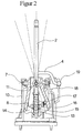
- FIG. 2 shows a rear view of the embodiment according to the invention of the switching device 1.
- a sliding block 13 is formed at the lower free end of the shift lever 2, a sliding block 13 is formed.
- a recess 14 is provided, which allows a play-free mounting of the shift lever 2 in the cross piece 8 together with the arranged in the recess 14 sliding block 13.
- a roller 15 is fixed, which rolls on the path predetermined by a gate 16 of the crosspiece 8 web.
- the dashed lines represent with the roller 15 shown in various positions, the various possible areas in which the shift lever 2 can be pivoted to switch in the various shift gates.
- a coil spring 17 may be arranged, which supports a return of the shift lever 2 in a predetermined shift gate, in which, for example, to be preferably switched. Due to the shape of the link 16 of the crosspiece 8 in the region of the running surface of the roller 15, the switching characteristic of the switching device can be variable be determined. About the steepness of the tread of the roller on the gate 16 of the crosspiece 8, the change from shift gate to shift gate can be made easy or stiff, as only against the spring force of the coil spring 17, the change of the shift gate is possible.
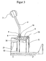
- FIG. 3 shows a side view of the embodiment of the switching device according to the invention 1.
- the selector lever 5 has a movement window 20, which is a movement of a bearing shell 19 in the selector lever 5 in the direction of the switching movement by the shift finger 4 when switching in shift lanes outside the central shift gate on a Circular path takes place, allows.
- a stop 21 and a further stop, not shown, are provided on the housing 9, which limit the switching movement in the direction of the switching movement.
- An attached to the cross piece elastomer damper 22 and another damper not shown provide a damage-free suspension of the crosspiece 8 upon reaching the limit of the switching movement performing stops 21st
- the shift lever is pivoted in the direction of the selection movement transversely to the direction of travel, and the selector lever 5 thereby by means of a shift finger 4, which is integrally formed on the shift lever 2, pivots.
- a shift finger 4 which is integrally formed on the shift lever 2, pivots.
- Analog becomes pivoted at a pivoting movement of the shift lever 2 to the left of the selector lever 5 by means of the shift finger, whereby the lower free end of the selector lever 5 moves backwards.
- a movement gap 18 is provided in the selector lever 5, which allows movement of the bearing shell 19 during pivoting of the shift lever 2 in the direction of the selection movement.
- the bearing shell 19 is moved according to the right in the movement gap 18 in the direction of the selection movement within the selector lever 5.
- a pivoting of the shift lever 2 to the left in the direction of the selection movement analogously causes a displacement of the bearing shell 19 to the left in the movement gap 18 within the selector lever fifth
- the shift lever is located in one of the outer shift lanes, it is additionally necessary for a shift movement to mount the ball joint 6 or the bearing shell 19 of the ball joint movably in the selector lever 5 for mounting the shift finger 4 in the direction of the shift movement.
- a movement window 20 is provided in the selector lever 5, which allows movement of the bearing shell 19 when pivoting the shift lever 2 in the direction of the switching movement.
- the bearing shell 19 is moved accordingly forward in the movement window 20 in the direction of travel within the selector lever 5.
- a pivoting of the shift lever 2 towards the rear in the direction of the switching movement causes a similar displacement of the bearing shell 19 to the rear in the movement window 20 within the selector lever fifth
- FIG. 2 a way to set up a bumper 24, for example, for a protection against accidental engagement of the reverse gear shown schematically.
- the shift lever 2 To engage the reverse gear, the shift lever 2 must be pivoted completely to the left in the example shown.
- the impact barrier 24 is designed in the form of a projection. To overcome this projection requires a considerably larger force than in the pivoting of the shift lever 2 for selecting a different shift gate. A shift in this shift gate can only be made possible by greater force (eg impact) or by a possibly provided unlocking.
Landscapes
- Engineering & Computer Science (AREA)
- General Engineering & Computer Science (AREA)
- Mechanical Engineering (AREA)
- Arrangement Or Mounting Of Control Devices For Change-Speed Gearing (AREA)
- Gear-Shifting Mechanisms (AREA)
Description
Die vorliegende Erfindung betrifft eine Schalteinrichtung für ein Getriebe gemäß den Merkmalen des Oberbegriffes des unabhängigen Anspruches 1.The present invention relates to a shifting device for a transmission according to the features of the preamble of
Derartige Schalteinrichtungen sind beispielsweise aus der
In der
In der
Es ist daher Aufgabe der vorliegenden Erfindung, eine Schaltvorrichtung bereitzustellen, bei der Schalt- und Wählbewegung weitestgehend entkoppelt sind, und die einfacher und zuverlässiger herzustellen, zu montieren und zu betreiben ist.It is therefore an object of the present invention to provide a switching device in which switching and selection movement are largely decoupled, and which is easier and more reliable to manufacture, assemble and operate.
Diese Aufgabe wird erfindungsgemäß mit einer Schalteinrichtung gemäß den Merkmalen des Anspruches 1 gelöst. Weitere vorteilhafte Ausgestaltungen der erfindungsgemäßen Schalteinrichtung nach Anspruch 1 ergeben sich durch die Merkmale der Unteransprüche.This object is achieved with a switching device according to the features of
Die erfindungsgemäße Schalteinrichtung weist einen Schalthebel auf, der kardanisch über zwei definiert festgelegte Schwenkachsen gelagert ist. Schaltzug und Wählzug sind örtlich voneinander getrennt, und Schalt- und Wählbewegung sind voneinander entkoppelt. Da ein Kreuzstück mit einem daran in einem Abstand von der Schaltachse befestigten Schalthebel vorgesehen ist, welches in einem Gehäuse um die Schaltachse schwenkbar gelagert ist, wobei die Verschwenkung in Richtung der Schaltbewegung, die durch Mitnahme des Kreuzstückes durch den zur Ausführung der Schaltbewegung verschwenkten Schalthebel erfolgt, den an dem unteren freien Ende des Kreuzstücks befestigten und somit nicht direkt mit dem Schalthebel verbundenen Schaltzug betätigt, erfährt der Schaltzug während des Schaltvorganges nur geringfügige Winkelauslenkungen gemäß der Kreisbahn, die das Kreuzstück bei dem Verschwenken beschreibt, was einer nahezu linearen Bewegung gleichzusetzen ist. Durch diese geringfügige Auslenkung des Schaltzuges bleibt der Kraftangriffspunkt nahezu konstant, wodurch auch der Wirkungsgrad, der bei größeren Winkelauslenkungen der Seilzüge abnimmt, ebenfalls konstant bleibt und auch die Lebensdauer des Schaltzuges wird aufgrund der gleichförmigen Belastung heraufgesetzt.The switching device according to the invention has a shift lever which is mounted gimbal over two defined pivot axes. Shift cable and selector cable are locally separated, and switching and selection movement are decoupled from each other. Since a cross piece is provided with an attached thereto at a distance from the shift axis shift lever, which is pivotally mounted in a housing about the shift axis, wherein the pivoting in the direction of the switching movement by the entrainment of Crosspiece is carried by the pivoted to execute the switching movement of the shift lever, which is attached to the lower free end of the crosspiece and thus not directly connected to the shift lever shift cable, learns the Schaltzug during the switching process only slight Winkelauslenkungen according to the circular path, the crosspiece in the pivoting describes what equates to a nearly linear motion. Due to this slight deflection of the shift cable of the force application point remains almost constant, whereby the efficiency, which decreases with larger angular deflections of the cables, also remains constant and the life of the shift cable is increased due to the uniform load.
Ferner ist der Schalthebel über einen an dem unteren freien Ende des Schalthebels in einem Abstand von der Schaltachse angeordneten Gleitstein in Richtung der Schaltbewegung spielfrei in dem Kreuzstück geführt, so dass zum Ausführen des Schaltvorganges aufgrund des so gegebenen Hebels nur geringe Kräfte zur Mitnahme des Kreuzstückes eingebracht werden müssen. Der Gleitstein an dem unteren freien Ende sorgt durch die spielfreie Lagerung zusätzlich für eine exakte Führung des Schalthebels bei dem Verschwenken des Schalthebels in Richtung der Wählbewegung, indem er in einer in dem Kreuzstück vorgesehenen Aussparung entsprechend der Bewegung des Schalthebels hin und her gleitet.Further, the shift lever is guided over a free on the lower free end of the shift lever at a distance from the shift axis sliding block in the direction of the switching movement in the cross piece, so that introduced to perform the switching operation due to the lever so given only small forces to take the cross piece Need to become. The sliding block at the lower free end additionally ensures, due to the play-free mounting, an exact guidance of the shift lever during the pivoting of the shift lever in the direction of the selection movement by sliding back and forth in a recess provided in the crosspiece in accordance with the movement of the shift lever.
Es ist vorteilhaft, die Wählachse in dem Kreuzstück anzuordnen, und den Schalthebel auf der Wählachse schwenkbar zu lagern, da so die zwei von einander entkoppelte Schwenkachsen definiert geführt sind. Ein Verschwenken des Wählhebels über den Schaltknauf durch den Fahrer wird dadurch unterbunden, wodurch die Gefahr eines etwaigen Verkantens des Schalthebels bzw. der Beschädigung der Schalteinrichtung verringert wird. Weiterhin vorteilhaft erweist sich dabei, dass durch diese Anordnung bei dem Verschwenken des Schalthebels um die Wählachse das Kreuzstück im wesentlichen in Ruhe bleibt, da somit der Schaltzug bei dem Verschwenken des Schalthebels in Richtung der Wählbewegung ebenfalls in Ruhe bleibt und keine Winkeländerungen erfährt.It is advantageous to arrange the selector axis in the crosspiece, and to store the shift lever on the selector axis pivotally, since so the two mutually decoupled pivot axes are guided defined. A pivoting of the selector lever on the shift knob by the driver is thereby prevented, whereby the risk of any tilting of the shift lever or the damage of the switching device is reduced. Furthermore, it proves to be advantageous that remains by this arrangement in the pivoting of the shift lever to the selector axis, the crosspiece substantially at rest, since thus the shift cable also remains at rest during the pivoting of the shift lever in the direction of the selection movement and undergoes no changes in angle.
Weiterhin weist das Gleitstück vorteilhaft eine Walze auf, die ein Verschwenken des Schalthebels zum Ausrühren der Wählbewegung durch Abrollen auf einer von der Kulisse des Kreuzstückes festgelegten Bahn ermöglicht, wobei das Kreuzstück im wesentlichen in Ruhe bleibt und die Ausgestaltung der Kulisse des Kreuzstückes in dem Bereich der Lauffläche der Walze die Schaltcharakteristik festlegt. Durch die Steilheit der Kulisse wird die Kraft bestimmt, die aufgewendet werden muß, um den Schalthebel entgegen der Federkraft der Schraubenfeder zu bewegen.Furthermore, the slider advantageously has a roller which allows pivoting of the shift lever for stirring the selection movement by rolling on a fixed path of the backdrop of the crosspiece, the crosspiece remains essentially at rest and the design of the backdrop of the crosspiece in the field of Tread of the roller determines the switching characteristic. Due to the steepness of the backdrop, the force is determined which must be used to move the shift lever against the spring force of the coil spring.
Des weiteren kann vorteilhaft die Lauffläche der Walze in dem Kreuzstück so ausgebildet werden, dass eine Schlagsperre ein ungewolltes Einlegen des Rückwärtsganges unterbindet. Dies kann beispielsweise durch Einbringung von Stegen erfolgen, die ein Schalten in diese Schaltgasse nur durch größeren Kraftaufwand oder durch eine eventuell vorgesehene Entriegelung ermöglicht.Furthermore, advantageously, the running surface of the roller can be formed in the cross piece so that a striking lock prevents unintentional engagement of the reverse gear. This can be done for example by the introduction of webs, which allows switching in this shift gate only by greater force or by a possibly provided unlocking.
Der Schalthebel weist weiterhin vorteilhaft einen Schaltfinger auf, der mittels eines Kugelgelenkes in einem zusätzlich vorhandenen Wählhebel der Schalteinrichtung schwenkbar gelagert ist und der bei dem Verschwenken des Schalthebels über den Wählhebel einen Wählzug betätigt. Der Wählhebel wird beim Verschwenken des Schalthebels über den an dem Schalthebel angeformten Schaltfinger an seinem oberen freien Ende nach oben bzw. nach unten bewegt. Er kann winklig ausgeführt und an seinem Scheitelpunkt derart gelagert sein, dass von den durch den Schaltfinger hervorgerufenen Auf- und Abbewegungen der Wählzug, der an dem anderen freien Ende des Wählhebels fixiert ist, nahezu linear vor- und zurück bewegt wird. Dabei wird der Schaltfinger aufgrund der Hebelwirkung und der Übersetzung, die durch die Formgebung des Wählhebels erreicht wird, bei dem Betätigen des Wählzuges keinen großen Biege- und Torsionsmomenten ausgesetzt, da so die benötigte Krafteinleitung zur Betätigung des Schalthebels gering ist.The shift lever further advantageously has a shift finger which is pivotally mounted by means of a ball joint in an additionally existing selector lever of the switching device and which actuates a Wählzug during the pivoting of the shift lever via the selector lever. The selector lever is moved when pivoting the shift lever via the integrally formed on the shift lever shift finger at its upper free end up or down. It can be performed at an angle and be mounted at its apex so that of the caused by the shift finger up and down movements of the Wählzug, which is fixed to the other free end of the selector lever is moved almost linearly back and forth. In this case, the shift finger is due to the leverage and the translation, which is achieved by the shape of the selector lever, exposed to the operation of the Wählzuges no large bending and torsional moments, since so the required application of force to operate the shift lever is low.
Die Lagerschale des Kugelgelenkes, in der der Schaltfinger des Schalthebels gelagert ist, ist vorteilhaft derart in den Wählhebel eingesetzt, dass sie zum Höhenausgleich bei Verschwenkung des Schalthebels in Richtung der Wählbewegung geringfügige Auslenkungen in Richtung der Wählbewegung ausführen kann.The bearing shell of the ball joint, in which the shift finger of the shift lever is mounted, is advantageously inserted into the selector lever so that it can perform slight deflections in the direction of the selector movement for height compensation during pivoting of the shift lever in the direction of the selection movement.
Weiterhin weist der Wählhebel vorteilhaft weitere Aussparungen auf, die eine Bewegung der Lagerschale in dem Wählhebel entsprechend der bei dem Schalten in einer äußeren Schaltgasse durch den Schaltfinger des Schalthebels beschriebenen Kreisbahn ermöglicht.Furthermore, the selector lever advantageously further recesses, which allows a movement of the bearing shell in the selector lever according to the circular path described in the switching in an outer shift gate by the shift finger of the shift lever.
Gegenüber dem Stand der Technik stellt die erfindungsgemäße Schalteinrichtung demnach eine wesentlich einfachere und weniger wartungsintensive Ausführung dar, da lediglich ein Kugelgelenk zur Lagerung des Schaltfingers eingesetzt wird und durch den Einsatz zweier festgelegter Achsen, über die Schalt- und Wählzug indirekt betätigt werden, die Bewegung des Schalthebels auf exakten Bahnen verläuft und dadurch die Gefahr eines etwaigen Verkantens des Schaltknaufes bzw. ein Ausknöpfen eines Kugelgelenkes durch eventuelles Verschwenken des Schalthebels durch den Fahrer des Kraftfahrzeuges oder bei extremen Auslenkungen des Schalthebels zum Schalten in den außenliegenden Schaltgassen verringert wird.Compared to the prior art, the switching device according to the invention therefore represents a much simpler and less maintenance-intensive design, since only a ball joint is used to support the shift finger and are indirectly actuated by the use of two fixed axes on the shift and Wählzug, the movement of the Shift lever runs on exact tracks and thereby the risk of any tilting of the shift knob or a Ausknöpfen a ball joint is reduced by any pivoting of the shift lever by the driver of the motor vehicle or extreme deflections of the shift lever for switching in the outer shift gates.
Nachfolgend wird ein Ausführungsbeispiel der erfindungsgemäßen Schalteinrichtung anhand der Zeichnung näher erläutert.An embodiment of the switching device according to the invention will be explained in more detail with reference to the drawing.
Es zeigen:
- Figur 1:
- eine perspektivische Darstellung der Schalteinrichtung;
- Figur 2:
- eine Rückansicht der Schalteinrichtung mit verschiedenen Positionen des Schalthebels;
und - Figur 3:
- eine Seitenansicht der Schalteinrichtung von links.
- FIG. 1:
- a perspective view of the switching device;
- FIG. 2:
- a rear view of the switching device with different positions of the shift lever;
and - FIG. 3:
- a side view of the switching device from the left.
Das Kreuzstück 8 ist über zwei Verbindungsstücke achsgelagert. Diese Achslagerung ist an einem Gehäuse 10 beidseitig fixiert. Sie ermöglicht ein Verschwenken des Kreuzstückes 8 in Richtung der Schaltbewegung, wobei die Richtung der Schaltbewegung in dem Ausführungsbeispiel in Fahrtrichtung des Kraftfahrzeuges senkrecht zur Richtung der Wählbewegung ausgerichtet ist. Weiterhin weist das Kreuzstück 8 an seinem unteren freien Ende eine Befestigungsmöglichkeit 9 für einen nicht dargestellten Seilzug, den Schaltzug, auf.The
Der Wählhebel 5 ist in dem Ausführungsbeispiel mit einem 90°-Winkel ausgeführt. Er ist in dem Winkelbereich mittels einer Bolzenverbindung in dem Gehäuse 10 gelagert. An seinem unteren freien Ende weist der Wählhebel 5 eine Befestigungsmöglichkeit 12 für einen Wählzug auf.The
Bei Betätigung des Schalthebels 2 in Richtung der Schaltbewegung wird über das Kreuzstück 8 der nicht dargestellte Schaltzug je nach Schaltvorgang nach vorne bzw. zurück bewegt. Dadurch wird der Gangwechsel in dem nicht dargestellten Getriebe eingeleitet. Bei einem Verschwenken des Schalthebels 2 in Richtung der Schaltbewegung bleibt der Wählhebel 5 und somit auch der nicht dargestellte Wählzug in Ruhe, da der in dem Wählhebel 5 gelagerte Schaltfinger 4 sich bei dieser Bewegung lediglich eine Schwenkbewegung in dem Kugelgelenk 6 ausführt.Upon actuation of the
Zur Betätigung des Wählzuges wird der Schalthebel in Richtung der Wählbewegung quer zur Fahrtrichtung verschwenkt, und der Wählhebel 5 dabei mittels eines Schaltfingers 4, der an dem Schalthebel 2 angeformt ist, verschwenkt. Wird nun der Schalthebel 2 beispielsweise nach rechts verschwenkt, so wird über den Schaltfinger 4 der Wählhebel 5 an seinem oberen freien Ende nach unten gedrückt. Dies ruft eine Verschwenkung des Wählhebels 5 um die Bolzenverbindung 23 hervor, wodurch das untere freie Ende des Wählhebels 5 nach vorne geschoben wird. Dadurch wird schließlich der Wählzug betätigt und der entsprechende Schaltgassenwechsel an das Getriebe weitergeleitet. Analog wird bei einer Schwenkbewegung des Schalthebels 2 nach links der Wählhebel 5 mittels des Schaltfingers nach oben gedrückt, wodurch sich das untere freie Ende des Wählhebels 5 nach hinten bewegt. Bei Verschwenken des Schalthebels in Richtung der Wählbewegung zum Wechsel der Schaltgassen gleitet der Gleitstein 13 entsprechend nach rechts bzw. links.To actuate the Wählzuges the shift lever is pivoted in the direction of the selection movement transversely to the direction of travel, and the
Um ein Verschwenken des Schalthebels 2 in die außen gelegenen Positionen zu ermöglichen, ist es notwendig, das Kugelgelenk 6 bzw. die Lagerschale 19 des Kugelgelenkes in dem Wählhebel 5 zur Lagerung des Schaltfingers 4 in Richtung der Wählbewegung beweglich zu lagern. Dafür ist in dem Wählhebel 5 ein Bewegungsspalt 18 vorgesehen, der eine Bewegung der Lagerschale 19 bei Verschwenken des Schalthebels 2 in Richtung der Wählbewegung ermöglicht. Bei Verschwenken des Schalthebels 2 nach rechts wird die Lagerschale 19 entsprechend nach rechts in dem Bewegungsspalt 18 in Richtung der Wählbewegung innerhalb des Wählhebels 5 verschoben. Ein Verschwenken des Schalthebels 2 nach links in Richtung der Wählbewegung bewirkt analog eine Verschiebung der Lagerschale 19 nach links in dem Bewegungsspalt 18 innerhalb des Wählhebels 5.In order to enable a pivoting of the
Bei sämtlichen Bewegungen in Richtung der Wählbewegung bleibt das Kreuzstück 8 in Ruhe, so dass das Verschwenken des Schalthebels 2 in Richtung der Wählbewegung keine Winkeländerung des Kraftangriffspunktes des Schaltzuges zur Folge hat, was gleichbedeutend mit einem konstanten Wirkungsgrad der Schalteinrichtung 1 ist.In all movements in the direction of the selection movement, the
Befindet sich der Schalthebel in einer der äußeren Schaltgassen, ist es zum Ausführen einer Schaltbewegung zusätzlich notwendig, das Kugelgelenk 6 bzw. die Lagerschale 19 des Kugelgelenkes in dem Wählhebel 5 zur Lagerung des Schaltfingers 4 in Richtung der Schaltbewegung beweglich zu lagern. Dafür ist in dem Wählhebel 5 ein Bewegungsfenster 20 vorgesehen, der eine Bewegung der Lagerschale 19 bei Verschwenken des Schalthebels 2 in Richtung der Schaltbewegung ermöglicht. Bei Verschwenken des Schalthebels 2 nach vorne in Fahrtrichtung wird die Lagerschale 19 entsprechend nach vorne in dem Bewegungsfenster 20 in Fahrtrichtung innerhalb des Wählhebels 5 verschoben. Ein Verschwenken des Schalthebels 2 nach hinten in Richtung der Schaltbewegung entgegen der Fahrtrichtung bewirkt analog eine Verschiebung der Lagerschale 19 nach hinten in dem Bewegungsfenster 20 innerhalb des Wählhebels 5.If the shift lever is located in one of the outer shift lanes, it is additionally necessary for a shift movement to mount the ball joint 6 or the bearing
In diesem Ausführungsbeispiel ist insbesondere in
- 1:1:
- Schalteinheitswitching unit
- 2:2:
- Schalthebelgear lever
- 3:3:
- Schaltknaufshift knob
- 4:4:
- Schaltfingershift finger
- 5:5:
- Wählhebelselector lever
- 6:6:
- Kugelgelenkball joint
- 7:7:
- Bolzenverbindung für Schaltachse SchalthebelBolt connection for indexing shaft Shift lever
- 8:8th:
- Kreuzstückcrosspiece
- 9:9:
- Befestigungsmöglichkeit SchaltzugFixing possibility of shift cable
- 10:10:
- Gehäusecasing
- 11:11:
- Bolzenverbindung für Wählachse SchalthebelBolt connection for selector shaft Shift lever
- 12:12:
- Befestigungseinrichtung WählzugFastening device Selector cable
- 13:13:
- Gleitsteinslide
- 14:14:
- Aussparung zur Führung des GleitsteinesRecess for guiding the sliding block
- 15:15:
- Walzeroller
- 16:16:
- Kulisse des KreuzstückesScenery of the cross piece
- 17:17:
- Federfeather
- 18:18:
- Bewegungsspaltmovement gap
- 19:19:
- Lagerschalebearing shell
- 20:20:
- Bewegungsfenstermotion window
- 21:21:
- Anschlag KreuzstückStop crosspiece
- 22:22:
- Elastomerdämpfer für AnschlagElastomer damper for stop
- 23:23:
- Bolzenverbindung WählhebelBolt connection selector lever
- 24:24:
- Schlagsperrearrestor
Claims (9)
- Selector device for a transmission of a motor vehicle having a shift pattern which has at least two shift gates which are oriented approximately in the longitudinal direction of the motor vehicle and at least one selector gate which is arranged transversely with respect to the shift gates, having a gearshift lever (2) which is mounted such that it can be pivoted about two pivot pins, a first pivot pin forming a shift pin, a further pivot pin forming a selecting pin, and it being possible for a shift movement to be carried out in the direction of a shift gate and for a selecting movement to be carried out in the direction of the selector gate by way of pivoting of the gearshift lever (2), the selecting and shift movements being decoupled from one another, a crosspiece (8) with a gearshift lever (2) which is fastened on it at a spacing from the pivot pin being mounted in a housing (10) such that it can be pivoted about the pivot pin, and the shifting cable which is fastened to the lower free end of the crosspiece (8) being actuated by driving of the crosspiece (8) as a result of the pivoting of the gearshift lever (2) in the direction of the shift movement, characterized in that the gearshift lever (2) is guided without play in the crosspiece (8) in the direction of the shift movement via a sliding block (13) which is arranged at a lower free end of the gearshift lever (2) at a spacing from the shift pin.
- Selector device according to Claim 1, characterized in that the selecting pin is arranged in the crosspiece (8), and the gearshift lever (2) is mounted pivotably on the selecting pin.
- Selector device according to one of the preceding claims, characterized in that the crosspiece (8) remains substantially at rest during the pivoting of the gearshift lever (2) about the selecting pin.
- Selector device according to one of the preceding claims, characterized in that the sliding block (13) has a roller (15) which makes pivoting of the gearshift lever (2) possible in order to carry out the selecting movement on a track which is fixed by the crosspiece (8), the crosspiece (8) remaining substantially at rest.
- Selector device according to Claim 4, characterized in that the design of a slotted guide (16) of the crosspiece (8) in the region of the running face of the roller (15) fixes the shifting characteristic.
- Selector device according to Claim 5, characterized in that the running face of the roller (15) of the slotted guide (16) of the crosspiece (8) is configured in such a way that a safety lock prevents undesired engagement of the reverse gear.
- Selector device according to one of the preceding claims, characterized in that the gearshift lever (2) has a selector finger (4) which is mounted pivotably in a bearing of a selector lever (5) and in which pivoting of the gearshift lever (2) actuates a selector cable via the selector lever (5).
- Selector device according to Claim 7, characterized in that a bearing shell (19), in which the selector finger (4) of the gearshift lever (2) is mounted in the selector lever (5), can carry out slight deflections in a movement gap (18) for height compensation during pivoting of the gearshift lever (2) in the direction of the selecting movement.
- Selector device according to Claim 8, characterized in that the selector lever (5) has a movement window (20) which makes a movement of the bearing shell (19) in the selector lever (5) possible in accordance with the circular path which is described by the selector finger (4) of the gearshift lever (2) during shifting in an outer shift gate.
Applications Claiming Priority (2)
| Application Number | Priority Date | Filing Date | Title |
|---|---|---|---|
| DE10353240A DE10353240A1 (en) | 2003-11-13 | 2003-11-13 | switching device |
| DE10353240 | 2003-11-13 |
Publications (3)
| Publication Number | Publication Date |
|---|---|
| EP1531290A2 EP1531290A2 (en) | 2005-05-18 |
| EP1531290A3 EP1531290A3 (en) | 2010-09-22 |
| EP1531290B1 true EP1531290B1 (en) | 2012-12-26 |
Family
ID=34428734
Family Applications (1)
| Application Number | Title | Priority Date | Filing Date |
|---|---|---|---|
| EP04026154A Not-in-force EP1531290B1 (en) | 2003-11-13 | 2004-11-04 | Gear selector device |
Country Status (3)
| Country | Link |
|---|---|
| US (1) | US20050160861A1 (en) |
| EP (1) | EP1531290B1 (en) |
| DE (1) | DE10353240A1 (en) |
Families Citing this family (10)
| Publication number | Priority date | Publication date | Assignee | Title |
|---|---|---|---|---|
| DE102008017862B4 (en) * | 2008-04-09 | 2022-01-27 | Dr. Ing. H.C. F. Porsche Aktiengesellschaft | Operating device for a manual transmission |
| DE102008017861A1 (en) * | 2008-04-09 | 2009-10-29 | Dr. Ing. H.C. F. Porsche Aktiengesellschaft | Control mechanism for manual transmission of motor vehicle, has H-connecting rod exhibiting adjusting paths within respective longitudinal lane for switching forward gear of one longitudinal lane larger than other forward gears |
| DE102009037067A1 (en) * | 2009-08-13 | 2011-02-17 | GM Global Technology Operations, Inc., Detroit | Circuit housing of a vehicle with a selector lever and method for mounting the selector lever on the circuit housing |
| DE102009037068A1 (en) * | 2009-08-13 | 2011-02-17 | GM Global Technology Operations, Inc., Detroit | Bearing bush in particular for a circuit housing of a vehicle and method for mounting the bearing bush |
| US20140165768A1 (en) * | 2012-12-13 | 2014-06-19 | Eaton Corporation | Push down shifter with cross joint |
| DE102015015880A1 (en) * | 2015-12-09 | 2017-06-14 | GM Global Technology Operations LLC (n. d. Ges. d. Staates Delaware) | External circuit for a manual transmission |
| FR3049037B1 (en) * | 2016-03-18 | 2019-08-02 | Peugeot Citroen Automobiles Sa | DEVICE FOR CONTROLLING A GEARBOX FOR A MOTOR VEHICLE COMPRISING A SELECTION REFERENCE |
| KR101905950B1 (en) | 2016-04-08 | 2018-10-08 | 현대자동차주식회사 | Shift-lever assembly of manual transmission |
| EP3447339B1 (en) | 2017-08-23 | 2021-05-26 | Fico Triad, S.A. | Gearshift assembly for motor vehicles |
| CN108547941A (en) * | 2018-06-21 | 2018-09-18 | 洛阳市黄河软轴控制器股份有限公司 | Trailer reversing control mechanism and its application method |
Citations (2)
| Publication number | Priority date | Publication date | Assignee | Title |
|---|---|---|---|---|
| US5287743A (en) * | 1992-09-24 | 1994-02-22 | Dura Mechanical Components, Inc. | Manual transmission shifter |
| DE19537899A1 (en) * | 1994-10-13 | 1996-04-18 | Tsuda Ind | Shift lever fitting for manual transmission |
Family Cites Families (15)
| Publication number | Priority date | Publication date | Assignee | Title |
|---|---|---|---|---|
| US4328712A (en) * | 1980-01-24 | 1982-05-11 | Jsj Corporation | Lockout for gimbal-type automotive transmission gear shifter |
| JPS6361639A (en) * | 1986-09-02 | 1988-03-17 | Nippon Cable Syst Inc | Transmission control |
| DE4029330A1 (en) * | 1990-09-15 | 1992-03-26 | Porsche Ag | SWITCHING DEVICE FOR A MOTOR VEHICLE TRANSMISSION |
| DE4426207C5 (en) * | 1994-07-23 | 2008-08-28 | Bayerische Motoren Werke Aktiengesellschaft | Selection device for an automatic transmission of a motor vehicle |
| DE19549437C2 (en) * | 1995-07-17 | 1999-06-10 | Lemfoerder Metallwaren Ag | Switching device for an automatic transmission of a motor vehicle |
| US5681490A (en) * | 1995-09-18 | 1997-10-28 | Chang; Dale U. | Laser weld quality monitoring system |
| DE19600526C2 (en) * | 1996-01-10 | 1998-02-19 | Lemfoerder Metallwaren Ag | Switching device for an automatic transmission of a motor vehicle |
| ES2162141T3 (en) * | 1996-03-08 | 2001-12-16 | Zf Lemfoerder Metallwaren Ag | SWITCHING DEVICE FOR A CHANGE OF MOTOR VEHICLES. |
| DE19637254C2 (en) * | 1996-09-13 | 1998-07-30 | Lemfoerder Metallwaren Ag | Selector device for an automatic transmission of motor vehicles |
| US5845536A (en) * | 1997-03-21 | 1998-12-08 | Saturn Corporation | Transmission shift control mechanism |
| DE19739632A1 (en) | 1997-09-10 | 1999-03-11 | Volkswagen Ag | Switching device for manual actuation of a manual transmission |
| DE19817166B4 (en) * | 1998-04-17 | 2008-01-31 | Fico Triad S.A., Rubi | lever element |
| DE19918508C2 (en) * | 1999-04-23 | 2001-04-19 | Daimler Chrysler Ag | Switching device |
| DE19946817C1 (en) * | 1999-09-30 | 2001-01-25 | Daimler Chrysler Ag | Manual vehicle gearbox with cogwheels has an intermediate gear shift lever with a locked movement with the gear change member and a direct bond to the linkage carrier through the connecting linkages |
| EP1333199B1 (en) * | 2002-01-31 | 2007-01-24 | Schaeffler KG | Device for increasing a selection force |
-
2003
- 2003-11-13 DE DE10353240A patent/DE10353240A1/en not_active Ceased
-
2004
- 2004-10-28 US US10/976,250 patent/US20050160861A1/en not_active Abandoned
- 2004-11-04 EP EP04026154A patent/EP1531290B1/en not_active Not-in-force
Patent Citations (2)
| Publication number | Priority date | Publication date | Assignee | Title |
|---|---|---|---|---|
| US5287743A (en) * | 1992-09-24 | 1994-02-22 | Dura Mechanical Components, Inc. | Manual transmission shifter |
| DE19537899A1 (en) * | 1994-10-13 | 1996-04-18 | Tsuda Ind | Shift lever fitting for manual transmission |
Also Published As
| Publication number | Publication date |
|---|---|
| US20050160861A1 (en) | 2005-07-28 |
| EP1531290A2 (en) | 2005-05-18 |
| DE10353240A1 (en) | 2005-06-16 |
| EP1531290A3 (en) | 2010-09-22 |
Similar Documents
| Publication | Publication Date | Title |
|---|---|---|
| DE102005001818B4 (en) | Switching device for an automatic transmission of a motor vehicle | |
| DE19882218B4 (en) | Gearbox with a central selector shaft | |
| WO2006125608A1 (en) | Electric switching device for a motor vehicle | |
| DE102005060933B3 (en) | Gear selector lever e.g. shift-by-wire lever, for e.g. commercial vehicle, has haptic unit formed by pressure unit, gear wheels, motor and/or damper and producing force path of lever, where unit is fixedly arranged with respect to housing | |
| DE19853934B4 (en) | Switching device of a motor vehicle transmission | |
| DE3824296C2 (en) | ||
| EP2222985B1 (en) | Locking segment for a transmission element in a switching device and switching device having the locking segment | |
| EP1531290B1 (en) | Gear selector device | |
| EP1432885A1 (en) | Device for adjusting a window pane displaced by a double-stranded cable window lifter on a motor vehicle | |
| EP1825171B1 (en) | Shifting device of a manual gearbox for a motor vehicle | |
| EP1817513B1 (en) | Shifting console of a motor vehicle transmission | |
| EP2486309A1 (en) | Shifting device | |
| DE19520209B4 (en) | Switching mechanism for a manually shiftable transmission | |
| DE10039305B4 (en) | Guide mechanism for a cover plate of a storage compartment in a vehicle | |
| EP3752694B1 (en) | Car parking device | |
| EP1082557A1 (en) | Shifting device for motor vehicles | |
| EP1117950B1 (en) | Selector device for a vehicle with an automatic gear system | |
| DE102007058823A1 (en) | Actuator with variable range of motion | |
| EP1267240A1 (en) | Gear change device for a manual transmission of a motor vehicle | |
| EP3628891A1 (en) | Guide arrangement with multiple guide tracks | |
| EP3187753B1 (en) | Gear selection lever device for selecting and/or switching gear stages of the gearbox of a motor vehicle | |
| DE19900412A1 (en) | Selection arrangement for motor vehicle automatic gearbox has gear change axle mounted to move along guide, perpendicularly to itself and elastically about central position | |
| EP0957296B1 (en) | Device for selecting and shifting between predetermined positions | |
| EP1245872A1 (en) | Shift actuator for a change-speed gearbox, particularly for vehicles | |
| DE102004033672B4 (en) | Switching device for an automatic transmission |
Legal Events
| Date | Code | Title | Description |
|---|---|---|---|
| PUAI | Public reference made under article 153(3) epc to a published international application that has entered the european phase |
Free format text: ORIGINAL CODE: 0009012 |
|
| AK | Designated contracting states |
Kind code of ref document: A2 Designated state(s): AT BE BG CH CY CZ DE DK EE ES FI FR GB GR HU IE IS IT LI LU MC NL PL PT RO SE SI SK TR |
|
| AX | Request for extension of the european patent |
Extension state: AL HR LT LV MK YU |
|
| PUAL | Search report despatched |
Free format text: ORIGINAL CODE: 0009013 |
|
| AK | Designated contracting states |
Kind code of ref document: A3 Designated state(s): AT BE BG CH CY CZ DE DK EE ES FI FR GB GR HU IE IS IT LI LU MC NL PL PT RO SE SI SK TR |
|
| AX | Request for extension of the european patent |
Extension state: AL HR LT LV MK YU |
|
| 17P | Request for examination filed |
Effective date: 20101207 |
|
| 17Q | First examination report despatched |
Effective date: 20110214 |
|
| AKX | Designation fees paid |
Designated state(s): AT BE BG CH CY CZ DE DK EE ES FI FR GB GR HU IE IS IT LI LU MC NL PL PT RO SE SI SK TR |
|
| GRAP | Despatch of communication of intention to grant a patent |
Free format text: ORIGINAL CODE: EPIDOSNIGR1 |
|
| GRAS | Grant fee paid |
Free format text: ORIGINAL CODE: EPIDOSNIGR3 |
|
| GRAA | (expected) grant |
Free format text: ORIGINAL CODE: 0009210 |
|
| AK | Designated contracting states |
Kind code of ref document: B1 Designated state(s): AT BE BG CH CY CZ DE DK EE ES FI FR GB GR HU IE IS IT LI LU MC NL PL PT RO SE SI SK TR |
|
| REG | Reference to a national code |
Ref country code: GB Ref legal event code: FG4D Free format text: NOT ENGLISH |
|
| REG | Reference to a national code |
Ref country code: CH Ref legal event code: EP |
|
| REG | Reference to a national code |
Ref country code: AT Ref legal event code: REF Ref document number: 590667 Country of ref document: AT Kind code of ref document: T Effective date: 20130115 |
|
| REG | Reference to a national code |
Ref country code: DE Ref legal event code: R096 Ref document number: 502004013960 Country of ref document: DE Effective date: 20130228 |
|
| PG25 | Lapsed in a contracting state [announced via postgrant information from national office to epo] |
Ref country code: FI Free format text: LAPSE BECAUSE OF FAILURE TO SUBMIT A TRANSLATION OF THE DESCRIPTION OR TO PAY THE FEE WITHIN THE PRESCRIBED TIME-LIMIT Effective date: 20121226 Ref country code: SE Free format text: LAPSE BECAUSE OF FAILURE TO SUBMIT A TRANSLATION OF THE DESCRIPTION OR TO PAY THE FEE WITHIN THE PRESCRIBED TIME-LIMIT Effective date: 20121226 |
|
| REG | Reference to a national code |
Ref country code: NL Ref legal event code: VDEP Effective date: 20121226 |
|
| PG25 | Lapsed in a contracting state [announced via postgrant information from national office to epo] |
Ref country code: SI Free format text: LAPSE BECAUSE OF FAILURE TO SUBMIT A TRANSLATION OF THE DESCRIPTION OR TO PAY THE FEE WITHIN THE PRESCRIBED TIME-LIMIT Effective date: 20121226 Ref country code: GR Free format text: LAPSE BECAUSE OF FAILURE TO SUBMIT A TRANSLATION OF THE DESCRIPTION OR TO PAY THE FEE WITHIN THE PRESCRIBED TIME-LIMIT Effective date: 20130327 |
|
| PG25 | Lapsed in a contracting state [announced via postgrant information from national office to epo] |
Ref country code: EE Free format text: LAPSE BECAUSE OF FAILURE TO SUBMIT A TRANSLATION OF THE DESCRIPTION OR TO PAY THE FEE WITHIN THE PRESCRIBED TIME-LIMIT Effective date: 20121226 Ref country code: ES Free format text: LAPSE BECAUSE OF FAILURE TO SUBMIT A TRANSLATION OF THE DESCRIPTION OR TO PAY THE FEE WITHIN THE PRESCRIBED TIME-LIMIT Effective date: 20130406 Ref country code: BG Free format text: LAPSE BECAUSE OF FAILURE TO SUBMIT A TRANSLATION OF THE DESCRIPTION OR TO PAY THE FEE WITHIN THE PRESCRIBED TIME-LIMIT Effective date: 20130326 Ref country code: IS Free format text: LAPSE BECAUSE OF FAILURE TO SUBMIT A TRANSLATION OF THE DESCRIPTION OR TO PAY THE FEE WITHIN THE PRESCRIBED TIME-LIMIT Effective date: 20130426 Ref country code: CY Free format text: LAPSE BECAUSE OF FAILURE TO SUBMIT A TRANSLATION OF THE DESCRIPTION OR TO PAY THE FEE WITHIN THE PRESCRIBED TIME-LIMIT Effective date: 20121226 Ref country code: CZ Free format text: LAPSE BECAUSE OF FAILURE TO SUBMIT A TRANSLATION OF THE DESCRIPTION OR TO PAY THE FEE WITHIN THE PRESCRIBED TIME-LIMIT Effective date: 20121226 Ref country code: SK Free format text: LAPSE BECAUSE OF FAILURE TO SUBMIT A TRANSLATION OF THE DESCRIPTION OR TO PAY THE FEE WITHIN THE PRESCRIBED TIME-LIMIT Effective date: 20121226 |
|
| PG25 | Lapsed in a contracting state [announced via postgrant information from national office to epo] |
Ref country code: PT Free format text: LAPSE BECAUSE OF FAILURE TO SUBMIT A TRANSLATION OF THE DESCRIPTION OR TO PAY THE FEE WITHIN THE PRESCRIBED TIME-LIMIT Effective date: 20130426 Ref country code: PL Free format text: LAPSE BECAUSE OF FAILURE TO SUBMIT A TRANSLATION OF THE DESCRIPTION OR TO PAY THE FEE WITHIN THE PRESCRIBED TIME-LIMIT Effective date: 20121226 Ref country code: RO Free format text: LAPSE BECAUSE OF FAILURE TO SUBMIT A TRANSLATION OF THE DESCRIPTION OR TO PAY THE FEE WITHIN THE PRESCRIBED TIME-LIMIT Effective date: 20121226 Ref country code: NL Free format text: LAPSE BECAUSE OF FAILURE TO SUBMIT A TRANSLATION OF THE DESCRIPTION OR TO PAY THE FEE WITHIN THE PRESCRIBED TIME-LIMIT Effective date: 20121226 |
|
| PG25 | Lapsed in a contracting state [announced via postgrant information from national office to epo] |
Ref country code: DK Free format text: LAPSE BECAUSE OF FAILURE TO SUBMIT A TRANSLATION OF THE DESCRIPTION OR TO PAY THE FEE WITHIN THE PRESCRIBED TIME-LIMIT Effective date: 20121226 |
|
| PLBE | No opposition filed within time limit |
Free format text: ORIGINAL CODE: 0009261 |
|
| STAA | Information on the status of an ep patent application or granted ep patent |
Free format text: STATUS: NO OPPOSITION FILED WITHIN TIME LIMIT |
|
| 26N | No opposition filed |
Effective date: 20130927 |
|
| PG25 | Lapsed in a contracting state [announced via postgrant information from national office to epo] |
Ref country code: IT Free format text: LAPSE BECAUSE OF FAILURE TO SUBMIT A TRANSLATION OF THE DESCRIPTION OR TO PAY THE FEE WITHIN THE PRESCRIBED TIME-LIMIT Effective date: 20121226 |
|
| REG | Reference to a national code |
Ref country code: DE Ref legal event code: R097 Ref document number: 502004013960 Country of ref document: DE Effective date: 20130927 |
|
| BERE | Be: lapsed |
Owner name: ZF FRIEDRICHSHAFEN A.G. Effective date: 20131130 |
|
| REG | Reference to a national code |
Ref country code: CH Ref legal event code: PL |
|
| GBPC | Gb: european patent ceased through non-payment of renewal fee |
Effective date: 20131104 |
|
| PG25 | Lapsed in a contracting state [announced via postgrant information from national office to epo] |
Ref country code: LI Free format text: LAPSE BECAUSE OF NON-PAYMENT OF DUE FEES Effective date: 20131130 Ref country code: MC Free format text: LAPSE BECAUSE OF FAILURE TO SUBMIT A TRANSLATION OF THE DESCRIPTION OR TO PAY THE FEE WITHIN THE PRESCRIBED TIME-LIMIT Effective date: 20121226 Ref country code: CH Free format text: LAPSE BECAUSE OF NON-PAYMENT OF DUE FEES Effective date: 20131130 |
|
| REG | Reference to a national code |
Ref country code: FR Ref legal event code: ST Effective date: 20140731 |
|
| REG | Reference to a national code |
Ref country code: IE Ref legal event code: MM4A |
|
| PG25 | Lapsed in a contracting state [announced via postgrant information from national office to epo] |
Ref country code: BE Free format text: LAPSE BECAUSE OF NON-PAYMENT OF DUE FEES Effective date: 20131130 |
|
| PG25 | Lapsed in a contracting state [announced via postgrant information from national office to epo] |
Ref country code: IE Free format text: LAPSE BECAUSE OF NON-PAYMENT OF DUE FEES Effective date: 20131104 |
|
| PG25 | Lapsed in a contracting state [announced via postgrant information from national office to epo] |
Ref country code: FR Free format text: LAPSE BECAUSE OF NON-PAYMENT OF DUE FEES Effective date: 20131202 Ref country code: GB Free format text: LAPSE BECAUSE OF NON-PAYMENT OF DUE FEES Effective date: 20131104 |
|
| REG | Reference to a national code |
Ref country code: AT Ref legal event code: MM01 Ref document number: 590667 Country of ref document: AT Kind code of ref document: T Effective date: 20131104 |
|
| PGFP | Annual fee paid to national office [announced via postgrant information from national office to epo] |
Ref country code: DE Payment date: 20141029 Year of fee payment: 11 |
|
| PG25 | Lapsed in a contracting state [announced via postgrant information from national office to epo] |
Ref country code: AT Free format text: LAPSE BECAUSE OF NON-PAYMENT OF DUE FEES Effective date: 20131104 |
|
| PG25 | Lapsed in a contracting state [announced via postgrant information from national office to epo] |
Ref country code: TR Free format text: LAPSE BECAUSE OF FAILURE TO SUBMIT A TRANSLATION OF THE DESCRIPTION OR TO PAY THE FEE WITHIN THE PRESCRIBED TIME-LIMIT Effective date: 20121226 |
|
| PG25 | Lapsed in a contracting state [announced via postgrant information from national office to epo] |
Ref country code: LU Free format text: LAPSE BECAUSE OF NON-PAYMENT OF DUE FEES Effective date: 20131104 Ref country code: HU Free format text: LAPSE BECAUSE OF FAILURE TO SUBMIT A TRANSLATION OF THE DESCRIPTION OR TO PAY THE FEE WITHIN THE PRESCRIBED TIME-LIMIT; INVALID AB INITIO Effective date: 20041104 |
|
| REG | Reference to a national code |
Ref country code: DE Ref legal event code: R119 Ref document number: 502004013960 Country of ref document: DE |
|
| PG25 | Lapsed in a contracting state [announced via postgrant information from national office to epo] |
Ref country code: DE Free format text: LAPSE BECAUSE OF NON-PAYMENT OF DUE FEES Effective date: 20160601 |