EP1530333A1 - Method for channel estimation in a MIMO OFDM system - Google Patents
Method for channel estimation in a MIMO OFDM system Download PDFInfo
- Publication number
- EP1530333A1 EP1530333A1 EP03425721A EP03425721A EP1530333A1 EP 1530333 A1 EP1530333 A1 EP 1530333A1 EP 03425721 A EP03425721 A EP 03425721A EP 03425721 A EP03425721 A EP 03425721A EP 1530333 A1 EP1530333 A1 EP 1530333A1
- Authority
- EP
- European Patent Office
- Prior art keywords
- channel
- spatial
- temporal
- estimate
- estimating method
- Prior art date
- Legal status (The legal status is an assumption and is not a legal conclusion. Google has not performed a legal analysis and makes no representation as to the accuracy of the status listed.)
- Withdrawn
Links
Images


Classifications
-
- H—ELECTRICITY
- H04—ELECTRIC COMMUNICATION TECHNIQUE
- H04L—TRANSMISSION OF DIGITAL INFORMATION, e.g. TELEGRAPHIC COMMUNICATION
- H04L25/00—Baseband systems
- H04L25/02—Details ; arrangements for supplying electrical power along data transmission lines
- H04L25/0202—Channel estimation
- H04L25/0224—Channel estimation using sounding signals
-
- H—ELECTRICITY
- H04—ELECTRIC COMMUNICATION TECHNIQUE
- H04L—TRANSMISSION OF DIGITAL INFORMATION, e.g. TELEGRAPHIC COMMUNICATION
- H04L1/00—Arrangements for detecting or preventing errors in the information received
- H04L1/02—Arrangements for detecting or preventing errors in the information received by diversity reception
- H04L1/06—Arrangements for detecting or preventing errors in the information received by diversity reception using space diversity
- H04L1/0618—Space-time coding
-
- H—ELECTRICITY
- H04—ELECTRIC COMMUNICATION TECHNIQUE
- H04L—TRANSMISSION OF DIGITAL INFORMATION, e.g. TELEGRAPHIC COMMUNICATION
- H04L25/00—Baseband systems
- H04L25/02—Details ; arrangements for supplying electrical power along data transmission lines
- H04L25/0202—Channel estimation
- H04L25/024—Channel estimation channel estimation algorithms
- H04L25/0242—Channel estimation channel estimation algorithms using matrix methods
- H04L25/0248—Eigen-space methods
-
- H—ELECTRICITY
- H04—ELECTRIC COMMUNICATION TECHNIQUE
- H04B—TRANSMISSION
- H04B7/00—Radio transmission systems, i.e. using radiation field
- H04B7/02—Diversity systems; Multi-antenna system, i.e. transmission or reception using multiple antennas
- H04B7/04—Diversity systems; Multi-antenna system, i.e. transmission or reception using multiple antennas using two or more spaced independent antennas
-
- H—ELECTRICITY
- H04—ELECTRIC COMMUNICATION TECHNIQUE
- H04L—TRANSMISSION OF DIGITAL INFORMATION, e.g. TELEGRAPHIC COMMUNICATION
- H04L25/00—Baseband systems
- H04L25/02—Details ; arrangements for supplying electrical power along data transmission lines
- H04L25/0202—Channel estimation
- H04L25/0204—Channel estimation of multiple channels
-
- H—ELECTRICITY
- H04—ELECTRIC COMMUNICATION TECHNIQUE
- H04L—TRANSMISSION OF DIGITAL INFORMATION, e.g. TELEGRAPHIC COMMUNICATION
- H04L27/00—Modulated-carrier systems
- H04L27/26—Systems using multi-frequency codes
- H04L27/2601—Multicarrier modulation systems
- H04L27/2647—Arrangements specific to the receiver only
Definitions
- the present invention is referred to the field of the multicarrier communication systems, and more precisely to a method for the estimation and tracking of channel modes in a multicarrier communication system employing multiple N T co-located antennas at the transmitter and multiple N R co-located antennas at the receiver, in order to exploit transmitter and receiver diversity on the radio channel characterized by multiple paths, each described by slowly varying features (angles of departure, angles of arrival, delays, and fading correlation at transmitter and receiver) and a fast varying fading amplitude.
- the invention can be advantageously employed in the present single-user or multiuser radio communication systems, and also in future generation systems (e.g. 4G PLMNs) in which localized data transmissions assume prevailing importance (e.g. hot-spot).
- Fig.1 shows a scattering environment referred to a multiantenna system.
- the scattering environment is such that there are few rays from the transmitter to the receiver, each characterized by a direction of departure (DOD) ⁇ ( T ) / d and a direction of arrival (DOA) ⁇ ( R ) / d .
- DOD direction of departure
- DOA direction of arrival
- Orthogonal frequency division multiplexing a multicarrier modulation promising technique for high rate data transmission on a comb of densely spaced subchannels only subjected to flat fading.
- OFDM is susceptible to be employed with different schemes, especially for multiuser applications, e.g.: Multicarrier Code Division Multiple Access (MC-CDMA), Direct Sequence CDMA (DS-CDMA), Multitone CDMA (MT-CDMA), etc.
- MC-CDMA Multicarrier Code Division Multiple Access
- DS-CDMA Direct Sequence CDMA
- MT-CDMA Multitone CDMA
- OFDM has already been standardized for a variety of radio applications, such as: digital audio broadcasting (DAB), digital television broadcasting (DVB), wireless local area networks (WLANs), and wideband radio access.
- DAB digital audio broadcasting
- DVD digital television broadcasting
- WLANs wireless local area networks
- OFDM can be combined with multiple antennas (see fig.1 ).
- CSI channel state information
- CSI can be acquired based on the transmission of training symbols that are a priori known at the receiver; blindly, i.e., relying only on the received symbols and exploiting statistical information and/or transmitted symbol properties (like finite alphabet, constant modulus, etc.); or making joint use of training symbols and information symbols on which hard or soft decision have been taken by the receiver (decision-directed-approach).
- LSE Least Squares Estimation
- Fig.2 shows an example of pilot arrangement across subcarriers and antennas, where the arrangement consists in using different pilot tones for different sources (4 antennas).
- each transmitting antenna transmits training symbols with fixed power over a frequency combination which is not used by other sources.
- the pilot tones of any combination are equally spaced along the frequencies, so that these combs not to overlap and interfere.
- Training data in fig.3 are sent once every N frames at a rate adjusted with respect to the variability of the channel, but in case of fast variability, training data can be sent every OFDM symbol indeed. All subcarriers in fig.3 not engaged with pilots are available to transmit data information.
- the performance of the LSE technique depends in a substantially inverse manner on the ratio between the number of parameters to be estimated and the number of pilot subcarriers employed for channel estimation.
- the accuracy of the estimate could be in principle improved by averaging over the estimates obtained in different OFDM symbols. This approach would lead to a remarkable reduction of the background Gaussian noise on the estimate but at the same time would result in an unacceptable distortion of the channel estimate, unless the propagation environment is characterized by very slow temporal variations.
- a modal analysis of a preliminary unconstrained estimate of the channel in the spatial and temporal domain is performed a the receiver.
- the modal analysis is complete when identification of the channel components with respect to space and time modes has been attained.
- the estimate of space and time modes reduces to the solution of a quadratic problem, thus overcoming the problems of B. Yang et al. solution in terms of computational complexity and stability.
- the main object of the present invention is that to indicate a method to perform channel estimation according to the modal analysis at the receivers of an OFDM-based radio communications system employing multiple co-located antennas both at the transmitters and the receivers.
- Introductory arguments to the present invention is the observation that in multicarrier systems (in particular with mobile terminals) non-negligible fluctuations of the fading processes are expected between consecutive OFDM symbols (or even within each symbol) whereas the above mentioned slowly-varying parameters are constant over multiple symbols.
- the channel estimation exploits the different varying rates of the multipath channel mentioned in the introduction.
- a modal analysis/synthesis of the channel in the doubly-space and time domain is carried out.
- the modal analysis identifies the slowly-varying or stationary principal components of the channel related to the slow-variations of the corresponding physical parameters of multipath propagation (e.g., angles and/or spatial correlation of fading in the doubly-spatial domain and delays in the time domain) from the observation of multiple OFDM symbols.
- the term doubly-spatial domain refers to the way to account for the receiving and transmitting correlation properties across the antennas in a joint manner.
- temporal correlation of the fading processes can be regarded as a slowly-varying feature of the channel. As such, it is estimated from a multi-symbol frame of received signals.
- the fast-varying fading processes are tracked in the temporal domain, over consecutive OFDM symbols, by means of bayesian (e.g., Wiener or Kalman) or parametric (e.g., Maximum Likelihood, Least Squares) techniques.
- the first stage channel estimate is pre-processed by an appropriate weighting matrixes before being fed to the modal analysis/synthesis block.
- the weighting matrixes can be selected according to different criteria.
- the choice that minimizes the Mean Square Error (MSE) on the channel estimate is a whitening filter operating jointly in the spatial domain (for spatially correlated noise) and in the spatial-temporal domain (for pilot signals correlated in time and among the transmitting antennas).
- MSE Mean Square Error
- the above mentioned pre-processing is balanced by a corresponding operation at the output of the modal components tracker.
- the channel estimate for each user obtained from the multi-symbol modal analysis/synthesis and modal component tracker is interpolated over the entire bandwidth.
- the available bandwidth is shared by all the active users, each of them employing in turn the multi-antenna transmitter.
- the receiver In order to perform equalization and decoding, the receiver has to obtain channel state information about all the users from the pilot subcarriers. Once the complete channel state is acquired, equalization is carried out by cancellation of inter-symbol interference (ISI) and/or multiuser interference (MUI).
- ISI inter-symbol interference
- MUI multiuser interference
- the non-limiting embodiment of the invention is referred to a single-user system for the only aim of not excessively complicate the already heavy notation. Nevertheless it is understood that the multiuser case is immediately derivable from the single user description.
- an OFDM transmitter including an encoder of data to be transmitted, connected to a modulator which outputs symbols X l to the input of a block Demux.
- the latter also receives multiple N T pilot symbols X l assigned to the transmission from N T antennas from a block Pilot-Mux and demultiplexes them and data symbols over N T outputs.
- the N T demultiplexed symbols X 1 / l, X 2 / l ⁇ X N T / l are distributed over N T branches directed to respective blocks IDFT which perform the Inverse Discrete Fourier Transform.
- the N T streams at the output of IDFTs are sent to respective CP blocks for the insertion of a cyclic prefix CP and then are forwarded to an RF SECTION connected to the N T antennas.
- the encoder is a standard block, e.g. a convolutional encoder, that takes as input the information bit stream and adds redundancy in order to improve the performance of the link.
- the operation performed by the encoder is matched at the receiver by the corresponding decoder.
- the modulator performs the mapping of the encoded bits into generally complex symbols belonging to some constellation (such as 4-QAM). Pilot symbols are selected according to a pre-defined rule (known by the receiver). Multiplexing of data symbols (output by the modulator) and pilot symbols creates a unique stream by interleaving the two component streams. Demultiplexing on the N T substreams can be performed according to different criteria, see for instance fig.2.
- the N T substreams are divided into blocks of symbols of size K , to which Inverse Fast Fourier Transform (IDFT) is applied.
- IDFT Inverse Fast Fourier Transform
- the cyclic prefix CP is then added to the tail of the resulting blocks of dimension K .
- the CP contains the last W - 1 samples of the output of the IDFT block.
- the N T transmitted blocks in the frequency domain generally contain both data and pilot symbols. Pilot symbols are used at the receiver for channel estimation (training-based channel estimation). In particular, a subset of the available K subcarriers is employed for transmission of pilot symbols. We denote as K the total number of pilot subcarriers per OFDM symbol (among those that contain pilots) divided by N T .
- the RF SECTION performs all the known operations for converting at IF the N T baseband streams and then to RF.
- the antenna power amplifiers are accurately linearized and dimensioned in such a way to be linear as in presence of the high Peak-to-Mean Envelope Power Ratio (PMEPR) characterizing OFDM.
- PMEPR Peak-to-Mean Envelope Power Ratio
- the N R baseband streams reach respective S/P blocks to be parallel converted and forwarded to as many couple of cascaded blocks CP REMOV and FFT.
- the N R FFT blocks perform the Fast discrete Fourier Transform (FFT) and generates respective OFDM symbols complete with data and training information.
- FFT Fast discrete Fourier Transform
- the N R OFDM symbols simultaneously present at the output of FFT blocks are sent to the input of a Pilot/Data CP REMOV block which separates Pilot symbols Y l ( Pilot ) from data symbols Y l ( Data ) and forwards the first ones to a Channel Estimator and the second ones to an Equalizer and Decoder blocks.
- the Channel Estimator also receives the pilot symbols X l stored in the receiver, so as it can calculate the noise covariance matrix and obtain the final channel estimates H MA ,l according to the modal analysis/synthesis method of the present invention, that will be detailed with reference to the successive figures.
- Both H MA ,l and Y l ( Data ) reaches the inputs of the Equalizer and Decoder block to be used for channel equalisation and to obtain estimates of the transmitted OFDM symbols.
- a final P/S block performs parallel-to-serial conversion into a recovered bitstream forwarded to the application programs.
- Y and l ( Data ) are sent back to the Channel Estimator block, in case Decision-Directed (DD) channel estimate approach is accomplished. With this approach the unconstrained channel estimate can be obtained blindly by relying on the received symbols only and not pilots.
- DD Decision-Directed
- the samples received from each one of the N R receiving antennas are grouped in blocks of K + W - 1 samples, discarded the CP (i.e., the first W - 1 samples) and then applied to the FFT.
- the resulting signal Y n R / l [ k ] received over the k th subcarrier ( k 1, 2, ...
- H n R , n T / l [ k ] is the channel gain for the link between the n T th transmitting antenna and the n R th receiving antenna over the k th subcarrier
- X n T / l [ k ] is the symbol transmitted by the n T th transmitting antenna over the k th subcarrier
- N n R / l [ k ] represents additive noise.
- the operator diag ( ⁇ ) denotes a diagonal matrix with entries on the main diagonal given by its argument vector.
- the channel H n R , n T / l for the link between the n T th transmitting antenna and the n R th receiving antenna at the l th OFDM symbol is obtained by applying the FFT to the corresponding W ⁇ 1 channel impulse response h n R , n T / l in the temporal domain.
- the presentation focuses on the OFDM symbols containing pilots since the described method is a means to perform training-based channel estimation. Accordingly, the temporal index l is assumed henceforth to run over the OFDM symbols containing pilots.
- the received signal over the pilot subcarriers can be collected in the K N T ⁇ 1 vector Y n R / l (it is assumed K ⁇ W ) where X n T / l is the K N T ⁇ 1 containing the pilot symbols for the n T th antenna and H n R , n T / l is the K N T ⁇ 1 gathering the corresponding channel gains.
- the signal received by the N R antennas (5) can be collected in a N T K ⁇ N R matrix: with the N T W ⁇ N R matrix h l defined as and
- the Equalizer and Decoder block carries out the following action:
- the CHANNEL ESTIMATOR block includes the cascade of the following blocks: FSE, SW, MA, IWE, and INT; another block named WEMC is not included in the cascade.
- FSE block at the top of the cascade receives symbols Y l and stored pilots X l and obtains in correspondence an unconstrained FSE estimate matrix h FS ,l . This is performed in known way. Symbols Y l and stored pilots X l together with h FS ,l reach the input of WEMC which computes two weighting matrices W S and W ST , respectively, to be forwarded to the WE and IWE blocks.
- Block WE is weighting the estimating matrix h FS ,l for obtaining a matrix .
- the weighted estimate reaches the input of the MA blocks which performs modal analysis to detect doubly-spatial and temporal subspaces, at first, and then synthesizing a refined channel estimate by projecting the weighted estimate onto the two subspaces.
- the structured estimate is inverse weighted by the IWE block, obtaining at the output a structured matrix h MA,l .
- matrix h MA,l is interpolated over the entire bandwidth by the interpolation block INT obtaining the final channel estimate H MA,l used by the Equalizer and Decoder block.
- block MA of the preceding figure is further detailed.
- SMID SMID
- TMID MCES TMID MCES
- MDSYN MDSYN
- the first two blocks SMID and TMID perform the identification of Doubly Spatial and Temporal modes, respectively.
- Doubly Spatial analysis herein refers to the modal analysis carried out for a number of transmitting antennas N T ⁇ 1 and a number of receiving antennas N R ⁇ 1.
- the SMID and TMID blocks receive at the input the weighted estimate and obtain at the respective outputs two matrices U S,l and U T,l relevant to doubly spatial modes and temporal modes. These matrices are sent to the other two blocks MCES and MDSYN.
- the first one further receives the estimated matrix and calculates a matrix D l , according to the expression reported in the figure, including the spatial and temporal modal components of the channel.
- Matrix D l is forwarded to block MDSYNT which synthesises the structured matrix according to the expression reported in the figure.
- CHANNEL ESTIMATOR block depicted in figures 5 and 6 is described with particular care taken in the representation of matrices and vectors involved with the various blocks.
- h n R , n T / l between the N T transmitting antennas and the N R receiving antennas great importance assumes the modal analysis/synthesis (MA) of the so complicated channel.
- MA modal analysis/synthesis
- Step 1 Full-dimensional channel estimation.
- the N T W ⁇ N R channel estimate is obtained from the first stage estimator.
- Each W ⁇ 1 component: of the ensemble matrix h FS,l represents the estimate for the channel over the link between the n T th transmitting antenna and the n R th receiving antenna.
- the spatial noise covariance matrix can be estimated as well by: where 0 ⁇ ⁇ ⁇ 1 is an exponential forgetting factor and * is the complex conjugate.
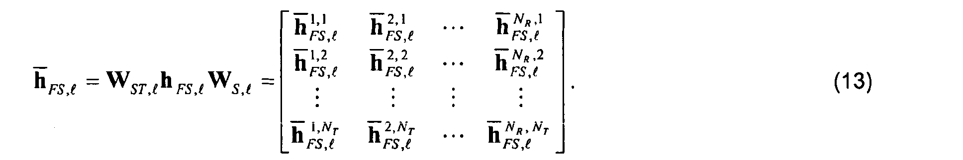
- the N T W ⁇ N T W spatial-temporal ( W ST ,l ) and the N R ⁇ N R spatial ( W S,l ) weighting matrices are computed and applied to the first-stage estimate h FS,l as:
- the W ⁇ 1 vector denotes the estimate h n R , n T / FS,l after the weighting processing.
- the weighting is performed to account for the spatial/temporal noise correlation and the non-orthogonality of the pilot sequences.
- the modal analysis is performed through the following operations.
- the l th space-time weighted estimate is first used to update the spatial and temporal correlation matrices: where 0 ⁇ ⁇ S ⁇ 1 and 0 ⁇ ⁇ T ⁇ 1 are exponential forgetting factors.
- the N T N R ⁇ r S doubly spatial modes U S,l are then calculated as the r S leading eigenvectors of the matrix (17), with 1 ⁇ r S ⁇ N T N R .
- the W ⁇ r T temporal modes U T,l are evaluated from the r T leading eigenvectors of the matrix (18), with 1 ⁇ r T ⁇ W .
- the corresponding channel modal components are given by where D S,l is a r S ⁇ r T matrix.
- Modal analysis allows the extraction from the unconstrained weighted channel estimate the only information really effective to the estimate, disregarding the useless one.
- the effective information is slow-varying (angles of departure, angles of arrival and delays) and result amplified by the updating process, to the detriment of fast-varying components that are cancelled.
- the matrix including the only channel modal components has reduced dimensions with respect to the matrix relevant to the full-dimensional weighted channel estimate.
- the weighted channel estimate is obtained through the modal synthesis: where is the weighted MA estimate for the channel between the n T th transmitting antenna and the n R th receiving antenna.
- Modal synthesis exploits the reduced-dimension modal matrix obtained in the preceding step to depress those elements of the full-dimensional weighted channel estimate matrix which don't match the values associated to the real spatial and temporal spread of the signal energy along the channel. As a consequence, the MSE of the re-estimated channel matrix is lower than the one of .
- Matrix is a refined weighted version of the first estimate .
- Step 5 Inverse weighting
- the N T N R ⁇ W matrix is rearranged into the N T W ⁇ N R matrix:
- the former weighting is cancelled from h MA,l by pre-multiplication with W -1 / ST,l and post-multiplication with W -1 / S,l :
- h MA,l W -1 ST,l h MA,l W -1 S,l
- This step acts on the re-estimated channel matrix h MA,l so as to restore the original correlations among the various components of the error that is exactly performed when weighting is implemented as the whitening step
- Matrix h MA,l is a refined version of the first estimate h FS,l .
- H n T , n R MA,l Fh n T , n R MA,l
Landscapes
- Engineering & Computer Science (AREA)
- Computer Networks & Wireless Communication (AREA)
- Signal Processing (AREA)
- Power Engineering (AREA)
- Physics & Mathematics (AREA)
- Mathematical Physics (AREA)
- Radio Transmission System (AREA)
Abstract
In a digital radio communication system a method is described of estimating
multiple channel response at the NR receiving antennas of a receiver connected to NT
transmitting antennas co-located with the transmitter. As a first step the Least Square
channel estimate ( h FS ,ℓ) is performed in the frequency domain, by transmitting OFDM
modulated pilot symbols univocally associated to the transmitting antennas, and using
relevant training pilots stored in the receiver. The LS estimate is noisy due to the
cumbersome number of parameters estimated. The method aims to reduce the complexity
of the unconstrained LS estimate by exploiting the hidden structure of the multipath time-varying
channel including NR×NT individual links. The LS estimate is spatially and
temporally weighted to decorrelate noise and interference (whitening) before to be
submitted to a modal filtering for reducing the initial complexity. Inverse weighting restores
the original correlation of the noise (de-whitening). Modal filtering includes spatial mode
identification, temporal mode identification, modal components estimation, and modal
synthesis. Modal filtering operates on doubly-spatial temporal domains (figure 6).
Description
- The present invention is referred to the field of the multicarrier communication systems, and more precisely to a method for the estimation and tracking of channel modes in a multicarrier communication system employing multiple NT co-located antennas at the transmitter and multiple NR co-located antennas at the receiver, in order to exploit transmitter and receiver diversity on the radio channel characterized by multiple paths, each described by slowly varying features (angles of departure, angles of arrival, delays, and fading correlation at transmitter and receiver) and a fast varying fading amplitude. The invention can be advantageously employed in the present single-user or multiuser radio communication systems, and also in future generation systems (e.g. 4G PLMNs) in which localized data transmissions assume prevailing importance (e.g. hot-spot).
- Fig.1 shows a scattering environment referred to a multiantenna system. The scattering environment is such that there are few rays from the transmitter to the receiver, each characterized by a direction of departure (DOD) α (T) / d and a direction of arrival (DOA) α (R) / d. This model is widely used for outdoor scenarios and has been presented for MIMO systems in technical literature. In fig.1 the transmitted signal is received after having undergone distortion due to the multipath propagation channel which make the channel frequency-selective and call for equalization at the receiver. Convenient implementation and robustness against frequency-selective fading channels are met by Orthogonal frequency division multiplexing (OFDM): a multicarrier modulation promising technique for high rate data transmission on a comb of densely spaced subchannels only subjected to flat fading. OFDM is susceptible to be employed with different schemes, especially for multiuser applications, e.g.: Multicarrier Code Division Multiple Access (MC-CDMA), Direct Sequence CDMA (DS-CDMA), Multitone CDMA (MT-CDMA), etc.. OFDM has already been standardized for a variety of radio applications, such as: digital audio broadcasting (DAB), digital television broadcasting (DVB), wireless local area networks (WLANs), and wideband radio access. In order to further increase the system skill in counteracting interferences and selective fading, OFDM can be combined with multiple antennas (see fig.1). As known, for properly detecting the information bits at the receiver side, it is necessary to recover knowledge of channel state information (CSI) from the received information stream. CSI can be acquired based on the transmission of training symbols that are a priori known at the receiver; blindly, i.e., relying only on the received symbols and exploiting statistical information and/or transmitted symbol properties (like finite alphabet, constant modulus, etc.); or making joint use of training symbols and information symbols on which hard or soft decision have been taken by the receiver (decision-directed-approach).
- A commonly used technique to this aim is known as the "Least Squares Estimation" (LSE). This techniques requires transmission of pilot symbols (training-based channel estimation). Optimisation of pilot symbols and their allocation in the frequency and time (i.e., over different OFDM symbols) is disclosed in the article of I. Barhumi et al., titled: "Optimum training design for MIMO in mobile wireless channels", IEEE Trans. Signal Proc., vol. 51, no. 6, pages 1615-1624, June 2003.
- Fig.2 shows an example of pilot arrangement across subcarriers and antennas, where the arrangement consists in using different pilot tones for different sources (4 antennas). In the example shown here each transmitting antenna transmits training symbols with fixed power over a frequency combination which is not used by other sources. The pilot tones of any combination are equally spaced along the frequencies, so that these combs not to overlap and interfere. Training data in fig.3 are sent once every N frames at a rate adjusted with respect to the variability of the channel, but in case of fast variability, training data can be sent every OFDM symbol indeed. All subcarriers in fig.3 not engaged with pilots are available to transmit data information. Alternatively, other arrangements are possible by choosing orthogonal signatures across the transmitting antennas as disclosed in Y.Li "Optimum training sequence for OFDM system with multiple transmit antennas" Proc. IEEE Globecom'00 Vol. 3, 27 Nov.-1 Dec. 2000, pp.1478 -1482.
- The performance of the LSE technique depends in a substantially inverse manner on the ratio between the number of parameters to be estimated and the number of pilot subcarriers employed for channel estimation. The accuracy of the estimate could be in principle improved by averaging over the estimates obtained in different OFDM symbols. This approach would lead to a remarkable reduction of the background Gaussian noise on the estimate but at the same time would result in an unacceptable distortion of the channel estimate, unless the propagation environment is characterized by very slow temporal variations.
- A different approach for channel estimation is based on the knowledge of the physics of the propagation channel. A method that builds on this idea for OFDM systems with a single antenna both at transmitter and receiver has been proposed in the article of B. Yang, K. B. Letaief, R. S. Cheng and Z. Cao, titled: "Channel estimation for OFDM transmission in multipath fading channels based on parametric channel modelling", IEEE Trans. Comm., vol. 49, no.3, pages 467-478, March 2001. It directly estimates the delays of the multipath and separately the corresponding fading amplitudes.
- An alternative solution able to avoid the direct estimation of those parameters is disclosed in patent application EP 02425260.3-A, filed in date 23rd April 2002 in the name of SIEMENS. The channel estimation operates in digital radio communication systems with the characteristics of GSM or UMTS, although extension to OFDM is vaguely indicated but not supported with sound arguments. In all effects the described solutions concerns single carriers accessed by Time Division Multiple Access (TDMA) or even TDMA-CDMA. The accessed carriers are digitally modulated by baseband bursts having a training sequence in position of midamble. The specific scenario which the citation is devoted to, foresees multiple antennas at the receiver and single antenna at the transmitters. A modal analysis of a preliminary unconstrained estimate of the channel in the spatial and temporal domain is performed a the receiver. The modal analysis is complete when identification of the channel components with respect to space and time modes has been attained. The estimate of space and time modes reduces to the solution of a quadratic problem, thus overcoming the problems of B. Yang et al. solution in terms of computational complexity and stability. Comparing the OFDM pilot tone layout in fig.2 with the training sequences used in TDMA or CDMA information bursts, it can be appreciated the great differences between the two approaches in channel estimation. More precisely, while in TDMA/CDMA training data are conveyed on a single modulated carrier, the OFDM training data are distributed among a plurality of subcarriers. Furthermore, while in the former case training data span a time window of several bit/chips, in the other case training data span the only symbol period. The highlighted differences together with the use of multiple transmitting antennas, unavoidably impact the channel estimation based on modal analysis.
- The main object of the present invention is that to indicate a method to perform channel estimation according to the modal analysis at the receivers of an OFDM-based radio communications system employing multiple co-located antennas both at the transmitters and the receivers.
- To achieve said objects the subject of the present invention is channel estimation method, as disclosed in the claims.
- Introductory arguments to the present invention is the observation that in multicarrier systems (in particular with mobile terminals) non-negligible fluctuations of the fading processes are expected between consecutive OFDM symbols (or even within each symbol) whereas the above mentioned slowly-varying parameters are constant over multiple symbols.
- According to the method of the invention, the channel estimation exploits the different varying rates of the multipath channel mentioned in the introduction. To this aim, following a first unconstrained channel estimation stage for the ensemble of NTNR temporal channels and arranging these estimates in a matrix form, a modal analysis/synthesis of the channel in the doubly-space and time domain is carried out. The modal analysis identifies the slowly-varying or stationary principal components of the channel related to the slow-variations of the corresponding physical parameters of multipath propagation (e.g., angles and/or spatial correlation of fading in the doubly-spatial domain and delays in the time domain) from the observation of multiple OFDM symbols. Notice that the term doubly-spatial domain refers to the way to account for the receiving and transmitting correlation properties across the antennas in a joint manner. Along with channel modes in doubly-space and time domain, temporal correlation of the fading processes can be regarded as a slowly-varying feature of the channel. As such, it is estimated from a multi-symbol frame of received signals. The fast-varying fading processes are tracked in the temporal domain, over consecutive OFDM symbols, by means of bayesian (e.g., Wiener or Kalman) or parametric (e.g., Maximum Likelihood, Least Squares) techniques. The first stage channel estimate is pre-processed by an appropriate weighting matrixes before being fed to the modal analysis/synthesis block. The weighting matrixes can be selected according to different criteria. The choice that minimizes the Mean Square Error (MSE) on the channel estimate is a whitening filter operating jointly in the spatial domain (for spatially correlated noise) and in the spatial-temporal domain (for pilot signals correlated in time and among the transmitting antennas). The above mentioned pre-processing is balanced by a corresponding operation at the output of the modal components tracker. The channel estimate for each user obtained from the multi-symbol modal analysis/synthesis and modal component tracker is interpolated over the entire bandwidth.
- In case the present invention is used in a MIMO system which allows multiuser access at the radio interface, such as PLMNs and WLANs, the available bandwidth is shared by all the active users, each of them employing in turn the multi-antenna transmitter. In order to perform equalization and decoding, the receiver has to obtain channel state information about all the users from the pilot subcarriers. Once the complete channel state is acquired, equalization is carried out by cancellation of inter-symbol interference (ISI) and/or multiuser interference (MUI).
- The features of the present invention which are considered to be novel are set forth with particularity in the appended claims. The invention, together with further objects and advantages thereof, may be understood with reference to the following detailed description of an embodiment thereof taken in conjunction with the accompanying drawings given for purely non-limiting explanatory purposes and wherein:
- fig.1, already described, shows a possible scattering scenario with multiantenna radio links;
- fig.2, already described, shows a possible known pilot arrangement across subcarriers and multiple transmitting antennas of an OFDM system;
- fig.3 shows the general architecture of an OFDM transmitter with multiple antennas;
- fig.4 shows the general architecture of an OFDM receiver with multiple antennas;
- fig.5 shows the internal structure of a Channel Estimator block of the OFDM receiver of fig.4;
- fig.6 shows the internal structure of a MA block (modal analyser/synthesizer) included in the Channel Estimator of fig.4.
- The non-limiting embodiment of the invention is referred to a single-user system for the only aim of not excessively complicate the already heavy notation. Nevertheless it is understood that the multiuser case is immediately derivable from the single user description. With reference to fig.1 we see an OFDM transmitter including an encoder of data to be transmitted, connected to a modulator which outputs symbols X ℓ to the input of a block Demux. The latter also receives multiple NT pilot symbols
X ℓ assigned to the transmission from NT antennas from a block Pilot-Mux and demultiplexes them and data symbols over NT outputs. The NT demultiplexed symbols X 1 / ℓ, X 2 / ℓ···X N T / ℓ are distributed over NT branches directed to respective blocks IDFT which perform the Inverse Discrete Fourier Transform. The NT streams at the output of IDFTs are sent to respective CP blocks for the insertion of a cyclic prefix CP and then are forwarded to an RF SECTION connected to the NT antennas. In operation, the encoder is a standard block, e.g. a convolutional encoder, that takes as input the information bit stream and adds redundancy in order to improve the performance of the link. The operation performed by the encoder is matched at the receiver by the corresponding decoder. The modulator performs the mapping of the encoded bits into generally complex symbols belonging to some constellation (such as 4-QAM). Pilot symbols are selected according to a pre-defined rule (known by the receiver). Multiplexing of data symbols (output by the modulator) and pilot symbols creates a unique stream by interleaving the two component streams. Demultiplexing on the NT substreams can be performed according to different criteria, see for instance fig.2. The NT substreams are divided into blocks of symbols of size K,to which Inverse Fast Fourier Transform (IDFT) is applied. The cyclic prefix CP is then added to the tail of the resulting blocks of dimension K. The CP contains the last W - 1 samples of the output of the IDFT block. The NT transmitted blocks in the frequency domain generally contain both data and pilot symbols. Pilot symbols are used at the receiver for channel estimation (training-based channel estimation). In particular, a subset of the available K subcarriers is employed for transmission of pilot symbols. We denote as
K the total number of pilot subcarriers per OFDM symbol (among those that contain pilots) divided by NT . The RF SECTION performs all the known operations for converting at IF the NT baseband streams and then to RF. The antenna power amplifiers are accurately linearized and dimensioned in such a way to be linear as in presence of the high Peak-to-Mean Envelope Power Ratio (PMEPR) characterizing OFDM. - With reference to fig.4 the OFDM receiver includes a RF SECTION connected to NR = NT antennas for receiving the radiofrequency signals and convers them to IF and then to baseband. The NR baseband streams reach respective S/P blocks to be parallel converted and forwarded to as many couple of cascaded blocks CP REMOV and FFT. The NR FFT blocks perform the Fast discrete Fourier Transform (FFT) and generates respective OFDM symbols complete with data and training information. The NR OFDM symbols simultaneously present at the output of FFT blocks are sent to the input of a Pilot/Data CP REMOV block which separates Pilot symbols
Y ℓ (Pilot) from data symbols Y ℓ (Data) and forwards the first ones to a Channel Estimator and the second ones to an Equalizer and Decoder blocks. The Channel Estimator also receives the pilot symbolsX ℓ stored in the receiver, so as it can calculate the noise covariance matrix and obtain the final channel estimates H MA,ℓ according to the modal analysis/synthesis method of the present invention, that will be detailed with reference to the successive figures. Both H MA,ℓ and Y ℓ (Data) reaches the inputs of the Equalizer and Decoder block to be used for channel equalisation and to obtain estimates of the transmitted OFDM symbols. A final P/S block performs parallel-to-serial conversion into a recovered bitstream forwarded to the application programs. Besides the (soft of hard valued) detected symbols Y and l (Data) are sent back to the Channel Estimator block, in case Decision-Directed (DD) channel estimate approach is accomplished. With this approach the unconstrained channel estimate can be obtained blindly by relying on the received symbols only and not pilots. The very general architecture of the OFDM multi-antenna receiver visible in fig.4 is known, but the invention is confined into the block Channel Estimator that will be detailed in the successive figures. - In operation, the samples received from each one of the NR receiving antennas are grouped in blocks of K + W - 1 samples, discarded the CP (i.e., the first W - 1 samples) and then applied to the FFT. The resulting signal Y n R / ℓ [k] received over the k th subcarrier (k = 1, 2, ... ,k) by the nR th receiving antenna in the ℓ th OFDM symbol can be written as:where: H nR ,nT / ℓ [k] is the channel gain for the link between the nT th transmitting antenna and the nR th receiving antenna over the k th subcarrier, X nT / ℓ [k] is the symbol transmitted by the nT th transmitting antenna over the k th subcarrier and N nR / ℓ [k] represents additive noise. Gathering the received signai over the K subcarriers in the K × 1 vector Y nR / ℓ = [Y n R / ℓ[0] Y nR / ℓ [1] ··· Y nR / ℓ [K - 1]] T it can be written that:
 with
with
- The operator diag(·) denotes a diagonal matrix with entries on the main diagonal given by its argument vector. The channel H n R ,n T / ℓ for the link between the nT th transmitting antenna and the nR th receiving antenna at the ℓ th OFDM symbol is obtained by applying the FFT to the corresponding W × 1 channel impulse response h n R ,n T / ℓ in the temporal domain. Hence H n R ,n T / ℓ = Fh n R ,n T / ℓ, where F is the K × W DFT matrix, with (m, n) entry given by
- In the following, the presentation focuses on the OFDM symbols containing pilots since the described method is a means to perform training-based channel estimation. Accordingly, the temporal index ℓ is assumed henceforth to run over the OFDM symbols containing pilots. The received signal over the pilot subcarriers can be collected in the
K N T × 1 vectorY n R / ℓ (it is assumedK ≥ W)where
X n T / ℓ is theK NT × 1 containing the pilot symbols for the nT th antenna andH n R ,n T / ℓ is theK NT × 1 gathering the corresponding channel gains. From (5), it isH n R ,n T / ℓ =F h n R ,n T / ℓ whereF is theK NT × W DFT matrix,Y n R / ℓ = Bℓh n R / ℓ +N n R / ℓ where: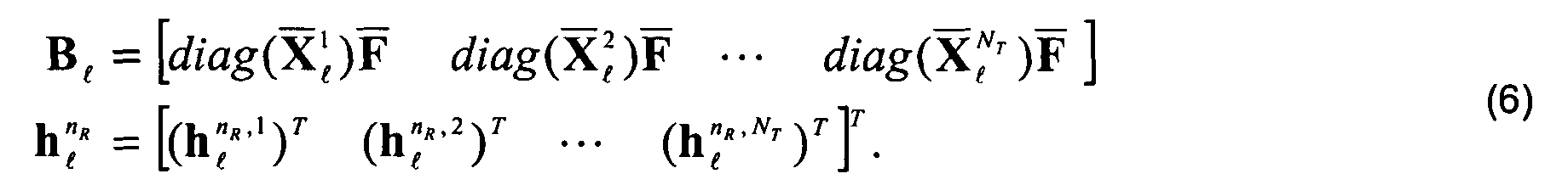
- The signal received by the NR antennas (5) can be collected in a NT
K × NR matrix:with the NTW × NR matrix h ℓ defined as and
and

- The Equalizer and Decoder block carries out the following action:
- tracks in the temporal domain, over consecutive OFDM symbols, the fast-varying fading processes for the aim of equalizing the amplitude of the received symbols. As previously said, this task is performed by means of bayesian (e.g., Wiener or Kalman) or parametric (e.g., Maximum Likelihood, Least Squares) techniques.
- Detects the transmitted symbols starting from the equalized signal and the knowledge of the modulation alphabet. The simplest schema of data detector is a filter matched to the estimate H MA,l , followed by a data decorrelator of known type. The reduced dimension of H MA,l strongly simplify data detection and improve the performance of the receiver.
- With reference to fig.5, we see that the CHANNEL ESTIMATOR block includes the cascade of the following blocks: FSE, SW, MA, IWE, and INT; another block named WEMC is not included in the cascade. FSE block at the top of the cascade receives symbols
Y ℓ and stored pilotsX ℓ and obtains in correspondence an unconstrained FSE estimate matrix h FS,ℓ. This is performed in known way. SymbolsY ℓ and stored pilotsX ℓ together with h FS,ℓ reach the input of WEMC which computes two weighting matrices W S and W ST , respectively, to be forwarded to the WE and IWE blocks. Block WE is weighting the estimating matrix h FS,ℓ for obtaining a matrix. The weighted estimate reaches the input of the MA blocks which performs modal analysis to detect doubly-spatial and temporal subspaces, at first, and then synthesizing a refined channel estimate
 by projecting the weighted estimate
 onto the two subspaces. The structured estimate
 is inverse weighted by the IWE block, obtaining at the output a structured matrix h MA,ℓ . Lastly, matrix h MA,ℓ is interpolated over the entire bandwidth by the interpolation block INT obtaining the final channel estimate H MA,l used by the Equalizer and Decoder block.
- With reference to fig.6, block MA of the preceding figure is further detailed. Inside block MA are visible four functional blocks, named: SMID, TMID MCES, and MDSYN. The first two blocks SMID and TMID perform the identification of Doubly Spatial and Temporal modes, respectively. Doubly Spatial analysis herein refers to the modal analysis carried out for a number of transmitting antennas NT ≥ 1 and a number of receiving antennas NR ≥ 1. The SMID and TMID blocks receive at the input the weighted estimateand obtain at the respective outputs two matrices U S,ℓ and U T,ℓ relevant to doubly spatial modes and temporal modes. These matrices are sent to the other two blocks MCES and MDSYN. The first one further receives the estimated matrix
 and calculates a matrix Dℓ , according to the expression reported in the figure, including the spatial and temporal modal components of the channel. Matrix D ℓ is forwarded to block MDSYNT which synthesises the structured matrix
 according to the expression reported in the figure.
- The operation of CHANNEL ESTIMATOR block depicted in figures 5 and 6 is described with particular care taken in the representation of matrices and vectors involved with the various blocks. As mentioned in the introduction, the propagation channel h n R ,n T / ℓ with nR = 1, 2,..., NR and nT = 1, 2,..., NT is characterized by multiple paths. Each of them is described by slowly varying features (angles of departure, angles of arrival and delays) and fast varying features (fading amplitudes). In the estimation of channel h n R ,n T / ℓ between the NT transmitting antennas and the NR receiving antennas, great importance assumes the modal analysis/synthesis (MA) of the so complicated channel. The description follows the sequential steps of the channel estimation method according to the present invention. The following main steps are included:
- 1. Full-dimensional channel estimation (unconstrained);
- 2. Weighting;
- 3. Modal analysis;
- 4. Modal Synthesis;
- 5. Inverse weighting;
- 6. Interpolation.
-
- The NTW × NR channel estimate:is obtained from the first stage estimator. Each W × 1 component:
 of the ensemble matrix h FS,ℓ represents the estimate for the channel over the link between the nT th transmitting antenna and the nR th receiving antenna. For
K ≥ W + NR / NT , the spatial noise covariance matrix can be estimated as well by:where 0 < µ < 1 is an exponential forgetting factor and * is the complex conjugate.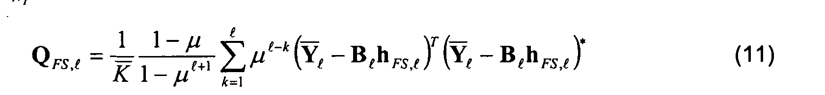
- The first stage estimator can be the conventional least square (LS) estimate
K NT ×K NT ) pseudo-inverse of B ℓ. - In receivers with iterative equalization and decoding, the first stage estimate h FS,ℓ can be obtained by exploiting both the pilot symbols and the (soft or hard valued) data symbols fedback by the decoder.
- The NTW × NTW spatial-temporal ( W ST,ℓ) and the NR × NR spatial (W S,ℓ ) weighting matrices are computed and applied to the first-stage estimate h FS,ℓ as:
- The W × 1 vectordenotes the estimate h n R ,n T / FS,ℓ after the weighting processing. The weighting is performed to account for the spatial/temporal noise correlation and the non-orthogonality of the pilot sequences. After weighting, the elements of {

h n R ,n T / FS,ℓ} for nR = 1,,NR and nT = 1,,NT are then arranged into the NTNR × W doubly-spatial-temporal matrix: to be fed to the modal analysis/synthesis block.
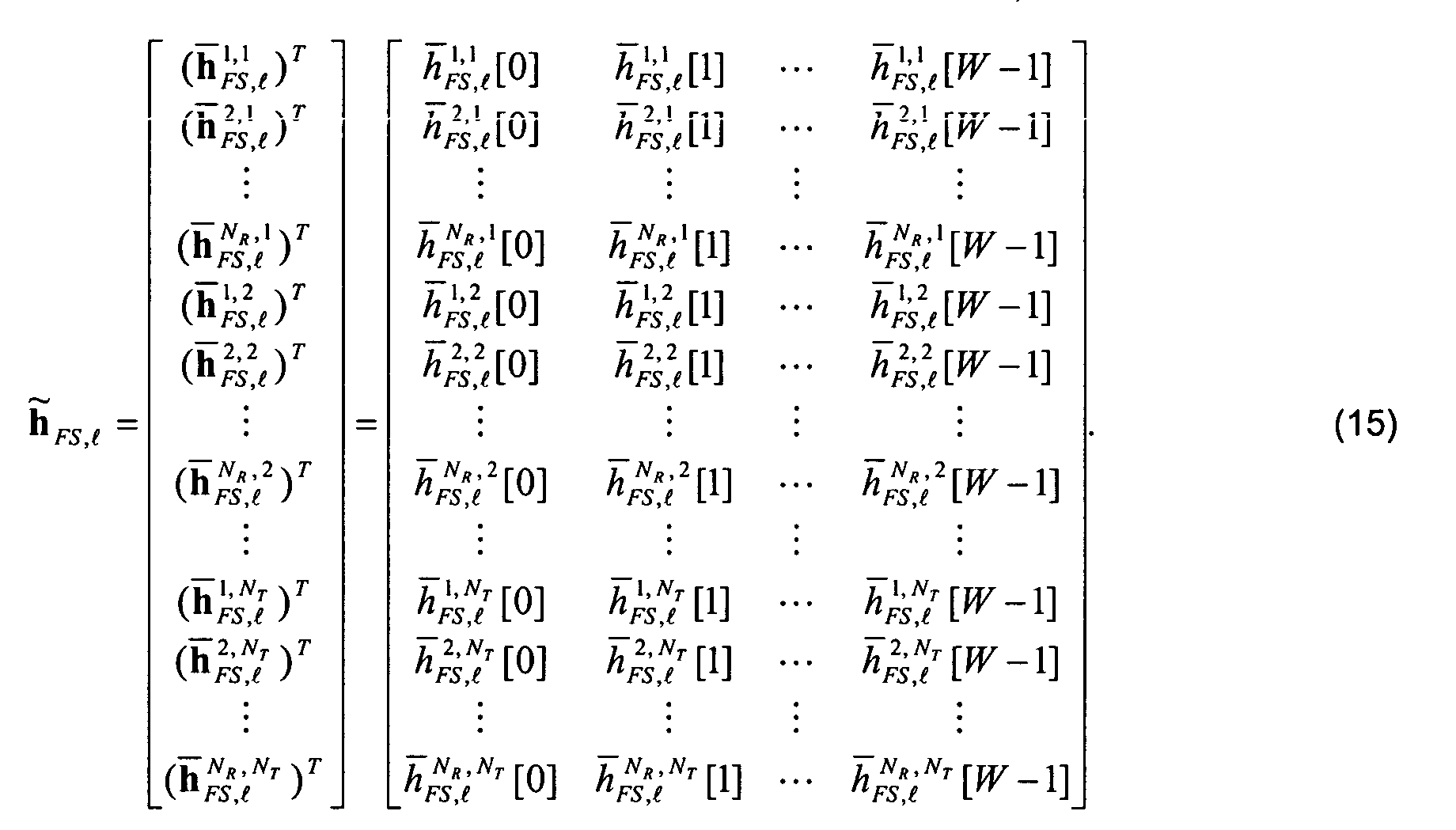
- The weighting matrices can be possibly chosen so as to whiten the error of the first
estimate h FS,ℓ ; for example:
where vec[

h FS,ℓ ] is the NTNRW × 1 vector obtained by stacking the columns of the matrixh FS,ℓ :the NTNR W × NTNR W matrix Cov[x] = E[(x - E[x])(x - E[ x ]) H ] is the covariance of the vector x = vec[
h FS,ℓ ] ; and E[·] means statistical expectation. Whitening the error of the first estimate h FS,ℓ means making the various contributions to the error reciprocally uncorrelated so as they resemble Additive White Gaussian Noise (AWGN). - The matrix W S,ℓ that fulfil (16) is evaluated based of the noise spatial covariance, that is estimated as in (11).
- The spatial weighting matrix can be chosen as W S,ℓ = I N
R for spatially white noise. - The weighting matrix can be chosen as W S,ℓ = Q -H/2 / FS,ℓ for spatially correlated noise.
- The matrix W ST,ℓ that fulfil (16) is evaluated based the noise temporal covariance and the pilot sequences correlation R b = B H / ℓB ℓ . The noise temporal covariance is estimated by a sample average.
- The spatial-temporal weighting matrix is set to W ST = I WN
T for temporally white noise and orthogonal pilot sequences. - The spatial-temporal weighting matrix can be chosen as
- For temporally correlated noise (or correlated noise in the frequency domain) with
temporal covariance (or frequency covariance) given by the W × W (or (
K NT ×K NT )) matrix Q T = E[N n R / ℓ(N n R / ℓ) H ] the first stage estimator can be the whitening least square (LS) estimatewhere and
and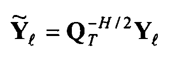 is the (
K NT ×K NT ) pseudo-inverse ofThe temporal whitening is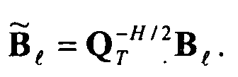

- The modal analysis is performed through the following operations. The ℓ th space-time weighted estimateis first used to update the spatial and temporal correlation matrices:

 where 0 < µ S < 1 and 0 < µ T < 1 are exponential forgetting factors. The NTNR × r S doubly spatial modes U S,ℓ are then calculated as the rS leading eigenvectors of the matrix (17), with 1 ≤ rS ≤ NTNR . Similarly, the W × rT temporal modes U T,ℓ are evaluated from the r T leading eigenvectors of the matrix (18), with 1 ≤ r T ≤ W. The corresponding channel modal components are given by
 where D S,ℓ is a rS × rT matrix. Modal analysis allows the extraction from the unconstrained weighted channel estimate
 the only information really effective to the estimate, disregarding the useless one. The effective information is slow-varying (angles of departure, angles of arrival and delays) and result amplified by the updating process, to the detriment of fast-varying components that are cancelled. As a consequence, the matrix including the only channel modal components has reduced dimensions with respect to the matrix
 relevant to the full-dimensional weighted channel estimate.
- The modal components D S,ℓ can be tracked over the OFDM symbols to improve the estimate performance. Standard tracking methods can be adopted, such as: Least-Mean-Square (LMS), Recursive Least-Square (RLS), or Kalman algorithm.
- The weighted channel estimateis obtained through the modal synthesis:
 where
where is the weighted MA estimate for the channel between the nT th transmitting antenna and the nR th receiving antenna. Modal synthesis exploits the reduced-dimension modal matrix obtained in the preceding step to depress those elements of the full-dimensional weighted channel estimate matrix
 which don't match the values associated to the real spatial and temporal spread of the signal energy along the channel. As a consequence, the MSE of the re-estimated channel matrix
 is lower than the one of
 . Matrix
 is a refined weighted version of the first estimate
 .
.
- The NTNR × W matrixis rearranged into the NTW × NR matrix:
 The former weighting is cancelled from
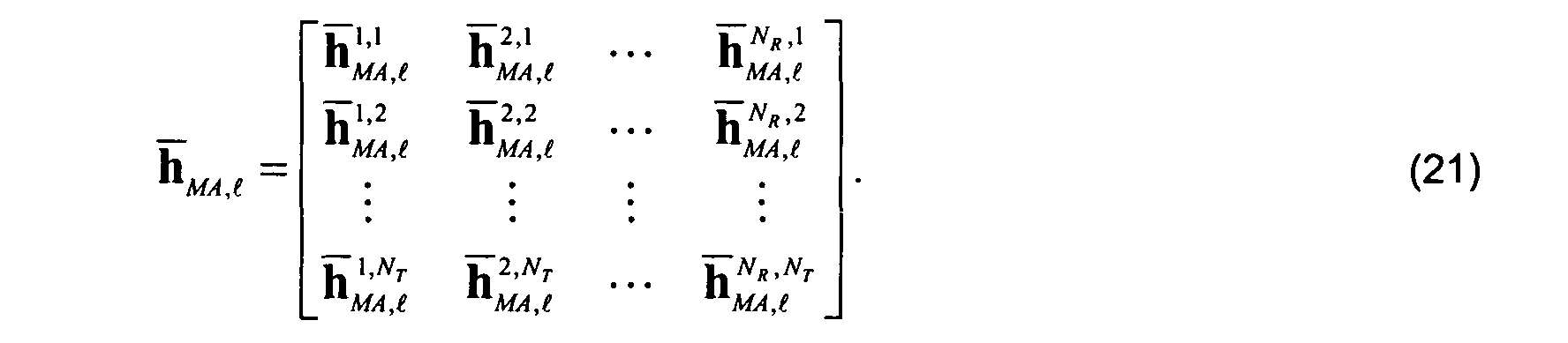
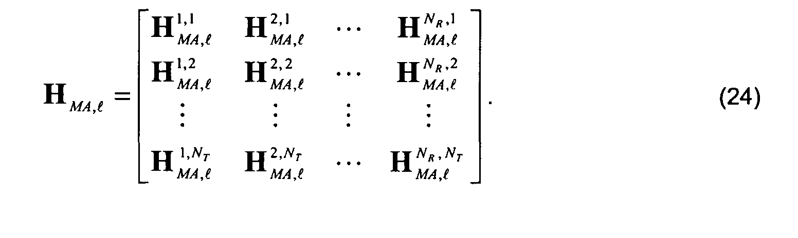
h MA,ℓ by pre-multiplication with W -1 / ST,ℓ and post-multiplication with W -1 / S,ℓ: - Each estimate h n T ,n R / MA,ℓ is interpolated over the entire bandwidth to get the K × 1 final estimate H n T ,n R / MA,ℓ in the frequency domain as:
- The overall KNT × NR estimate for the channel between the NT transmitting antennas and the NR receiving antennas is finally given by:
Claims (21)
- In a digital radio communication system a method of estimating channel response at a multiple MR-antenna receiver connected to more transmitting antennas sending modulated signals through a multipath time-varying channel, the method comprising the steps of:characterised in that:a) obtaining (FSE) an unconstrained channel estimate (
h FS,ℓ ) from the comparison between the received signals and training information stored in the receiver;b) spatial and temporal filtering (WE) the unconstrained channel estimate for whitening noise and interference elements;c) performing a modal analysis (MAE, SMID, TMID) over the whitened channel estimate () to identify the stationary spatial (U S,ℓ ) and temporal ( U T,ℓ ) modes of the channel; d) computing (MCES) the components (D ℓ ) of the whitened channel estimate along said spatial and/or temporal modes;e) performing a modal synthesis (MAE, MDSYN) to derive from said components a refined whitened channel estimate ();
 f) inverse filtering (IWE) the refined channel estimate for de-whitening,said unconstrained channel estimate (
h FS,ℓ ) is obtained upon transmitting from NT transmitting antennas co-located and cooperative at the transmitter side; andthe modal analysis/synthesis is carried jointly in the doubly-spatial and temporal domains. - The channel estimating method of the preceding claim, characterised in that said filtering the unconstrained channel estimate (
h FS,ℓ ) is obtained multiplying the channel estimate in matricial form by noise and interference weighting matrices (W S , W T ) operating a linear transformation towards sub-optimum estimate, including the whitening. - The channel estimating method of claim 2, characterised in that said spatial weighting is the whitening by the spatial noise covariance matrix (W S ).
- The channel estimating method of claim 2, characterised in that said spatial-temporal weighting is the whitening by the spatial-temporal correlation of the transmitted signals (W ST ).
- The channel estimating method of claim 2, characterised in that said spatial-temporal weighting is the whitening by the temporal correlation of the noise (W ST ).
- The channel estimating method of one of the preceding claims, characterised in that fast-variations into the NR×NT channels are estimated by tracking the corresponding modal components in the joint spatial and temporal domain.
- The channel estimating method of one of the preceding claims, characterised in that said unconstrained channel estimate (
h FS,ℓ ) is obtained in the frequency domain by transmitting OFDM modulated pilot symbols univocally associated to the transmitting antennas, and using relevant training pilots stored in the receiver. - The channel estimating method of the preceding claim, characterised in that modal analysis and synthesis optimises the channel response in frequency domain for the ensemble of NR×NT channels.
- The channel estimating method of the preceding claim, characterised in that said pilot OFDM symbols are either transmitted at symbol time or at multiple symbol time, according to the time-varying channel.
- The channel estimating method of one of the preceding claims, characterised in that said inverse filtered channel estimate (
h MA,ℓ ) is interpolated over the entire bandwidth of the OFDM modulated signals. - The channel estimating method of claim 9, characterised in that the weighting accounts for the non-orthogonality of the pilot symbols used by different transmitting antennas.
- The channel estimating method of claim 9, characterised in that the weighting is performed jointly in the spatial domain and in the temporal domain for temporally correlated noise and correlated pilot sequences.
- The channel estimating method of claim 9, characterised in that the weighting is performed by means of a spatial correlation matrix for temporally uncorrelated noise and orthogonal pilot sequences.
- The channel estimating method of one of the preceding claims, characterised in that the modal analysis is performed by estimating the channel modes from the doubly-spatial and temporal correlation matrices.
- The channel estimating method of claim 9, characterised in that the modal analysis includes updating the doubly-spatial and temporal modes by exploiting the weighted estimate derived within the current OFDM symbol.
- The channel estimating method of the preceding claim, characterised in that the updating of the doubly-spatial and temporal modes is carried out at a reduced rate compared to the OFDM symbols.
- The channel estimating method of the preceding claim, characterised in that the modal analysis includes tracking the channel components over the OFDM symbols.
- The channel estimating method of one of the the preceding claims, characterised in that the modal analysis/synthesis is carried out for temporal modes only.
- The channel estimating method of the preceding claim, characterised in that the tracking is carried out for the only temporal components over OFDM symbols.
- The channel estimating method of one of the preceding claims, characterised in that:the unconstrained channel estimate collects NR×NT channel responses into a unique description of the channel including transmission-side-spatial-related elements, reception-side-spatial-related elements, and temporal-related elements;said doubly-space mode analysis and synthesis exploits NR×NT correlations over the same numbers of channels from the antennas.
- The channel estimating method of claim 1, characterised in that said training information stored in the receiver correspond to already decided symbols.
Priority Applications (1)
| Application Number | Priority Date | Filing Date | Title |
|---|---|---|---|
| EP03425721A EP1530333A1 (en) | 2003-11-05 | 2003-11-05 | Method for channel estimation in a MIMO OFDM system |
Applications Claiming Priority (1)
| Application Number | Priority Date | Filing Date | Title |
|---|---|---|---|
| EP03425721A EP1530333A1 (en) | 2003-11-05 | 2003-11-05 | Method for channel estimation in a MIMO OFDM system |
Publications (1)
| Publication Number | Publication Date |
|---|---|
| EP1530333A1 true EP1530333A1 (en) | 2005-05-11 |
Family
ID=34429636
Family Applications (1)
| Application Number | Title | Priority Date | Filing Date |
|---|---|---|---|
| EP03425721A Withdrawn EP1530333A1 (en) | 2003-11-05 | 2003-11-05 | Method for channel estimation in a MIMO OFDM system |
Country Status (1)
| Country | Link |
|---|---|
| EP (1) | EP1530333A1 (en) |
Cited By (14)
| Publication number | Priority date | Publication date | Assignee | Title |
|---|---|---|---|---|
| EP1821445A1 (en) | 2006-02-16 | 2007-08-22 | Siemens S.p.A. | Method to improve the channel estimate in broadband simo/mimo cellular radio networks during abrupt interference variations |
| WO2007113390A1 (en) * | 2006-04-04 | 2007-10-11 | Nokia Corporation | Receiver and receiving method |
| WO2008129047A1 (en) * | 2007-04-23 | 2008-10-30 | Abilis Systems Sarl | Method for channel estimation in ofdm systems |
| WO2008140368A1 (en) * | 2007-05-09 | 2008-11-20 | Telefonaktiebolaget Lm Ericsson (Publ) | Receiver for a radio network and an method for determining a channel estimate for a radio channel |
| WO2009134177A1 (en) * | 2008-05-02 | 2009-11-05 | Telefonaktiebolaget L M Ericsson (Publ) | Joint estimation of mimo channels and noise correlation for wireless systems with multiple receive antennas |
| KR101313785B1 (en) * | 2005-10-28 | 2013-10-01 | 코닌클리케 필립스 일렉트로닉스 엔.브이. | Multiple antenna transmission with variable diversity gain |
| WO2014128369A1 (en) * | 2013-02-22 | 2014-08-28 | Cassidian Sas | Method for demodulating a signal |
| EP2852073A3 (en) * | 2009-02-04 | 2015-05-06 | Acorn Technologies, Inc. | Two-steps least squares time domain channel estimation for ofdm systems |
| TWI488454B (en) * | 2006-01-20 | 2015-06-11 | Qualcomm Inc | Method and apparatus for pilot multiplexing in a wireless communication system |
| US20150236872A1 (en) * | 2012-08-17 | 2015-08-20 | Zte Corporation | Method and device for estimating channel in muliple-receiving antenna system |
| US9225452B2 (en) | 2006-01-20 | 2015-12-29 | Qualcomm Incorporated | Method and apparatus for pilot multiplexing in a wireless communication system |
| US9762414B2 (en) | 2009-02-04 | 2017-09-12 | Acorn Technologies, Inc. | Least squares channel identification for OFDM Systems |
| CN112436872A (en) * | 2020-11-02 | 2021-03-02 | 北京邮电大学 | Multi-user large-scale MIMO channel estimation method and device |
| CN113219401A (en) * | 2021-04-09 | 2021-08-06 | 西安电子科技大学 | Signal direction of arrival estimation method under non-uniform noise background |
Citations (1)
| Publication number | Priority date | Publication date | Assignee | Title |
|---|---|---|---|---|
| EP1357714A1 (en) * | 2002-04-23 | 2003-10-29 | Siemens Information and Communication Networks S.p.A. | Method and device for channel estimation in digital radio communication systems |
-
2003
- 2003-11-05 EP EP03425721A patent/EP1530333A1/en not_active Withdrawn
Patent Citations (1)
| Publication number | Priority date | Publication date | Assignee | Title |
|---|---|---|---|---|
| EP1357714A1 (en) * | 2002-04-23 | 2003-10-29 | Siemens Information and Communication Networks S.p.A. | Method and device for channel estimation in digital radio communication systems |
Non-Patent Citations (2)
| Title |
|---|
| BARHUMI I ET AL: "Optimal training design for MIMO OFDM systems in mobile wireless channels", IEEE TRANSACTIONS ON SIGNAL PROCESSING, JUNE 2003, IEEE, USA, vol. 51, no. 6, June 2003 (2003-06-01), USA, pages 1615 - 1624, XP002284029, ISSN: 1053-587X * |
| JIANXUAN DU ET AL: "MIMO-OFDM channel estimation based on subspace tracking", 57TH IEEE SEMIANNUAL VEHICULAR TECHNOLOGY CONFERENCE. VTC 2003 (CAT. NO.03CH37431), 22 April 2003 (2003-04-22) - 25 April 2003 (2003-04-25), PISCATAWAY, NJ, USA, pages 1084 - 1088, XP002284030, ISBN: 0-7803-7757-5 * |
Cited By (28)
| Publication number | Priority date | Publication date | Assignee | Title |
|---|---|---|---|---|
| KR101313785B1 (en) * | 2005-10-28 | 2013-10-01 | 코닌클리케 필립스 일렉트로닉스 엔.브이. | Multiple antenna transmission with variable diversity gain |
| US9325404B2 (en) | 2005-10-28 | 2016-04-26 | Koninklijke Philips N.V. | Multiple antenna transmission with variable diversity gain |
| US9225452B2 (en) | 2006-01-20 | 2015-12-29 | Qualcomm Incorporated | Method and apparatus for pilot multiplexing in a wireless communication system |
| TWI488454B (en) * | 2006-01-20 | 2015-06-11 | Qualcomm Inc | Method and apparatus for pilot multiplexing in a wireless communication system |
| US7756007B2 (en) | 2006-02-16 | 2010-07-13 | Nokia Siemens Networks Gmbh & Co. Kg | Method to improve channel estimate in broadband SIMO/MIMO cellular radio networks during abrupt interference variations |
| CN101056286B (en) * | 2006-02-16 | 2012-09-12 | 西门子公司 | Method to improve the channel estimate in broadband SIMO/MIMO cellular radio networks during abrupt interference variations |
| WO2007093379A1 (en) * | 2006-02-16 | 2007-08-23 | Nokia Siemens Networks S.P.A. | Method to improve the channel estimate in broadband simo/mimo cellular radio networks during abrupt interference variations |
| EP1821445A1 (en) | 2006-02-16 | 2007-08-22 | Siemens S.p.A. | Method to improve the channel estimate in broadband simo/mimo cellular radio networks during abrupt interference variations |
| CN101416414B (en) * | 2006-04-04 | 2012-07-04 | 诺基亚公司 | Receiver and receiving method |
| KR100978779B1 (en) | 2006-04-04 | 2010-08-30 | 노키아 코포레이션 | Receiver and receiving method |
| JP2009532967A (en) * | 2006-04-04 | 2009-09-10 | ノキア コーポレイション | Receiver and receiving method |
| US7769117B2 (en) | 2006-04-04 | 2010-08-03 | Nokia Corporation | Determination of a noise covariance matrix for a wireless communication channel |
| WO2007113390A1 (en) * | 2006-04-04 | 2007-10-11 | Nokia Corporation | Receiver and receiving method |
| WO2008129047A1 (en) * | 2007-04-23 | 2008-10-30 | Abilis Systems Sarl | Method for channel estimation in ofdm systems |
| WO2008140368A1 (en) * | 2007-05-09 | 2008-11-20 | Telefonaktiebolaget Lm Ericsson (Publ) | Receiver for a radio network and an method for determining a channel estimate for a radio channel |
| EP2151107A4 (en) * | 2007-05-09 | 2016-12-28 | ERICSSON TELEFON AB L M (publ) | Receiver for a radio network and an method for determining a channel estimate for a radio channel |
| US8094762B2 (en) | 2008-05-02 | 2012-01-10 | Telefonaktiebolaget Lm Ericsson (Publ) | Joint estimation of MIMO channels and noise correlation for wireless systems with multiple receive antennas |
| WO2009134177A1 (en) * | 2008-05-02 | 2009-11-05 | Telefonaktiebolaget L M Ericsson (Publ) | Joint estimation of mimo channels and noise correlation for wireless systems with multiple receive antennas |
| US9762414B2 (en) | 2009-02-04 | 2017-09-12 | Acorn Technologies, Inc. | Least squares channel identification for OFDM Systems |
| EP2852073A3 (en) * | 2009-02-04 | 2015-05-06 | Acorn Technologies, Inc. | Two-steps least squares time domain channel estimation for ofdm systems |
| US9231788B2 (en) * | 2012-08-17 | 2016-01-05 | Zte Corporation | Method and device for estimating channel in multiple-receiving antenna system |
| US20150236872A1 (en) * | 2012-08-17 | 2015-08-20 | Zte Corporation | Method and device for estimating channel in muliple-receiving antenna system |
| US9391740B2 (en) | 2013-02-22 | 2016-07-12 | Airbus Ds Sas | Method for demodulating a signal |
| FR3002709A1 (en) * | 2013-02-22 | 2014-08-29 | Cassidian Sas | METHOD FOR DEMODULATING A SIGNAL |
| WO2014128369A1 (en) * | 2013-02-22 | 2014-08-28 | Cassidian Sas | Method for demodulating a signal |
| CN112436872A (en) * | 2020-11-02 | 2021-03-02 | 北京邮电大学 | Multi-user large-scale MIMO channel estimation method and device |
| CN112436872B (en) * | 2020-11-02 | 2021-09-14 | 北京邮电大学 | Multi-user large-scale MIMO channel estimation method and device |
| CN113219401A (en) * | 2021-04-09 | 2021-08-06 | 西安电子科技大学 | Signal direction of arrival estimation method under non-uniform noise background |
Similar Documents
| Publication | Publication Date | Title |
|---|---|---|
| Li | Simplified channel estimation for OFDM systems with multiple transmit antennas | |
| US7539259B2 (en) | OFDM channel estimation and tracking for multiple transmit antennas | |
| CA2341086C (en) | Clustered ofdm with channel estimation | |
| Gong et al. | Low complexity channel estimation for space-time coded wideband OFDM systems | |
| US7423961B2 (en) | Radio apparatus and adaptive array processing method | |
| US8351553B2 (en) | MIMO receiving apparatus and receiving method | |
| EP1821445A1 (en) | Method to improve the channel estimate in broadband simo/mimo cellular radio networks during abrupt interference variations | |
| EP1530333A1 (en) | Method for channel estimation in a MIMO OFDM system | |
| Gong et al. | Low rank channel estimation for space-time coded wideband OFDM systems | |
| Ganesh et al. | Channel estimation analysis in MIMO-OFDM wireless systems | |
| US7619964B2 (en) | High doppler channel estimation for OFD multiple antenna systems | |
| KR20070024310A (en) | Interference cancellation method and module for ofdma mobile communication system | |
| KR20080087254A (en) | Method and system for transmitting/receiving data in a communication system | |
| Wang et al. | Performance of linear interpolation-based MIMO detection for MIMO-OFDM systems | |
| Li et al. | Alamouti space time coded OFDM for underwater acoustic channels | |
| Du et al. | Adaptive blind channel identification and equalization for OFDM-MIMO wireless communication systems | |
| Farouk et al. | Channel estimation for MIMO-OFDM systems based on data nulling superimposed pilots | |
| Pham et al. | Channel information estimation and data detection for MIMO-OFDM systems under unknown narrowband interference | |
| Shao et al. | Study of Channel Estimation Algorithms for Large-Scale Multiple-Antenna Systems using 1-Bit ADCs and Oversampling | |
| Zheng et al. | Improved frequency-domain channel estimation for fast time-varying MIMO-SCFDE channels | |
| Karnani et al. | Enhancement of Oversampling Scheme to Achieve Diversity Gain in Wireless Communication by Feedback Equalization Algorithm | |
| Siddiqui et al. | PIC assisted IBDFE based iterative spatial channel estimation with intra and inter-cell interference in SC-FDE system | |
| Peng et al. | Blind beamforming for CCI reduction by kurtosis maximization for OFDM systems in multipath | |
| Li et al. | A novel fractionally spaced frequency domain equalization scheme for single carrier cyclic prefix assisted MIMO-CDMA systems | |
| KR101019172B1 (en) | Apparatus and method for data transmission/receiving in an v-blast orthogonal frequency division multiple system |
Legal Events
| Date | Code | Title | Description |
|---|---|---|---|
| PUAI | Public reference made under article 153(3) epc to a published international application that has entered the european phase |
Free format text: ORIGINAL CODE: 0009012 |
|
| AK | Designated contracting states |
Kind code of ref document: A1 Designated state(s): AT BE BG CH CY CZ DE DK EE ES FI FR GB GR HU IE IT LI LU MC NL PT RO SE SI SK TR |
|
| AX | Request for extension of the european patent |
Extension state: AL LT LV MK |
|
| AKX | Designation fees paid | ||
| STAA | Information on the status of an ep patent application or granted ep patent |
Free format text: STATUS: THE APPLICATION IS DEEMED TO BE WITHDRAWN |
|
| 18D | Application deemed to be withdrawn |
Effective date: 20051112 |
|
| REG | Reference to a national code |
Ref country code: DE Ref legal event code: 8566 |