EP1525430B1 - Procede pour determiner la vitesse du son dans un materiau de base, en particulier pour mesurer une epaisseur de paroi - Google Patents
Procede pour determiner la vitesse du son dans un materiau de base, en particulier pour mesurer une epaisseur de paroi Download PDFInfo
- Publication number
- EP1525430B1 EP1525430B1 EP03787614A EP03787614A EP1525430B1 EP 1525430 B1 EP1525430 B1 EP 1525430B1 EP 03787614 A EP03787614 A EP 03787614A EP 03787614 A EP03787614 A EP 03787614A EP 1525430 B1 EP1525430 B1 EP 1525430B1
- Authority
- EP
- European Patent Office
- Prior art keywords
- base material
- sound
- transducer
- coupling surface
- sound velocity
- Prior art date
- Legal status (The legal status is an assumption and is not a legal conclusion. Google has not performed a legal analysis and makes no representation as to the accuracy of the status listed.)
- Expired - Lifetime
Links
Images

Classifications
-
- G—PHYSICS
- G01—MEASURING; TESTING
- G01N—INVESTIGATING OR ANALYSING MATERIALS BY DETERMINING THEIR CHEMICAL OR PHYSICAL PROPERTIES
- G01N29/00—Investigating or analysing materials by the use of ultrasonic, sonic or infrasonic waves; Visualisation of the interior of objects by transmitting ultrasonic or sonic waves through the object
- G01N29/04—Analysing solids
- G01N29/041—Analysing solids on the surface of the material, e.g. using Lamb, Rayleigh or shear waves
-
- G—PHYSICS
- G01—MEASURING; TESTING
- G01B—MEASURING LENGTH, THICKNESS OR SIMILAR LINEAR DIMENSIONS; MEASURING ANGLES; MEASURING AREAS; MEASURING IRREGULARITIES OF SURFACES OR CONTOURS
- G01B17/00—Measuring arrangements characterised by the use of infrasonic, sonic or ultrasonic vibrations
- G01B17/02—Measuring arrangements characterised by the use of infrasonic, sonic or ultrasonic vibrations for measuring thickness
- G01B17/025—Measuring arrangements characterised by the use of infrasonic, sonic or ultrasonic vibrations for measuring thickness for measuring thickness of coating
-
- G—PHYSICS
- G01—MEASURING; TESTING
- G01N—INVESTIGATING OR ANALYSING MATERIALS BY DETERMINING THEIR CHEMICAL OR PHYSICAL PROPERTIES
- G01N29/00—Investigating or analysing materials by the use of ultrasonic, sonic or infrasonic waves; Visualisation of the interior of objects by transmitting ultrasonic or sonic waves through the object
- G01N29/04—Analysing solids
- G01N29/07—Analysing solids by measuring propagation velocity or propagation time of acoustic waves
-
- G—PHYSICS
- G01—MEASURING; TESTING
- G01N—INVESTIGATING OR ANALYSING MATERIALS BY DETERMINING THEIR CHEMICAL OR PHYSICAL PROPERTIES
- G01N29/00—Investigating or analysing materials by the use of ultrasonic, sonic or infrasonic waves; Visualisation of the interior of objects by transmitting ultrasonic or sonic waves through the object
- G01N29/44—Processing the detected response signal, e.g. electronic circuits specially adapted therefor
- G01N29/4472—Mathematical theories or simulation
-
- G—PHYSICS
- G01—MEASURING; TESTING
- G01N—INVESTIGATING OR ANALYSING MATERIALS BY DETERMINING THEIR CHEMICAL OR PHYSICAL PROPERTIES
- G01N2291/00—Indexing codes associated with group G01N29/00
- G01N2291/02—Indexing codes associated with the analysed material
- G01N2291/028—Material parameters
- G01N2291/02854—Length, thickness
-
- G—PHYSICS
- G01—MEASURING; TESTING
- G01N—INVESTIGATING OR ANALYSING MATERIALS BY DETERMINING THEIR CHEMICAL OR PHYSICAL PROPERTIES
- G01N2291/00—Indexing codes associated with group G01N29/00
- G01N2291/04—Wave modes and trajectories
- G01N2291/042—Wave modes
- G01N2291/0421—Longitudinal waves
-
- G—PHYSICS
- G01—MEASURING; TESTING
- G01N—INVESTIGATING OR ANALYSING MATERIALS BY DETERMINING THEIR CHEMICAL OR PHYSICAL PROPERTIES
- G01N2291/00—Indexing codes associated with group G01N29/00
- G01N2291/04—Wave modes and trajectories
- G01N2291/057—Angular incidence, parallel to surface propagation
Definitions
- the invention relates to a method for determining the speed of sound Cb in a base material using an ultrasonic probe having a transmitting oscillator, a receiving oscillator and a leading body, wherein the leading body a) has a coupling surface with which the probe can be coupled to the base material, b) receives the receiving oscillator and the transmitting oscillator and c) has a speed of sound Cv, the transmitting oscillator and the receiving oscillator are aligned obliquely to each other and obliquely to the coupling surface at an entrance angle, so that a main transmitter direction of the transmitting oscillator and a main receiving direction of the receiving oscillator intersect below the coupling surface, Send oscillator and receiving oscillators have a center distance K from each other, the transmitting oscillator has a center distance Ds from the coupling surface and the receiving oscillator has a distance De from the coupling surface, in which method an Ultrasc hallimpuls is generated by the transmitting oscillator, runs through the
- the determination of the speed of sound Cb is a prerequisite for being able to determine the wall thickness of the base material.
- this method requires sufficiently reflective and smooth surfaces, in particular a sufficiently smooth back surface, so that multiple back and forth comes in the base material. With rough back surfaces, this method can not be used, but one is reliant on a one-off back and forth. The wall thickness can then be determined via the speed of sound Cb.
- the achievement of the invention is to have recognized that the detection of the shortest transit time Ttot of the ultrasonic pulse and an optimization of all possible sound paths to that sound path that provides the shortest total time as a function of Cb, a precise statement about the speed of sound Cb in Basic material supplies.
- the invention Thus, the actual paths underlying a sound pulse are based. She makes no assumptions about the way, as in the US 6,035,717 A the case is. The errors of this prior art measuring method and the corresponding device are therefore avoided according to the invention.
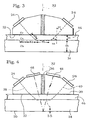
- This test head has a specially shaped, substantially prismatic flow body 20.
- This has a flat coupling surface 22, also called active surface and this opposite chamfers on which a transmitting oscillator 24 and a receiving oscillator 26 are held, in particular are cemented.
- Both oscillators 24, 26 are identical. They are oblique to each other and also obliquely to the coupling surface 22nd arranged. This arrangement will be discussed in more detail below.
- a perpendicular bisector ie a line running at right angles to the contact surface of the oscillator with the lead body 20 and through the center of this contact surface of the oscillator extends at a certain angle to the coupling surface 22, this angle is (90 ° - ⁇ v ) and is for both oscillators 24, 26 alike. Furthermore, the respective mid-perpendiculars lie in the same plane, namely in the plane of Fig. 1 ,
- the two oscillators 24, 26 are arranged in a symmetrical manner with respect to a symmetry plane 32. They are placed obliquely to the coupling surface 22, that in a base material 34, to which the flow body 20 is coupled via suitable means known per se, a surface wave 35 is generated, which will be discussed in detail.
- a separating layer 36 provided substantially along the plane of symmetry 3 2 ensures that a direct cross-talk between transmitting oscillator 24 and receiving oscillator 26 is prevented.
- the specified perpendicular bisectors usually coincide with a main beam, that is to say a main transmitting beam 38 and a main receiving beam 40.
- the speed Schallge Cv in the flow body 20 is known. Finally, the distance K between the surface centers of the two oscillators 24, 26. Finally, the distance of the centroid of the transmission oscillator 24 of the coupling surface 22 and the distance of the center of the receiving oscillator 26 of the coupling surface 22 are determinable and thus known. Due to the symmetry both have the value Dv. With the help of only these specifications, it is now possible, the sound velocity Cb in the base material 34. In a further step, it is then possible to determine the thickness, that is to say the wall thickness Db of the base material 34.
- the shortest path of a sound pulse from the transmitter oscillator 24 to the receiver oscillator 26 is as follows: The pulse travels along the main transmit beam, then as the surface wave 35 in the base material 34 and finally along again of the main receive beam 40 into the receive oscillator 26. This path is in Fig. 1 dashed lines, it runs along the main transmit beam 38 and the main receive beam 40th
- the running distance Sb of the surface wave 35 is a function of the speed of sound Cb in the base material 34 and also depends on the constant quantities K, Cv and Dv.
- the speed of sound Cb in the base material 34 is obtained by optimizing the associated sound travel path. So it's the sound running way which provides the shortest total time Ttot as a function of the speed of sound Cb to be determined.
- the respective path taken by the sound pulse with the shortest total transit time Ttot is thus a function of the speed of sound Cb and also dependent on the known values K, Dv and Cv.
- the different center point distances of the transmitting oscillator 24 and the receiving oscillator 26 must be taken into account by the coupling surface 22.
- the ultrasound propagates from the transmitting oscillator 24 over a first path Sv to the base material 34, for which he needs the time Tv. There, a creeping wave 35 is generated. She has the in FIG. 2 given length Sb. This length is traversed in the time Tb. From the creeping wave, a portion reaches the receiving oscillator 26 via a path which, due to the symmetry, has the length Sv and for which the time Tv is required.
- An ultrasonic pulse emitted by the transmitting oscillator 24 causes not only a surface wave 35 in the base material 34 but also further waves, the longitudinal surface wave 35 has the shortest running distance and also the shortest total running time Ttot.
- T dead K C b + 2 ⁇ D v ⁇ 1 C v cos arcsin C v C b - tan arcsin C v C b C b ; 9 / 12
- FIG. 3 shows the arrangement of the preceding figures, but now there is additionally a layer 46, a so-called coating on the base material 34.
- This layer has a thickness Ds. It should be determined by the speed of sound Cs of the layer. Since this too is unknown, the sound velocity is again determined as before.
- FIG. 3 again shows only the sound path with the shortest total time Ttot.
- a surface wave is generated, but this is scheduled to arrive after the surface wave 35 in the base material 34.
- the base material is typically a metal
- the sound velocities are at 4500 to 7000 m / s.
- the layer 46 is typically a plastic, a paint, and the like, and the sonic velocities are typically 2000 to 3000 ms.
- the layer 46 is a metal coating on a plastic base material
- the layer is made of a higher sound velocity metal than the base material, e.g. B. Coating in Ag, base material in Au, must be worked according to the preceding considerations by simply layer 46 is used as the base material.
- FIG. 3 shown Schalllaufweg as the shortest path considered.
- the entrance angle ⁇ v is changed in the layer 4 6 to ⁇ s.
- the running distances in the volume of the layer 46 result FIG. 3 they are Ss.
- the associated sound propagation time is Ts.
- T dead 2 ⁇ T v + T s + T b ;
- C v S v T v ;
- T v S v C v ;
- cos ⁇ v D v S v ;
- ⁇ S v D v cos ⁇ v ;
- T v D v C v cos ⁇ v ; 17 / 18
- T s D s C s cos ⁇ s ; 19
- T b S b C b ;
- S b K - 2 ⁇ K b + K s ;
- tan ⁇ v K s D v ;
- ⁇ K s D v tan ⁇ v ;
- tan ⁇ s K b D s ;
- ⁇ K b D s tan ⁇ s ;
- S b K - 2 ⁇ D s tan ⁇ s + D v tan ⁇ v ; 22 / 23 / 24
- T b K - 2 ⁇ D s tan ⁇ s + D v tan ⁇ v C b ; 21 / 25
- T dead 2 ⁇ D v C v cos ⁇ v + D s C s cos ⁇ s + K - 2 ⁇ D s tan ⁇ s + D v tan ⁇ v C b ; 16 / 19 / 20 / 26
- T dead 2 ⁇ D v C v cos ⁇ v + 2 ⁇ D s C s cos ⁇ s + K C b - 2 ⁇ D s tan ⁇ s C b - 2 ⁇ D v tan ⁇ v C b ;
- T dead K C b + 2 ⁇ D v ⁇ 1 C v cos ⁇ v - tan ⁇ v C b + D s ⁇ 1 C s cos ⁇ s - tan ⁇ s C b ;
- T dead ⁇ v ⁇ s K C b + 2 ⁇ f 1 ⁇ v + f 2 ⁇ s ; 29
- the shortest total running time Ttot can be measured by means of a suitable measuring instrument, for example the Applicant's DMS 2 device.
- the thickness Ds of the layer 46 and / or the thickness Db of the base material 34 can now be determined via them if the speeds of sound Cs and Cb are known. Thus, one can determine Cb at an uncoated point of the specimen with the aid of (27).
- a second, subsequent echo is obtained from a back wall 50 of the base material 34. From the time difference between the two echoes and the previously measured sound velocity Cb in the base material 34, its thickness Db can be determined. However, the thickness Db can also be obtained as the difference between this echo of the rear wall 50 and the entrance echo, taking into account the speeds of sound, minus the thickness Ds of the layer 46.
Landscapes
- Physics & Mathematics (AREA)
- General Physics & Mathematics (AREA)
- Pathology (AREA)
- Health & Medical Sciences (AREA)
- Life Sciences & Earth Sciences (AREA)
- Chemical & Material Sciences (AREA)
- Analytical Chemistry (AREA)
- Biochemistry (AREA)
- General Health & Medical Sciences (AREA)
- Immunology (AREA)
- Acoustics & Sound (AREA)
- Algebra (AREA)
- Mathematical Analysis (AREA)
- Mathematical Optimization (AREA)
- Mathematical Physics (AREA)
- Pure & Applied Mathematics (AREA)
- Engineering & Computer Science (AREA)
- Signal Processing (AREA)
- Investigating Or Analyzing Materials By The Use Of Ultrasonic Waves (AREA)
- Length Measuring Devices Characterised By Use Of Acoustic Means (AREA)
Abstract
Claims (6)
- Procédé de détermination de la vitesse du son Cb dans un matériau de base (34) en utilisant un palpeur à ultrasons qui comprend un oscillateur émetteur (24), un oscillateur récepteur (26) et un corps de couplage (20), ledit corps de couplage (20) a) comprenant une surface de couplage (22) par laquelle ledit palpeur peut être couplé au matériau de base (34), b) recevant ledit oscillateur récepteur (26) ainsi que ledit oscillateur émetteur (24) et c) présentant une vitesse du son Cv, ledit oscillateur émetteur (24) et ledit oscillateur récepteur (26) étant orientés respectivement obliquement l'un par rapport à l'autre et obliquement par rapport à ladite surface de couplage (22) sous un angle d'entrée (αv) de sorte qu'une direction principale d'émission de l'oscillateur émetteur (24) et une direction principale de réception de l'oscillateur récepteur se coupent au-dessous de la surface de couplage (22), ledit oscillateur émetteur (24) et ledit oscillateur récepteur (26) présentant un entraxe K l'un par rapport à l'autre, ledit oscillateur émetteur (24) et ledit oscillateur récepteur (26) présentant un entraxe Dv par rapport à la surface de couplage (22), procédé dans lequel une impulsion ultrasonore est générée par ledit oscillateur émetteur (24), traverse ledit corps de couplage (20) et entre dans le matériau de base (34) où elle provoque une onde de cheminement (35) et une partie de celle-ci atteint ledit oscillateur récepteur (26) en passant par ledit corps de couplage (22), caractérisé par le fait que l'on mesure le plus court temps de propagation du son Ttot qui se présente dans le cas de trajectoires différentes du son se distinguant les une des autres en terme d'angle d'entrée (αv), et on détermine la vitesse du son Cb dans le matériau de base (34) sur celui des chemins entre l'oscillateur émetteur (24) et l'oscillateur récepteur, qui fournit le plus court temps total de propagation Ttot.
- Procédé selon la revendication, 1, caractérisé par le fait que ledit chemin qui fournit le plus court temps total de propagation Ttot est déterminé en additionnant la trajectoire de propagation depuis l'oscillateur émetteur (24) jusqu'au matériau de base (34), la trajectoire de propagation dans ledit matériau de base (34) ainsi que la trajectoire de propagation depuis le matériau de base (34) jusqu'à l'oscillateur récepteur (26) et en optimisant ces trajectoires de propagation quant au plus court temps total de propagation Ttot, en particulier en différenciant selon ledit angle d'entrée (αv).
- Procédé selon la revendication 1, caractérisé par le fait que le plus court temps total de propagation Ttot est obtenu par

- Procédé selon la revendication 1, caractérisé par le fait que ledit oscillateur émetteur (24) et ledit oscillateur récepteur (26) sont de construction identique, que leurs rayons principaux (38, 40) sont situés dans le même plan et que leurs rayons principaux (38, 40) s'étendent au même angle d'entrée (αv) par rapport à ladite surface de couplage (22).
- Procédé de détermination de la vitesse du son dans un matériau de revêtement qui est présente en tant que couche (46) sur le matériau de base (34), procédé dans lequel, d'abord, la vitesse du son Cb dans ledit matériau de base (34) est déterminée selon la revendication 1 et, ensuite, le palpeur est posé sur ladite couche (46) qui présente une épaisseur Ds, une impulsion ultrasonore est générée par ledit oscillateur émetteur (24), qui traverse - obliquement par rapport à ladite surface de couplage (22) - aussi bien le corps de couplage (20) que la couche (46), provoque une onde de cheminement dans le matériau de base (34) et atteint, en tant que partie de celle-ci, à nouveau et obliquement par rapport à la surface de couplage, ledit oscillateur récepteur (26), en passant par ladite couche (46) et par ledit corps de couplage (20), que le signal de réception avec le plus court temps total de propagation Ttot est saisi et mesuré et que l'épaisseur Ds de la couche (46) est déterminée à partir du chemin qui fournit le plus court temps total de propagation Ttot.
- Procédé de détermination de la vitesse du son Cs dans un matériau de revêtement selon la revendication 5, caractérisé par le fait que le plus court temps total de propagation Ttot est obtenu par

avec Ds = épaisseur de la couche.
Applications Claiming Priority (5)
| Application Number | Priority Date | Filing Date | Title |
|---|---|---|---|
| DE10232475 | 2002-07-17 | ||
| DE10232475 | 2002-07-17 | ||
| DE10327102A DE10327102A1 (de) | 2002-07-17 | 2003-06-12 | Verfahren zur Bestimmung der Schallgeschwindigkeit in einem Basismaterial, insbesondere für eine Wanddickenmessung |
| DE10327102 | 2003-06-12 | ||
| PCT/DE2003/002150 WO2004017021A2 (fr) | 2002-07-17 | 2003-06-27 | Procede pour determiner la vitesse du son dans un materiau de base, en particulier pour mesurer une epaisseur de paroi |
Publications (2)
| Publication Number | Publication Date |
|---|---|
| EP1525430A2 EP1525430A2 (fr) | 2005-04-27 |
| EP1525430B1 true EP1525430B1 (fr) | 2011-06-15 |
Family
ID=31889076
Family Applications (1)
| Application Number | Title | Priority Date | Filing Date |
|---|---|---|---|
| EP03787614A Expired - Lifetime EP1525430B1 (fr) | 2002-07-17 | 2003-06-27 | Procede pour determiner la vitesse du son dans un materiau de base, en particulier pour mesurer une epaisseur de paroi |
Country Status (5)
| Country | Link |
|---|---|
| US (1) | US7415880B2 (fr) |
| EP (1) | EP1525430B1 (fr) |
| AU (1) | AU2003250276A1 (fr) |
| CA (1) | CA2492177C (fr) |
| WO (1) | WO2004017021A2 (fr) |
Cited By (1)
| Publication number | Priority date | Publication date | Assignee | Title |
|---|---|---|---|---|
| CN105044215A (zh) * | 2015-07-10 | 2015-11-11 | 国网天津市电力公司 | 一种非破坏性的材料声速现场测量方法 |
Families Citing this family (28)
| Publication number | Priority date | Publication date | Assignee | Title |
|---|---|---|---|---|
| AT524895A1 (de) * | 2021-03-24 | 2022-10-15 | Ac2T Res Gmbh | Vorrichtung zur Bestimmung chemisch-physikalischer Eigenschaften in einem tribologischen System |
| US7762136B2 (en) * | 2005-11-07 | 2010-07-27 | Georgia Tech Research Corporation | Ultrasound systems and method for measuring weld penetration depth in real time and off line |
| EP2088932B1 (fr) | 2006-10-25 | 2020-04-08 | Maui Imaging, Inc. | Procédé et appareil de production d'images ultrasonores au moyen d'une pluralité d'orifices |
| US9788813B2 (en) | 2010-10-13 | 2017-10-17 | Maui Imaging, Inc. | Multiple aperture probe internal apparatus and cable assemblies |
| US9282945B2 (en) | 2009-04-14 | 2016-03-15 | Maui Imaging, Inc. | Calibration of ultrasound probes |
| US10226234B2 (en) | 2011-12-01 | 2019-03-12 | Maui Imaging, Inc. | Motion detection using ping-based and multiple aperture doppler ultrasound |
| US8602993B2 (en) | 2008-08-08 | 2013-12-10 | Maui Imaging, Inc. | Imaging with multiple aperture medical ultrasound and synchronization of add-on systems |
| DE102008041835A1 (de) * | 2008-09-05 | 2010-03-18 | Ge Inspection Technologies Gmbh | Impulsechoverfahren mittels Gruppenstrahler und Temperaturkompensation |
| KR101659723B1 (ko) * | 2009-04-14 | 2016-09-26 | 마우이 이미징, 인코포레이티드 | 복수 개구 초음파 어레이 정렬 설비 |
| US8286488B2 (en) * | 2009-05-01 | 2012-10-16 | General Electric Company | Apparatus and system for measuring material thickness |
| WO2011103303A2 (fr) | 2010-02-18 | 2011-08-25 | Maui Imaging, Inc. | Transmission à source ponctuelle et correction de la vitesse du son à l'aide d'une imagerie par ultrasons à ouvertures multiples |
| US9668714B2 (en) | 2010-04-14 | 2017-06-06 | Maui Imaging, Inc. | Systems and methods for improving ultrasound image quality by applying weighting factors |
| EP3563768A3 (fr) | 2010-10-13 | 2020-02-12 | Maui Imaging, Inc. | Transducteurs à ultrasons concaves et réseaux 3d |
| KR20140107648A (ko) | 2011-12-29 | 2014-09-04 | 마우이 이미징, 인코포레이티드 | 임의의 경로들의 m-모드 초음파 이미징 |
| JP6438769B2 (ja) | 2012-02-21 | 2018-12-19 | マウイ イマギング,インコーポレーテッド | 多数開口超音波を用いた物質の硬度の決定 |
| KR101386101B1 (ko) * | 2012-03-07 | 2014-04-16 | 삼성메디슨 주식회사 | 초음파 흡음 소자, 이를 포함하는 트랜스듀서 및 초음파 프로브 |
| CN102636249B (zh) * | 2012-05-09 | 2013-08-28 | 河北省电力公司电力科学研究院 | 一种利用表面波测量材料声速的方法 |
| RU2621444C2 (ru) | 2012-06-13 | 2017-06-06 | Конинклейке Филипс Н.В. | Определение скорости распространения поверхностной волны |
| CN104620128B (zh) | 2012-08-10 | 2017-06-23 | 毛伊图像公司 | 多孔径超声探头的校准 |
| US9986969B2 (en) | 2012-08-21 | 2018-06-05 | Maui Imaging, Inc. | Ultrasound imaging system memory architecture |
| EP2728345B1 (fr) * | 2012-10-31 | 2016-07-20 | MTU Aero Engines AG | Procédé de détermination d'une caractéristique de couche marginale d'un composant |
| WO2014160291A1 (fr) | 2013-03-13 | 2014-10-02 | Maui Imaging, Inc. | Alignement de groupements de transducteurs à ultrasons et ensemble de sonde à ouvertures multiples |
| US9883848B2 (en) | 2013-09-13 | 2018-02-06 | Maui Imaging, Inc. | Ultrasound imaging using apparent point-source transmit transducer |
| WO2016028787A1 (fr) | 2014-08-18 | 2016-02-25 | Maui Imaging, Inc. | Système d'imagerie par ultrasons basée sur un réseau |
| EP3408037A4 (fr) | 2016-01-27 | 2019-10-23 | Maui Imaging, Inc. | Imagerie par ultrasons avec sondes de réseaux épars |
| US20210278373A1 (en) * | 2017-01-19 | 2021-09-09 | Kabushiki Kaisha Kobe Seiko Sho (Kobe Steel, Ltd.) | Ultrasonic probe |
| EP3470775B1 (fr) * | 2017-10-11 | 2022-12-14 | Flexim Flexible Industriemesstechnik GmbH | Procédé et dispositif de mesure permettant de mesurer l'épaisseur de couche et la vitesse d'ondes sonores dans des échantillons monocouche ou multicouche au moyen des ultrasons sans connaissance a priori de l'autre grandeur |
| JP7074488B2 (ja) * | 2018-02-01 | 2022-05-24 | 株式会社神戸製鋼所 | 超音波プローブ |
Family Cites Families (6)
| Publication number | Priority date | Publication date | Assignee | Title |
|---|---|---|---|---|
| DE2620590C3 (de) * | 1976-05-10 | 1981-11-12 | Krautkrämer, GmbH, 5000 Köln | Verfahren zur Blendensetzung während der automatisierten Prüfstückdickenmessung und/oder zerstörungsfreien Werkstoffprüfung mit Ultraschall |
| US4182155A (en) * | 1978-09-22 | 1980-01-08 | Panametrics, Inc. | Method and apparatus for zero point calibration of ultrasonic thickness gauge |
| JPH05288728A (ja) * | 1992-04-07 | 1993-11-02 | Toshiba Corp | 超音波音速測定装置 |
| US5894092A (en) * | 1996-09-27 | 1999-04-13 | Industrial Quality, Inc. | Method and system for obtaining near-surface characteristics of materials using ultrasonic Rayleigh waves |
| IL120830A0 (en) * | 1997-05-14 | 1997-09-30 | Irt Inspection Res & Tech | A device for ultrasonic inspection of a multi-layer metal workpiece |
| US6035717A (en) * | 1998-05-12 | 2000-03-14 | Krautkramer Branson, Inc. | Method and apparatus for measuring the thickness of a coated material |
-
2003
- 2003-06-27 WO PCT/DE2003/002150 patent/WO2004017021A2/fr not_active Application Discontinuation
- 2003-06-27 EP EP03787614A patent/EP1525430B1/fr not_active Expired - Lifetime
- 2003-06-27 AU AU2003250276A patent/AU2003250276A1/en not_active Abandoned
- 2003-06-27 CA CA2492177A patent/CA2492177C/fr not_active Expired - Fee Related
- 2003-06-27 US US10/522,203 patent/US7415880B2/en not_active Expired - Fee Related
Cited By (1)
| Publication number | Priority date | Publication date | Assignee | Title |
|---|---|---|---|---|
| CN105044215A (zh) * | 2015-07-10 | 2015-11-11 | 国网天津市电力公司 | 一种非破坏性的材料声速现场测量方法 |
Also Published As
| Publication number | Publication date |
|---|---|
| WO2004017021A3 (fr) | 2004-05-06 |
| CA2492177C (fr) | 2010-11-23 |
| US7415880B2 (en) | 2008-08-26 |
| US20060191342A1 (en) | 2006-08-31 |
| EP1525430A2 (fr) | 2005-04-27 |
| AU2003250276A1 (en) | 2004-03-03 |
| AU2003250276A8 (en) | 2004-03-03 |
| CA2492177A1 (fr) | 2004-02-26 |
| WO2004017021A2 (fr) | 2004-02-26 |
Similar Documents
| Publication | Publication Date | Title |
|---|---|---|
| EP1525430B1 (fr) | Procede pour determiner la vitesse du son dans un materiau de base, en particulier pour mesurer une epaisseur de paroi | |
| DE4430223C2 (de) | Ultraschallströmungs-Meßverfahren und Vorrichtung zur Durchführung des Verfahrens | |
| DE19606083B4 (de) | Verzögerungsleitung für einen Ultraschallmeßfühler und Verfahren zur Verwendung desselben | |
| EP3470775B1 (fr) | Procédé et dispositif de mesure permettant de mesurer l'épaisseur de couche et la vitesse d'ondes sonores dans des échantillons monocouche ou multicouche au moyen des ultrasons sans connaissance a priori de l'autre grandeur | |
| EP3404372B1 (fr) | Débitmètre ultrasonique | |
| EP2440888B1 (fr) | Procédé de mesure d'un mesurande | |
| EP1554548A1 (fr) | Mesure du debit a l'aide du temps de parcours des ultrasons permettant de determiner la concentration de particules dans un fluide en ecoulement | |
| DE102009046159A1 (de) | Ultraschall-Durchfluss- und Partikelmesssystem | |
| DE10244772A1 (de) | Akustisches Fluidmesssystem | |
| DE102004027798A1 (de) | Verfahren und Vorrichtung zum Messen der Dicke von Teilen mit einem äusseren Überzug unter Verwendung von Verzögerungsleitungen mit Impedanzanpassung | |
| DE10314916A1 (de) | Vorrichtung zur Bestimmung und/oder Überwachung des Volumen- und/oder Massenstroms eines Mediums | |
| DE3924919C2 (fr) | ||
| DE102007062913A1 (de) | Ultraschallwandler zur Bestimmung und/oder Überwachung eines Durchflusses eines Messmediums durch ein Messrohr | |
| DE3441894C2 (fr) | ||
| DE19535848C1 (de) | Vorrichtung zur Messung der akustischen Impedanz von flüssigen Medien | |
| EP3343185B1 (fr) | Débitmètre à ultrasons et procédé de mesure du débit | |
| EP3517946B1 (fr) | Procédé de détermination d'une valeur corrigée de la vitesse sonique dépendant de la viscosité dans un fluide à analyser | |
| EP1922529B1 (fr) | Procede pour mesurer la hauteur de remplissage et l'inclinaison de la surface d'un fluide | |
| EP0138017A1 (fr) | Procédé de mesure de débit par ultrason d'après le principe Doppler avec résolution spatiale améliorée | |
| DE10327102A1 (de) | Verfahren zur Bestimmung der Schallgeschwindigkeit in einem Basismaterial, insbesondere für eine Wanddickenmessung | |
| DE102009035983A1 (de) | Verfahren und Vorrichtung zur Bestimmung einer Durchflussmenge eines Fluids | |
| DE10105961A1 (de) | Verfahren zum Messen eines Pegels unter Verwendung von Schall | |
| DE102010037981B4 (de) | Ultraschallmessverfahren und -vorrichtung, insbesondere zur Aushärtungsüberwachung und Laminatdickenbestimmung bei der Faserverbundteilfertigung | |
| DE102008044738A1 (de) | Sensoranordnung und Detektionsverfahren zur Messung einer Eisschicht | |
| EP0158856A2 (fr) | Procédé pour le contrôle ultrasonore de pièces ferritiques munies d'un placage |
Legal Events
| Date | Code | Title | Description |
|---|---|---|---|
| PUAI | Public reference made under article 153(3) epc to a published international application that has entered the european phase |
Free format text: ORIGINAL CODE: 0009012 |
|
| 17P | Request for examination filed |
Effective date: 20050217 |
|
| AK | Designated contracting states |
Kind code of ref document: A2 Designated state(s): AT BE BG CH CY CZ DE DK EE ES FI FR GB GR HU IE IT LI LU MC NL PT RO SE SI SK TR |
|
| AX | Request for extension of the european patent |
Extension state: AL LT LV MK |
|
| DAX | Request for extension of the european patent (deleted) | ||
| GRAP | Despatch of communication of intention to grant a patent |
Free format text: ORIGINAL CODE: EPIDOSNIGR1 |
|
| GRAS | Grant fee paid |
Free format text: ORIGINAL CODE: EPIDOSNIGR3 |
|
| GRAA | (expected) grant |
Free format text: ORIGINAL CODE: 0009210 |
|
| AK | Designated contracting states |
Kind code of ref document: B1 Designated state(s): AT BE BG CH CY CZ DE DK EE ES FI FR GB GR HU IE IT LI LU MC NL PT RO SE SI SK TR |
|
| REG | Reference to a national code |
Ref country code: GB Ref legal event code: FG4D Free format text: NOT ENGLISH Ref country code: CH Ref legal event code: EP |
|
| REG | Reference to a national code |
Ref country code: IE Ref legal event code: FG4D Free format text: LANGUAGE OF EP DOCUMENT: GERMAN |
|
| REG | Reference to a national code |
Ref country code: DE Ref legal event code: R096 Ref document number: 50313767 Country of ref document: DE Effective date: 20110721 |
|
| REG | Reference to a national code |
Ref country code: NL Ref legal event code: VDEP Effective date: 20110615 |
|
| PG25 | Lapsed in a contracting state [announced via postgrant information from national office to epo] |
Ref country code: SE Free format text: LAPSE BECAUSE OF FAILURE TO SUBMIT A TRANSLATION OF THE DESCRIPTION OR TO PAY THE FEE WITHIN THE PRESCRIBED TIME-LIMIT Effective date: 20110615 |
|
| PG25 | Lapsed in a contracting state [announced via postgrant information from national office to epo] |
Ref country code: GR Free format text: LAPSE BECAUSE OF FAILURE TO SUBMIT A TRANSLATION OF THE DESCRIPTION OR TO PAY THE FEE WITHIN THE PRESCRIBED TIME-LIMIT Effective date: 20110916 Ref country code: CY Free format text: LAPSE BECAUSE OF FAILURE TO SUBMIT A TRANSLATION OF THE DESCRIPTION OR TO PAY THE FEE WITHIN THE PRESCRIBED TIME-LIMIT Effective date: 20110615 Ref country code: SI Free format text: LAPSE BECAUSE OF FAILURE TO SUBMIT A TRANSLATION OF THE DESCRIPTION OR TO PAY THE FEE WITHIN THE PRESCRIBED TIME-LIMIT Effective date: 20110615 Ref country code: FI Free format text: LAPSE BECAUSE OF FAILURE TO SUBMIT A TRANSLATION OF THE DESCRIPTION OR TO PAY THE FEE WITHIN THE PRESCRIBED TIME-LIMIT Effective date: 20110615 |
|
| PG25 | Lapsed in a contracting state [announced via postgrant information from national office to epo] |
Ref country code: NL Free format text: LAPSE BECAUSE OF FAILURE TO SUBMIT A TRANSLATION OF THE DESCRIPTION OR TO PAY THE FEE WITHIN THE PRESCRIBED TIME-LIMIT Effective date: 20110615 |
|
| BERE | Be: lapsed |
Owner name: RENZEL, PETER Effective date: 20110630 Owner name: AGFA NDT G.M.B.H. Effective date: 20110630 |
|
| REG | Reference to a national code |
Ref country code: IE Ref legal event code: FD4D |
|
| PG25 | Lapsed in a contracting state [announced via postgrant information from national office to epo] |
Ref country code: PT Free format text: LAPSE BECAUSE OF FAILURE TO SUBMIT A TRANSLATION OF THE DESCRIPTION OR TO PAY THE FEE WITHIN THE PRESCRIBED TIME-LIMIT Effective date: 20111017 Ref country code: IE Free format text: LAPSE BECAUSE OF FAILURE TO SUBMIT A TRANSLATION OF THE DESCRIPTION OR TO PAY THE FEE WITHIN THE PRESCRIBED TIME-LIMIT Effective date: 20110615 Ref country code: EE Free format text: LAPSE BECAUSE OF FAILURE TO SUBMIT A TRANSLATION OF THE DESCRIPTION OR TO PAY THE FEE WITHIN THE PRESCRIBED TIME-LIMIT Effective date: 20110615 Ref country code: CZ Free format text: LAPSE BECAUSE OF FAILURE TO SUBMIT A TRANSLATION OF THE DESCRIPTION OR TO PAY THE FEE WITHIN THE PRESCRIBED TIME-LIMIT Effective date: 20110615 |
|
| REG | Reference to a national code |
Ref country code: CH Ref legal event code: PL |
|
| PG25 | Lapsed in a contracting state [announced via postgrant information from national office to epo] |
Ref country code: SK Free format text: LAPSE BECAUSE OF FAILURE TO SUBMIT A TRANSLATION OF THE DESCRIPTION OR TO PAY THE FEE WITHIN THE PRESCRIBED TIME-LIMIT Effective date: 20110615 Ref country code: RO Free format text: LAPSE BECAUSE OF FAILURE TO SUBMIT A TRANSLATION OF THE DESCRIPTION OR TO PAY THE FEE WITHIN THE PRESCRIBED TIME-LIMIT Effective date: 20110615 |
|
| PG25 | Lapsed in a contracting state [announced via postgrant information from national office to epo] |
Ref country code: BE Free format text: LAPSE BECAUSE OF NON-PAYMENT OF DUE FEES Effective date: 20110630 |
|
| PLBE | No opposition filed within time limit |
Free format text: ORIGINAL CODE: 0009261 |
|
| STAA | Information on the status of an ep patent application or granted ep patent |
Free format text: STATUS: NO OPPOSITION FILED WITHIN TIME LIMIT |
|
| PG25 | Lapsed in a contracting state [announced via postgrant information from national office to epo] |
Ref country code: LI Free format text: LAPSE BECAUSE OF NON-PAYMENT OF DUE FEES Effective date: 20110630 Ref country code: CH Free format text: LAPSE BECAUSE OF NON-PAYMENT OF DUE FEES Effective date: 20110630 |
|
| 26N | No opposition filed |
Effective date: 20120316 |
|
| PG25 | Lapsed in a contracting state [announced via postgrant information from national office to epo] |
Ref country code: DK Free format text: LAPSE BECAUSE OF FAILURE TO SUBMIT A TRANSLATION OF THE DESCRIPTION OR TO PAY THE FEE WITHIN THE PRESCRIBED TIME-LIMIT Effective date: 20110615 |
|
| REG | Reference to a national code |
Ref country code: DE Ref legal event code: R097 Ref document number: 50313767 Country of ref document: DE Effective date: 20120316 |
|
| REG | Reference to a national code |
Ref country code: AT Ref legal event code: MM01 Ref document number: 513182 Country of ref document: AT Kind code of ref document: T Effective date: 20110627 |
|
| PG25 | Lapsed in a contracting state [announced via postgrant information from national office to epo] |
Ref country code: AT Free format text: LAPSE BECAUSE OF NON-PAYMENT OF DUE FEES Effective date: 20110627 |
|
| PG25 | Lapsed in a contracting state [announced via postgrant information from national office to epo] |
Ref country code: MC Free format text: LAPSE BECAUSE OF NON-PAYMENT OF DUE FEES Effective date: 20110630 Ref country code: ES Free format text: LAPSE BECAUSE OF FAILURE TO SUBMIT A TRANSLATION OF THE DESCRIPTION OR TO PAY THE FEE WITHIN THE PRESCRIBED TIME-LIMIT Effective date: 20110926 |
|
| PG25 | Lapsed in a contracting state [announced via postgrant information from national office to epo] |
Ref country code: LU Free format text: LAPSE BECAUSE OF NON-PAYMENT OF DUE FEES Effective date: 20110627 |
|
| PG25 | Lapsed in a contracting state [announced via postgrant information from national office to epo] |
Ref country code: BG Free format text: LAPSE BECAUSE OF FAILURE TO SUBMIT A TRANSLATION OF THE DESCRIPTION OR TO PAY THE FEE WITHIN THE PRESCRIBED TIME-LIMIT Effective date: 20110915 |
|
| PG25 | Lapsed in a contracting state [announced via postgrant information from national office to epo] |
Ref country code: TR Free format text: LAPSE BECAUSE OF FAILURE TO SUBMIT A TRANSLATION OF THE DESCRIPTION OR TO PAY THE FEE WITHIN THE PRESCRIBED TIME-LIMIT Effective date: 20110615 |
|
| PG25 | Lapsed in a contracting state [announced via postgrant information from national office to epo] |
Ref country code: HU Free format text: LAPSE BECAUSE OF FAILURE TO SUBMIT A TRANSLATION OF THE DESCRIPTION OR TO PAY THE FEE WITHIN THE PRESCRIBED TIME-LIMIT Effective date: 20110615 |
|
| PGFP | Annual fee paid to national office [announced via postgrant information from national office to epo] |
Ref country code: GB Payment date: 20140627 Year of fee payment: 12 |
|
| PGFP | Annual fee paid to national office [announced via postgrant information from national office to epo] |
Ref country code: IT Payment date: 20140624 Year of fee payment: 12 |
|
| PGFP | Annual fee paid to national office [announced via postgrant information from national office to epo] |
Ref country code: DE Payment date: 20140627 Year of fee payment: 12 |
|
| PGFP | Annual fee paid to national office [announced via postgrant information from national office to epo] |
Ref country code: FR Payment date: 20140617 Year of fee payment: 12 |
|
| REG | Reference to a national code |
Ref country code: DE Ref legal event code: R119 Ref document number: 50313767 Country of ref document: DE |
|
| PG25 | Lapsed in a contracting state [announced via postgrant information from national office to epo] |
Ref country code: IT Free format text: LAPSE BECAUSE OF NON-PAYMENT OF DUE FEES Effective date: 20150627 |
|
| GBPC | Gb: european patent ceased through non-payment of renewal fee |
Effective date: 20150627 |
|
| REG | Reference to a national code |
Ref country code: FR Ref legal event code: ST Effective date: 20160229 |
|
| PG25 | Lapsed in a contracting state [announced via postgrant information from national office to epo] |
Ref country code: DE Free format text: LAPSE BECAUSE OF NON-PAYMENT OF DUE FEES Effective date: 20160101 Ref country code: GB Free format text: LAPSE BECAUSE OF NON-PAYMENT OF DUE FEES Effective date: 20150627 |
|
| PG25 | Lapsed in a contracting state [announced via postgrant information from national office to epo] |
Ref country code: FR Free format text: LAPSE BECAUSE OF NON-PAYMENT OF DUE FEES Effective date: 20150630 |