EP1523828B1 - Method for separating multiple home networks - Google Patents
Method for separating multiple home networks Download PDFInfo
- Publication number
- EP1523828B1 EP1523828B1 EP02717207A EP02717207A EP1523828B1 EP 1523828 B1 EP1523828 B1 EP 1523828B1 EP 02717207 A EP02717207 A EP 02717207A EP 02717207 A EP02717207 A EP 02717207A EP 1523828 B1 EP1523828 B1 EP 1523828B1
- Authority
- EP
- European Patent Office
- Prior art keywords
- house code
- adapters
- house
- home
- packet
- Prior art date
- Legal status (The legal status is an assumption and is not a legal conclusion. Google has not performed a legal analysis and makes no representation as to the accuracy of the status listed.)
- Expired - Lifetime
Links
Images


Classifications
-
- H—ELECTRICITY
- H04—ELECTRIC COMMUNICATION TECHNIQUE
- H04L—TRANSMISSION OF DIGITAL INFORMATION, e.g. TELEGRAPHIC COMMUNICATION
- H04L12/00—Data switching networks
- H04L12/28—Data switching networks characterised by path configuration, e.g. LAN [Local Area Networks] or WAN [Wide Area Networks]
-
- H—ELECTRICITY
- H04—ELECTRIC COMMUNICATION TECHNIQUE
- H04L—TRANSMISSION OF DIGITAL INFORMATION, e.g. TELEGRAPHIC COMMUNICATION
- H04L12/00—Data switching networks
- H04L12/28—Data switching networks characterised by path configuration, e.g. LAN [Local Area Networks] or WAN [Wide Area Networks]
- H04L12/2803—Home automation networks
- H04L12/283—Processing of data at an internetworking point of a home automation network
- H04L12/2832—Interconnection of the control functionalities between home networks
-
- H—ELECTRICITY
- H04—ELECTRIC COMMUNICATION TECHNIQUE
- H04L—TRANSMISSION OF DIGITAL INFORMATION, e.g. TELEGRAPHIC COMMUNICATION
- H04L12/00—Data switching networks
- H04L12/28—Data switching networks characterised by path configuration, e.g. LAN [Local Area Networks] or WAN [Wide Area Networks]
- H04L12/2803—Home automation networks
Definitions
- the present invention relates to a home network system, and more particularly, to a method for identifying multiple home networks sharing a communication line.
- WO 01/52515 discloses a communication and control system and methods according to the preamble of independent claim 1.
- a plurality of networks used in the system may be coupled to a same power distribution trunk that is used as a communication line. Thus, it is possible for signals from one network to propagate to another network coupled to the same power distribution trunk.
- Each network comprises a plurality of interconnected devices that may be controlled by a controller.
- a house code is assigned to each device within one network, such that devices within one network can only communicate with a controller within the same network and not with controllers located in other networks coupled to the same power distribution trunk.
- US 5 579 221 discloses a home automation system having a user controlled definition function being operated in response to input of an inherent call code.
- the system includes power line controller modules for switching power to appliances connected thereto in response to receipt of a control code.
- Each of the power line controller modules has an associated house code and unit code.
- the house code refers to an inherent household number and the unit code refers to a power line controller module unit number.
- a user manually sets these codes by a dual-in-line-switch DIP installed on the interior of power line controller modules.
- the home network may be constructed by using an exclusive communication line for each home, or multiple home networks may be constructed by using a power line or a common communication line like a radio communication.
- An object of the present invention designed for solving the foregoing problem lies on providing a method for identifying multiple home networks, in which each home network can be identified exactly, for making an effective communication.
- a method for identifying multiple home networks including the steps of setting a house code to each of adapters to the home appliances for identifying home networks, receiving a packet including the house code on the communication line at the adapters, and comparing a preset house code to the house code included in the packet, and one of the adapters understanding that the packet is directed to the one of the adapters if the two house codes are in conformity as a result of the comparison, and transferring the packet to one of the home appliances connected thereto.
- FIG. 1 illustrates a layout of home networks sharing a communication line in accordance with a preferred embodiment of the present invention
- FIG. 2 illustrates a block diagram of a detail system of the appliances and the power line communication adapters in FIG. 1
- FIGS. 3A - 3C illustrate structures of communication packets transmitted in FIG. 1
- FIG. 4 illustrates a flow chart showing the steps of a method for setting a code for identifying multiple home networks of the present invention
- FIGS. 5A - 5C illustrate structures of communication packets transmitted in FIG. 4
- FIG. 6 illustrates a flow chart showing the steps of a method for identifying multiple home networks in accordance with a preferred embodiment of the present invention.
- FIG. 1 There are home network systems sharing a communication line of a power line of the present invention illustrated in FIG. 1.
- a home 'A' and a home 'B' have home networks constructed respectively to share a communication line of a power line, with home appliances 10 in each of the homes connected to the power line through a power line communication adapters 20.
- a PC 30 in each home serves as a controller for controlling the network.
- FIG. 2 A detailed system of FIG. 1 is illustrated in FIG. 2.
- each appliance 10 includes a non-volatile memory 11, a microcomputer 12 for operation of the appliance and communication control, a serial communication port 14 for transmission/reception of data
- each of the adapters 20 includes a non-volatile memory 21, a serial communication port 22 for communication with the serial communication port 14 of the appliance 10, a communication circuit 23, a communication control microcomputer 24, and a power line communication module 25 for enabling data communication through the power line.
- the serial communication port 14 of each of the appliances 10 and the serial communication port 22 of the adapter 20 are connected, and the power line communication module 25 of each of the adapters 20 is connected to the power line.
- FIGS. 3A - 3C Structures of transmission packets of the appliances of the foregoing home networks are illustrated in FIGS. 3A - 3C.
- a transmission packet from the appliance 10 to the adapter 20 includes an 'STX (starting code)', 'a receiver address', 'message to be transmitted', a 'CRC' (an error check code), and 'ETX (termination code)'.
- a transmission packet from the adapter 20 to the power line includes a 'house code', an 'STX', a 'receiver address', a 'transmitter address', a 'message to be transmitted', a 'CRC', and an 'ETX'.
- a transmission packet from the adapter 20 to the appliance 10 includes an 'STX', a 'receiver address', a 'transmitter address', a 'message to be transmitted', a 'CRC', and an 'ETX'. That is, the 'house code' is added only when a transmission is made through the power line.
- a user or a service man from a manufacturer connects the adapter 20 to an appliance 10 (S41).
- a program for setting a house code is put into operation in a PC 30 (S42).
- the program may be downloaded through Internet, or provided in a form of a CD or a diskette.
- a serial number of the user fitted adapter 200 is provided to the operative program for setting a house code (S43).
- the program for setting a house code makes an automatic access to a house code managing site (S44).
- the accessed house code managing site assigns its own house code not in use at the present time, and transfers to the PC 30 (S45).
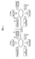
- the house code setting program in the PC 30 constructs a packet including 'a receiver adapter serial number' defining a receiver address, 'a PC network address' defining a transmitter address, and 'the house code' assigned from the managing site. (S46).
- the house code setting program transfers the packet to the adapter 20 (S47).
- reception of 'ACK' from the adapter 20 is determined (S48), and a determination that the house code setting is finished is made and the process is terminated if the 'ACK' is received, or the transfer of the packet is repeated if no 'ACK' is received.
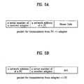
- the adapter 20 upon reception of the packet as shown in FIG. 5A, the adapter 20 responds with a packet constructed to include 'a PC network address' defining a receiver address, 'a receiver adapter serial number' defining a transmitter address, and the 'ACK' as shown in FIG. 5B.
- Each of the adapters 20 determines if a packet is received through a power line (S61). If the packet is received as a result of the determination (S61), each of the adapters 20 compares the house code in the packet to the house code set in the setting of the house code (S62).
- conformity of the house codes is determined (S63) as a result of the comparison (S62), and the packet is transferred to a connected appliance 20 if the house codes are in conformity (S64).
- the method for identifying multiple home networks having a common communication line can identify a home network in multiple home networks having a common communication line effectively by a simple setting and an algorithm addition without additional hardware, whereby permitting to make an efficient and reliable communication.
Landscapes
- Engineering & Computer Science (AREA)
- Automation & Control Theory (AREA)
- Computer Networks & Wireless Communication (AREA)
- Signal Processing (AREA)
- Computing Systems (AREA)
- Small-Scale Networks (AREA)
- Selective Calling Equipment (AREA)
- Data Exchanges In Wide-Area Networks (AREA)
- Cable Transmission Systems, Equalization Of Radio And Reduction Of Echo (AREA)
Description
- The present invention relates to a home network system, and more particularly, to a method for identifying multiple home networks sharing a communication line.
- WO 01/52515 discloses a communication and control system and methods according to the preamble of
independent claim 1. A plurality of networks used in the system may be coupled to a same power distribution trunk that is used as a communication line. Thus, it is possible for signals from one network to propagate to another network coupled to the same power distribution trunk. Each network comprises a plurality of interconnected devices that may be controlled by a controller. A house code is assigned to each device within one network, such that devices within one network can only communicate with a controller within the same network and not with controllers located in other networks coupled to the same power distribution trunk. - US 5 579 221 discloses a home automation system having a user controlled definition function being operated in response to input of an inherent call code. The system includes power line controller modules for switching power to appliances connected thereto in response to receipt of a control code. Each of the power line controller modules has an associated house code and unit code. The house code refers to an inherent household number and the unit code refers to a power line controller module unit number. A user manually sets these codes by a dual-in-line-switch DIP installed on the interior of power line controller modules.
- Home automation is discussed in the essay "PREISWERTE HAUS-BUSKOMMUNIKATION REUCKT NAEHER - DIE EUROPAEISCHEN POWERLINE-AKTIVITAETEN" by Bruno Jean-Bart, et. al. published in Elektronik 17/1998 on pages 74-77). The proposed method is based on the European home systems EHS. To allow communication within the system, a unique address has to be allocated to each device in the system. In this respect two approaches are proposed. According to a first approach called "Distributed address assignment", the device chooses an arbitrary address itself, and sends a message to this address. If no answer is received in response to this message, it is assumed that the address is not yet used in the system and the address is then assigned to the device. According to a second approach, individual addresses are retrieved from a separate node of the system that monitors the addresses used in the system.
- Currently, the home automation almost comes to a stage to put into practical use, in which home appliances are controlled automatically in a home or far from the home. Though an initial home automation is at a level the appliances are controlled separately by using a telephone line or an infrared ray, without interconnection between the appliances, currently a method is used, in which a network of the appliances are constructed by employing communication means, and a controller for controlling the network is provided, for integrated management of the network.
- The home network may be constructed by using an exclusive communication line for each home, or multiple home networks may be constructed by using a power line or a common communication line like a radio communication.
- In a case the home networks sharing the communication line are to be constructed, a technology for exact identification of a home network for each home is absolutely required for making reliable and effective communication within entire network.
- Presently, related art home networks sharing the communication line are under development, up to a stage to construct a conceptual system merely, but without practical application to each home, with the homes identified effectively.
- An object of the present invention designed for solving the foregoing problem lies on providing a method for identifying multiple home networks, in which each home network can be identified exactly, for making an effective communication.
- The above object is solved in a method comprising the features of the preamble of
independent claim 1 by the features of the characterizing part ofclaim 1. Preferred embodiments are defined in the dependent claims. - There is provided a method for identifying multiple home networks including the steps of setting a house code to each of adapters to the home appliances for identifying home networks, receiving a packet including the house code on the communication line at the adapters, and comparing a preset house code to the house code included in the packet, and one of the adapters understanding that the packet is directed to the one of the adapters if the two house codes are in conformity as a result of the comparison, and transferring the packet to one of the home appliances connected thereto.
- The accompanying drawings, which are included to provide a further understanding of the invention, illustrate embodiments of the invention and together with the description serve to explain the principles of the invention:
- In the drawings:
- FIG. 1 illustrates a layout of home networks sharing a communication line in accordance with a preferred embodiment of the present invention;
- FIG. 2 illustrates a block diagram of a detail system of the appliances and the power line communication adapters in FIG. 1;
- FIGS. 3A - 3C illustrate structures of communication packets transmitted in FIG. 1;
- FIG. 4 illustrates a flow chart showing the steps of a method for setting a code for identifying multiple home networks of the present invention;
- FIGS. 5A - 5C illustrate structures of communication packets transmitted in FIG. 4; and
- FIG. 6 illustrates a flow chart showing the steps of a method for identifying multiple home networks in accordance with a preferred embodiment of the present invention.
- Reference will now be made in detail to the preferred embodiments of the present invention, examples of which are illustrated in the accompanying drawings. In explaining the embodiments, the same names and reference symbols will be given to the same parts, and iterative description of the parts will be omitted.
- FIG. 1 illustrates a layout of home networks sharing a communication line in accordance with a preferred embodiment of the present invention, FIG. 2 illustrates a block diagram of a detail system of the appliances and the power line communication adapters in FIG. 1, FIGS. 3A - 3C illustrate structures of communication packets transmitted in FIG. 1, FIG. 4 illustrates a flow chart showing the steps of a method for setting a code for identifying multiple home networks of the present invention, FIGS. 5A - 5C illustrate structures of communication packets transmitted in FIG. 4, and FIG. 6 illustrates a flow chart showing the steps of a method for identifying multiple home networks in accordance with a preferred embodiment of the present invention.
- There are home network systems sharing a communication line of a power line of the present invention illustrated in FIG. 1.
- That is, a home 'A' and a home 'B' have home networks constructed respectively to share a communication line of a power line, with
home appliances 10 in each of the homes connected to the power line through a powerline communication adapters 20. APC 30 in each home serves as a controller for controlling the network. - A detailed system of FIG. 1 is illustrated in FIG. 2.
- That is, each
appliance 10 includes anon-volatile memory 11, amicrocomputer 12 for operation of the appliance and communication control, aserial communication port 14 for transmission/reception of data, and each of theadapters 20 includes anon-volatile memory 21, aserial communication port 22 for communication with theserial communication port 14 of theappliance 10, acommunication circuit 23, acommunication control microcomputer 24, and a powerline communication module 25 for enabling data communication through the power line. Theserial communication port 14 of each of theappliances 10 and theserial communication port 22 of theadapter 20 are connected, and the powerline communication module 25 of each of theadapters 20 is connected to the power line. - Structures of transmission packets of the appliances of the foregoing home networks are illustrated in FIGS. 3A - 3C. Referring to FIG. 3A, a transmission packet from the
appliance 10 to theadapter 20 includes an 'STX (starting code)', 'a receiver address', 'message to be transmitted', a 'CRC' (an error check code), and 'ETX (termination code)'. Referring to FIG. 3B, a transmission packet from theadapter 20 to the power line includes a 'house code', an 'STX', a 'receiver address', a 'transmitter address', a 'message to be transmitted', a 'CRC', and an 'ETX'. Referring to FIG. 3C, a transmission packet from theadapter 20 to theappliance 10 includes an 'STX', a 'receiver address', a 'transmitter address', a 'message to be transmitted', a 'CRC', and an 'ETX'. That is, the 'house code' is added only when a transmission is made through the power line. - At first, it is required that a method for identifying multiple home networks of the present invention is started from setting a house code to each of
adapters 20 for identifying respective homes. Accordingly, the house code setting will be explained in detail, with reference to FIG. 4. - A user or a service man from a manufacturer connects the
adapter 20 to an appliance 10 (S41). - Then, a program for setting a house code is put into operation in a PC 30 (S42). The program may be downloaded through Internet, or provided in a form of a CD or a diskette.
- A serial number of the user fitted adapter 200 is provided to the operative program for setting a house code (S43).
- Then, when the serial number is provided, the program for setting a house code makes an automatic access to a house code managing site (S44).
- Then, the accessed house code managing site assigns its own house code not in use at the present time, and transfers to the PC 30 (S45).
- Then, referring to FIG. 5A, the house code setting program in the
PC 30 constructs a packet including 'a receiver adapter serial number' defining a receiver address, 'a PC network address' defining a transmitter address, and 'the house code' assigned from the managing site. (S46). - Then, the house code setting program transfers the packet to the adapter 20 (S47).
- Then, reception of 'ACK' from the
adapter 20 is determined (S48), and a determination that the house code setting is finished is made and the process is terminated if the 'ACK' is received, or the transfer of the packet is repeated if no 'ACK' is received. - In this instance, upon reception of the packet as shown in FIG. 5A, the
adapter 20 responds with a packet constructed to include 'a PC network address' defining a receiver address, 'a receiver adapter serial number' defining a transmitter address, and the 'ACK' as shown in FIG. 5B. - In the meantime, a method for identifying respective home networks in transmission of the packet after finishing the house code setting as shown in FIG. 4 will be explained, with reference to FIG. 6.
- Each of the
adapters 20 determines if a packet is received through a power line (S61). If the packet is received as a result of the determination (S61), each of theadapters 20 compares the house code in the packet to the house code set in the setting of the house code (S62). - Then, conformity of the house codes is determined (S63) as a result of the comparison (S62), and the packet is transferred to a
connected appliance 20 if the house codes are in conformity (S64). - Opposite to this, if the house codes are not in conformity as the result of the determination (S63), the packet is disregarded (S65).
- Eventually, if a packet is transmitted through a common communication line, a power line, only a relevant appliance receives the packet, decodes to carry out a required operation order, without giving influence to other appliances.
- It will be apparent to those skilled in the art that various modifications and variations can be made in the method for identifying multiple home networks of the present invention without departing from the scope of the invention. Thus, it is intended that the present invention cover the modifications and variations of this invention provided they come within the scope of the appended claims and their equivalents.
- The method for identifying multiple home networks having a common communication line can identify a home network in multiple home networks having a common communication line effectively by a simple setting and an algorithm addition without additional hardware, whereby permitting to make an efficient and reliable communication.
Claims (3)
- A method for identifying multiple home networks each having a plurality of home appliances connected to respective adapters and a network controller, wherein an address is assigned to each home appliance, and at least two home networks share one communication line, the method comprising the steps of:setting a house code to each of the adapters connected to the home appliances for identifying home networks; andreceiving a packet including the house code on the communication line at the adapters;comparing a house code set to each of the adapters to the house code included in the packet; andone of the adapters understanding that the packet is directed to the one of the adapters if the two house codes are in conformity as a result of the comparison, and transferring the packet to one of the home appliances connected thereto,characterized in that the step of setting a house code includes the steps of:putting a house code setting program into operation in the network controller,providing a serial number of the adapter and making access to a house code managing site on the Internet in the program,receiving an own house code assigned from the house code managing site and transferring said house code to the relevant adapter, andthe adapter storing the house code to a relevant memory region.
- A method as claimed in claim 1, wherein the step of providing a serial number of the adapter and making access to a house code managing site on the Internet in the program includes the step of making an automatic access to the house code managing site once the serial number for the adapter is provided.
- A method as claimed in claim 1, further comprising the step of the adapters disregarding the received packet if the two house codes are not in conformity as the result of comparison.
Applications Claiming Priority (3)
| Application Number | Priority Date | Filing Date | Title |
|---|---|---|---|
| KR2002017807 | 2002-04-01 | ||
| KR10-2002-0017807A KR100425129B1 (en) | 2002-04-01 | 2002-04-01 | method for dividing multi home network system using common communication line |
| PCT/KR2002/000654 WO2003084143A1 (en) | 2002-04-01 | 2002-04-10 | Method for separating multiple home networks |
Publications (3)
| Publication Number | Publication Date |
|---|---|
| EP1523828A1 EP1523828A1 (en) | 2005-04-20 |
| EP1523828A4 EP1523828A4 (en) | 2005-09-14 |
| EP1523828B1 true EP1523828B1 (en) | 2007-01-03 |
Family
ID=28673047
Family Applications (1)
| Application Number | Title | Priority Date | Filing Date |
|---|---|---|---|
| EP02717207A Expired - Lifetime EP1523828B1 (en) | 2002-04-01 | 2002-04-10 | Method for separating multiple home networks |
Country Status (8)
| Country | Link |
|---|---|
| US (1) | US20050256944A1 (en) |
| EP (1) | EP1523828B1 (en) |
| KR (1) | KR100425129B1 (en) |
| CN (1) | CN1623298A (en) |
| AU (1) | AU2002248068A1 (en) |
| DE (1) | DE60217413T2 (en) |
| GB (1) | GB2402585B (en) |
| WO (1) | WO2003084143A1 (en) |
Families Citing this family (7)
| Publication number | Priority date | Publication date | Assignee | Title |
|---|---|---|---|---|
| KR100504610B1 (en) * | 2002-12-06 | 2005-08-01 | 엘지전자 주식회사 | Method for Setting Home Code of Home Network System |
| WO2005094190A2 (en) * | 2004-03-31 | 2005-10-13 | Lg Electronics, Inc. | Data receiving method and transferring method for data link layer |
| US7852842B2 (en) * | 2004-03-31 | 2010-12-14 | Lg Electronics Inc. | Data processing method for network layer |
| JP5094004B2 (en) * | 2005-10-20 | 2012-12-12 | パナソニック株式会社 | Data relay apparatus and data relay method |
| US7680906B2 (en) * | 2006-02-22 | 2010-03-16 | Microsoft Corporation | Configuring devices using context histories |
| CN104796853B (en) * | 2015-05-19 | 2018-07-06 | 北京子清智创科技有限公司 | A kind of communication system and method |
| US10186254B2 (en) | 2015-06-07 | 2019-01-22 | Apple Inc. | Context-based endpoint detection |
Family Cites Families (6)
| Publication number | Priority date | Publication date | Assignee | Title |
|---|---|---|---|---|
| GB8307149D0 (en) * | 1983-03-15 | 1983-04-20 | Emi Ltd | Data distribution network |
| KR0128169B1 (en) * | 1993-12-31 | 1998-04-15 | 김광호 | Home automation |
| US5949779A (en) * | 1997-05-08 | 1999-09-07 | Ericsson, Inc. | Multiprotocol adaptor for communication between CEBus devices and remote controllers over an ATM-based broadband access network |
| US6058355A (en) * | 1997-06-30 | 2000-05-02 | Ericsson Inc. | Automatic power outage notification via CEBus interface |
| JP3980131B2 (en) * | 1997-09-25 | 2007-09-26 | 松下電器産業株式会社 | Control device, initially settable communication system, and control method for initially settable communication system |
| US20020011923A1 (en) * | 2000-01-13 | 2002-01-31 | Thalia Products, Inc. | Appliance Communication And Control System And Appliance For Use In Same |
-
2002
- 2002-04-01 KR KR10-2002-0017807A patent/KR100425129B1/en not_active IP Right Cessation
- 2002-04-10 US US10/506,431 patent/US20050256944A1/en not_active Abandoned
- 2002-04-10 GB GB0419617A patent/GB2402585B/en not_active Expired - Fee Related
- 2002-04-10 CN CNA028286391A patent/CN1623298A/en active Pending
- 2002-04-10 WO PCT/KR2002/000654 patent/WO2003084143A1/en active IP Right Grant
- 2002-04-10 DE DE60217413T patent/DE60217413T2/en not_active Expired - Lifetime
- 2002-04-10 EP EP02717207A patent/EP1523828B1/en not_active Expired - Lifetime
- 2002-04-10 AU AU2002248068A patent/AU2002248068A1/en not_active Abandoned
Also Published As
| Publication number | Publication date |
|---|---|
| EP1523828A4 (en) | 2005-09-14 |
| CN1623298A (en) | 2005-06-01 |
| WO2003084143A1 (en) | 2003-10-09 |
| GB2402585B (en) | 2006-03-01 |
| DE60217413D1 (en) | 2007-02-15 |
| GB0419617D0 (en) | 2004-10-06 |
| AU2002248068A1 (en) | 2003-10-13 |
| GB2402585A (en) | 2004-12-08 |
| KR20030079047A (en) | 2003-10-10 |
| EP1523828A1 (en) | 2005-04-20 |
| DE60217413T2 (en) | 2007-10-18 |
| US20050256944A1 (en) | 2005-11-17 |
| KR100425129B1 (en) | 2004-03-30 |
Similar Documents
| Publication | Publication Date | Title |
|---|---|---|
| EP1569419B1 (en) | Method of assigning addresses to a plurality of devices on a network and a network system therefor | |
| KR100424297B1 (en) | Home Appliance Controlling System and Operating Method for the Same | |
| KR100565487B1 (en) | Home appliance network system and its method for the same | |
| KR100437042B1 (en) | Home Appliance Network System and Controlling Method for the Same | |
| US8145767B2 (en) | Sensor device, server node, sensor network system, method of establishing communication path, control program, and storage medium | |
| JP3112761U (en) | Home appliance network system | |
| US7430591B2 (en) | Methods and arrangements for configuring functional networks | |
| KR20040032644A (en) | Home network system's operating method | |
| US7158485B2 (en) | Method for joining node into subnet of power line communication network, electronic appliance connected to subnet, and communication module used in electronic appliance | |
| EP1523828B1 (en) | Method for separating multiple home networks | |
| US20030043845A1 (en) | Home appliance data transfer system and method for controlling the same | |
| US20050265245A1 (en) | Method of transferring data in a local household network | |
| WO2003079610A1 (en) | Method for confirming connection state of a home appliance in home network system | |
| US6538575B1 (en) | Control system, control device and controlled device | |
| US7539779B2 (en) | Method for separating multiple home networks | |
| EP1570576B1 (en) | Method for setting home code of home network system | |
| EP1011225A1 (en) | Method of network management and method of selection of network manager | |
| KR100565524B1 (en) | Home network system and its method for the same | |
| KR100381171B1 (en) | Home Appliance Controlling System and Operating Method for the Same | |
| KR100412357B1 (en) | A Home Appliance Networking System and Methods | |
| KR100565499B1 (en) | Plug-in method of master appliances | |
| KR100495058B1 (en) | Home appliance network system using power line communication and its method for the same | |
| KR100424319B1 (en) | Home Appliance Network System Controlling Method | |
| AU2002248066B2 (en) | Method for separating multiple home networks | |
| AU2002248066A1 (en) | Method for separating multiple home networks |
Legal Events
| Date | Code | Title | Description |
|---|---|---|---|
| PUAI | Public reference made under article 153(3) epc to a published international application that has entered the european phase |
Free format text: ORIGINAL CODE: 0009012 |
|
| 17P | Request for examination filed |
Effective date: 20050204 |
|
| AK | Designated contracting states |
Kind code of ref document: A1 Designated state(s): AT BE CH CY DE DK ES FI FR GB GR IE IT LI LU MC NL PT SE TR |
|
| AX | Request for extension of the european patent |
Extension state: AL LT LV MK RO SI |
|
| A4 | Supplementary search report drawn up and despatched |
Effective date: 20050801 |
|
| GRAP | Despatch of communication of intention to grant a patent |
Free format text: ORIGINAL CODE: EPIDOSNIGR1 |
|
| RIN1 | Information on inventor provided before grant (corrected) |
Inventor name: CHOI, HWAN JONG Inventor name: LIM, JEONG HYUN Inventor name: LEE, KOON SEOK Inventor name: BAEK, SEUNG MYUN |
|
| GRAS | Grant fee paid |
Free format text: ORIGINAL CODE: EPIDOSNIGR3 |
|
| GRAA | (expected) grant |
Free format text: ORIGINAL CODE: 0009210 |
|
| AK | Designated contracting states |
Kind code of ref document: B1 Designated state(s): DE FR |
|
| RAP1 | Party data changed (applicant data changed or rights of an application transferred) |
Owner name: LG ELECTRONICS INC. |
|
| REF | Corresponds to: |
Ref document number: 60217413 Country of ref document: DE Date of ref document: 20070215 Kind code of ref document: P |
|
| ET | Fr: translation filed | ||
| PLBE | No opposition filed within time limit |
Free format text: ORIGINAL CODE: 0009261 |
|
| STAA | Information on the status of an ep patent application or granted ep patent |
Free format text: STATUS: NO OPPOSITION FILED WITHIN TIME LIMIT |
|
| 26N | No opposition filed |
Effective date: 20071005 |
|
| PGFP | Annual fee paid to national office [announced via postgrant information from national office to epo] |
Ref country code: FR Payment date: 20140312 Year of fee payment: 13 |
|
| PGFP | Annual fee paid to national office [announced via postgrant information from national office to epo] |
Ref country code: DE Payment date: 20140312 Year of fee payment: 13 |
|
| REG | Reference to a national code |
Ref country code: DE Ref legal event code: R119 Ref document number: 60217413 Country of ref document: DE |
|
| PG25 | Lapsed in a contracting state [announced via postgrant information from national office to epo] |
Ref country code: DE Free format text: LAPSE BECAUSE OF NON-PAYMENT OF DUE FEES Effective date: 20151103 |
|
| REG | Reference to a national code |
Ref country code: FR Ref legal event code: ST Effective date: 20151231 |
|
| PG25 | Lapsed in a contracting state [announced via postgrant information from national office to epo] |
Ref country code: FR Free format text: LAPSE BECAUSE OF NON-PAYMENT OF DUE FEES Effective date: 20150430 |