EP1515443A1 - Frequency stabilisation of a current controlled oscillator used as a low frequency clock generator in a portable radio device - Google Patents
Frequency stabilisation of a current controlled oscillator used as a low frequency clock generator in a portable radio device Download PDFInfo
- Publication number
- EP1515443A1 EP1515443A1 EP03292213A EP03292213A EP1515443A1 EP 1515443 A1 EP1515443 A1 EP 1515443A1 EP 03292213 A EP03292213 A EP 03292213A EP 03292213 A EP03292213 A EP 03292213A EP 1515443 A1 EP1515443 A1 EP 1515443A1
- Authority
- EP
- European Patent Office
- Prior art keywords
- frequency
- oscillator circuit
- current
- signal
- control
- Prior art date
- Legal status (The legal status is an assumption and is not a legal conclusion. Google has not performed a legal analysis and makes no representation as to the accuracy of the status listed.)
- Granted
Links
Images
Classifications
-
- H—ELECTRICITY
- H03—ELECTRONIC CIRCUITRY
- H03L—AUTOMATIC CONTROL, STARTING, SYNCHRONISATION, OR STABILISATION OF GENERATORS OF ELECTRONIC OSCILLATIONS OR PULSES
- H03L7/00—Automatic control of frequency or phase; Synchronisation
- H03L7/06—Automatic control of frequency or phase; Synchronisation using a reference signal applied to a frequency- or phase-locked loop
- H03L7/08—Details of the phase-locked loop
-
- H—ELECTRICITY
- H03—ELECTRONIC CIRCUITRY
- H03K—PULSE TECHNIQUE
- H03K3/00—Circuits for generating electric pulses; Monostable, bistable or multistable circuits
- H03K3/01—Details
- H03K3/011—Modifications of generator to compensate for variations in physical values, e.g. voltage, temperature
-
- H—ELECTRICITY
- H03—ELECTRONIC CIRCUITRY
- H03K—PULSE TECHNIQUE
- H03K3/00—Circuits for generating electric pulses; Monostable, bistable or multistable circuits
- H03K3/02—Generators characterised by the type of circuit or by the means used for producing pulses
- H03K3/023—Generators characterised by the type of circuit or by the means used for producing pulses by the use of differential amplifiers or comparators, with internal or external positive feedback
- H03K3/0231—Astable circuits
-
- H—ELECTRICITY
- H03—ELECTRONIC CIRCUITRY
- H03L—AUTOMATIC CONTROL, STARTING, SYNCHRONISATION, OR STABILISATION OF GENERATORS OF ELECTRONIC OSCILLATIONS OR PULSES
- H03L1/00—Stabilisation of generator output against variations of physical values, e.g. power supply
- H03L1/02—Stabilisation of generator output against variations of physical values, e.g. power supply against variations of temperature only
- H03L1/022—Stabilisation of generator output against variations of physical values, e.g. power supply against variations of temperature only by indirect stabilisation, i.e. by generating an electrical correction signal which is a function of the temperature
Definitions
- the invention relates to a device and a method for Frequency stabilization of a current-controlled oscillator circuit according to the independent claims and thereon based an apparatus and a method for generating a frequency stabilized clock and a clock such device containing semiconductor chip.
- Time windows in TDMA methods.
- the Timing used for example to operate a real-time clock In mobile, network-independent devices is also the Power consumption of the clock will be low, above all during stand-by operation is important.
- a high-frequency crystal oscillator delivers one Highly accurate timing for data transmission.
- a low frequency Oscillator delivers a clock with less Accuracy and lower power consumption.
- the low-frequency oscillator can, for example, as external Component constructed in the form of a second quartz oscillator become.
- this increases the number of used Components, which is detrimental to the component costs, the Requires space and the power consumption of the circuit.
- the object of the invention is an apparatus and a method for frequency stabilization of a current controlled oscillator circuit specify which with a simplified Circuit design can be realized.
- the inventive device and the invention Methods are used for the frequency stabilization of a current-controlled Oscillator circuit, i. an oscillator circuit, its frequency over the strength of the control current can be adjusted.
- the device instructs in a comparison means for comparing the Output frequency of the oscillator circuit with the frequency a reference signal and a control means for setting the Control current of the oscillator circuit.
- An essential Thought of the invention is now within the Control means a resistance means with adjustable total resistance provided.
- the resistance agent is a Voltage applied and by means of the adjustable total resistance the current controlled.
- the comparison agent gives depending on a comparison of the output frequency of the controlling oscillator circuit having the frequency of a reference signal a control signal to the adjustable resistance means within the tax money.
- a stabilized voltage is applied to the resistance means, which, for example, in a known manner from a Band gap is derived.
- This will be a stabilized Control current generates the frequency of the oscillator circuit stabilized.
- the device according to the invention becomes the frequency of a current controlled oscillator circuit stabilized in a simplified way.
- the resistance means is controlled digitally by the comparison means.
- the control can be done via a bitword of width N. This restricts the adjustable resistances of the resistor to 2 N discrete states.
- the resistance means can thus be constructed as a resistance means whose total resistance can only be changed in discrete stages.
- the resistance means may be constructed, for example, of switches and associated resistors, each controllable switch being associated with a bit of the bitword. The total resistance of the resistance means can thus be determined by setting the bits of the bitword connected to switches.
- a further advantageous embodiment of the invention includes N one-way switches, which are independently controlled can be.
- Each of the N one-way switches is located doing so in one of N parallel current paths, respectively a series circuit including the switch and at least contain a resistor. This can be the total resistance of the resistance means linearly in small steps be varied.
- the comparison means advantageously consists of a derivation means, a control means, an adjustment means and optionally a filter.
- the dissipation agent directs from the feedback signal of the oscillator circuit as well from the reference signal depending on an intermediate signal, wherein both intermediate signals have an identical target frequency.
- the control agent determines based on the frequency deviation the two intermediate signals, a control signal, the necessary Frequency change of the oscillator circuit describes.
- the adjusting means takes the control signal of the control means and sets this in a control signal for the resistance means around.
- the adjusting means and the resistor means interposed a filter, the Oscillations of the control signal during the described calibration process suppressed.
- the filter can continue to do so be used to determine the end of the calibration process, So to determine when the balance of the oscillator circuit with the reference signal sufficient quality has reached. This is for example based on a characteristic Sequence of control signals detected.
- the derivation means has two independent channels. Each channel points a frequency divider, the respective input signal (The feedback signal of the oscillator circuit, as well as the Reference signal) receives. Both input signals have in general different frequencies and are governed by the two frequency divider into two output and intermediate signals implemented with identical target frequency. advantageously, can do without one of the two frequency dividers if, the target frequency is identical to the frequency of that input signal, which is the lower frequency having.
- the excellent meter reading can be the maximum value of respective counter and the output signal is with the Overflow signal of the counter identical.
- control means has this in addition to the resistance means an additional Means for controlling the control current of the oscillator circuit on which of the frequency changes of the oscillator circuit, as a result of a temperature change of the frequency-determining Components, counteracts.
- the frequency-determining Components are mainly within the Oscillator circuit and its control.
- Temperature fluctuations of the oscillator frequency are essentially due to fluctuations in the control current.
- An advantageous embodiment of the so-called Temperature compensation means is therefore simplified and mainly holds the control current with temperature changes constant.
- the temperature compensation agent thus acts the temperature dependence of the resistance means opposite or compensates for this temperature dependence.
- the temperature compensation agent as so-called PTAT source (Proportional To Absolute Temperature) train.
- a PTAT source has individual characteristics, which change in proportion to the absolute temperature.
- the control current thus remains constant Temperature fluctuations and thus also largely the Frequency of the oscillator circuit.
- the resistance means has a as simple as possible or easily compensated temperature response. This can be achieved by using the resistance means from as few as possible of different ones Consists of types of components and this in as possible are simply interconnected (e.g., waiving cascades).
- the resistance means in a particularly preferred embodiment identical, parallel Rungs, where the rungs each a series connection comprising a switch and a resistor.
- a temperature compensation agent By using a temperature compensation agent is the frequency stability significantly improved. Especially advantageous is the continuous correction of the oscillator frequency, reducing the time between two calibration cycles can be increased. This reduces the Number of calibration cycles required in a given period of time, resulting in an overall reduced power consumption reflects.
- the inventive method for frequency stabilization of a current controlled oscillator circuit includes the Calibration of the current-controlled oscillator circuit with a reference signal. First, the two frequencies compared, i. it will be the deviation of the frequency of the Oscillator circuit determined by a desired frequency. Out This deviation is a control variable determined with their Help a resistance means is controlled, which controls the control of the oscillator circuit and thus its frequency adapts.
- the frequency a current controlled oscillator circuit to simplified Fashion set.
- the method becomes the temperature-induced changes of the characteristics the frequency-determining components of the oscillator circuit and its control via a customized Strength of the control current compensated.
- control current becomes constant with temperature changes which, above all, the temperature-related change the resistance of the resistance means is met.
- the calibration of the oscillator circuit with a reference signal is the calibration of the oscillator circuit with a reference signal only within delimited time periods carried out.
- the compensation of the temperature dependence the frequency-determining components of the oscillator circuit and its control is carried out continuously.
- the periods of time during which the calibration of the oscillator circuit is done with a reference signal is by an increased power consumption of the invention Device marked. If the calibration is only in demarcated Time intervals are carried out, the sinks in the Average recorded power.
- the time interval between two time periods, during which the calibration of the oscillator circuit with a reference signal is increased, whereby the average power consumption of the invention Device continues to drop.
- Method for frequency stabilization of a current-controlled Oscillator circuit includes the necessary for calibration Comparison of the two input frequencies following substeps.
- a first step of the two Input signals two independent output signals with identical Target frequency derived.
- the two signals each one period of each Intermediate signal represent, to a so-called Signal pair are summarized.
- the two signals of the Signal pairs generally have a certain temporal Offset, the so-called phase of the signal pair.
- the phase of a Signal pair is, for example, by counting the pulses a high-frequency signal.
- the input signal with the higher frequency can be used.
- the phase determination is repeated. From this, the phase difference of two signal pairs is determined. Based on the phase difference and between the two signal pairs elapsed time can change to the necessary frequency the oscillator circuit inferred become.
- the inventive method for frequency stabilization of a current-controlled oscillator circuit can, for example used in a method for generating a timing become. However, there are still other uses conceivable.
- the device according to the invention and the inventive Method becomes a simplified structure of frequency stabilization a current controlled oscillator circuit realized.
- the advantageous embodiments are marked by a reduced power consumption of the device for frequency stabilization, as well as an improved Frequency constancy of the oscillator circuit.
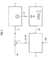
- Fig. 1 the current-controlled oscillator circuit 1 by a capacity and by the schematic representation the temporal voltage curve at the capacitance 14 in the form a triangle voltage indicated.
- Comparative 2 receives the output signal 201 of the oscillator circuit 1 and the reference signal 202. It generates a control signal from this 231/241, for example in the form of a bit word, for Control of the resistance 4.
- the control current 31 is controlled.
- the frequency adjusted Control current 31 can by means of the temperature compensation means 5, which is designed as a PTAT source, to Compensation of frequency fluctuations of the oscillator circuit additionally adjusted due to temperature fluctuations become. With the help of the control current 31/32 the frequency becomes the current controlled oscillator circuit 1 is controlled.
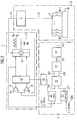
- the current controlled oscillator circuit 1 consists of a known multivibrator with comparators 11.
- the control current 32 is used for controlled charging and discharging of the capacitor 14 by means of the current converter 13.
- the voltage across the capacitance is monitored by means of two comparators 11.
- the comparators obtain their voltages V H and V L from a band gap. For example, when the lower voltage limit V L is reached, the corresponding comparator sends a signal to the control unit 12. This causes the current converter 13 to end the discharge process of the capacitor 14 and to start the charging process. The same happens when the upper voltage limit V H is reached .
- the output frequency 201 of the current-controlled oscillator circuit 1 is available via the lead 201.
- the output frequency of the oscillator circuit has a target value of 32,768 Hz.
- the output frequency 201 of the oscillator circuit 1 is fed to a counter 21.
- This counter 21 counts to 256, thereafter outputs an overflow signal on the output line 211, and starts counting again.
- On the output line 211 is therefore a signal with the target frequency of 128 Hz.
- the reference signal 202 is supplied to the counter 21 'with the frequency 26 MHz.
- On the output line 211 ' is after division of the signal by 203125 also a signal with the frequency of 128 Hz.
- the control means 22 measures the phase of a first and a second signal pair, for which purpose the pulses of the high-frequency reference signal between the signals of a given signal pair are counted. From the difference between the two phases, the necessary frequency change of the oscillator circuit is determined. A corresponding control signal is output via the supply lines 221 to the adjusting means 23. The adjusting means 23 changes the control signal 231 for the resistance means 4 accordingly.
- the control of the resistance means 4 via a multi-bit line 231/241 happens.
- the bitword on the multi-bit line 231/241 may be additionally filtered (filter 24) to avoid oscillations of the individual bit numbers during calibration. With the help of the bit word an adjustable resistance means 4 is controlled.
- the resistance means 4 consists of 50 parallel current paths in each of which a one-way switch and a single resistor are connected in series. The components in each current path are identical. Each switch of the variable resistance means 4 is controlled by one bit of the bit word 231/241. With the aid of the total resistance of the resistance means 4, the control current 31 is determined for the oscillator circuit.
- the control current 31 is additionally by the temperature compensation means 5, which consists of a PTAT source.
- the temperature compensation means 5 which consists of a PTAT source.
Abstract
Description
Die Erfindung betrifft eine Vorrichtung und ein Verfahren zur Frequenzstabilisierung eines stromgesteuerten Oszillatorschaltkreises nach den unabhängigen Patentansprüchen und darauf basierend eine Vorrichtung und ein Verfahren zur Erzeugung eines frequenzstabilisierten Zeittaktes und einen eine solche Vorrichtung enthaltenden Halbleiter-Chip.The invention relates to a device and a method for Frequency stabilization of a current-controlled oscillator circuit according to the independent claims and thereon based an apparatus and a method for generating a frequency stabilized clock and a clock such device containing semiconductor chip.
In elektronischen Geräten wird häufig ein Zeittakt benötigt, der verschiedensten Anforderungen genügen muss. In Geräten mit Funkschnittstelle beispielsweise unterscheiden sich die Anforderungen an die Genauigkeit während der Datenübertragung deutlich von der Anforderung im Stand-by-Betrieb. Während der Datenübertragung müssen Sende- und Empfangsgeräte ihre Zeittakte synchronisieren, z.B. zum korrekten Positionieren von Zeitfenstern bei TDMA-Verfahren. Im Stand-by-Betrieb wird der Zeittakt beispielsweise zum Betrieb einer Echtzeituhr verwendet. In mobilen, netzunabhängigen Geräten soll zudem die Leistungsaufnahme des Taktgebers gering sein, was vor Allem während des Stand-by-Betriebs wichtig ist.Electronic devices often require a time clock must meet the most diverse requirements. In devices with radio interface, for example, the differ Requirements for accuracy during data transmission clearly from the requirement in stand-by mode. During the Data transmission, transmitters and receivers have their clocks synchronize, e.g. for correct positioning of Time windows in TDMA methods. In stand-by mode, the Timing used for example to operate a real-time clock. In mobile, network-independent devices is also the Power consumption of the clock will be low, above all during stand-by operation is important.
Geräte mit Funkschnittstelle weisen daher typischerweise zwei Taktgeber auf. Ein hochfrequenter Quarzoszillator liefert einen hochgenauen Zeittakt für die Datenübertragung. Ein niederfrequenter Oszillator liefert einen Zeittakt mit geringerer Genauigkeit und geringerer Leistungsaufnahme.Devices with a radio interface therefore typically have two Clock on. A high-frequency crystal oscillator delivers one Highly accurate timing for data transmission. A low frequency Oscillator delivers a clock with less Accuracy and lower power consumption.
Der niederfrequente Oszillator kann beispielsweise als externes Bauelement in Form eines zweiten Quarzoszillators aufgebaut werden. Dies erhöht jedoch die Anzahl der verwendeten Bauelemente, was sich nachteilig auf die Bauteilkosten, den Platzbedarf und die Leistungsaufnahme der Schaltung auswirkt. The low-frequency oscillator can, for example, as external Component constructed in the form of a second quartz oscillator become. However, this increases the number of used Components, which is detrimental to the component costs, the Requires space and the power consumption of the circuit.
Aus der Patentschrift DE 100 29 421 C2 ist eine Vorrichtung bekannt, die den niederfrequenten Oszillator auf einem Halbleiter-Chip integriert. Nachteilig an einer derartigen Lösung ist die stark verminderte Frequenzkonstanz, wodurch häufige Kalibrierungen notwendig werden, was einen erhöhten Energieverbrauch bedingt. In einer Variante der in dieser Patentschrift beschriebenen Erfindung ist der niederfrequente integrierte Oszillator als durchstimmbarer, stromgesteuerter Oszillatorschaltkreis aufgebaut. In dieser Patentschrift wird jedoch keine konkrete Ausgestaltung der Variante beschrieben.From the patent DE 100 29 421 C2 is a device known the low-frequency oscillator on a semiconductor chip integrated. A disadvantage of such a solution is the greatly reduced frequency constancy, causing frequent Calibrations become necessary, resulting in increased energy consumption conditionally. In a variant of the in this patent described invention is the low-frequency integrated Oscillator as tunable, current controlled Built oscillator circuit. In this patent is However, no specific embodiment of the variant described.
Aufgabe der Erfindung ist es, eine Vorrichtung und ein Verfahren zur Frequenzstabilisierung eines stromgesteuerten Oszillatorschaltkreises anzugeben, welche mit einem vereinfachten Schaltungsaufbau realisiert werden können.The object of the invention is an apparatus and a method for frequency stabilization of a current controlled oscillator circuit specify which with a simplified Circuit design can be realized.
Diese Aufgabe wird durch die Merkmale der unabhängigen Patentansprüche gelöst. Vorteilhafte Weiterbildungen und Ausgestaltungen sind in den Unteransprüchen und in nebengeordneten Patentansprüchen angegeben. Somit sind ebenso eine Vorrichtung und ein Verfahren zur Erzeugung eines frequenzstabilisierten Zeittaktes und ein eine derartige Vorrichtung enthaltender Halbleiter-Chip angegeben.This object is achieved by the features of the independent claims solved. Advantageous developments and refinements are in the subclaims and in siblings Claims specified. Thus, also a device and a method for generating a frequency stabilized Timing and a device containing such a device Semiconductor chip specified.
Die erfindungsgemäße Vorrichtung und das erfindungsgemäße Verfahren dienen der Frequenzstabilisierung eines stromgesteuerten Oszillatorschaltkreises, d.h. eines Oszillatorschaltkreises, dessen Frequenz über die Stärke des Steuerstroms eingestellt werden kann. Die Vorrichtung weist in an sich bekannter Weise ein Vergleichsmittel zum Vergleichen der Ausgangsfrequenz des Oszillatorschaltkreises mit der Frequenz eines Referenzsignals und ein Steuermittel zum Einstellen des Steuerstroms des Oszillatorschaltkreises auf. Ein wesentlicher Gedanke der Erfindung besteht nun darin, innerhalb des Steuermittels ein Widerstandsmittel mit einstellbarem Gesamtwiderstand vorzusehen. An das Widerstandsmittel wird eine Spannung angelegt und mittels des einstellbaren Gesamtwiderstandes die Stromstärke gesteuert. Das Vergleichsmittel gibt in Abhängigkeit eines Vergleichs der Ausgangsfrequenz des zu steuernden Oszillatorschaltkreises mit der Frequenz eines Referenzsignals ein Steuersignal an das einstellbare Widerstandsmittel innerhalb des Steuermittels aus.The inventive device and the invention Methods are used for the frequency stabilization of a current-controlled Oscillator circuit, i. an oscillator circuit, its frequency over the strength of the control current can be adjusted. The device instructs in a comparison means for comparing the Output frequency of the oscillator circuit with the frequency a reference signal and a control means for setting the Control current of the oscillator circuit. An essential Thought of the invention is now within the Control means a resistance means with adjustable total resistance provided. The resistance agent is a Voltage applied and by means of the adjustable total resistance the current controlled. The comparison agent gives depending on a comparison of the output frequency of the controlling oscillator circuit having the frequency of a reference signal a control signal to the adjustable resistance means within the tax money.
An das Widerstandsmittel wird eine stabilisierte Spannung angelegt, welche zum Beispiel in bekannter Weise aus einer Bandlücke abgeleitet wird. Dadurch wird ein stabilisierter Steuerstrom erzeugt, der die Frequenz des Oszillatorschaltkreises stabilisiert. Durch die erfindungsgemäße Vorrichtung wird die Frequenz eines stromgesteuerten Oszillatorschaltkreises auf vereinfachte Art und Weise stabilisiert.A stabilized voltage is applied to the resistance means, which, for example, in a known manner from a Band gap is derived. This will be a stabilized Control current generates the frequency of the oscillator circuit stabilized. By the device according to the invention becomes the frequency of a current controlled oscillator circuit stabilized in a simplified way.
In einer vorteilhaften Ausgestaltung der Erfindung wird das Widerstandsmittel vom Vergleichsmittel digital angesteuert. Die Ansteuerung kann über ein Bitwort der Breite N geschehen. Dadurch werden die einstellbaren Widerstandswerte des Widerstandsmittels auf 2N diskrete Zustände beschränkt. Das Widerstandsmittel kann somit als Widerstandsmittel aufgebaut werden, dessen Gesamtwiderstand nur in diskreten Stufen verändert werden kann. Das Widerstandsmittel kann z.B. aus Schaltern und damit verbundenen Widerständen aufgebaut werden, wobei jeder steuerbare Schalter einem Bit des Bitwortes zugeordnet wird. Der Gesamtwiderstand des Widerstandsmittels kann somit durch Setzen der mit Schaltern verbundenen Bits des Bitwortes bestimmt werden.In an advantageous embodiment of the invention, the resistance means is controlled digitally by the comparison means. The control can be done via a bitword of width N. This restricts the adjustable resistances of the resistor to 2 N discrete states. The resistance means can thus be constructed as a resistance means whose total resistance can only be changed in discrete stages. The resistance means may be constructed, for example, of switches and associated resistors, each controllable switch being associated with a bit of the bitword. The total resistance of the resistance means can thus be determined by setting the bits of the bitword connected to switches.
Eine weitere vorteilhafte Ausgestaltung der Erfindung beinhaltet N Einwegeschalter, welche unabhängig voneinander gesteuert werden können. Jeder der N Einwegeschalter befindet sich dabei in einem von N parallelen Strompfaden, welche jeweils eine Serienschaltung beinhaltend den Schalter und mindestens einen Widerstand enthalten. Dadurch kann der Gesamtwiderstand des Widerstandsmittels in kleinen Schritten linear variiert werden.A further advantageous embodiment of the invention includes N one-way switches, which are independently controlled can be. Each of the N one-way switches is located doing so in one of N parallel current paths, respectively a series circuit including the switch and at least contain a resistor. This can be the total resistance of the resistance means linearly in small steps be varied.
Daneben sind noch eine Vielzahl anderer Schaltungen zum Einstellen diskreter Widerstandswerte denkbar.In addition, there are a variety of other circuits for setting discrete resistance values conceivable.
Das Vergleichsmittel besteht vorteilhafterweise aus einem Ableitungsmittel, einem Kontrollmittel, einem Einstellmittel sowie optional einem Filter. Das Ableitungsmittel leitet dabei aus dem Rückkoppelsignal des Oszillatorschaltkreises sowie aus dem Referenzsignal je ein Zwischensignal ab, wobei beide Zwischensignale eine identische Zielfrequenz besitzen. Das Kontrollmittel ermittelt anhand der Frequenzabweichung der beiden Zwischensignale ein Steuersignal, das die notwendige Frequenzänderung des Oszillatorschaltkreises beschreibt. Das Einstellmittel nimmt das Steuersignal des Kontrollmittels entgegen und setzt dieses in ein Steuersignal für das Widerstandsmittel um. Vorteilhafterweise ist dem Einstellmittel und dem Widerstandsmittel ein Filter zwischengeschaltet, das Oszillationen des Steuersignals während des beschriebenen Kalibriervorgangs unterdrückt. Das Filter kann weiterhin dazu eingesetzt werden, das Ende des Kalibriervorgangs zu bestimmen, also festzulegen, wann der Abgleich des Oszillatorschaltkreises mit dem Referenzsignal eine ausreichende Güte erreicht hat. Dies wird beispielsweise anhand einer charakteristischen Folge von Steuersignalen festgestellt.The comparison means advantageously consists of a derivation means, a control means, an adjustment means and optionally a filter. The dissipation agent directs from the feedback signal of the oscillator circuit as well from the reference signal depending on an intermediate signal, wherein both intermediate signals have an identical target frequency. The control agent determines based on the frequency deviation the two intermediate signals, a control signal, the necessary Frequency change of the oscillator circuit describes. The adjusting means takes the control signal of the control means and sets this in a control signal for the resistance means around. Advantageously, the adjusting means and the resistor means interposed a filter, the Oscillations of the control signal during the described calibration process suppressed. The filter can continue to do so be used to determine the end of the calibration process, So to determine when the balance of the oscillator circuit with the reference signal sufficient quality has reached. This is for example based on a characteristic Sequence of control signals detected.
In einer vorteilhaften Ausgestaltung des Ableitungsmittels weist dieses zwei unabhängige Kanäle auf. Jeder Kanal weist einen Frequenzteiler auf, der das jeweilige Eingangssignal (das Rückkoppelsignal des Oszillatorschaltkreises, sowie das Referenzsignal) entgegennimmt. Beide Eingangssignale besitzen im Allgemeinen verschiedene Frequenzen und werden durch die beiden Frequenzteiler in zwei Ausgangs- bzw. Zwischensignale mit identischer Zielfrequenz umgesetzt. Vorteilhafterweise kann dabei auf einen der beiden Frequenzteiler verzichtet werden wenn, die Zielfrequenz identisch ist mit der Frequenz desjenigen Eingangssignals, welches die geringere Frequenz aufweist. In einer weiteren vorteilhaften Ausgestaltung ist der bzw. sind die Frequenzteiler des Ableitungsmittels als Zähler ausgebildet, welche beim Erreichen eines ausgezeichneten Zählerstandes ein Ausgangssignal abgeben. Vorteilhafterweise kann der ausgezeichnete Zählerstand der Maximalwert des jeweiligen Zählers sein und das Ausgangssignal ist mit dem Überlaufsignal des Zählers identisch.In an advantageous embodiment of the derivation means This has two independent channels. Each channel points a frequency divider, the respective input signal (The feedback signal of the oscillator circuit, as well as the Reference signal) receives. Both input signals have in general different frequencies and are governed by the two frequency divider into two output and intermediate signals implemented with identical target frequency. advantageously, can do without one of the two frequency dividers if, the target frequency is identical to the frequency of that input signal, which is the lower frequency having. In a further advantageous embodiment the or are the frequency divider of the derivative means as Counter trained, which in achieving an excellent Meter reading output an output signal. advantageously, the excellent meter reading can be the maximum value of respective counter and the output signal is with the Overflow signal of the counter identical.
In einer weiteren vorteilhaften Ausgestaltung des Steuermittels weist dieses neben dem Widerstandsmittel ein zusätzliches Mittel zur Steuerung des Steuerstroms des Oszillatorschaltkreises auf, welches der Frequenzänderung des Oszillatorschaltkreises, in Folge einer Temperaturänderung der Frequenz-bestimmenden Bauteile, entgegenwirkt. Die Frequenz-bestimmenden Bauteile liegen dabei vornehmlich innerhalb des Oszillatorschaltkreises und seiner Ansteuerung.In a further advantageous embodiment of the control means has this in addition to the resistance means an additional Means for controlling the control current of the oscillator circuit on which of the frequency changes of the oscillator circuit, as a result of a temperature change of the frequency-determining Components, counteracts. The frequency-determining Components are mainly within the Oscillator circuit and its control.
Temperaturbedingte Schwankungen der Oszillatorfrequenz sind im Wesentlichen auf Schwankungen der Steuerstromstärke zurückzuführen. Eine vorteilhafte Ausgestaltung des sogenannten Temperaturausgleichsmittels ist daher vereinfacht aufgebaut und hält vornehmlich die Steuerstromstärke bei Temperaturänderungen konstant. Das Temperaturausgleichsmittel wirkt somit der Temperaturabhängigkeit des Widerstandsmittels entgegen bzw. gleicht diese Temperaturabhängigkeit aus.Temperature fluctuations of the oscillator frequency are essentially due to fluctuations in the control current. An advantageous embodiment of the so-called Temperature compensation means is therefore simplified and mainly holds the control current with temperature changes constant. The temperature compensation agent thus acts the temperature dependence of the resistance means opposite or compensates for this temperature dependence.
Es ist weiterhin vorteilhaft, das Temperaturausgleichsmittel als sogenannte PTAT-Quelle (Proportional To Absolute Temperature) auszubilden. Eine PTAT-Quelle besitzt einzelne Charakteristika, die sich proportional zur absoluten Temperatur ändern. In dieser vorteilhaften Ausgestaltung steigt dadurch der Anteil des Steuerstromes, der durch das Temperaturausgleichsmittel gesteuert wird, mit steigender Temperatur an, während der Anteil des Steuerstroms, der durch das Widerstandsmittel gesteuert wird, mit zunehmender Temperatur sinkt. In Summe bleibt somit der Steuerstrom konstant gegenüber Temperaturschwankungen und damit auch weitestgehend die Frequenz des Oszillatorschaltkreises.It is also advantageous, the temperature compensation agent as so-called PTAT source (Proportional To Absolute Temperature) train. A PTAT source has individual characteristics, which change in proportion to the absolute temperature. In this advantageous embodiment increases thereby the proportion of the control current generated by the temperature compensation agent controlled, with increasing temperature, while the proportion of the control current passing through the resistance means is controlled with increasing temperature sinks. In sum, the control current thus remains constant Temperature fluctuations and thus also largely the Frequency of the oscillator circuit.
Vorteilhafterweise besitzt dabei das Widerstandsmittel einen möglichst einfachen bzw. leicht zu kompensierenden Temperaturgang. Dies kann dadurch erreicht werden, dass das Widerstandsmittel aus einer möglichst geringen Anzahl von verschiedenen Bauteilgattungen besteht und diese in möglichst einfacher Weise verschaltet sind (z.B. Verzicht auf Kaskaden). Wie oben besprochen, enthält das Widerstandsmittel in einer besonders bevorzugten Ausführungsform identische, parallele Strompfade, wobei die Strompfade jeweils eine Serienschaltung aus einem Schalter und einem Widerstand umfassen.Advantageously, the resistance means has a as simple as possible or easily compensated temperature response. This can be achieved by using the resistance means from as few as possible of different ones Consists of types of components and this in as possible are simply interconnected (e.g., waiving cascades). As discussed above, the resistance means in a particularly preferred embodiment identical, parallel Rungs, where the rungs each a series connection comprising a switch and a resistor.
Durch die Verwendung eines Temperaturausgleichsmittels wird die Frequenzkonstanz wesentlich verbessert. Besonders vorteilhaft ist dabei die kontinuierliche Korrektur der Oszillatorfrequenz, wodurch der Zeitraum zwischen zwei Kalibrierungszyklen erhöht werden kann. Dadurch reduziert sich die Anzahl der in einem bestimmten Zeitraum notwendigen Kalibrierungszyklen, was sich in einer insgesamt verringerten Leistungsaufnahme widerspiegelt.By using a temperature compensation agent is the frequency stability significantly improved. Especially advantageous is the continuous correction of the oscillator frequency, reducing the time between two calibration cycles can be increased. This reduces the Number of calibration cycles required in a given period of time, resulting in an overall reduced power consumption reflects.
Das erfindungsgemäße Verfahren zur Frequenzstabilisierung eines stromgesteuerten Oszillatorschaltkreises beinhaltet die Kalibrierung des stromgesteuerten Oszillatorschaltkreises mit einem Referenzsignal. Dazu werden zuerst die beiden Frequenzen verglichen, d.h. es wird die Abweichung der Frequenz des Oszillatorschaltkreises von einer Sollfrequenz bestimmt. Aus dieser Abweichung wird eine Steuergröße ermittelt, mit deren Hilfe ein Widerstandsmittel gesteuert wird, welches den Steuerstrom des Oszillatorschaltkreises und somit dessen Frequenz anpasst. Durch das erfindungsgemäße Verfahren wird die Frequenz eines stromgesteuerten Oszillatorschaltkreises auf vereinfachte Art und Weise eingestellt.The inventive method for frequency stabilization of a current controlled oscillator circuit includes the Calibration of the current-controlled oscillator circuit with a reference signal. First, the two frequencies compared, i. it will be the deviation of the frequency of the Oscillator circuit determined by a desired frequency. Out This deviation is a control variable determined with their Help a resistance means is controlled, which controls the control of the oscillator circuit and thus its frequency adapts. By the method according to the invention, the frequency a current controlled oscillator circuit to simplified Fashion set.
In einer vorteilhaften Ausgestaltung des erfindungsgemäßen Verfahrens werden die temperaturbedingten Änderungen der Charakteristika der Frequenz-bestimmenden Bauteile des Oszillatorschaltkreises und seiner Ansteuerung über eine angepasste Stärke des Steuerstromes kompensiert.In an advantageous embodiment of the invention The method becomes the temperature-induced changes of the characteristics the frequency-determining components of the oscillator circuit and its control via a customized Strength of the control current compensated.
In einer bevorzugten Ausgestaltung des erfindungsgemäßen Verfahrens wird der Steuerstrom bei Temperaturänderungen konstant gehalten, womit vor Allem der temperaturbedingten Änderung des Widerstandes des Widerstandsmittels begegnet wird.In a preferred embodiment of the method according to the invention the control current becomes constant with temperature changes which, above all, the temperature-related change the resistance of the resistance means is met.
In einer bevorzugten Ausgestaltung des erfindungsgemäßen Verfahrens wird die Kalibrierung des Oszillatorschaltkreises mit einem Referenzsignal nur innerhalb abgegrenzter Zeitabschnitte durchgeführt. Die Kompensation der Temperaturabhängigkeit der Frequenz-bestimmenden Bauteile des Oszillatorschaltkreises und seiner Ansteuerung wird kontinuierlich durchgeführt. Die Zeitabschnitte, während denen die Kalibrierung des Oszillatorschaltkreises mit einem Referenzsignal erfolgt, ist durch eine erhöhte Leistungsaufnahme der erfindungsgemäßen Vorrichtung gekennzeichnet. Wird die Kalibrierung nur in abgegrenzten Zeitabschnitten durchgeführt, so sinkt die im Durchschnitt aufgenommene Leistung. Durch die kontinuierliche Kompensation der Temperaturabhängigkeit der Frequenz-bestimmenden Bauteile des Oszillatorschaltkreises und seiner Ansteuerung kann der zeitliche Abstand zwischen zwei Zeitabschnitten, während welchen die Kalibrierung des Oszillatorschaltkreises mit einem Referenzsignal erfolgt, erhöht werden, wodurch die durchschnittliche Leistungsaufnahme der erfindungsgemäßen Vorrichtung weiter sinkt. In a preferred embodiment of the method according to the invention is the calibration of the oscillator circuit with a reference signal only within delimited time periods carried out. The compensation of the temperature dependence the frequency-determining components of the oscillator circuit and its control is carried out continuously. The periods of time during which the calibration of the oscillator circuit is done with a reference signal is by an increased power consumption of the invention Device marked. If the calibration is only in demarcated Time intervals are carried out, the sinks in the Average recorded power. Through the continuous Compensation of the temperature dependence of the frequency-determining Components of the oscillator circuit and its Activation, the time interval between two time periods, during which the calibration of the oscillator circuit with a reference signal is increased, whereby the average power consumption of the invention Device continues to drop.
In einer vorteilhaften Ausgestaltung des erfindungsgemäßen Verfahrens zur Frequenzstabilisierung eines stromgesteuerten Oszillatorschaltkreises beinhaltet der zur Kalibrierung notwendige Vergleich der beiden Eingangsfrequenzen folgende Unterschritte. In einem ersten Schritt werden von den beiden Eingangssignalen zwei unabhängige Ausgangssignale mit identischer Zielfrequenz abgeleitet. Zu einem bestimmten Zeitpunkt können die zwei Signale, die jeweils eine Periode des jeweiligen Zwischensignals repräsentieren, zu einem sogenannten Signalpaar zusammengefasst werden. Die beiden Signale des Signalpaares haben im Allgemeinen einen gewissen zeitlichen Versatz, die sogenannte Phase des Signalpaares. Die Phase eines Signalpaares wird beispielsweise durch Zählen der Pulse eines hochfrequenten Signals bestimmt. Das Eingangssignal mit der höheren Frequenz kann dazu genutzt werden. Für das darauffolgende Signalpaar wird die Phasenbestimmung wiederholt. Daraus wird die Phasendifferenz zweier Signalpaare bestimmt. Anhand der Phasendifferenz und der zwischen den beiden Signalpaaren verstrichenen Zeit kann auf die notwendige Frequenzänderung des Oszillatorschaltkreises rückgeschlossen werden.In an advantageous embodiment of the invention Method for frequency stabilization of a current-controlled Oscillator circuit includes the necessary for calibration Comparison of the two input frequencies following substeps. In a first step of the two Input signals two independent output signals with identical Target frequency derived. At a certain time The two signals, each one period of each Intermediate signal represent, to a so-called Signal pair are summarized. The two signals of the Signal pairs generally have a certain temporal Offset, the so-called phase of the signal pair. The phase of a Signal pair is, for example, by counting the pulses a high-frequency signal. The input signal with the higher frequency can be used. For the following Signal pair, the phase determination is repeated. From this, the phase difference of two signal pairs is determined. Based on the phase difference and between the two signal pairs elapsed time can change to the necessary frequency the oscillator circuit inferred become.
Das erfindungsgemäße Verfahren zur Frequenzstabilisierung eines stromgesteuerten Oszillatorschaltkreises kann beispielsweise in einem Verfahren zur Erzeugung eines Zeittaktes eingesetzt werden. Es sind jedoch noch weitere Verwendungen denkbar.The inventive method for frequency stabilization of a current-controlled oscillator circuit can, for example used in a method for generating a timing become. However, there are still other uses conceivable.
Die oben besprochenen vorteilhaften Ausgestaltungen der erfindungsgemäßen Vorrichtung und des erfindungsgemäßen Verfahrens sind nicht voneinander getrennt zu betrachten. Die Erfindung betrifft vielmehr jegliche Kombination und Unterkombination der oben besprochenen vorteilhaften Ausgestaltungen. The above-discussed advantageous embodiments of the invention Device and the method according to the invention are not to be considered separately. The invention rather concerns any combination and subcombination the above-discussed advantageous embodiments.
Durch die erfindungsgemäße Vorrichtung und das erfindungsgemäße Verfahren wird ein vereinfachter Aufbau einer Frequenzstabilisierung eines stromgesteuerten Oszillatorschaltkreises realisiert. Die vorteilhaften Ausgestaltungen sind gekennzeichnet durch eine verringerte Leistungsaufnahme der Vorrichtung zur Frequenzstabilisierung, sowie eine verbesserte Frequenzkonstanz des Oszillatorschaltkreises.By the device according to the invention and the inventive Method becomes a simplified structure of frequency stabilization a current controlled oscillator circuit realized. The advantageous embodiments are marked by a reduced power consumption of the device for frequency stabilization, as well as an improved Frequency constancy of the oscillator circuit.
Nachfolgend wird anhand der Figuren ein Ausführungsbeispiel beschrieben. Es zeigen:
- Fig. 1:
- einen schematischen Überblick der erfindungsgemäßen Vorrichtung;
- Fig. 2:
- ein detailliertes Ausführungsbeispiel.
- Fig. 1:
- a schematic overview of the device according to the invention;
- Fig. 2:
- a detailed embodiment.
In Fig. 1 ist der stromgesteuerte Oszillatorschaltkreis 1
durch eine Kapazität und durch die schematische Darstellung
des zeitlichen Spannungsverlaufs an der Kapazität 14 in Form
einer Dreieckspannung angedeutet. Das Vergleichsmittel 2 erhält
das Ausgangssignal 201 des Oszillatorschaltkreises 1 sowie
das Referenzsignal 202. Es generiert daraus ein Steuersignal
231/241, beispielsweise in Form eines Bitwortes, zur
Ansteuerung des Widerstandsmittels 4. Mit Hilfe des Widerstandsmittels
4 wird der Steuerstrom 31 gesteuert. Der frequenzangepasste
Steuerstrom 31 kann mit Hilfe des Temperaturausgleichsmittels
5, das als PTAT-Quelle ausgebildet ist, zur
Kompensation von Frequenzschwankungen des Oszillatorschaltkreises
bedingt durch Temperaturschwankungen zusätzlich angepasst
werden. Mit Hilfe des Steuerstroms 31/32 wird die Frequenz
des stromgesteuerten Oszillatorschaltkreises 1 gesteuert.In Fig. 1, the current-controlled
In Fig. 2 ist ein detailliertes Ausführungsbeispiel der erfindungsgemäßen
Vorrichtung gezeigt. Der stromgesteuerte Oszillatorschaltkreis
1 besteht aus einem bekannten Multivibrator
mit Komparatoren 11. Der Steuerstrom 32 dient zum kontrollierten
Laden und Entladen der Kapazität 14 mit Hilfe des
Stromumsetzers 13. Die Spannung an der Kapazität wird mit
Hilfe zweier Komparatoren 11 überwacht. Die Komparatoren beziehen
ihre Spannungen VH bzw. VL aus einer Bandlücke. Wird
beispielsweise die untere Spannungsgrenze VL erreicht, sendet
der entsprechende Komparator ein Signal an die Kontrolleinheit
12. Diese veranlasst den Stromumsetzer 13, den Entladevorgang
der Kapazität 14 zu beenden und den Aufladevorgang zu
beginnen. Entsprechendes geschieht beim Erreichen der oberen
Spannungsgrenze VH. Über die Zuleitung 201 ist somit die Ausgangsfrequenz
201 des stromgesteuerten Oszillatorschaltkreises
1 verfügbar. Im vorliegenden Ausführungsbeispiel weist
die Ausgangsfrequenz des Oszillatorschaltkreises einen Sollwert
von 32.768 Hz auf. Die Ausgangsfrequenz 201 des Oszillatorschaltkreises
1 wird einem Zähler 21 zugeleitet. Dieser
Zähler 21 zählt bis 256, gibt danach ein Überlaufsignal auf
der Ausgangsleitung 211 aus und beginnt den Zählvorgang erneut.
Auf der Ausgangsleitung 211 liegt daher ein Signal mit
der Zielfrequenz 128 Hz an. Entsprechend wird dem Zähler 21'
das Referenzsignal 202 mit der Frequenz 26 MHz zugeführt. Auf
der Ausgangsleitung 211' liegt nach Teilung des Signals durch
203125 ebenfalls ein Signal mit der Frequenz 128 Hz an. Das
Kontrollmittel 22 misst die Phase eines ersten und eines
zweiten Signalpaares, wobei dazu die Pulse des hochfrequenten
Referenzsignals zwischen den Signalen eines gegebenen Signalpaares
gezählt werden. Aus der Differenz der beiden Phasen
wird die notwendige Frequenzänderung des Oszillatorschaltkreises
ermittelt. Ein entsprechendes Steuersignal wird über
die Zuleitungen 221 an das Einstellmittel 23 ausgegeben. Das
Einstellmittel 23 ändert das Steuersignal 231 für das Widerstandsmittel
4 entsprechend ab. Im vorliegenden Ausführungsbeispiel
geschieht die Ansteuerung des Widerstandsmittels 4
über eine Mehr-Bit-Leitung 231/241. Optional kann das Bitwort
auf der Mehr-Bit-Leitung 231/241 zusätzlich gefiltert werden
(Filter 24), um Oszillationen der einzelnen Bitzahlen während
der Kalibrierung zu vermeiden. Mit Hilfe des Bitwortes wird
ein einstellbares Widerstandsmittel 4 gesteuert. In diesem
Ausführungsbeispiel besteht das Widerstandsmittel 4 aus 50
parallelen Strompfaden in denen jeweils ein Einwegeschalter
und ein Einzelwiderstand in Serie geschaltet sind. Die Bauteile
in jedem Strompfad sind dabei identisch. Jeder Schalter
des einstellbaren Widerstandsmittels 4 wird anhand eines Bits
des Bitwortes 231/241 gesteuert. Mit Hilfe des Gesamtwiderstandes
des Widerstandsmittel 4 wird der Steuerstrom 31 für
den Oszillatorschaltkreis bestimmt.2 shows a detailed embodiment of the device according to the invention. The current controlled
Der Steuerstrom 31 wird zusätzlich durch das Temperatur-Ausgleichsmittel 5 gesteuert, das aus einer PTAT-Quelle besteht. Durch die Verwendung einer nur minimalen Anzahl von Bauteilarten in dem Widerstandsmittel und den einfachen Aufbau der Beschaltung, kann der Temperaturgang des Widerstandsmittels gut kompensiert werden. Der Steuerstrom 32 ist daher weitgehend konstant bei Temperaturschwankungen.The control current 31 is additionally by the temperature compensation means 5, which consists of a PTAT source. By using only a minimal number of Types of components in the resistor and the simple structure the wiring, the temperature response of the resistance means be well compensated. The control current 32 is therefore largely constant with temperature fluctuations.
Claims (16)
das Steuermittel (3) ein Widerstandsmittel (4) mit einstellbarem Gesamtwiderstand aufweist, durch welches der Steuerstrom (32) zumindest teilweise bestimmt wird.A device for frequency stabilization of a current-controlled oscillator circuit (1), comprising
the control means (3) comprises a resistance means (4) with adjustable total resistance, by which the control current (32) is at least partially determined.
dadurch gekennzeichnet, dass
das Widerstandsmittel (4) durch ein Bitwort (241) ansteuerbar ist, und eine Anzahl mit Widerständen verbundener Schalter aufweist, wobei jeweils ein Schalter durch ein Bit des Bitworts (241) gesteuert wird.Device according to claim 1,
characterized in that
the resistance means (4) is controllable by a bit word (241) and has a number of switches connected to resistors, one switch in each case being controlled by one bit of the bit word (241).
dadurch gekennzeichnet, dass
das Widerstandmittel (4) eine Anzahl paralleler Strompfade aufweist, welche jeweils eine Serienschaltung, enthaltend einen Widerstand und einen Einwegeschalter, enthalten.Device according to claim 2,
characterized in that
the resistance means (4) comprises a number of parallel current paths each including a series circuit including a resistor and a one-way switch.
dadurch gekennzeichnet, dass
das Vergleichsmittel (2)
characterized in that
the comparison means (2)
dadurch gekennzeichnet, dass
das Ableitungsmittel zwei Frequenzteiler (21,21') aufweist, wobei die Frequenzteiler (21,21') beide Eingangssignale (201,202) auf zwei Ausgangssignale (211,211') mit identischer Zielfrequenz umsetzen.Device according to claim 4,
characterized in that
the derivation means comprises two frequency dividers (21, 21 '), the frequency dividers (21, 21') converting both input signals (201, 202 ') to two output signals (211, 211') having the same target frequency.
dadurch gekennzeichnet, dass
die Frequenzteiler (21,21') des Ableitungsmittels als Zähler ausgebildet sind, die bei Erreichen eines bestimmten Zählerstandes ein Ausgangssignal (211,211') ausgegeben.Device according to claim 5,
characterized in that
the frequency divider (21,21 ') of the derivative means are designed as counters, which outputs an output signal (211,211') upon reaching a certain counter reading.
dadurch gekennzeichnet, dass
das Steuermittel (3) ferner ein Temperaturausgleichsmittel (5) zur zusätzlichen Steuerung des Steuerstroms (32) des Oszillatorschaltkreises (1) aufweist, welches der Frequenzänderung des Oszillatorschaltkreises (1), durch die temperaturbedingten Änderungen der Charakteristika der für die Frequenz maßgeblichen Bauelemente, insbesondere der temperaturbedingten Änderung des Steuerstroms (32), entgegenwirkt und insbesondere durch eine PTAT-Quelle gebildet ist.Device according to one or more of the preceding claims,
characterized in that
the control means (3) further comprising a temperature compensation means (5) for additionally controlling the control current (32) of the oscillator circuit (1), which changes the frequency of the oscillator circuit (1), due to the temperature changes of the characteristics of the frequency components, in particular the temperature-induced change of the control current (32), counteracts and in particular is formed by a PTAT source.
dadurch gekennzeichnet, dass
der stromgesteuerte Oszillatorschaltkreis (1) und/oder die Vorrichtung zu dessen Frequenzstabilisierung auf einem Halbleiter-Chip integriert ist.Device according to claim 8,
characterized in that
the current-controlled oscillator circuit (1) and / or the device for its frequency stabilization is integrated on a semiconductor chip.
der eine Vorrichtung gemäß Anspruch 9 aufweist.Semiconductor chip,
comprising a device according to claim 9.
bei welchem der Steuerstrom (32) des Oszillatorschaltkreises (1) durch Kalibrierung des stromgesteuerten Oszillatorschaltkreises (1) mit einem Referenzsignal (202) gesteuert wird, wobei die Kalibrierung folgende Teilschritte aufweist:
in which the control current (32) of the oscillator circuit (1) is controlled by calibration of the current-controlled oscillator circuit (1) with a reference signal (202), the calibration comprising the following substeps:
dadurch gekennzeichnet, dass
der Steuerstrom (32) des Oszillatorschaltkreises (1) zusätzlich in einer Art und Weise gesteuert wird, welche die Temperaturabhängigkeit der Frequenz-bestimmenden Bauteile des Oszillatorschaltkreises (1) und der Steuerung kompensiert, insbesondere wird der Steuerstrom (32) bei Temperaturänderungen konstant gehalten. Method according to claim 11,
characterized in that
the control current (32) of the oscillator circuit (1) is additionally controlled in a manner which compensates for the temperature dependence of the frequency-determining components of the oscillator circuit (1) and the controller, in particular the control current (32) is kept constant with temperature changes.
dadurch gekennzeichnet, dass
die Kalibrierung nur innerhalb abgegrenzter Zeitabschnitte durchgeführt wird.Method according to claim 11 or 12,
characterized in that
the calibration is carried out only within delimited periods of time.
dadurch gekennzeichnet, dass
die Kompensation der Temperaturabhängigkeit der Frequenz-bestimmenden Bauteile des Oszillatorschaltkreises kontinuierlich durchgeführt wird.Method according to claim 12 or 13,
characterized in that
the compensation of the temperature dependence of the frequency-determining components of the oscillator circuit is carried out continuously.
dadurch gekennzeichnet, dass
das Vergleichen der Frequenzen des Oszillatorschaltkreises (1) und des Referenzsignals (202) gemäß Teilschritt a) folgende Schritte beinhaltet:
characterized in that
comparing the frequencies of the oscillator circuit (1) and the reference signal (202) according to sub-step a) comprises the following steps:
Priority Applications (2)
| Application Number | Priority Date | Filing Date | Title |
|---|---|---|---|
| DE50304150T DE50304150D1 (en) | 2003-09-09 | 2003-09-09 | Frequency stabilization of a current-controlled oscillator circuit used as a low-frequency clock in mobile devices |
| EP20030292213 EP1515443B1 (en) | 2003-09-09 | 2003-09-09 | Frequency stabilisation of a current controlled oscillator used as a low frequency clock generator in a portable radio device |
Applications Claiming Priority (1)
| Application Number | Priority Date | Filing Date | Title |
|---|---|---|---|
| EP20030292213 EP1515443B1 (en) | 2003-09-09 | 2003-09-09 | Frequency stabilisation of a current controlled oscillator used as a low frequency clock generator in a portable radio device |
Publications (2)
| Publication Number | Publication Date |
|---|---|
| EP1515443A1 true EP1515443A1 (en) | 2005-03-16 |
| EP1515443B1 EP1515443B1 (en) | 2006-07-05 |
Family
ID=34130372
Family Applications (1)
| Application Number | Title | Priority Date | Filing Date |
|---|---|---|---|
| EP20030292213 Expired - Fee Related EP1515443B1 (en) | 2003-09-09 | 2003-09-09 | Frequency stabilisation of a current controlled oscillator used as a low frequency clock generator in a portable radio device |
Country Status (2)
| Country | Link |
|---|---|
| EP (1) | EP1515443B1 (en) |
| DE (1) | DE50304150D1 (en) |
Citations (5)
| Publication number | Priority date | Publication date | Assignee | Title |
|---|---|---|---|---|
| US4450518A (en) * | 1980-07-04 | 1984-05-22 | Itt Industries, Inc. | Control system for adjusting a physical quantity |
| US5543754A (en) * | 1994-10-11 | 1996-08-06 | National Semiconductor Corporation | Capacitor and resistor controlled oscillator timing lock loop for precision time constants |
| US5859560A (en) * | 1993-02-11 | 1999-01-12 | Benchmarq Microelectroanics, Inc. | Temperature compensated bias generator |
| US6100766A (en) * | 1997-05-16 | 2000-08-08 | Fujitsu Limited | Correction circuit controlling sensitivities of an oscillator circuit and electronic device using the same |
| DE10029421A1 (en) * | 2000-06-15 | 2002-01-03 | Infineon Technologies Ag | Calibration device and method for clock generation on an integrated circuit |
-
2003
- 2003-09-09 EP EP20030292213 patent/EP1515443B1/en not_active Expired - Fee Related
- 2003-09-09 DE DE50304150T patent/DE50304150D1/en not_active Expired - Fee Related
Patent Citations (5)
| Publication number | Priority date | Publication date | Assignee | Title |
|---|---|---|---|---|
| US4450518A (en) * | 1980-07-04 | 1984-05-22 | Itt Industries, Inc. | Control system for adjusting a physical quantity |
| US5859560A (en) * | 1993-02-11 | 1999-01-12 | Benchmarq Microelectroanics, Inc. | Temperature compensated bias generator |
| US5543754A (en) * | 1994-10-11 | 1996-08-06 | National Semiconductor Corporation | Capacitor and resistor controlled oscillator timing lock loop for precision time constants |
| US6100766A (en) * | 1997-05-16 | 2000-08-08 | Fujitsu Limited | Correction circuit controlling sensitivities of an oscillator circuit and electronic device using the same |
| DE10029421A1 (en) * | 2000-06-15 | 2002-01-03 | Infineon Technologies Ag | Calibration device and method for clock generation on an integrated circuit |
Also Published As
| Publication number | Publication date |
|---|---|
| EP1515443B1 (en) | 2006-07-05 |
| DE50304150D1 (en) | 2006-08-17 |
Similar Documents
| Publication | Publication Date | Title |
|---|---|---|
| DE102007034186B4 (en) | Digitally controlled oscillator | |
| DE10156027B4 (en) | Adjustable filter circuit | |
| DE10321200B3 (en) | Apparatus and method for calibrating R / C filter circuits | |
| DE69434280T2 (en) | Clock generator and phase comparator for use in such a clock generator | |
| DE69828300T2 (en) | DIGITAL FREQUENCY SYNTHESIS THROUGH SEQUENTIAL APPROACHES OF FRACTION PARTS | |
| DE102009016290B4 (en) | Electronic device and method for DC-DC conversion with slope compensation | |
| DE3841512C2 (en) | ||
| DE102008005927B4 (en) | Flexible oscillator structure | |
| DE19882089B4 (en) | Amplifier for continuous narrow-band signal amplification with high amplification factor and amplification method | |
| DE2216123C3 (en) | Process and arrangement for analog-digital conversion with multiple integration | |
| DE102007001148A1 (en) | Phase locked loop for quick adjustment and related method | |
| DE3324711C2 (en) | Pulse generator | |
| DE3036785C2 (en) | Oscillator circuit | |
| DE10048590B4 (en) | Phase-locked loop | |
| WO1998045950A1 (en) | Afc-digital tuning through mutual digital synthesis | |
| DE2943510C2 (en) | Phase-controlled high frequency oscillator | |
| DE1959162B2 (en) | Frequency generator adjustable in stages according to a frequency grid | |
| EP0166749B1 (en) | Phase regulation circuit | |
| EP1573921B1 (en) | Digitally controllable oscillator | |
| EP0630129A2 (en) | Method for generating a synchronised clock signal with a circuit for an adjustable oscillator | |
| EP1515443B1 (en) | Frequency stabilisation of a current controlled oscillator used as a low frequency clock generator in a portable radio device | |
| EP1922772A1 (en) | Circuit and method for controlling a piezoelectric or electrostrictive actuator | |
| DE19725587C2 (en) | Frequency multiplier to control the pulse width | |
| DE2513948A1 (en) | DECADICALLY ADJUSTABLE FREQUENCY GENERATOR WITH A PHASE-LOCKED CONTROL LOOP | |
| EP2569864B1 (en) | Circuit for clocking an fpga |
Legal Events
| Date | Code | Title | Description |
|---|---|---|---|
| PUAI | Public reference made under article 153(3) epc to a published international application that has entered the european phase |
Free format text: ORIGINAL CODE: 0009012 |
|
| AK | Designated contracting states |
Kind code of ref document: A1 Designated state(s): AT BE BG CH CY CZ DE DK EE ES FI FR GB GR HU IE IT LI LU MC NL PT RO SE SI SK TR |
|
| AX | Request for extension of the european patent |
Extension state: AL LT LV MK |
|
| 17P | Request for examination filed |
Effective date: 20050331 |
|
| 17Q | First examination report despatched |
Effective date: 20050506 |
|
| GRAP | Despatch of communication of intention to grant a patent |
Free format text: ORIGINAL CODE: EPIDOSNIGR1 |
|
| AKX | Designation fees paid |
Designated state(s): DE FR GB |
|
| GRAS | Grant fee paid |
Free format text: ORIGINAL CODE: EPIDOSNIGR3 |
|
| GRAA | (expected) grant |
Free format text: ORIGINAL CODE: 0009210 |
|
| AK | Designated contracting states |
Kind code of ref document: B1 Designated state(s): DE FR GB |
|
| REG | Reference to a national code |
Ref country code: GB Ref legal event code: FG4D Free format text: NOT ENGLISH |
|
| REF | Corresponds to: |
Ref document number: 50304150 Country of ref document: DE Date of ref document: 20060817 Kind code of ref document: P |
|
| PGFP | Annual fee paid to national office [announced via postgrant information from national office to epo] |
Ref country code: FR Payment date: 20060922 Year of fee payment: 4 |
|
| GBT | Gb: translation of ep patent filed (gb section 77(6)(a)/1977) |
Effective date: 20061005 |
|
| PGFP | Annual fee paid to national office [announced via postgrant information from national office to epo] |
Ref country code: DE Payment date: 20061114 Year of fee payment: 4 |
|
| ET | Fr: translation filed | ||
| PLBE | No opposition filed within time limit |
Free format text: ORIGINAL CODE: 0009261 |
|
| STAA | Information on the status of an ep patent application or granted ep patent |
Free format text: STATUS: NO OPPOSITION FILED WITHIN TIME LIMIT |
|
| 26N | No opposition filed |
Effective date: 20070410 |
|
| GBPC | Gb: european patent ceased through non-payment of renewal fee |
Effective date: 20070909 |
|
| PG25 | Lapsed in a contracting state [announced via postgrant information from national office to epo] |
Ref country code: DE Free format text: LAPSE BECAUSE OF NON-PAYMENT OF DUE FEES Effective date: 20080401 |
|
| REG | Reference to a national code |
Ref country code: FR Ref legal event code: ST Effective date: 20080531 |
|
| PG25 | Lapsed in a contracting state [announced via postgrant information from national office to epo] |
Ref country code: FR Free format text: LAPSE BECAUSE OF NON-PAYMENT OF DUE FEES Effective date: 20071001 |
|
| PG25 | Lapsed in a contracting state [announced via postgrant information from national office to epo] |
Ref country code: GB Free format text: LAPSE BECAUSE OF NON-PAYMENT OF DUE FEES Effective date: 20070909 |