EP1515278A1 - Video compression using dithering - Google Patents
Video compression using dithering Download PDFInfo
- Publication number
- EP1515278A1 EP1515278A1 EP03425590A EP03425590A EP1515278A1 EP 1515278 A1 EP1515278 A1 EP 1515278A1 EP 03425590 A EP03425590 A EP 03425590A EP 03425590 A EP03425590 A EP 03425590A EP 1515278 A1 EP1515278 A1 EP 1515278A1
- Authority
- EP
- European Patent Office
- Prior art keywords
- pixels
- string
- given
- error
- value
- Prior art date
- Legal status (The legal status is an assumption and is not a legal conclusion. Google has not performed a legal analysis and makes no representation as to the accuracy of the status listed.)
- Granted
Links
Images


Classifications
-
- H—ELECTRICITY
- H04—ELECTRIC COMMUNICATION TECHNIQUE
- H04N—PICTORIAL COMMUNICATION, e.g. TELEVISION
- H04N19/00—Methods or arrangements for coding, decoding, compressing or decompressing digital video signals
- H04N19/90—Methods or arrangements for coding, decoding, compressing or decompressing digital video signals using coding techniques not provided for in groups H04N19/10-H04N19/85, e.g. fractals
Definitions
- the present invention relates to techniques for the treatment of image signals.
- the invention has been developed with particular attention paid to the possibility of applying it to compression of RGB images on 24 bits per pixel with a view to their subsequent storage in a frame buffer.
- the reference to this particular type of application must not, however, be understood as in any way limiting the scope of the invention, which is altogether general.
- a true-colour image is made up of 8 bits for each chromatic component, for a total of 24 bits per pixel.
- a typical effect of dithering may be encountered on television displays or in typographical prints.
- the images seem to comprise many colours or many different shades or nuances of colour, but when they are observed in greater detail, it is found not to be the case.
- a television image even though it may appear to have a continuous tone, uses only three colours set in various states of activation/deactivation.
- Typographical print for example newspaper print, uses only black ink; however, the images appear to be made up of grey tones.
- the principle of dithering is based upon the simulation of an intermediate tone by mixing, in appropriate amounts (for example as a result of different geometrical distributions), just two colours, for instance, black and white for simulation of an entire range of grey.
- the purpose of the invention is to provide an altogether satisfactory solution to meet this need.
- the invention also relates to a corresponding system, as well as to a corresponding computer product that can be loaded into the memory of a computer, such as a processor, and comprises portions of software code for implementing the method according to the invention when the computer product is run on a computer.
- the system represented in Figure 1 comprises a source of video signals 10 constituted, for example, by a television camera, a photographic camera, or a scanner that explores an "original" image, generating at its output signals 12.
- the signals 12 are typically constituted by digital colour video signals organized according to an RGB format.
- Video-image sources corresponding to the description provided herein for the source 10 are widely known to the art, this rendering altogether superfluous a more detailed description herein.
- the signals 12 are supplied to a computer such as, for example, a processor 14, which (operating according to the criteria described in greater detail in what follows) generates at its output video signals 16 corresponding to the signals 12 supplied to its input but subjected to an operation of compression with a view to their subsequent storage in a memory 18.
- a computer such as, for example, a processor 14, which (operating according to the criteria described in greater detail in what follows) generates at its output video signals 16 corresponding to the signals 12 supplied to its input but subjected to an operation of compression with a view to their subsequent storage in a memory 18.
- the processor 14 can be constituted either by a dedicated processor or else by a processor of a general-purpose type (for example, of the DSP type) configured - according to criteria in themselves known, i.e., by loading of a corresponding computer product - for implementing the processing operations described in greater detail in what follows.
- a processor of a general-purpose type for example, of the DSP type
- the reference number 20 indicates in the diagram of Figure 1 a reading device of any known type.
- the device is able to gain access to the memory 18 by reading the video signals stored therein and supplying them to a display unit 22 represented, for example, by a liquidcrystal display.
- a first technique is the "clamping" technique.
- the above technique is also suited for being implemented in a differentiated way on the various chromatic components, for example eliminating the three least-significant bits of the red (R) and blue (B) components and only two bits of the green (G) component, which is usually the one to which the human eye is most sensitive.
- the final result of the above operation is, in the first place, a constructed image generally darker than of the original one. Furthermore, the final result may be very poor in certain types of image, for example images such as the image Topsmap.rgb, with a continuous colour gradient.
- the quality that may be achieved is as a whole modest: for standard images, such as Topsmap.rgb already considered previously, there is a slight improvement with respect to the pure and simple clamping technique. For other images, such as Forrest.rgb and Image0.rgb, there is practically no difference between the clamping/truncation technique and the integer-rounding technique.
- the threshold can be a fixed one or else depend upon the position of the pixel both at a local level and at a global level in the image. Frequently, the use of a fixed threshold gives rise to modest results, whereas with the use of thresholds that vary according to the position much better results are obtained.
- the technique can be further improved by resorting to threshold arrays containing a regular distribution of fields of thresholds for each pixel position.
- a further known dithering technique is the one that goes by the name of Floyd-Steinberg method.
- the Floyd-Steinberg method is based upon a criterion of error diffusion (or dispersion): the rounding error associated to each pixel is propagated to the adjacent pixels with a view to it possible compensation.
- the error-dispersion technique operates in such a way that, for each point of the image, there is identified in the first place the closest available colour. Once the difference between the value of the image and the available colour has been calculated, the corresponding error values are distributed over the adjacent pixels that have not yet been treated. When these further pixels are to be treated, there are added thereto the distributed errors starting from the preceding ones, a clipping action being carried out in order to remain within the range of the admissible values; then the process proceeds in a similar manner on the rest of the image.
- the reference M indicates a set of pixels constituted by a 2x2 array, i.e., ones comprising four pixels.
- step 100 which follows the step of state of the procedure: operating on the 4 pixels A, B, C and D of the array ( Figure 3) there will hence be obtained four components/truncated strings At, Bt, Ct, Dt.
- a step designated by 106 there is calculated a set of values of global error ( ⁇ ) comprising all the possible combinations of addition of said first and second pixel error values on the pixels of the group.
- ⁇ a At - A is calculated with sign and may thus also be negative; otherwise, ⁇ would be always positive and the corresponding minimum would be always equal to ⁇ a.
- the solution described herein envisages minimizing the global error of the array, by taking the lowest value among those considered previously.
- the operation is performed of truncating all the pixels of the four least-significant bits.
- the minimum is represented by the value designated by 2, 2 4 is added only to one pixel in the array, and the other three are truncated.
- 2 4 is added only to two pixels in the array, and the other two are truncated.
- the minimum is represented by the value designated by 4
- 2 4 is added only to three pixels within the array, and the remaining one is truncated.
- 2 4 is added to all four pixels in the array, without making any truncation.
- a step 110 all the samples thus obtained are subjected to truncation of the four least-significant bits before being stored in the memory 18 in a step 112.
- pixels in the array are taken in a random way, for example in the following way:
- the simplest solution consists simply of reading the compressed signals from the memory 18 and decompressing them by adding 4 least-significant bits all equal to 0.
- a possible variant embodiment of the solution described herein envisages mixing the solution described previously with an error-diffusion technique.
- the minimum global error in the current array (for example a 2x2 array) is distributed over the subsequent global error in the array taken into consideration immediately after in the image.
- ⁇ n-1 is the minimum global error determined for the preceding array in the process of scanning of the image (of course, with reference to the same chromatic component).
- either a visual evaluation of the quality of the image or a calculation of the peak signal-to-noise ratio (PSNR) may be resorted to.
- PSNR peak signal-to-noise ratio
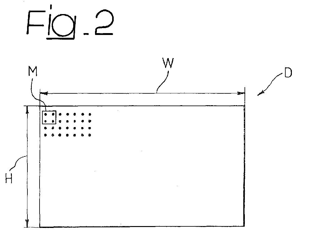
- the peak signal-to-noise ratio is defined with reference to a parameter of mean-square error (MSE) defined according to the relation: where M and N are, respectively, the height and the width of the image, I(x, y) is the original image, I' (x, y) is the image compressed and then decompressed which is to be compared with the original.
- MSE mean-square error
- the peak signal-to-noise ratio PSNR is defined - in the example considered herein - as
- PSNR Typical values of PSNR are usually comprised between 20 dB and 48 dB, preferably expressed with two decimal figures (for example 36.27 dB).
- a value of 48 dB identifies practically a situation in which the human eye is not able to appreciate visual artefacts.
- a better compression leads to a lower value of MSE which, in turn, leads to a higher PSNR.
Landscapes
- Engineering & Computer Science (AREA)
- Multimedia (AREA)
- Signal Processing (AREA)
- Image Processing (AREA)
- Facsimile Image Signal Circuits (AREA)
- Color Image Communication Systems (AREA)
Abstract
Description
- Figure 1 is a block diagram representing a system that is able to operate according to the invention;
- Figures 2 and 3 are two schematic representations of the mode of operation of the solution described herein; and
- Figure 4 is a flowchart further illustrating the mode of operation of the solution described herein.
- on the one hand, the truncated values At, Bt, Ct, Dt, thus obtaining first difference/error values; and
- on the other hand, the integrated values Ai, Bi, Ci, Di, thus obtaining second difference/error values.
Claims (31)
- A method for processing digital video signals (12), in which the pixels of the image have associated to them at least one respective string of bits (A, B, C, D), said method being characterized in that it comprises the steps of:ordering (100) said pixels in groups of adjacent pixels (A, B, C, D);performing, for the pixels comprised in each of said groups, the operations of:- i) truncating the respective string of bits, eliminating a given number (n) of least-significant bits, thus generating a respective truncated string (At, Bt, Ct, Dt);- ii) adding to said truncated string an integration factor constituted by a power of two of a given order, thus generating a respective integrated string (Ai, Bi, Ci, Di); and- iii) calculating first values of pixel error corresponding to the difference between said respective string and the respective truncated string (A-At, B-Bt, C-Ct, D-Dt) and second values of pixel error corresponding to the difference between said respective string and the respective integrated string (A-Ai, B-Bi, C-Ci, D-Di);calculating, for each of said groups of pixels, a set of values of global error (Δ) comprising all the possible combinations of addition of said first and second values of pixel error on the pixels of the group;locating the value of minimum error in said set of values of global error, identifying moreover, in the combination of addition that produces said value of minimum global error, a first number of pixels, whereby the contribution to said value of minimum global error is given by said first value of pixel error, and a second number of pixels, whereby the contribution to said value of minimum global error is given by the second value of pixel error; andusing, as compressed version of the video signals represented by the pixels in the group, a first number of said truncated strings (At, Bt, Ct, Dt) and a second number of said integrated strings (Ai, Bi, Ci, Di) that are equal to said first number of pixels and to said second number of pixels respectively, said integrated strings being subjected to truncation by the elimination of said given number of least-significant bits.
- The method according to Claim 1, characterized in that said first number of integrated strings (Ai, Bi, Ci, Di) is used for representing the pixels in said group whereby the least-significant bits of the respective string of bits (A, B, C, D) is greater than a given threshold.
- The method according to Claim 2, characterized in that said threshold is given by a power of two of order (2n-1) lower by one unit with respect to said given order (2n).
- The method according to any one of the preceding claims, characterized in that it comprises the operation of choosing, at least in part, in a random way, the pixels in said group in which, as compressed version, there is used the respective truncated string (At, Bt, Ct, Dt) and the respective integrated string (Ai, Bi, Ci, Di) subjected to truncation.
- The method according to any one of the preceding claims, applied to digital video signals in which the pixels of the image have associated to them a plurality of respective strings of bits (A, B, C, D), each of which is representative of a respective chromatic component (R, G, B) of the pixel, said method being characterized in that it comprises the operation of repeating the steps according to Claim 1 for each of the strings of bits of said plurality.
- The method according to Claim 5, characterized in that said given number of least-significant bits is chosen equal for all the chromatic components of said plurality.
- The method according to Claim 5, characterized in that said given number of least-significant bits is chosen different for the chromatic components of said plurality.
- The method according to any one of Claims 1 to 7, characterized in that said given order is chosen equal to said given number (n).
- The method for processing video signals, characterized in that it comprises the operation of repeating the sequence of steps according to any one of Claims 1 to 8, in sequence for successive groups of pixels of said image, according to a determined scanning order.
- The method according to Claim 9, characterized in that said scanning order is a lexicographic scanning order.
- The method according to Claim 9 or Claim 10, characterized in that it comprises the operation of adding to the possible combinations of addition comprised in said set of values of global error (Δ), calculated for a determined group of pixels in said ordered sequence, the value of minimum global error located for the preceding group of pixels in said scanning order.
- The method according to any one of the preceding claims, characterized in that said groups of pixels are constituted by arrays of pixels.
- The method according to Claim 12, characterized in that said groups of pixels are constituted by square matrices of pixels.
- The method according to any one of the preceding claims, characterized in that said groups of pixels comprise a number of pixels equal to four.
- The method according to any one of the preceding claims, characterized in that said digital video signals are signals in RGB format.
- A system for processing digital video signals (12), in which the pixels of the image have associated to them at least one respective string of bits (A, B, C, D), the system being characterized in that it comprises at least one processing device (14) configured for implementing the steps of:ordering (100) said pixels in groups of adjacent pixels (A, B, C, D);performing, for the pixels comprised in each of said groups, the operations of:- i) truncating the respective string of bits, eliminating a given number (n) of least-significant bits, thus generating a respective truncated string (At, Bt, Ct, Dt);- ii) adding to said truncated string an integration factor constituted by a power of two of a given order, thus generating a respective integrated string (Ai, Bi, Ci, Di); and- iii) calculating first values of pixel error corresponding to the difference between said respective string and the respective truncated string (A-At, B-Bt, C-Ct, D-Dt) and second values of pixel error corresponding to the difference between said respective string and the respective integrated string (A-Ai, B-Bi, C-Ci, D-Di);calculating, for each of said groups of pixels, a set of values of global error (Δ) comprising all the possible combinations of addition of said first and second values of pixel error on the pixels of the group;locating the value of minimum error in said set of values of global error, identifying moreover, in the combination of addition that produces said value of minimum global error, a first number of pixels, whereby the contribution to said value of minimum global error is given by said first value of pixel error, and a second number of pixels, whereby the contribution to said value of minimum global error is given by the second value of pixel error; andusing, as compressed version of the video signals represented by the pixels in the group, a first number of said truncated strings (At, Bt, Ct, Dt) and a second number of said integrated strings (Ai, Bi, Ci, Di) that are equal to said first number of pixels and to said second number of pixels respectively, said integrated strings being subjected to truncation by the elimination of said given number of least-significant bits.
- The system according to Claim 16, characterized in that said processing device (14) is configured for using said first number of integrated strings (Ai, Bi, Ci, Di) for representing the pixels in said group so that the least-significant bits of the respective string of bits (A, B, C, D) is greater than a given threshold.
- The system according to Claim 17, characterized in that said threshold is given by a power of two of order (2n-1) lower by one unit with respect to said given order (2n).
- The system according to any one of the preceding Claims 16 to 18, characterized in that said processing device (14) is configured for choosing, at least in part, in a random way, the pixels in said group, in which, as a compressed version, there are used the respective truncated string (At, Bt, Ct, Dt) and the respective integrated string (Ai, Bi, Ci, Di) subjected to truncation.
- The system according to any one of the preceding Claims 16 to 19, for the treatment of digital video signals, in which the pixels of the image have associated to them a plurality of respective strings of bits (A, B, C, D) each representative of a respective chromatic component (R, G, B) of the pixel, said system being characterized in that said processing device (14) is configured for repeating the steps according to Claim 16 for each of the strings of bits of said plurality.
- The system according to Claim 20, characterized in that said processing device (14) is configured for choosing said given number of least-significant bits equal for all the chromatic components of said plurality.
- The system according to Claim 20, characterized in that said processing device (14) is configured for choosing said given number of least-significant bits in a different way for the chromatic components of said plurality.
- The system according to any one of Claims 16 to 22, characterized in that said processing device (14) is configured for choosing said given order equal to said given number (n).
- The system according to any one of Claims 16 to 23, characterized in that said processing device (14) is configured for operating in sequence for subsequent groups of pixels of said image according to a given scanning order.
- The system according to Claim 24, characterized in that said scanning order is a lexicographic scanning order.
- The system according to Claim 24 or Claim 25, characterized in that said processing device (14) is configured for adding to the possible combinations of addition comprised in said set of values of global error (Δ) calculated for a given group of pixels in said ordered sequence, the value of minimum global error located for the preceding group of pixels in said scanning order.
- The system according to any one of the preceding Claims 16 to 26, characterized in that said groups of pixels are constituted by arrays of pixels.
- The system according to Claim 27, characterized in that said groups of pixels are constituted by square matrices of pixels.
- The system according to any one of the preceding Claims 16 to 28, characterized in that said groups of pixels comprise a number of pixels equal to four.
- The system according to any one of the preceding Claims 16 to 29, characterized in that said digital video signals are signals in RGB format.
- A computer product which can be loaded into the memory of a computer and comprises portions of software code for implementing the method according to any one of Claims 1 to 15 when the product is run on a computer.
Priority Applications (3)
| Application Number | Priority Date | Filing Date | Title |
|---|---|---|---|
| EP03425590A EP1515278B1 (en) | 2003-09-11 | 2003-09-11 | Video compression using dithering |
| DE60312162T DE60312162D1 (en) | 2003-09-11 | 2003-09-11 | Video compression using dithering |
| US10/938,426 US7529299B2 (en) | 2003-09-11 | 2004-09-10 | Method and system for processing image signals and computer program product therefor |
Applications Claiming Priority (1)
| Application Number | Priority Date | Filing Date | Title |
|---|---|---|---|
| EP03425590A EP1515278B1 (en) | 2003-09-11 | 2003-09-11 | Video compression using dithering |
Publications (2)
| Publication Number | Publication Date |
|---|---|
| EP1515278A1 true EP1515278A1 (en) | 2005-03-16 |
| EP1515278B1 EP1515278B1 (en) | 2007-02-28 |
Family
ID=34130432
Family Applications (1)
| Application Number | Title | Priority Date | Filing Date |
|---|---|---|---|
| EP03425590A Expired - Fee Related EP1515278B1 (en) | 2003-09-11 | 2003-09-11 | Video compression using dithering |
Country Status (3)
| Country | Link |
|---|---|
| US (1) | US7529299B2 (en) |
| EP (1) | EP1515278B1 (en) |
| DE (1) | DE60312162D1 (en) |
Families Citing this family (18)
| Publication number | Priority date | Publication date | Assignee | Title |
|---|---|---|---|---|
| US7471300B2 (en) * | 2005-01-18 | 2008-12-30 | Intel Corporation | Progressive data delivery to spatial light modulators |
| US7486834B2 (en) * | 2005-01-18 | 2009-02-03 | Lexmark International, Inc. | System and method for dynamically shifting error diffusion data |
| US9024966B2 (en) * | 2007-09-07 | 2015-05-05 | Qualcomm Incorporated | Video blending using time-averaged color keys |
| KR101394151B1 (en) * | 2007-10-04 | 2014-05-14 | 삼성전자주식회사 | Apparatus and method for encoding image using a psycho-visual characteristic |
| US8654838B2 (en) | 2009-08-31 | 2014-02-18 | Nxp B.V. | System and method for video and graphic compression using multiple different compression techniques and compression error feedback |
| GB2475878A (en) * | 2009-12-03 | 2011-06-08 | St Microelectronics | Obtaining dithered image data word by adding noise contribution |
| CN103175834B (en) * | 2013-01-28 | 2016-05-18 | 宁波江丰生物信息技术有限公司 | A kind of digital pathological section quality determining method and system |
| US9418396B2 (en) | 2015-01-15 | 2016-08-16 | Gopro, Inc. | Watermarking digital images to increase bit depth |
| US9877036B2 (en) | 2015-01-15 | 2018-01-23 | Gopro, Inc. | Inter frame watermark in a digital video |
| US9886961B2 (en) | 2015-01-15 | 2018-02-06 | Gopro, Inc. | Audio watermark in a digital video |
| US20170006219A1 (en) | 2015-06-30 | 2017-01-05 | Gopro, Inc. | Image stitching in a multi-camera array |
| US10051206B2 (en) | 2015-09-28 | 2018-08-14 | Gopro, Inc. | Automatic composition of video with dynamic background and composite frames selected based on frame and foreground object criteria |
| US10045120B2 (en) | 2016-06-20 | 2018-08-07 | Gopro, Inc. | Associating audio with three-dimensional objects in videos |
| US9749738B1 (en) | 2016-06-20 | 2017-08-29 | Gopro, Inc. | Synthesizing audio corresponding to a virtual microphone location |
| US10313686B2 (en) | 2016-09-20 | 2019-06-04 | Gopro, Inc. | Apparatus and methods for compressing video content using adaptive projection selection |
| US10134114B2 (en) | 2016-09-20 | 2018-11-20 | Gopro, Inc. | Apparatus and methods for video image post-processing for segmentation-based interpolation |
| US10003768B2 (en) | 2016-09-28 | 2018-06-19 | Gopro, Inc. | Apparatus and methods for frame interpolation based on spatial considerations |
| US10489897B2 (en) | 2017-05-01 | 2019-11-26 | Gopro, Inc. | Apparatus and methods for artifact detection and removal using frame interpolation techniques |
Citations (1)
| Publication number | Priority date | Publication date | Assignee | Title |
|---|---|---|---|---|
| US5781184A (en) * | 1994-09-23 | 1998-07-14 | Wasserman; Steve C. | Real time decompression and post-decompress manipulation of compressed full motion video |
Family Cites Families (1)
| Publication number | Priority date | Publication date | Assignee | Title |
|---|---|---|---|---|
| US7043089B2 (en) * | 2003-02-27 | 2006-05-09 | Hewlett-Packard Development Company, L.P. | Overflow error diffusion |
-
2003
- 2003-09-11 EP EP03425590A patent/EP1515278B1/en not_active Expired - Fee Related
- 2003-09-11 DE DE60312162T patent/DE60312162D1/en not_active Expired - Lifetime
-
2004
- 2004-09-10 US US10/938,426 patent/US7529299B2/en not_active Expired - Fee Related
Patent Citations (1)
| Publication number | Priority date | Publication date | Assignee | Title |
|---|---|---|---|---|
| US5781184A (en) * | 1994-09-23 | 1998-07-14 | Wasserman; Steve C. | Real time decompression and post-decompress manipulation of compressed full motion video |
Non-Patent Citations (2)
| Title |
|---|
| WEITZMAN A ET AL: "Fast multi-stage VQ search for the BTC-VQ algorithm", ELECTRICAL AND ELECTRONICS ENGINEERS IN ISRAEL, 1991. PROCEEDINGS., 17TH CONVENTION OF TEL AVIV, ISRAEL 5-7 MARCH 1991, NEW YORK, NY, USA,IEEE, US, 5 March 1991 (1991-03-05), pages 182 - 185, XP010041228, ISBN: 0-87942-678-0 * |
| YIYAN WU ET AL: "MULTILEVEL BLOCK TRUNCATION CODING USING A MINIMAX ERROR CRITERION FOR HIGH-FIDELITY COMPRESSION OF DIGITAL IMAGES", IEEE TRANSACTIONS ON COMMUNICATIONS, IEEE INC. NEW YORK, US, vol. 41, no. 8, 1 August 1993 (1993-08-01), pages 1179 - 1191, XP000393460, ISSN: 0090-6778 * |
Also Published As
| Publication number | Publication date |
|---|---|
| US7529299B2 (en) | 2009-05-05 |
| US20050117805A1 (en) | 2005-06-02 |
| DE60312162D1 (en) | 2007-04-12 |
| EP1515278B1 (en) | 2007-02-28 |
Similar Documents
| Publication | Publication Date | Title |
|---|---|---|
| EP1515278B1 (en) | Video compression using dithering | |
| US9501818B2 (en) | Local multiscale tone-mapping operator | |
| US5931960A (en) | Method and apparatus for handling error diffusion values | |
| JP4559622B2 (en) | Color image compression based on two-dimensional discrete wavelet transform yielding perceptually lossless images | |
| US6295379B1 (en) | DPCM image compression with plural quantization table levels | |
| JPH0793538A (en) | Method for reverse halftone by using linear filtering and statistical smoothing | |
| JP3744610B2 (en) | Image coding method | |
| KR100657339B1 (en) | Methods and system for combining luminance preserving quantization and halftoning | |
| US8325387B2 (en) | Method and apparatus for dithering a pixel value in image | |
| JPH1075362A (en) | Electronic image processing system and processing method | |
| EP0725533A2 (en) | Processing halftone color images | |
| US5995655A (en) | System and method for coding colors and storing compensation factors used in color space conversion | |
| EP0785667A2 (en) | Force field halftoning | |
| KR100354742B1 (en) | Image data processing device | |
| JP2007058213A (en) | Method and device for processing video data | |
| US7593135B2 (en) | Digital image multitoning method | |
| Lo et al. | Colour quantization by three-dimensional frequency diffusion | |
| US7265872B2 (en) | Error diffusion with averaged directional biases | |
| JPH02234192A (en) | Image display and apparatus display | |
| JP2003157434A (en) | Method for representing digital color image using a set of palette color | |
| JP2006254432A (en) | Digital image data-processing method for processing digital image data | |
| Liu et al. | Near-aperiodic dot-diffused block truncation coding | |
| US7333118B2 (en) | Device and method for processing an image to be displayed with a reduced number of colors | |
| JP3163753B2 (en) | Image processing apparatus and image processing method | |
| PL242013B1 (en) | System and method for processing images, in particular in devices for acquisition, processing and storage or transmission of images using digital image compression using the discrete wavelet transformation (DWT) and entropy coding |
Legal Events
| Date | Code | Title | Description |
|---|---|---|---|
| PUAI | Public reference made under article 153(3) epc to a published international application that has entered the european phase |
Free format text: ORIGINAL CODE: 0009012 |
|
| AK | Designated contracting states |
Kind code of ref document: A1 Designated state(s): AT BE BG CH CY CZ DE DK EE ES FI FR GB GR HU IE IT LI LU MC NL PT RO SE SI SK TR |
|
| AX | Request for extension of the european patent |
Extension state: AL LT LV MK |
|
| 17P | Request for examination filed |
Effective date: 20050517 |
|
| GRAP | Despatch of communication of intention to grant a patent |
Free format text: ORIGINAL CODE: EPIDOSNIGR1 |
|
| GRAS | Grant fee paid |
Free format text: ORIGINAL CODE: EPIDOSNIGR3 |
|
| AKX | Designation fees paid |
Designated state(s): DE FR GB IT |
|
| GRAA | (expected) grant |
Free format text: ORIGINAL CODE: 0009210 |
|
| AK | Designated contracting states |
Kind code of ref document: B1 Designated state(s): DE FR GB IT |
|
| REG | Reference to a national code |
Ref country code: GB Ref legal event code: FG4D |
|
| REF | Corresponds to: |
Ref document number: 60312162 Country of ref document: DE Date of ref document: 20070412 Kind code of ref document: P |
|
| EN | Fr: translation not filed | ||
| PLBE | No opposition filed within time limit |
Free format text: ORIGINAL CODE: 0009261 |
|
| STAA | Information on the status of an ep patent application or granted ep patent |
Free format text: STATUS: NO OPPOSITION FILED WITHIN TIME LIMIT |
|
| PG25 | Lapsed in a contracting state [announced via postgrant information from national office to epo] |
Ref country code: DE Free format text: LAPSE BECAUSE OF FAILURE TO SUBMIT A TRANSLATION OF THE DESCRIPTION OR TO PAY THE FEE WITHIN THE PRESCRIBED TIME-LIMIT Effective date: 20070530 |
|
| 26N | No opposition filed |
Effective date: 20071129 |
|
| PG25 | Lapsed in a contracting state [announced via postgrant information from national office to epo] |
Ref country code: FR Free format text: LAPSE BECAUSE OF FAILURE TO SUBMIT A TRANSLATION OF THE DESCRIPTION OR TO PAY THE FEE WITHIN THE PRESCRIBED TIME-LIMIT Effective date: 20071019 |
|
| PG25 | Lapsed in a contracting state [announced via postgrant information from national office to epo] |
Ref country code: FR Free format text: LAPSE BECAUSE OF FAILURE TO SUBMIT A TRANSLATION OF THE DESCRIPTION OR TO PAY THE FEE WITHIN THE PRESCRIBED TIME-LIMIT Effective date: 20070228 |
|
| PGFP | Annual fee paid to national office [announced via postgrant information from national office to epo] |
Ref country code: IT Payment date: 20100904 Year of fee payment: 8 |
|
| PGFP | Annual fee paid to national office [announced via postgrant information from national office to epo] |
Ref country code: GB Payment date: 20100826 Year of fee payment: 8 |
|
| GBPC | Gb: european patent ceased through non-payment of renewal fee |
Effective date: 20110911 |
|
| PG25 | Lapsed in a contracting state [announced via postgrant information from national office to epo] |
Ref country code: IT Free format text: LAPSE BECAUSE OF NON-PAYMENT OF DUE FEES Effective date: 20110911 |
|
| PG25 | Lapsed in a contracting state [announced via postgrant information from national office to epo] |
Ref country code: GB Free format text: LAPSE BECAUSE OF NON-PAYMENT OF DUE FEES Effective date: 20110911 |
|
| PG25 | Lapsed in a contracting state [announced via postgrant information from national office to epo] |
Ref country code: HU Free format text: LAPSE BECAUSE OF FAILURE TO SUBMIT A TRANSLATION OF THE DESCRIPTION OR TO PAY THE FEE WITHIN THE PRESCRIBED TIME-LIMIT Effective date: 20070228 |
|
| PG25 | Lapsed in a contracting state [announced via postgrant information from national office to epo] |
Ref country code: TR Free format text: LAPSE BECAUSE OF FAILURE TO SUBMIT A TRANSLATION OF THE DESCRIPTION OR TO PAY THE FEE WITHIN THE PRESCRIBED TIME-LIMIT Effective date: 20070228 |
|
| PG25 | Lapsed in a contracting state [announced via postgrant information from national office to epo] |
Ref country code: MC Free format text: LAPSE BECAUSE OF FAILURE TO SUBMIT A TRANSLATION OF THE DESCRIPTION OR TO PAY THE FEE WITHIN THE PRESCRIBED TIME-LIMIT Effective date: 20070228 |
|
| PG25 | Lapsed in a contracting state [announced via postgrant information from national office to epo] |
Ref country code: SE Free format text: LAPSE BECAUSE OF NON-PAYMENT OF DUE FEES Effective date: 20070228 |
|
| PG25 | Lapsed in a contracting state [announced via postgrant information from national office to epo] |
Ref country code: DK Free format text: LAPSE BECAUSE OF FAILURE TO SUBMIT A TRANSLATION OF THE DESCRIPTION OR TO PAY THE FEE WITHIN THE PRESCRIBED TIME-LIMIT Effective date: 20070228 Ref country code: EE Free format text: LAPSE BECAUSE OF FAILURE TO SUBMIT A TRANSLATION OF THE DESCRIPTION OR TO PAY THE FEE WITHIN THE PRESCRIBED TIME-LIMIT Effective date: 20070228 Ref country code: CZ Free format text: LAPSE BECAUSE OF FAILURE TO SUBMIT A TRANSLATION OF THE DESCRIPTION OR TO PAY THE FEE WITHIN THE PRESCRIBED TIME-LIMIT Effective date: 20070228 |