EP1514977B1 - Fastener for spacing object from substrate - Google Patents
Fastener for spacing object from substrate Download PDFInfo
- Publication number
- EP1514977B1 EP1514977B1 EP04292146A EP04292146A EP1514977B1 EP 1514977 B1 EP1514977 B1 EP 1514977B1 EP 04292146 A EP04292146 A EP 04292146A EP 04292146 A EP04292146 A EP 04292146A EP 1514977 B1 EP1514977 B1 EP 1514977B1
- Authority
- EP
- European Patent Office
- Prior art keywords
- prong
- bridge portion
- substrate
- clip
- inch
- Prior art date
- Legal status (The legal status is an assumption and is not a legal conclusion. Google has not performed a legal analysis and makes no representation as to the accuracy of the status listed.)
- Active
Links
- 239000000758 substrate Substances 0.000 title claims description 63
- 229910000975 Carbon steel Inorganic materials 0.000 claims description 10
- 239000010962 carbon steel Substances 0.000 claims description 9
- 125000006850 spacer group Chemical group 0.000 description 8
- 229910000831 Steel Inorganic materials 0.000 description 7
- 239000010959 steel Substances 0.000 description 7
- 239000000853 adhesive Substances 0.000 description 6
- 230000001070 adhesive effect Effects 0.000 description 6
- 238000000034 method Methods 0.000 description 5
- OKTJSMMVPCPJKN-UHFFFAOYSA-N Carbon Chemical compound [C] OKTJSMMVPCPJKN-UHFFFAOYSA-N 0.000 description 4
- 229910052799 carbon Inorganic materials 0.000 description 4
- 239000000463 material Substances 0.000 description 3
- 239000000523 sample Substances 0.000 description 3
- PCTMTFRHKVHKIS-BMFZQQSSSA-N (1s,3r,4e,6e,8e,10e,12e,14e,16e,18s,19r,20r,21s,25r,27r,30r,31r,33s,35r,37s,38r)-3-[(2r,3s,4s,5s,6r)-4-amino-3,5-dihydroxy-6-methyloxan-2-yl]oxy-19,25,27,30,31,33,35,37-octahydroxy-18,20,21-trimethyl-23-oxo-22,39-dioxabicyclo[33.3.1]nonatriaconta-4,6,8,10 Chemical compound C1C=C2C[C@@H](OS(O)(=O)=O)CC[C@]2(C)[C@@H]2[C@@H]1[C@@H]1CC[C@H]([C@H](C)CCCC(C)C)[C@@]1(C)CC2.O[C@H]1[C@@H](N)[C@H](O)[C@@H](C)O[C@H]1O[C@H]1/C=C/C=C/C=C/C=C/C=C/C=C/C=C/[C@H](C)[C@@H](O)[C@@H](C)[C@H](C)OC(=O)C[C@H](O)C[C@H](O)CC[C@@H](O)[C@H](O)C[C@H](O)C[C@](O)(C[C@H](O)[C@H]2C(O)=O)O[C@H]2C1 PCTMTFRHKVHKIS-BMFZQQSSSA-N 0.000 description 2
- 241000587161 Gomphocarpus Species 0.000 description 2
- 238000010276 construction Methods 0.000 description 2
- 229910052751 metal Inorganic materials 0.000 description 2
- 239000002184 metal Substances 0.000 description 2
- 241000287828 Gallus gallus Species 0.000 description 1
- 239000000020 Nitrocellulose Substances 0.000 description 1
- 229910045601 alloy Inorganic materials 0.000 description 1
- 239000000956 alloy Substances 0.000 description 1
- 238000005452 bending Methods 0.000 description 1
- 239000011093 chipboard Substances 0.000 description 1
- 238000002485 combustion reaction Methods 0.000 description 1
- 239000002360 explosive Substances 0.000 description 1
- 239000011121 hardwood Substances 0.000 description 1
- 238000009434 installation Methods 0.000 description 1
- 230000007246 mechanism Effects 0.000 description 1
- 150000002739 metals Chemical class 0.000 description 1
- 230000004048 modification Effects 0.000 description 1
- 238000012986 modification Methods 0.000 description 1
- 229920001220 nitrocellulos Polymers 0.000 description 1
- 239000002245 particle Substances 0.000 description 1
- 239000011505 plaster Substances 0.000 description 1
- 239000011120 plywood Substances 0.000 description 1
- 239000000843 powder Substances 0.000 description 1
- 230000008569 process Effects 0.000 description 1
- 239000007787 solid Substances 0.000 description 1
- 239000010935 stainless steel Substances 0.000 description 1
- 229910001220 stainless steel Inorganic materials 0.000 description 1
- 230000007704 transition Effects 0.000 description 1
- 238000003466 welding Methods 0.000 description 1
- 239000002023 wood Substances 0.000 description 1
Images
Classifications
-
- B—PERFORMING OPERATIONS; TRANSPORTING
- B25—HAND TOOLS; PORTABLE POWER-DRIVEN TOOLS; MANIPULATORS
- B25C—HAND-HELD NAILING OR STAPLING TOOLS; MANUALLY OPERATED PORTABLE STAPLING TOOLS
- B25C5/00—Manually operated portable stapling tools; Hand-held power-operated stapling tools; Staple feeding devices therefor
- B25C5/02—Manually operated portable stapling tools; Hand-held power-operated stapling tools; Staple feeding devices therefor with provision for bending the ends of the staples on to the work
- B25C5/0221—Stapling tools of the table model type, i.e. tools supported by a table or the work during operation
- B25C5/0257—Stapling tools of the table model type, i.e. tools supported by a table or the work during operation without an anvil, e.g. using staples of particular shape bent during the stapling operation without the use of external clinching means
-
- E—FIXED CONSTRUCTIONS
- E04—BUILDING
- E04F—FINISHING WORK ON BUILDINGS, e.g. STAIRS, FLOORS
- E04F13/00—Coverings or linings, e.g. for walls or ceilings
- E04F13/02—Coverings or linings, e.g. for walls or ceilings of plastic materials hardening after applying, e.g. plaster
- E04F13/04—Bases for plaster
- E04F13/045—Means for fastening plaster-bases to a supporting structure
-
- F—MECHANICAL ENGINEERING; LIGHTING; HEATING; WEAPONS; BLASTING
- F16—ENGINEERING ELEMENTS AND UNITS; GENERAL MEASURES FOR PRODUCING AND MAINTAINING EFFECTIVE FUNCTIONING OF MACHINES OR INSTALLATIONS; THERMAL INSULATION IN GENERAL
- F16B—DEVICES FOR FASTENING OR SECURING CONSTRUCTIONAL ELEMENTS OR MACHINE PARTS TOGETHER, e.g. NAILS, BOLTS, CIRCLIPS, CLAMPS, CLIPS OR WEDGES; JOINTS OR JOINTING
- F16B15/00—Nails; Staples
- F16B15/0015—Staples
-
- F—MECHANICAL ENGINEERING; LIGHTING; HEATING; WEAPONS; BLASTING
- F16—ENGINEERING ELEMENTS AND UNITS; GENERAL MEASURES FOR PRODUCING AND MAINTAINING EFFECTIVE FUNCTIONING OF MACHINES OR INSTALLATIONS; THERMAL INSULATION IN GENERAL
- F16B—DEVICES FOR FASTENING OR SECURING CONSTRUCTIONAL ELEMENTS OR MACHINE PARTS TOGETHER, e.g. NAILS, BOLTS, CIRCLIPS, CLAMPS, CLIPS OR WEDGES; JOINTS OR JOINTING
- F16B15/00—Nails; Staples
- F16B15/02—Nails; Staples with specially-shaped heads, e.g. with enlarged surfaces
Definitions
- the present invention is directed to a fastener for holding and spacing an object at a predetermined distance from a substrate, as shown for example in US-A-1957467 .
- Nails with a cardboard spacer wrapped around the shank of each nail have been used to attach wire lath to a substrate for the purpose of applying stucco to a wall.
- the cardboard spacer has a thickness that corresponds to the desired space between the wire lath and the substrate so that when the wire lath is clamped between the cardboard spacer and the head of the nail, the lath is spaced from the substrate by the desired distance.
- installation of these nails and spacers is labor intensive and time consuming, requiring each nail to be hammered into the substrate while the installer holds the wire lath between the cardboard spacer and the nail head. Further, it is possible that the wire lath will not be securely fastened between the nail head and the spacer.
- U.S. Patent 6,363,679 discloses a similar means for spacing wire lath from a substrate using a screw and a plastic spacer.
- the screw and plastic spacer do not relieve the tedious and time consuming process of installing a plurality of screws in order to secure and space a sheet of wire lath at a distance from a substrate.
- Staples have been used for fastening objects to substrates, however, they are generally unable to leave a space between the objects and the substrates. Staples can be driven by staple driving tools, such as the model number 3150-S16 and model number IM200-S16 tools manufactured by Paslode, an Illinois Tool Works company.
- a fastener for holding and spacing an object at a predetermined distance from a substrate having a bridge portion, a first prong extending in a driving direction from the bridge portion, and a second prong spaced from the first prong and extending generally parallel thereto in the driving direction from the bridge portion, wherein the second prong is substantially shorter than the first prong, according to claim 1.
- each fastener includes a bridge portion, a first prong extending in a driving direction from the bridge portion, and a second prong spaced from the first prong and extending generally parallel thereto in the driving direction from the bridge portion, wherein the second prong is substantially shorter than the first prong, wherein each one of the first prongs is aligned generally in a first plane and each one of the second prongs is aligned generally in a second plane so as to form the strip of fasteners.
- a fastener 10 is shown for spacing an object, such as wire lath 2, at a predetermined distance from a substrate 1.
- Novel fastener 10 includes a bridge portion 12, a long prong 18 extending in a driving direction from bridge portion 12, and a short prong 20 spaced from long prong 18 extending generally parallel to long prong 18 in the driving direction from bridge portion 12, wherein short prong 20 is substantially shorter than long prong 18.
- bridge portion 12, long prong 18, and short prong 20 are all straight-line segments, wherein short prong 20 and long prong 18 are generally perpendicular to bridge portion 12.
- the length SL of short prong 20 is between about 75% and about 99% of the length BL of bridge portion 12 and the length SL of short prong 20 is between about 25% and about 45% of the length LL of long prong 18.
- fastener or clip 10 is used for holding and spacing an object, preferably a wire object, at a predetermined distance SD from a substrate 1.
- substrate 1 can be wood, plywood, particle board, oriented strand board (OSB board) or other wooden substrates
- clip 10 can be used to space a sheet of wire lath 2, such as hexagonal or octagonal chicken wire, from substrate 1 before applying one or more layers of plaster or stucco 4 to substrate 1.
- wire lath 2 reinforces stucco 4 to prevent it from breaking away from substrate 1 after stucco 4 has been applied.
- wire lath 2 be spaced from substrate 1 by a predetermined distance SD so that wire lath 2 will be embedded generally in the middle of stucco 4, as shown in FIG. 6 , to most effectively reinforce stucco 4.
- Clip 10 fastens wire lath 2 to substrate 1, as described below, so that wire lath 2 is spaced from substrate 1 by predetermined distance SD.
- wire lath 2 is spaced from substrate 1 by a predetermined distance SD of between about 1/8 inch (3.2 mm) and about 3/8 inch (9.6 mm), preferably between about 1 ⁇ 4 inch (6.4 mm) and about 5/16 inch (8.00 mm).
- clip 10 is a generally J shaped wire member having a bridge portion 12 with two ends 14, 1.6, a long prong 18 extending in the driving direction from one end 14 of bridge portion, and a short prong 20 spaced from long prong 18 and extending generally parallel to long prong 18 in the driving direction from the other end 16 of bridge portion 12, wherein the length SL of short prong 20 is substantially shorter than the length LL of long prong 18.
- Clip 10 should be made from a material that is strong enough to securely fasten wire lath 2 to substrate 1 and to support wire lath 2 and stucco 4 under normal conditions to prevent stucco 4 from breaking off substrate 1.
- Clip 10 can be made from steel used to make staples for the construction industry.
- the material of clip 10 can be carbon steel, stainless steel, or other metals and alloys used to make wire staples.
- clip 10 is made from carbon steel having a carbon content between 1008 carbon steel and 1065 carbon steel, wherein lower carbon content steel, such as 1008 steel, is used for substrates 1 that are soft, such as chip board, and higher carbon content steel, such as 1065 steel, is used for hard substrates 1, such as solid hard woods.
- the 10xx series of the Society of Automotive Engineers includes plain carbon steels with no modification in the alleys and with 0.xx% carbon content.
- Clip 10 can be made from metal wire that has been shaped.
- Clip 10 may be made from carbon steel wire having a gauge between about 18 gauge and about 12 gauge, preferably about 16 gauge or about 14 gauge.
- clip 10 is made from shaped 1018 carbon steel 16 gauge wire.
- the wire is flattened so that the wire has a width W of about 0.05 inch (1,28 mm) and a thickness T of about 1/16 inch (1.60 mm). If a thicker clip is desired, 14 gauge steel wire may also be used.
- the Steel Gauge chart of SAE defines the thickness and the weight of steel.
- the gauge number 12 is for a wire having a thickness of 0.1046 inches and a weight of 0.06 to 0.0986 pounds per square feet.
- Bridge portion 12 of clip 10 is impacted by a driver blade 8 of tool 6 so that clip 10 is driven into substrate 1, see FIGS. 7A-7D .
- Bridge portion 12 has a profile that complements the profile of a driving end 9 of driver blade 8 so that clip 10 is driven straight and evenly into substrate 1.
- driving end 9 of driver blade 8 has a generally rectangular profile with a generally planar driving surface (not shown) generally normal to the driving direction.
- Clip 10 has an extended, generally straight bridge portion 12, see FIG. 2 , that is also generally normal to the driving direction so that the driving surface, will contact bridge portion 12 evenly as clip 10 is driven.
- length BL of bridge portion 12 is approximately the same as the width of driving end 9 of driver blade 8.
- bridge portion 12, long prong 18, and short prong 20 are generally straight-line segments wherein prongs 18, 20 are generally perpendicular to bridge portion 12, as shown in FIG. 2 .
- bridge portion 12, long prong 18, and short prong 20 are straight-lined segments that are all generally in the same plane, as is best seen in FIG. 1 .
- Short prong 20 and long prong 18 extend from bridge portion 12 so that they are generally parallel to each other.
- short prong 20 extends from one end 16 of bridge portion 12 and long prong 18 extends from the other end 14 of bridge portion 12.
- Prongs 18, 20 preferably both extend generally in the driving direction of driver blade 8 so that both short prong 20 and long prong 18 are generally parallel to each other and generally perpendicular to bridge portion 12.
- the juncture 22 between long prong 18 and bridge portion 12 and the juncture 24 between short prong 20 and bridge portion 12 are curved, as shown in FIG. 2 , so that there is a smooth transition between bridge portion 12 and prongs 18, 20.
- Curved junctures 22, 24 are preferred because they minimize the concentration of stress and fault lines at junctures 22, 24 which can cause prongs 18, 20 to break off at the high forces experienced by clip 10.
- junctures 22, 24 have an inside radius of curvature R of about 1/32 inch (0.80 mm).
- long prong 18 extends from end 14 of bridge portion 12 to a distal end 26 having a point 28 and short prong 20 extends from the opposite end 16 of bridge portion 12 to a distal end 30 having a point 32.
- long prong point 28 forms an angle ⁇
- short prong point 32 forms an angle ⁇ , wherein the tips of points 28, 32 are generally centered along the thickness of prongs 18,20.
- angles ⁇ and ⁇ are approximately equal to each other, wherein angles ⁇ and ⁇ are between about 50° and about 90°, preferably between about 65° and about 75°, still more preferably about 70°.
- the length LL of long prong 18 is substantially longer than the length SL of short prong 20 so that when clip 10 is installed, wire lath 2 will be spaced from substrate 1 by predetermined distance SD.
- Long prong length LL is selected so that enough of long prong 18 is embedded in substrate 1 to securely fasten clip 10 and wire lath 2 to substrate while still having enough of long prong 18 protruding from substrate 1 to space wire lath 2 from substrate 1 by predetermined distance SD.
- Length SL of short prong 20 is substantially shorter than long prong length LL. It is preferred that short prong length SL be shorter than the length BL of bridge portion 12 so that when short prong 20 is bent during driving, as described below, it is not interfered with by long prong 18, but rather bends enough to securely hold wire lath 2 between short prong 20 and bridge portion 12, as shown in FIGS. 6 and 7D .
- short prong length SL is between about 25% and about 45%, preferably about 35% of long prong length LL and between about 75% and about 99%, preferably about 87% of bridge portion length BL.
- bridge portion 12 can have a length BL, of between about 1/6 inch (1.60 mm) and about 1-1/2 inch (2,56-1.28 mm), preferably between about 3/16 inch (4.8 mm) known as a narrow crown clip, and about 15/16 inch (2.40 mm), known as a wide crown clip, still more preferably about 1 ⁇ 2 inch (1.28 mm), known as a standard crown clip
- short prong 20 can have a length SL between about 5/32 inch (4 mm) and about 13/16 inch (2.08 mm), preferably between about 1 ⁇ 4 inch (6.4 mm) and about 5/8 inch (16 mm), still more preferably about 7/16 inch (11.2 mm) and long prong 18 has a length LL of between about 1 inch (2.56 mm)
- a ' plurality of clips 10 are arranged in a strip 34 so that a plurality of clips 10 can easily be fed to tool 6.
- Strip 34 includes a plurality of clips 10 connected together in a side-by-side array, as shown in FIG. 1 , wherein each clip 10 includes a bridge portion 12, see FIG. 1 , a long prong 18 extending in a driving direction from bridge portion 12, and a short prong 20 spaced from long prong 18 and extending generally parallel to long prong 18 in the driving direction from bridge portion 12, wherein short prong 20 is substantially shorter than long prong 18.
- Each one of the long prongs 18 is aligned generally in a common plane ABCD and each one of the short prongs 20 are aligned generally in a common plane EFGH (see FIGS. 1 and 3 ) so as to form strip 34 of clips 10.
- clips 10 are releasably connected together so that they do not break apart during normal handling of strip 34 and tool 6, but rather are broken apart when driver blade 8 sheers a first clip 10 away from the rest of strip 34 and drives the clip 10 toward substrate 1.
- Clips 10 can be connected together with welding, microwelding, adhesives, and other means of fastening or cohering a plurality of clips 10 together in the side-by-side array shown in FIGS. 1 and 3 .
- clips 10 are connected together with an adhesive, each one of the bridge portions 12 are generally straight and each bridge portion 12 is aligned generally in a common plane CDEH, wherein plane CDEH of bridge portions 12 is generally perpendicular to plane ABCD of long prongs 18 and plane EFGH of short prongs 20 so that clips 10 of strip 34 are generally aligned with one another.
- long prong 18, short prong 20, and bridge portion 12 of each of the plurality of clips 10 are generally straight-line segments that are generally in the same plane, such as plane ADEF shown in FIG. 1 , and the planes of each of the clips 10 in strip 34 are substantially parallel to each other, such as plane ADEF of clip 10a being generally parallel to plane BCHG of clip 10b, as shown in FIGS. 1 and 3 .
- strip 34 is manufactured in a multi-wire operation, wherein a plurality of wires (not shown) are pulled at the same time so that the wires are running concurrently.
- the plurality of wires are pulled together so that they form a sheet of wires, wherein they are connected together by an adhesive material, such as a nitrocellulose adhesive; that adheres adjacent wires together.
- an adhesive material such as a nitrocellulose adhesive
- Examples of adhesives that can be used are described in U.S. Patent 5,441,373 , assigned to the assignee of this application, the disclosure of which is incorporated herein by reference.
- the adhesive is allowed to dry and cool to room temperature before the pre-adhered wire is punched into the shape of strip 34 of clips 10.
- the wires are round, 16 gauge, 1018 carbon steel that are flattened in a flattening mill before the wires are pulled together so that each wire has a generally rectangular cross section.
- clip 10 is installed by a fastener driving tool 6 having a housing 36 with a handle 38 depending generally from a trailing end of housing 36 for an operator to hold tool 6.
- a trigger 40 is mounted to handle 38 for actuating tool 6.
- a cylinder 42 is located within housing 3 6, with a piston 44 within cylinder 42.
- Driver blade 8 is coupled to piston 44 so that when piston 44 is driven in a driving direction through cylinder 42, so is driver blade 8.
- a nosepiece 46 is coupled to driving end of housing 36, wherein nosepiece 46 includes a channel 48 for guiding driver blade 8 and clip 10 toward substrate 1.
- a power source such as pneumatic power, gas combustion, or explosive powder is used to drive piston 44 and driver blade 8 in the driving direction toward clip 10.
- tool 6 includes an air connection 50 for connecting to a compressed air source (not shown), which feeds into a chamber 52 in the trailing direction of piston 44. When trigger 40 is pulled by an operator, air pressure is increased in chamber 52, which drives piston 44 toward clip 10.
- Tool 6 can also include a buffer 54 generally at the driving end of cylinder 42 to protect piston 44 and tool 6 from damage due to high speed impact.
- tool 6 includes a magazine 56 for feeding a strip 34 of clips 10 into channel 48.
- Strip 34 is fed into magazine 56 of tool 6 so that a first clip is within channel 48.
- driver blade 8 When tool 6 is fired, the first clip is broken away from an adjacent second clip by driver blade 8 so that the first clip is driven toward substrate 1.
- Tool 6 can also include a follower (not shown) which biases strip 34 toward channel 48, so that when the first clip is driven, the follower biases the second clip into channel 48.
- tool 6 can also include a drive probe 58 that is operationally connected to a triggering mechanism (not shown), so that tool 6 cannot be fired without drive probe 58 being pushed against substrate 1, forcing drive probe 58 in the trailing direction, enabling actuation of tool 6.
- a drive probe 58 that is operationally connected to a triggering mechanism (not shown), so that tool 6 cannot be fired without drive probe 58 being pushed against substrate 1, forcing drive probe 58 in the trailing direction, enabling actuation of tool 6.
- nosepiece 46 includes a laterally extending slot 60 for receiving and positioning wire lath 2 relative to where clip 10 will be driven and an anvil 62 with a ramp 64 positioned within channel 48 between slot 60 and a substrate contacting surface 66 for bending short prong 20 inwardly toward long prong 18.
- wire lath 2 In order to hold and space wire lath 2 at a predetermined distance SD from substrate 1, wire lath 2 is positioned proximate to substrate 1 and tool 6 is positioned so that wire lath 2 will be between prongs 18 and 20 when clip 10 is driven. In a preferred method, wire lath 2 is positioned within slot 60, as shown in FIG. 7A , which positions wire lath 2 where it can be held between short prong 20 and bridge portion 12.
- Ramp 64 is situated within channel so that long prong 18 will not encounter ramp 64, but rather will continue to be driven into substrate 1 by driver blade 8. As short prong 20 is being bent, long prong 18 is driven to a predetermined depth into substrate 1. The depth which clip 10 is driven into substrate 1 is determined by nosepiece 46. Nosepiece also includes a substrate contacting surface 66 that is pressed against substrate 1 before driving clip 10. Ramp 64 is spaced from substrate contacting surface 66 by a predetermined distance DN which is approximately equal to the desired spacing distance SD of wire lath 2 from substrate 1. The selected distance DN between nosepiece substrate contacting surface 66 and ramp 64 determines the position where short prong 20 will be bent in relation to substrate 1, which in turn determines where wire lath 2 will be held relative to substrate 1.
Landscapes
- Engineering & Computer Science (AREA)
- General Engineering & Computer Science (AREA)
- Mechanical Engineering (AREA)
- Architecture (AREA)
- Civil Engineering (AREA)
- Structural Engineering (AREA)
- Sheet Holders (AREA)
- Portable Nailing Machines And Staplers (AREA)
- Manipulator (AREA)
- Multi-Conductor Connections (AREA)
Description
- The present invention is directed to a fastener for holding and spacing an object at a predetermined distance from a substrate, as shown for example in
US-A-1957467 . - Several construction-related applications require an object to be spaced from a substrate. For example, before applying stucco to a substrate, it is usually necessary to space a sheet of wire lath from the substrate to reinforce the stucco.
- Nails with a cardboard spacer wrapped around the shank of each nail have been used to attach wire lath to a substrate for the purpose of applying stucco to a wall. The cardboard spacer has a thickness that corresponds to the desired space between the wire lath and the substrate so that when the wire lath is clamped between the cardboard spacer and the head of the nail, the lath is spaced from the substrate by the desired distance. However, installation of these nails and spacers is labor intensive and time consuming, requiring each nail to be hammered into the substrate while the installer holds the wire lath between the cardboard spacer and the nail head. Further, it is possible that the wire lath will not be securely fastened between the nail head and the spacer.
-
U.S. Patent 6,363,679 discloses a similar means for spacing wire lath from a substrate using a screw and a plastic spacer. However, the screw and plastic spacer do not relieve the tedious and time consuming process of installing a plurality of screws in order to secure and space a sheet of wire lath at a distance from a substrate. - Staples have been used for fastening objects to substrates, however, they are generally unable to leave a space between the objects and the substrates. Staples can be driven by staple driving tools, such as the model number 3150-S16 and model number IM200-S16 tools manufactured by Paslode, an Illinois Tool Works company.
- What is needed is a fastener for holding and spacing an object from a substrate quickly and securely that overcomes the problems of the prior art.
- A fastener for holding and spacing an object at a predetermined distance from a substrate is provided having a bridge portion, a first prong extending in a driving direction from the bridge portion, and a second prong spaced from the first prong and extending generally parallel thereto in the driving direction from the bridge portion, wherein the second prong is substantially shorter than the first prong, according to
claim 1. - Further strip of fasteners for holding and spacing an object at a predetermined distance from a substrate may be provided having a plurality of fasteners connectned together in a side-by-side array, wherein each fastener includes a bridge portion, a first prong extending in a driving direction from the bridge portion, and a second prong spaced from the first prong and extending generally parallel thereto in the driving direction from the bridge portion, wherein the second prong is substantially shorter than the first prong, wherein each one of the first prongs is aligned generally in a first plane and each one of the second prongs is aligned generally in a second plane so as to form the strip of fasteners.
- These and other features and advantages are evident from the following description of the present invention, with reference to the accompanying drawings.
-
-
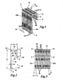
FIG. 1 is a perspective view of a strip of a plurality of fasteners for spacing an object from a substrate according to the present invention. -
FIG. 2 is a plan view of a fastener for spacing an object from a substrate according to the present invention. -
FIG. 3 is a side view of the strip of fasteners according to the present invention. -
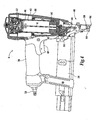
FIG. 4 is a partial side sectional view of a tool for installing the fasteners of the present invention. -
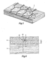
FIG. 5 is a perspective view of the fasteners of the present invention after being installed to hold and space wire lath at a predetermined distance from a substrate. -
FIG. 6 is a side sectional view of the fastener of the present invention after being installed, including a stucco layer being reinforced by wire lath. -
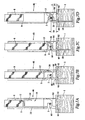
FIG. 7 is a side sectional view showing the progress of the fastener being installed to hold and space the wire lath at the predetermined distance from the substrate. - Referring to
FIGS. 2 and5 , afastener 10 is shown for spacing an object, such aswire lath 2, at a predetermined distance from asubstrate 1.Novel fastener 10 includes abridge portion 12, along prong 18 extending in a driving direction frombridge portion 12, and ashort prong 20 spaced fromlong prong 18 extending generally parallel tolong prong 18 in the driving direction frombridge portion 12, whereinshort prong 20 is substantially shorter thanlong prong 18. Preferably,bridge portion 12,long prong 18, andshort prong 20 are all straight-line segments, whereinshort prong 20 andlong prong 18 are generally perpendicular to bridgeportion 12. In one embodiment, the length SL ofshort prong 20 is between about 75% and about 99% of the length BL ofbridge portion 12 and the length SL ofshort prong 20 is between about 25% and about 45% of the length LL oflong prong 18. - Turning to
FIGS. 5 and 6 , fastener orclip 10 is used for holding and spacing an object, preferably a wire object, at a predetermined distance SD from asubstrate 1. For example,substrate 1 can be wood, plywood, particle board, oriented strand board (OSB board) or other wooden substrates, andclip 10 can be used to space a sheet ofwire lath 2, such as hexagonal or octagonal chicken wire, fromsubstrate 1 before applying one or more layers of plaster orstucco 4 tosubstrate 1. In this embodiment,wire lath 2 reinforcesstucco 4 to prevent it from breaking away fromsubstrate 1 afterstucco 4 has been applied. - It is preferred that
wire lath 2 be spaced fromsubstrate 1 by a predetermined distance SD so thatwire lath 2 will be embedded generally in the middle ofstucco 4, as shown inFIG. 6 , to most effectively reinforcestucco 4.Clip 10 fastenswire lath 2 tosubstrate 1, as described below, so thatwire lath 2 is spaced fromsubstrate 1 by predetermined distance SD. In one embodiment,wire lath 2 is spaced fromsubstrate 1 by a predetermined distance SD of between about 1/8 inch (3.2 mm) and about 3/8 inch (9.6 mm), preferably between about ¼ inch (6.4 mm) and about 5/16 inch (8.00 mm). - Turning back to
FIG. 2 ,clip 10 is a generally J shaped wire member having abridge portion 12 with twoends 14, 1.6, along prong 18 extending in the driving direction from oneend 14 of bridge portion, and ashort prong 20 spaced fromlong prong 18 and extending generally parallel tolong prong 18 in the driving direction from theother end 16 ofbridge portion 12, wherein the length SL ofshort prong 20 is substantially shorter than the length LL oflong prong 18. -
Clip 10 should be made from a material that is strong enough to securely fastenwire lath 2 tosubstrate 1 and to supportwire lath 2 andstucco 4 under normal conditions to preventstucco 4 from breaking offsubstrate 1.Clip 10 can be made from steel used to make staples for the construction industry. The material ofclip 10 can be carbon steel, stainless steel, or other metals and alloys used to make wire staples. In one embodiment,clip 10 is made from carbon steel having a carbon content between 1008 carbon steel and 1065 carbon steel, wherein lower carbon content steel, such as 1008 steel, is used forsubstrates 1 that are soft, such as chip board, and higher carbon content steel, such as 1065 steel, is used forhard substrates 1, such as solid hard woods. The 10xx series of the Society of Automotive Engineers (SAE) includes plain carbon steels with no modification in the alleys and with 0.xx% carbon content.Clip 10 can be made from metal wire that has been shaped.Clip 10 may be made from carbon steel wire having a gauge between about 18 gauge and about 12 gauge, preferably about 16 gauge or about 14 gauge. In one embodiment,clip 10 is made from shaped 1018carbon steel 16 gauge wire. Preferably the wire is flattened so that the wire has a width W of about 0.05 inch (1,28 mm) and a thickness T of about 1/16 inch (1.60 mm). If a thicker clip is desired, 14 gauge steel wire may also be used. The Steel Gauge chart of SAE defines the thickness and the weight of steel. Thegauge number 12, as an example, is for a wire having a thickness of 0.1046 inches and a weight of 0.06 to 0.0986 pounds per square feet. -
Clip 10 is driven by afastener driving tool 6, described below.Bridge portion 12 ofclip 10 is impacted by adriver blade 8 oftool 6 so thatclip 10 is driven intosubstrate 1, seeFIGS. 7A-7D .Bridge portion 12 has a profile that complements the profile of a drivingend 9 ofdriver blade 8 so thatclip 10 is driven straight and evenly intosubstrate 1. In one embodiment, drivingend 9 ofdriver blade 8 has a generally rectangular profile with a generally planar driving surface (not shown) generally normal to the driving direction.Clip 10 has an extended, generallystraight bridge portion 12, seeFIG. 2 , that is also generally normal to the driving direction so that the driving surface, will contactbridge portion 12 evenly asclip 10 is driven. Preferably, length BL ofbridge portion 12 is approximately the same as the width of drivingend 9 ofdriver blade 8. - In one embodiment,
bridge portion 12,long prong 18, andshort prong 20 are generally straight-line segments wherein prongs 18, 20 are generally perpendicular to bridgeportion 12, as shown inFIG. 2 . Preferably,bridge portion 12,long prong 18, andshort prong 20 are straight-lined segments that are all generally in the same plane, as is best seen inFIG. 1 . -
Short prong 20 andlong prong 18 extend frombridge portion 12 so that they are generally parallel to each other. In the embodiment shown inFIG. 2 ,short prong 20 extends from oneend 16 ofbridge portion 12 andlong prong 18 extends from theother end 14 ofbridge portion 12. Prongs 18, 20 preferably both extend generally in the driving direction ofdriver blade 8 so that bothshort prong 20 andlong prong 18 are generally parallel to each other and generally perpendicular to bridgeportion 12. - Preferably, the
juncture 22 betweenlong prong 18 andbridge portion 12 and thejuncture 24 betweenshort prong 20 andbridge portion 12 are curved, as shown inFIG. 2 , so that there is a smooth transition betweenbridge portion 12 andprongs Curved junctures junctures prongs clip 10. In one embodiment,junctures - In one embodiment,
long prong 18 extends fromend 14 ofbridge portion 12 to adistal end 26 having apoint 28 andshort prong 20 extends from theopposite end 16 ofbridge portion 12 to adistal end 30 having apoint 32. In one embodiment,long prong point 28 forms an angle α andshort prong point 32 forms an angle β, wherein the tips ofpoints prongs - The length LL of
long prong 18 is substantially longer than the length SL ofshort prong 20 so that whenclip 10 is installed,wire lath 2 will be spaced fromsubstrate 1 by predetermined distance SD. Long prong length LL is selected so that enough oflong prong 18 is embedded insubstrate 1 to securely fastenclip 10 andwire lath 2 to substrate while still having enough oflong prong 18 protruding fromsubstrate 1 tospace wire lath 2 fromsubstrate 1 by predetermined distance SD. - Length SL of
short prong 20 is substantially shorter than long prong length LL. It is preferred that short prong length SL be shorter than the length BL ofbridge portion 12 so that whenshort prong 20 is bent during driving, as described below, it is not interfered with bylong prong 18, but rather bends enough to securely holdwire lath 2 betweenshort prong 20 andbridge portion 12, as shown inFIGS. 6 and7D . - In one embodiment, short prong length SL is between about 25% and about 45%, preferably about 35% of long prong length LL and between about 75% and about 99%, preferably about 87% of bridge portion length BL. For the application of holding and
spacing wire lath 2 fromsubstrate 1,bridge portion 12 can have a length BL, of between about 1/6 inch (1.60 mm) and about 1-1/2 inch (2,56-1.28 mm), preferably between about 3/16 inch (4.8 mm) known as a narrow crown clip, and about 15/16 inch (2.40 mm), known as a wide crown clip, still more preferably about ½ inch (1.28 mm), known as a standard crown clip,short prong 20 can have a length SL between about 5/32 inch (4 mm) and about 13/16 inch (2.08 mm), preferably between about ¼ inch (6.4 mm) and about 5/8 inch (16 mm), still more preferably about 7/16 inch (11.2 mm) andlong prong 18 has a length LL of between about 1 inch (2.56 mm) and about 2 inch (5.12 mm), preferably between about 1-1/8 inch (2.88 cm) and about 1-½ inch (3.84 cm), still more preferably about 1-¼ inch (3.20 cm). - Turning to
FIG. 1 , in a preferred embodiment of the present invention, a ' plurality ofclips 10 are arranged in astrip 34 so that a plurality ofclips 10 can easily be fed totool 6.Strip 34 includes a plurality ofclips 10 connected together in a side-by-side array, as shown inFIG. 1 , wherein eachclip 10 includes abridge portion 12, seeFIG. 1 , along prong 18 extending in a driving direction frombridge portion 12, and ashort prong 20 spaced fromlong prong 18 and extending generally parallel tolong prong 18 in the driving direction frombridge portion 12, whereinshort prong 20 is substantially shorter thanlong prong 18. Each one of thelong prongs 18 is aligned generally in a common plane ABCD and each one of theshort prongs 20 are aligned generally in a common plane EFGH (seeFIGS. 1 and 3 ) so as to formstrip 34 ofclips 10. - Preferably, clips 10 are releasably connected together so that they do not break apart during normal handling of
strip 34 andtool 6, but rather are broken apart whendriver blade 8 sheers afirst clip 10 away from the rest ofstrip 34 and drives theclip 10 towardsubstrate 1.Clips 10 can be connected together with welding, microwelding, adhesives, and other means of fastening or cohering a plurality ofclips 10 together in the side-by-side array shown inFIGS. 1 and 3 . In one embodiment, clips 10 are connected together with an adhesive, each one of thebridge portions 12 are generally straight and eachbridge portion 12 is aligned generally in a common plane CDEH, wherein plane CDEH ofbridge portions 12 is generally perpendicular to plane ABCD oflong prongs 18 and plane EFGH ofshort prongs 20 so that clips 10 ofstrip 34 are generally aligned with one another. Preferably,long prong 18,short prong 20, andbridge portion 12 of each of the plurality ofclips 10 are generally straight-line segments that are generally in the same plane, such as plane ADEF shown inFIG. 1 , and the planes of each of theclips 10 instrip 34 are substantially parallel to each other, such as plane ADEF ofclip 10a being generally parallel to plane BCHG ofclip 10b, as shown inFIGS. 1 and 3 . - In one method,
strip 34 is manufactured in a multi-wire operation, wherein a plurality of wires (not shown) are pulled at the same time so that the wires are running concurrently. The plurality of wires are pulled together so that they form a sheet of wires, wherein they are connected together by an adhesive material, such as a nitrocellulose adhesive; that adheres adjacent wires together. Examples of adhesives that can be used are described inU.S. Patent 5,441,373 , assigned to the assignee of this application, the disclosure of which is incorporated herein by reference. The adhesive is allowed to dry and cool to room temperature before the pre-adhered wire is punched into the shape ofstrip 34 ofclips 10. In one method, the wires are round, 16 gauge, 1018 carbon steel that are flattened in a flattening mill before the wires are pulled together so that each wire has a generally rectangular cross section. - Turning to
FIGS. 4 and7A-7D ,clip 10 is installed by afastener driving tool 6 having ahousing 36 with ahandle 38 depending generally from a trailing end ofhousing 36 for an operator to holdtool 6. Atrigger 40 is mounted to handle 38 foractuating tool 6. Acylinder 42 is located within housing 3 6, with apiston 44 withincylinder 42.
Driver blade 8 is coupled topiston 44 so that whenpiston 44 is driven in a driving direction throughcylinder 42, so isdriver blade 8. Anosepiece 46 is coupled to driving end ofhousing 36, whereinnosepiece 46 includes achannel 48 for guidingdriver blade 8 andclip 10 towardsubstrate 1. - A power source, such as pneumatic power, gas combustion, or explosive powder is used to drive
piston 44 anddriver blade 8 in the driving direction towardclip 10. In one embodiment,tool 6 includes anair connection 50 for connecting to a compressed air source (not shown), which feeds into achamber 52 in the trailing direction ofpiston 44. Whentrigger 40 is pulled by an operator, air pressure is increased inchamber 52, which drivespiston 44 towardclip 10.Tool 6 can also include abuffer 54 generally at the driving end ofcylinder 42 to protectpiston 44 andtool 6 from damage due to high speed impact. - Preferably,
tool 6 includes amagazine 56 for feeding astrip 34 ofclips 10 intochannel 48.Strip 34 is fed intomagazine 56 oftool 6 so that a first clip is withinchannel 48. Whentool 6 is fired, the first clip is broken away from an adjacent second clip bydriver blade 8 so that the first clip is driven towardsubstrate 1.Tool 6 can also include a follower (not shown) which biases strip 34 towardchannel 48, so that when the first clip is driven, the follower biases the second clip intochannel 48. - Continuing with
FIG. 4 ,tool 6 can also include adrive probe 58 that is operationally connected to a triggering mechanism (not shown), so thattool 6 cannot be fired withoutdrive probe 58 being pushed againstsubstrate 1, forcingdrive probe 58 in the trailing direction, enabling actuation oftool 6. - In a preferred embodiment, shown in
FIGS. 7A-7D ,nosepiece 46 includes a laterally extendingslot 60 for receiving andpositioning wire lath 2 relative to whereclip 10 will be driven and ananvil 62 with aramp 64 positioned withinchannel 48 betweenslot 60 and asubstrate contacting surface 66 for bendingshort prong 20 inwardly towardlong prong 18. - In order to hold and
space wire lath 2 at a predetermined distance SD fromsubstrate 1,wire lath 2 is positioned proximate tosubstrate 1 andtool 6 is positioned so thatwire lath 2 will be betweenprongs clip 10 is driven. In a preferred method,wire lath 2 is positioned withinslot 60, as shown inFIG. 7A , which positionswire lath 2 where it can be held betweenshort prong 20 andbridge portion 12. - As
clip 10 is driven bydriver blade 8,long prong 18 is driven straight intosubstrate 1 and acts to securely fastenclip 10 tosubstrate 1.Ramp 64 interferes with the path ofshort prong 20, as shown inFIGS. 7A-7D , so that the force ofdriver blade 8 forcesshort prong 20 to be bent byramp 64. Asshort prong 20 is directed inwardly towardlong prong 18, it holds or gripswire lath 2 betweenshort prong 20 andbridge portion 12 so thatwire lath 2 is held byclip 10. -
Ramp 64 is situated within channel so thatlong prong 18 will not encounterramp 64, but rather will continue to be driven intosubstrate 1 bydriver blade 8. Asshort prong 20 is being bent,long prong 18 is driven to a predetermined depth intosubstrate 1. The depth whichclip 10 is driven intosubstrate 1 is determined bynosepiece 46. Nosepiece also includes asubstrate contacting surface 66 that is pressed againstsubstrate 1 before drivingclip 10.Ramp 64 is spaced fromsubstrate contacting surface 66 by a predetermined distance DN which is approximately equal to the desired spacing distance SD ofwire lath 2 fromsubstrate 1. The selected distance DN between nosepiecesubstrate contacting surface 66 andramp 64 determines the position whereshort prong 20 will be bent in relation tosubstrate 1, which in turn determines wherewire lath 2 will be held relative tosubstrate 1.
Claims (9)
- A fastener for holding and spacing an object (2) at a predetermined distance from a substrate (1) comprising:a bridge portion (12);a first prong (18) extending in a driving direction from said bridge portion; anda second prong (20) spaced from said first prong and extending generally parallel thereto in the driving direction from said bridge portion (12);wherein said second prong (20) is substantially shorter than said first prong (18),said bridge portion (12), said first prong (18) and said second prong (20) are generally straight-line segments and said first prong (18) and said second prong (20) are generally perpendicular to said bridge portion (12), characterized in thatsaid second shorter prong (20) is shorter than said bridge portion (12) and said second shorter prong (20) and said bridge portion (12) are arranged so that said second shorter prong (20) can be bent and directed inwardly toward said first long prong (18) but without being interfered with by said first long prong (18), in order to securily hold the object (2) between said second shorter prong (20) and said bridge portion (12).
- A fastener according to claim 1, wherein the length of said second prong (20) is between about 25% and about 45% of the length of said first prong (18).
- A fastener according to claim 1, wherein the length of said second prong (20) is between about 75% and about 99% of the length of said bridge portion (12).
- A fastener according to claim 1, wherein said bridge portion (12) has a length of about ½inch (1.28 cm), said first prong (18) has a length of about 1-¼ inch (3.2 cm) and said second prong (20) has a length of about 7/16 inch (1.12 cm).
- A fastener according to claim 1, wherein said fastener is made from a shaped wire.
- A fastener according to claim 5, wherein said shaped wire has a thickness of about 0.05 inch (1.28 mm) and a thickness of about 1/16 inch (1.60 mm).
- A fastener according to claim 1, wherein said fastener is made form shaped 1018 carbon steel wire.
- A fastener according to claim 7, wherein said shaped wire has a thickness of about 0.05 inch (1.28 mm) and a thickness of about 1/16 inch (1.60 mm).
- A fastener according to claim 1, wherein said fastener is made form shaped 1018 carbon steel wire.
Applications Claiming Priority (2)
| Application Number | Priority Date | Filing Date | Title |
|---|---|---|---|
| US10/658,251 US6918222B2 (en) | 2003-09-09 | 2003-09-09 | Fastener for spacing object from substrate |
| US658251 | 2003-09-09 |
Publications (2)
| Publication Number | Publication Date |
|---|---|
| EP1514977A1 EP1514977A1 (en) | 2005-03-16 |
| EP1514977B1 true EP1514977B1 (en) | 2009-07-29 |
Family
ID=34136736
Family Applications (1)
| Application Number | Title | Priority Date | Filing Date |
|---|---|---|---|
| EP04292146A Active EP1514977B1 (en) | 2003-09-09 | 2004-09-07 | Fastener for spacing object from substrate |
Country Status (7)
| Country | Link |
|---|---|
| US (1) | US6918222B2 (en) |
| EP (1) | EP1514977B1 (en) |
| JP (1) | JP4842526B2 (en) |
| AU (1) | AU2004208719B2 (en) |
| CA (1) | CA2475479C (en) |
| DE (1) | DE602004022228D1 (en) |
| NZ (1) | NZ535175A (en) |
Cited By (1)
| Publication number | Priority date | Publication date | Assignee | Title |
|---|---|---|---|---|
| WO2011041825A1 (en) * | 2009-10-05 | 2011-04-14 | Christopher John Lacy | Apparatus and methods for inserting a fastener |
Families Citing this family (27)
| Publication number | Priority date | Publication date | Assignee | Title |
|---|---|---|---|---|
| US7410137B2 (en) * | 2003-08-18 | 2008-08-12 | At&T Delaware Intellectual Property, Inc. | Support device |
| US7077612B1 (en) * | 2003-08-22 | 2006-07-18 | Bellsouth Intellectual Property Corp. | Split p-hook |
| US6986448B2 (en) * | 2003-09-09 | 2006-01-17 | Illinois Tool Works Inc. | Fastener driving tool for spacing object from substrate |
| US7014087B1 (en) | 2003-10-16 | 2006-03-21 | Bellsouth Intellectual Property Corporation | Support guide for powder driver barrel |
| US7665063B1 (en) | 2004-05-26 | 2010-02-16 | Pegasystems, Inc. | Integration of declarative rule-based processing with procedural programming |
| US8335704B2 (en) | 2005-01-28 | 2012-12-18 | Pegasystems Inc. | Methods and apparatus for work management and routing |
| US8924335B1 (en) | 2006-03-30 | 2014-12-30 | Pegasystems Inc. | Rule-based user interface conformance methods |
| US8250525B2 (en) | 2007-03-02 | 2012-08-21 | Pegasystems Inc. | Proactive performance management for multi-user enterprise software systems |
| US8469645B2 (en) * | 2008-03-14 | 2013-06-25 | Lawrence J. Dichiera | Pneumatic fastener for metal studs and related method |
| US8843435B1 (en) | 2009-03-12 | 2014-09-23 | Pegasystems Inc. | Techniques for dynamic data processing |
| US8468492B1 (en) | 2009-03-30 | 2013-06-18 | Pegasystems, Inc. | System and method for creation and modification of software applications |
| US8880487B1 (en) | 2011-02-18 | 2014-11-04 | Pegasystems Inc. | Systems and methods for distributed rules processing |
| US9206608B2 (en) * | 2011-05-23 | 2015-12-08 | Abraham Gevorgian | Wall lath securing system |
| US9195936B1 (en) | 2011-12-30 | 2015-11-24 | Pegasystems Inc. | System and method for updating or modifying an application without manual coding |
| US9322493B2 (en) | 2013-04-08 | 2016-04-26 | Mark R. Wolff | Cable fastener with hook structure for supporting a cable |
| US9573260B2 (en) * | 2013-05-08 | 2017-02-21 | Arthur R. Walters, JR. | Fastening device for driving double-headed fasteners |
| DE102013011804B4 (en) * | 2013-07-16 | 2016-05-19 | Baussmann Collated Fasteners Gmbh | clamp rod |
| US20150107081A1 (en) * | 2013-10-19 | 2015-04-23 | Halex/Scott Fetzer Company | Angled fastener driving device |
| US10247329B2 (en) | 2014-04-04 | 2019-04-02 | Mark R. Wolff | Cable fastener with hook structure for supporting a cable |
| US9692214B2 (en) | 2014-04-04 | 2017-06-27 | Mark Richard Wolff | Dispenser for cable support and method |
| CA2903691C (en) * | 2014-09-08 | 2022-09-20 | Gary R. Johnson | Lath stapling system |
| US10469396B2 (en) | 2014-10-10 | 2019-11-05 | Pegasystems, Inc. | Event processing with enhanced throughput |
| US10698599B2 (en) | 2016-06-03 | 2020-06-30 | Pegasystems, Inc. | Connecting graphical shapes using gestures |
| US10698647B2 (en) | 2016-07-11 | 2020-06-30 | Pegasystems Inc. | Selective sharing for collaborative application usage |
| US10773367B2 (en) * | 2018-04-30 | 2020-09-15 | Everwin Pneumatic Corporation | Nail blocking member for nail gun |
| US11048488B2 (en) | 2018-08-14 | 2021-06-29 | Pegasystems, Inc. | Software code optimizer and method |
| US11567945B1 (en) | 2020-08-27 | 2023-01-31 | Pegasystems Inc. | Customized digital content generation systems and methods |
Family Cites Families (40)
| Publication number | Priority date | Publication date | Assignee | Title |
|---|---|---|---|---|
| US324126A (en) * | 1885-08-11 | Edwaed j | ||
| US312460A (en) * | 1885-02-17 | Staple | ||
| US256488A (en) * | 1882-04-18 | Sumner leonard | ||
| US401343A (en) * | 1889-04-16 | Electric-wire nail | ||
| US717554A (en) * | 1900-12-14 | 1903-01-06 | Richard Sedgwick | Carpet-fastener. |
| US1087262A (en) * | 1913-02-06 | 1914-02-17 | William Schildwachter | Well-tool. |
| US1546522A (en) * | 1923-01-02 | 1925-07-21 | George F Voight | Wall construction |
| US1610082A (en) * | 1923-03-21 | 1926-12-07 | Walter B Francis | Fastener |
| US1607954A (en) * | 1923-05-09 | 1926-11-23 | Fred Starr | Spacing and fastening device |
| GB222942A (en) * | 1923-07-09 | 1924-10-09 | British Electrical & Allied In | Improvements in electric circuit breakers and the like |
| US1590003A (en) * | 1923-10-13 | 1926-06-22 | George F Voight | Wall sheathing |
| US1703557A (en) * | 1923-12-26 | 1929-02-26 | John L Sullivan | Furring and fastening device |
| US2034726A (en) * | 1925-11-30 | 1936-03-24 | Margaret Domers | Reenforcement foundation |
| US1816387A (en) * | 1925-12-10 | 1931-07-28 | Menninger Elmore William | Furring construction |
| US1703560A (en) * | 1927-09-22 | 1929-02-26 | Economy Products Corp | Lath-spacing nail |
| US1877274A (en) * | 1928-04-09 | 1932-09-13 | Crowhurst Frank Scott | Building construction |
| US1801400A (en) * | 1929-09-05 | 1931-04-21 | Frederick M Venzie | Building structure |
| US1822781A (en) * | 1930-03-29 | 1931-09-08 | Mcskimming James | Wire spacing and fastening device |
| US1957467A (en) * | 1931-08-05 | 1934-05-08 | Menninger Elmore William | Spacer nail |
| US1957476A (en) * | 1931-10-14 | 1934-05-08 | Elgan S Sloan | Swiveled drill bit for cable tool drilling |
| US2314481A (en) * | 1941-07-05 | 1943-03-23 | Spotnails | Finishing nail |
| US2589491A (en) * | 1946-07-31 | 1952-03-18 | Charles B Goodstein | Staple setting apparatus and method |
| US2521019A (en) * | 1948-01-17 | 1950-09-05 | Richard A Percoco | Staple |
| US2533062A (en) * | 1948-12-20 | 1950-12-05 | Edward J Spink | Staple nail |
| US2887004A (en) * | 1954-11-04 | 1959-05-19 | William H Stewart | Staple having flat depressed head with reinforcing ridge |
| US3339448A (en) * | 1964-06-25 | 1967-09-05 | Powers Wire Products Company I | Fastener for furring articles from a supporting surface |
| US3339265A (en) * | 1964-10-22 | 1967-09-05 | Powers Wire Products Co Inc | Fastener driving and reforming tool for furring stucco-netting and the like |
| US3741068A (en) | 1972-01-03 | 1973-06-26 | J Andruskiewicz | Wallboard staple |
| JPS5438666B2 (en) * | 1973-03-27 | 1979-11-22 | ||
| DE2829697C2 (en) * | 1978-07-06 | 1986-10-30 | Henkel KGaA, 4000 Düsseldorf | Detergent composition |
| US4257200A (en) * | 1979-05-21 | 1981-03-24 | Hensley Clifford A | Cotton module tarpaulin pin |
| DE3422841A1 (en) * | 1983-06-29 | 1985-01-03 | Friedrich Trurnit GmbH & Co KG Drahtstifte- und Metallwaren-Fabrik Kunststoffverarbeitung, 5990 Altena | Hook nail |
| EP0314831A1 (en) * | 1987-11-06 | 1989-05-10 | Joh. Friedrich Behrens AG | Strip of fastenings and hammering tool for hammering the fastenings of the strip of fastenings |
| DE4011778C2 (en) * | 1989-09-08 | 1995-06-01 | Hitachi Koki Kk | Pneumatic impact tool for fasteners |
| US5484094A (en) | 1994-06-16 | 1996-01-16 | Illinois Tool Works Inc. | Workpiece-contacting probe for fastener-driving tool for fastening lath to substrate |
| JPH10152965A (en) * | 1996-11-20 | 1998-06-09 | Sumitomo Forestry Co Ltd | Staple and driving tool thereof |
| US6237827B1 (en) | 1998-11-12 | 2001-05-29 | Senco Products, Inc. | Stapler and method for the attachment of steel framing |
| US6363679B1 (en) | 1999-06-11 | 2002-04-02 | Flannery, Inc. | Fastening device |
| US6481613B1 (en) | 2000-02-16 | 2002-11-19 | Glenn J. Tebo | Fastener driving device |
| US6957756B2 (en) * | 2002-04-10 | 2005-10-25 | Illinois Tool Works Inc. | Tool with nosepiece for bending fastener upon installation and fastener therefor |
-
2003
- 2003-09-09 US US10/658,251 patent/US6918222B2/en not_active Expired - Lifetime
-
2004
- 2004-07-22 CA CA002475479A patent/CA2475479C/en active Active
- 2004-08-23 JP JP2004242718A patent/JP4842526B2/en not_active Expired - Fee Related
- 2004-09-03 AU AU2004208719A patent/AU2004208719B2/en active Active
- 2004-09-07 EP EP04292146A patent/EP1514977B1/en active Active
- 2004-09-07 DE DE602004022228T patent/DE602004022228D1/en active Active
- 2004-09-08 NZ NZ535175A patent/NZ535175A/en unknown
Cited By (3)
| Publication number | Priority date | Publication date | Assignee | Title |
|---|---|---|---|---|
| WO2011041825A1 (en) * | 2009-10-05 | 2011-04-14 | Christopher John Lacy | Apparatus and methods for inserting a fastener |
| CN102712082A (en) * | 2009-10-05 | 2012-10-03 | 克里斯托弗·约翰·拉丝 | Apparatus and methods for inserting a fastener |
| CN102712082B (en) * | 2009-10-05 | 2016-03-16 | 克里斯托弗·约翰·拉丝 | The insertion apparatus of securing member and method |
Also Published As
| Publication number | Publication date |
|---|---|
| US20050053448A1 (en) | 2005-03-10 |
| AU2004208719B2 (en) | 2007-03-22 |
| JP2005083576A (en) | 2005-03-31 |
| CA2475479A1 (en) | 2005-03-09 |
| DE602004022228D1 (en) | 2009-09-10 |
| CA2475479C (en) | 2007-11-20 |
| AU2004208719A1 (en) | 2005-03-24 |
| US6918222B2 (en) | 2005-07-19 |
| JP4842526B2 (en) | 2011-12-21 |
| NZ535175A (en) | 2006-03-31 |
| EP1514977A1 (en) | 2005-03-16 |
Similar Documents
| Publication | Publication Date | Title |
|---|---|---|
| EP1514977B1 (en) | Fastener for spacing object from substrate | |
| US7011242B2 (en) | Coated staple and fastening tool for the same | |
| CA2419363C (en) | Tool with nosepiece for bending fastener upon installation and fastener therefor | |
| US8322010B2 (en) | Fastening tool with modified driver travel path | |
| US6139238A (en) | Fastener for laminate flooring | |
| US9360036B2 (en) | Fastener assembly | |
| US6986448B2 (en) | Fastener driving tool for spacing object from substrate | |
| AU716431B2 (en) | Angled chisel point brad and method therefor | |
| GB2078894A (en) | Nails | |
| US6000893A (en) | Angled strip of brads and method therefor | |
| US8844785B2 (en) | Powered stapler and method of operating same | |
| US9091289B2 (en) | Angular nail stick with mucilage connection system | |
| WO2004085119A2 (en) | Power tool for metal piercing fasteners |
Legal Events
| Date | Code | Title | Description |
|---|---|---|---|
| PUAI | Public reference made under article 153(3) epc to a published international application that has entered the european phase |
Free format text: ORIGINAL CODE: 0009012 |
|
| AK | Designated contracting states |
Kind code of ref document: A1 Designated state(s): AT BE BG CH CY CZ DE DK EE ES FI FR GB GR HU IE IT LI LU MC NL PL PT RO SE SI SK TR |
|
| AX | Request for extension of the european patent |
Extension state: AL HR LT LV MK |
|
| 17P | Request for examination filed |
Effective date: 20050907 |
|
| AKX | Designation fees paid |
Designated state(s): DE FR GB |
|
| 17Q | First examination report despatched |
Effective date: 20080610 |
|
| GRAP | Despatch of communication of intention to grant a patent |
Free format text: ORIGINAL CODE: EPIDOSNIGR1 |
|
| GRAS | Grant fee paid |
Free format text: ORIGINAL CODE: EPIDOSNIGR3 |
|
| GRAA | (expected) grant |
Free format text: ORIGINAL CODE: 0009210 |
|
| AK | Designated contracting states |
Kind code of ref document: B1 Designated state(s): DE FR GB |
|
| REG | Reference to a national code |
Ref country code: GB Ref legal event code: FG4D |
|
| REF | Corresponds to: |
Ref document number: 602004022228 Country of ref document: DE Date of ref document: 20090910 Kind code of ref document: P |
|
| PLBE | No opposition filed within time limit |
Free format text: ORIGINAL CODE: 0009261 |
|
| STAA | Information on the status of an ep patent application or granted ep patent |
Free format text: STATUS: NO OPPOSITION FILED WITHIN TIME LIMIT |
|
| 26N | No opposition filed |
Effective date: 20100503 |
|
| REG | Reference to a national code |
Ref country code: FR Ref legal event code: PLFP Year of fee payment: 12 |
|
| REG | Reference to a national code |
Ref country code: FR Ref legal event code: PLFP Year of fee payment: 13 |
|
| REG | Reference to a national code |
Ref country code: FR Ref legal event code: PLFP Year of fee payment: 14 |
|
| REG | Reference to a national code |
Ref country code: FR Ref legal event code: PLFP Year of fee payment: 15 |
|
| P01 | Opt-out of the competence of the unified patent court (upc) registered |
Effective date: 20230606 |
|
| PGFP | Annual fee paid to national office [announced via postgrant information from national office to epo] |
Ref country code: GB Payment date: 20230927 Year of fee payment: 20 |
|
| PGFP | Annual fee paid to national office [announced via postgrant information from national office to epo] |
Ref country code: FR Payment date: 20230925 Year of fee payment: 20 Ref country code: DE Payment date: 20230927 Year of fee payment: 20 |