EP1514435B1 - Fail-safe coupling of a network element to a communication network - Google Patents
Fail-safe coupling of a network element to a communication network Download PDFInfo
- Publication number
- EP1514435B1 EP1514435B1 EP03735612A EP03735612A EP1514435B1 EP 1514435 B1 EP1514435 B1 EP 1514435B1 EP 03735612 A EP03735612 A EP 03735612A EP 03735612 A EP03735612 A EP 03735612A EP 1514435 B1 EP1514435 B1 EP 1514435B1
- Authority
- EP
- European Patent Office
- Prior art keywords
- packet
- communication network
- network element
- connection
- network
- Prior art date
- Legal status (The legal status is an assumption and is not a legal conclusion. Google has not performed a legal analysis and makes no representation as to the accuracy of the status listed.)
- Expired - Fee Related
Links
Images
Classifications
-
- H—ELECTRICITY
- H04—ELECTRIC COMMUNICATION TECHNIQUE
- H04Q—SELECTING
- H04Q3/00—Selecting arrangements
- H04Q3/64—Distributing or queueing
- H04Q3/66—Traffic distributors
-
- H—ELECTRICITY
- H04—ELECTRIC COMMUNICATION TECHNIQUE
- H04L—TRANSMISSION OF DIGITAL INFORMATION, e.g. TELEGRAPHIC COMMUNICATION
- H04L45/00—Routing or path finding of packets in data switching networks
- H04L45/22—Alternate routing
-
- H—ELECTRICITY
- H04—ELECTRIC COMMUNICATION TECHNIQUE
- H04L—TRANSMISSION OF DIGITAL INFORMATION, e.g. TELEGRAPHIC COMMUNICATION
- H04L45/00—Routing or path finding of packets in data switching networks
- H04L45/24—Multipath
-
- H—ELECTRICITY
- H04—ELECTRIC COMMUNICATION TECHNIQUE
- H04L—TRANSMISSION OF DIGITAL INFORMATION, e.g. TELEGRAPHIC COMMUNICATION
- H04L45/00—Routing or path finding of packets in data switching networks
- H04L45/58—Association of routers
- H04L45/586—Association of routers of virtual routers
-
- H—ELECTRICITY
- H04—ELECTRIC COMMUNICATION TECHNIQUE
- H04L—TRANSMISSION OF DIGITAL INFORMATION, e.g. TELEGRAPHIC COMMUNICATION
- H04L45/00—Routing or path finding of packets in data switching networks
- H04L45/24—Multipath
- H04L45/247—Multipath using M:N active or standby paths
-
- H—ELECTRICITY
- H04—ELECTRIC COMMUNICATION TECHNIQUE
- H04M—TELEPHONIC COMMUNICATION
- H04M3/00—Automatic or semi-automatic exchanges
- H04M3/08—Indicating faults in circuits or apparatus
-
- H—ELECTRICITY
- H04—ELECTRIC COMMUNICATION TECHNIQUE
- H04M—TELEPHONIC COMMUNICATION
- H04M7/00—Arrangements for interconnection between switching centres
- H04M7/12—Arrangements for interconnection between switching centres for working between exchanges having different types of switching equipment, e.g. power-driven and step by step or decimal and non-decimal
- H04M7/1205—Arrangements for interconnection between switching centres for working between exchanges having different types of switching equipment, e.g. power-driven and step by step or decimal and non-decimal where the types of switching equipement comprises PSTN/ISDN equipment and switching equipment of networks other than PSTN/ISDN, e.g. Internet Protocol networks
- H04M7/125—Details of gateway equipment
- H04M7/1255—Details of gateway equipment where the switching fabric and the switching logic are decomposed such as in Media Gateway Control
-
- H—ELECTRICITY
- H04—ELECTRIC COMMUNICATION TECHNIQUE
- H04Q—SELECTING
- H04Q2213/00—Indexing scheme relating to selecting arrangements in general and for multiplex systems
- H04Q2213/13141—Hunting for free outlet, circuit or channel
-
- H—ELECTRICITY
- H04—ELECTRIC COMMUNICATION TECHNIQUE
- H04Q—SELECTING
- H04Q2213/00—Indexing scheme relating to selecting arrangements in general and for multiplex systems
- H04Q2213/13145—Rerouting upon failure
-
- H—ELECTRICITY
- H04—ELECTRIC COMMUNICATION TECHNIQUE
- H04Q—SELECTING
- H04Q2213/00—Indexing scheme relating to selecting arrangements in general and for multiplex systems
- H04Q2213/13166—Fault prevention
-
- H—ELECTRICITY
- H04—ELECTRIC COMMUNICATION TECHNIQUE
- H04Q—SELECTING
- H04Q2213/00—Indexing scheme relating to selecting arrangements in general and for multiplex systems
- H04Q2213/13167—Redundant apparatus
-
- H—ELECTRICITY
- H04—ELECTRIC COMMUNICATION TECHNIQUE
- H04Q—SELECTING
- H04Q2213/00—Indexing scheme relating to selecting arrangements in general and for multiplex systems
- H04Q2213/13196—Connection circuit/link/trunk/junction, bridge, router, gateway
-
- H—ELECTRICITY
- H04—ELECTRIC COMMUNICATION TECHNIQUE
- H04Q—SELECTING
- H04Q2213/00—Indexing scheme relating to selecting arrangements in general and for multiplex systems
- H04Q2213/13292—Time division multiplexing, TDM
-
- H—ELECTRICITY
- H04—ELECTRIC COMMUNICATION TECHNIQUE
- H04Q—SELECTING
- H04Q2213/00—Indexing scheme relating to selecting arrangements in general and for multiplex systems
- H04Q2213/1338—Inter-exchange connection
-
- H—ELECTRICITY
- H04—ELECTRIC COMMUNICATION TECHNIQUE
- H04Q—SELECTING
- H04Q2213/00—Indexing scheme relating to selecting arrangements in general and for multiplex systems
- H04Q2213/13389—LAN, internet
Definitions
- TDM Time Division Multiplex, time division multiplex
- IP Internet Protocol
- the failures to be considered include partial failures in the media gateway, total failures or partial failures of IP routers and failures of connections between the media gateway and IP routers.
- a fail-safe connection of a media gateway to an IP router ensures an unrestricted function of the entire system if one of these failures occurs.
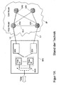
- FIGS. 1A and 1B Known possibilities for realizing fail-safe connections between a media gateway and IP routers are shown in FIGS. 1A and 1B.
- FIG. 1 shows, for example, a double existing Ethernet switch ES0, ES1, by means of which the switching or switching of the data between the media gateway MG and the IP network IP is carried out.
- one of the duplicate components is active, the other inactive.
- the first Ethernet switch ES0 is active and the second Ethernet switch ES1 is inactive.
- the operating state of an inactive component in this case, for example, the Ethernet switch ES1 is also referred to as standby or standby since this inactive component can immediately assume its tasks in the event of a failure of the active component.
- the amount of active components is below referred to as "active half", the set of inactive components as “inactive half”.
- the media gateway MG is connected to two edge routers ER0, ER1 of the IP network IP.
- the media gateway MG has a plurality of independent connections - in the example shown in FIG. 1A, these are two independent connections L0, L1.
- both the active and the inactive half of the media gateway MG via separate connections L0, L1 connected to the IP network IP.
- the first connection L0 connects the first active Ethernet switch ES0 to the first edge router ER0 of the IP network IP.
- the second connection L1 connects the second inactive Ethernet switch ES1 to the second edge router ER1 of the IP network IP.
- the first connection L0 is thus the active connection
- the second connection L1 is the inactive connection or standby connection.
- active and “inactive” refer to the transport and switching of user data, for example, an inactive connection is physically quite active, but transported no user data.
- an exemplary media gateway MG with 2000 (voice telephony) ports having a data rate of 64 kbps each and IP packets each carrying 10 ms of digitized voice data at approximately a data rate of 220 Mbps is interposed between the media gateway MG and the IP network IP, in the example of Figure 1 on the active connection L0 transferred.
- each half of the media gateway MG is connected to a respective router ER0, ER1 by means of one Gigabit Ethernet connection L0, L1 each.
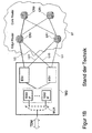
- each half of the media gateway MG is respectively connected to both routers ER0, ER1 by means of a total of four gigabit Ethernet connections L0, L1, L01, L10.
- the following compounds are additionally required compared with FIG. 1A: Connection L01 between the first Ethernet switch ES0 of the media gateway MG and the second edge router ER1 of the IP network IP; Connection L10 between the second Ethernet switch ES1 and the first edge router ER0.
- FIG. 1B for connecting the media gateway MG to the IP network IP only the first connection L0 is active, all further connections L1, L01, L10 are inactive connections or standby connections.
- connection rate related to the data rate increases greatly due to the lack of concentration capability at low utilization, e.g. 25% utilization of a connection results in 4 times the data rate related costs compared to 100% utilization of the same connection.
- a media gateway is also known, with a dual redundant running TDM component , which is connected to a TDM network and uses RAS / VOIP units to connect to a packet network.
- a method for fail-safe connection of a network element MG with at least one at least twice redundant component ES0, ES1 to a communication network IP, accordingly at least two interface units IF0, IF1, IF2, IF3 via one connection L0, L1, L2 , L3 are each coupled to a component ER0, ER1, ER2, ER3 of the communication network IP and via a respective connection to the redundant components ES0, ES1 of the network element MG.
- a network element MG is provided with fail-safe connection to a communication network IP with at least one at least two redundantly running component ES0, ES1, the at least two interface units IF0, IF1, IF2, IF3, each with a connection for connection to the communication network IP L0, L1, L2, L3 each have a component ER0, ER1, ER2, ER3 of the communication network IP and each having a connection to the redundant components ES0, ES1 of the network element MG.
- connection grouping is introduced here as the grouping of interface unit IF0, IF1, IF2, IF3, associated connection L0, L1, L2, L3 and associated component ER0, ER1, ER2, ER3 of the communication network IP, since these form a failure unit, ie From the point of view of the connection, the failure of an interface unit or the assigned connection or the assigned component of the communication network is equivalent.
- connection can be made with (N + 1) connection groupings, where N is as gives the minimum number of simultaneously required separate connections to provide the desired total transmission rate of the link.
- Another advantage of the invention is the fact that the present invention allows the distribution of a fail-safe connection to low-rate connections, for example 4 Fast Ethernet connections instead of 2 Gigabit Ethernet connection, and thus allows a cost-effective connection, as several low-rate connections usually cheaper are considered a high-rate, whose capacity, for example less than 30% is exhausted.
- Figures 1 and 2 each show a media gateway MG, which is connected on the one hand by means of TDM method to a conventional telephone network and on the other hand to be connected to a communication network IP.
- Figures 1A and 1B show, as already explained, various methods of the prior art for connecting a network element MG to a communication network IP.
- the communication network IP is, for example, a packet-oriented communication network.
- An important transmission protocol for packet-oriented networks is the Internet Protocol.
- the media gateway MG has, in addition to other components, not shown, a multiplexer MUX, are distributed with the TDM data to a plurality of TDM / IP converter TDM / IP. These converters are connected via internal connections of the media gateway MG to the Ethernet switches ES0, ES1. As already explained, one of the duplicate Ethernet switches ES0, ES1 is active and the other is inactive. In the example shown, the first Ethernet switch ES0 is active and the second Ethernet switch ES1 is inactive or in standby mode. Other - not shown - elements of the media gateway MG can also be duplicated to increase the resilience of the media gateway MG.
- the set of active elements is called the “active half” and the set of inactive elements is called the “inactive half”. Automatically when an active element fails or is controlled by administrative intervention, the associated inactive element is activated and takes over the role of the previously active element.
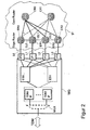
- FIG. 2 shows an exemplary embodiment of the inventive connection of a media gateway MG to the IP network IP.
- Four interface units IF0, IF1, IF2, IF3, which are part of the media gateway MG, are respectively connected to the active Ethernet switch ES0 and to the inactive Ethernet switch ES1 via internal connections of the media gateway MG.
- Each interface unit IF0, IF1, IF2, IF3 is assigned exactly one connection L0, L1, L2, L3 to the IP network IP, which the interface units IF0, IF1, IF2, IF3, each with an edge router ER0, ER1, ER2, ER3 of the IP network IP.
- Ethernet frames incoming from the edge router ER0, ER1, ER2, ER3 are duplicated and always forwarded to both Ethernet switches ES0, ES1, and the inactive Ethernet switch ES1 discards the incoming Ethernet frames.
- Ethernet frames arriving from the Ethernet switches ES0, ES1 are always forwarded to the edge routers ER0, ER1, ER2, ER3. In this case, it must be ensured that at any one time only one Ethernet switch ES0, ES1 is active, i. Sends data to the edge routers ER0, ER1, ER2, ER3.
- the payload is distributed to several links L0, L1, L2, L3, in Figure 2, for example, four Links.
- N + 1 4 Fast Ethernet type L0, L1, L2, L3 links (each with a capacity of 100Mbps) are used. Each of these connections L0, L1, L2, L3 is 55% utilized in trouble-free operation in this example. If an edge router ER0, ER1, ER2, ER or a connection L0, L1, L2, L3 fails, the affected payload is distributed over the free capacity of the remaining connections L0, L1, L2, L3, which are then utilized to 73% are.
- connections EL0, EL1, EL2 can be provided between the edge routers ER0, ER1, ER2, ER3 in order to prevent the failure of an interface unit IF0, IF1, IF2, IF3 or a connection L0, L1, L2, L3 Redirect this failed interface unit or connection assigned traffic to the edge router with functioning interface unit or connection.
- This (with respect to the edge router local) redirection of traffic takes place regularly faster than redirecting the traffic through the next router level, which is formed for example from core routers CR0, CR1.
- the invention has been described in connection with the connection of a media gateway MG to an IP network IP, the invention is not limited to the embodiment.
- the connection of a media gateway MG to other packet-oriented networks IP is possible with the present invention.
- the illustrated packet forks may operate based on frames from other Layer 2 protocols, or based on IP packets, or based on packets from other Layer 2 protocols.
Abstract
Description
Um die mit herkömmlichen TDM-Telefonnetzen (TDM=Time Division Multiplex, zeitmultiplex) erreichte hohe Verfügbarkeit des Telefoniedienstes auch bei Einsatz von IP-Netzen (IP=Internet Protocol) als Transportnetz zu gewährleisten, müssen Media-Gateways (Trunk-Gateways, Access-Gateways) ausfallsicher an ein Netz von IP-Routern angeschlossen werden.In order to ensure the high availability of the telephony service with conventional TDM telephone networks (TDM = Time Division Multiplex, time division multiplex) even when using IP networks (IP = Internet Protocol) as the transport network, media gateways (trunk gateways, access Gateways) fail-safe to be connected to a network of IP routers.
Die dabei zu berücksichtigenden Ausfälle umfassen Teilausfälle im Media-Gateway, Totalausfälle oder Teilausfälle von IP-Routern und Ausfälle der Verbindungen zwischen dem Media-Gateway und IP-Routern. Eine ausfallsichere Anbindung eines Media-Gateway an IP-Router gewährleistet eine unbeeinträchtige Funktion des Gesamtsystems, falls einer der genannten Ausfälle auftritt.The failures to be considered include partial failures in the media gateway, total failures or partial failures of IP routers and failures of connections between the media gateway and IP routers. A fail-safe connection of a media gateway to an IP router ensures an unrestricted function of the entire system if one of these failures occurs.
Bekannte Möglichkeiten zur Realisierung ausfallsicherer Verbindungen zwischen einem Media-Gateway und IP-Routern sind in den Figuren 1A und 1B dargestellt. Um Ausfälle von zentralen Komponenten innerhalb des Media-Gateway abzufangen, sind alle zentralen Komponenten des Media-Gateway MG doppelt vorhanden. In Figur 1 ist beispielsweise ein doppelt vorhandener Ethernet-Switch ES0, ES1 dargestellt, durch welchen das Switching bzw. die Vermittlung der Daten zwischen dem Media-Gateway MG und dem IP-Netz IP ausgeführt wird. Hierbei ist jeweils eine der doppelt vorhandenen Komponenten aktiv, die andere inaktiv. Im dargestellten Beispiel ist der erste Ethernet-Switch ES0 aktiv und der zweite Ethernet-Switch ES1 inaktiv. Der Betriebszustand einer inaktiven Komponente, hier beispielsweise des Ethernet-Switches ES1, wird auch als Standby bzw. Bereitschaft bezeichnet, da diese inaktive Komponente im Fall eines Ausfalls der aktiven Komponente sofort deren Aufgaben übernehmen kann. Die Menge der aktiven Komponenten wird im folgenden als "aktive Hälfte" bezeichnet, die Menge der inaktiven Komponenten als "inaktive Hälfte".Known possibilities for realizing fail-safe connections between a media gateway and IP routers are shown in FIGS. 1A and 1B. In order to intercept failures of central components within the media gateway, all central components of the media gateway MG are duplicated. FIG. 1 shows, for example, a double existing Ethernet switch ES0, ES1, by means of which the switching or switching of the data between the media gateway MG and the IP network IP is carried out. In this case, one of the duplicate components is active, the other inactive. In the example shown, the first Ethernet switch ES0 is active and the second Ethernet switch ES1 is inactive. The operating state of an inactive component, in this case, for example, the Ethernet switch ES1, is also referred to as standby or standby since this inactive component can immediately assume its tasks in the event of a failure of the active component. The amount of active components is below referred to as "active half", the set of inactive components as "inactive half".
Der Media-Gateway MG wird an zwei Edge-Router ER0, ER1 des IP-Netzes IP angeschlossen. Hierzu weist der Media-Gateway MG mehrere unabhängige Anschlüsse auf - im dargestellten Beispiel aus Figur 1A sind dies zwei unabhängige Verbindungen L0, L1. Dabei wird sowohl die aktive als auch die inaktive Hälfte des Media-Gateway MG über separate Verbindungen L0, L1 mit dem IP-Netz IP verbunden. Die erste Verbindung L0 verbindet den ersten, aktiven Ethernet-Switch ES0 mit dem ersten Edge-Router ER0 des IP-Netzes IP. Die zweite Verbindung L1 verbindet den zweiten, inaktiven Ethernet-Switch ES1 mit dem zweiten Edge-Router ER1 des IP-Netzes IP. Die erste Verbindung L0 ist somit die aktive Verbindung, die zweite Verbindung L1 hingegen die inaktive Verbindung oder Standby-Verbindung. Die Begriffe "aktiv" und "inaktiv" beziehen sich dabei auf Transport und Vermittlung von Nutzdaten, wobei beispielsweise eine inaktive Verbindung physikalisch durchaus aktiv ist, allerdings keine Nutzdaten transportiert.The media gateway MG is connected to two edge routers ER0, ER1 of the IP network IP. For this purpose, the media gateway MG has a plurality of independent connections - in the example shown in FIG. 1A, these are two independent connections L0, L1. In this case, both the active and the inactive half of the media gateway MG via separate connections L0, L1 connected to the IP network IP. The first connection L0 connects the first active Ethernet switch ES0 to the first edge router ER0 of the IP network IP. The second connection L1 connects the second inactive Ethernet switch ES1 to the second edge router ER1 of the IP network IP. The first connection L0 is thus the active connection, while the second connection L1 is the inactive connection or standby connection. The terms "active" and "inactive" refer to the transport and switching of user data, for example, an inactive connection is physically quite active, but transported no user data.
Bei einem beispielhaft angenommenen Media-Gateway MG mit 2000 (Sprachtelefonie-)Ports mit einer Datenrate von je 64 kbps und IP-Paketen, die jeweils 10 ms digitalisierter Sprache transportieren, werden Daten ungefähr mit einer Datenrate von 220Mbps zwischen dem Media-Gateway MG und dem IP-Netz IP, im Beispiel aus Figur 1 auf der aktiven Verbindung L0, übertragen.In an exemplary media gateway MG with 2000 (voice telephony) ports having a data rate of 64 kbps each and IP packets each carrying 10 ms of digitized voice, data at approximately a data rate of 220 Mbps is interposed between the media gateway MG and the IP network IP, in the example of Figure 1 on the active connection L0 transferred.
In Figur 1A wird, wie bereits erläutert, jede Hälfte des Media-Gateway MG an jeweils einen Router ER0, ER1 mittels je einer Gigabit-Ethernet-Verbindung L0, L1 angeschlossen. Im Unterschied dazu wird in einer weiteren bekannten Konfiguration gemäß Figur 1B jede Hälfte des Media-Gateway MG jeweils mit beiden Routern ER0, ER1 mittels insgesamt vier Gigabit-Ethernet-Verbindungen L0, L1, L01, L10 verbunden. Dabei sind gegenüber Figur 1A folgende Verbindungen zusätzlich erforderlich: Verbindung L01 zwischen dem ersten Ethernet-Switch ES0 des Media-Gateway MG und dem zweiten Edge-Router ER1 des IP-Netzes IP; Verbindung L10 zwischen dem zweiten Ethernet-Switch ES1 und dem ersten Edge-Router ER0. In der in Figur 1B dargestellten Konfiguration zur Anbindung des Media-Gateway MG an das IP-Netz IP ist lediglich die erste Verbindung L0 aktiv, alle weiteren Verbindungen L1, L01, L10 sind inaktive Verbindungen bzw. Standby-Verbindungen.In FIG. 1A, as already explained, each half of the media gateway MG is connected to a respective router ER0, ER1 by means of one Gigabit Ethernet connection L0, L1 each. In contrast, in a further known configuration according to FIG. 1B, each half of the media gateway MG is respectively connected to both routers ER0, ER1 by means of a total of four gigabit Ethernet connections L0, L1, L01, L10. The following compounds are additionally required compared with FIG. 1A: Connection L01 between the first Ethernet switch ES0 of the media gateway MG and the second edge router ER1 of the IP network IP; Connection L10 between the second Ethernet switch ES1 and the first edge router ER0. In the configuration shown in FIG. 1B for connecting the media gateway MG to the IP network IP, only the first connection L0 is active, all further connections L1, L01, L10 are inactive connections or standby connections.
Mit Blick auf die bekannte Möglichkeit der ausfallsicheren Anbindung gemäß Figur 1A ergeben sich folgende Probleme:
- Es wird nur ein Bruchteil - etwa 220Mbps - der insgesamt zur Verfügung stehenden Verbindungskapazität von 2-mal 1Gbps genutzt. Auch bei voller Auslastung der aktiven Verbindung L0 bei entsprechendem Ausbau des Media-Gateway MG kann die Auslastung der insgesamt zur Verfügung stehenden Übertragungskapazität nie größer als 50% sein.
- Die redundanten Teile des Media-Gateway MG bilden mit dem jeweiligen angeschlossenen Edge-Router ER0, ER1 eine sogenannte Ausfalleinheit. Als Folge reduziert sich die Verfügbarkeit, weil "Über-Kreuz-Ausfälle", d.h. gleichzeitiger Ausfall beispielsweise des ersten Ethernet-Switch ES0 und des zweiten Edge-Routers ER1, zu einem Totalausfall der Anbindung des Media-Gateway MG an die Edge-Router ER0, ER1 führen.
- Interne Ausfälle des Media-Gateway MG werden im IP-Netz IP sichtbar. Typischerweise sind der Betreiber des Media-Gateway MG und der Betreiber des IP-Netzes IP verschieden, und es ist für den Betreiber des Media-Gateway MG wünschenswert, nach außen keine Indizien zu liefern, die Rückschlüsse auf die Verfügbarkeit/Zuverlässigkeit seiner Systeme zulassen.
- Eine Ersatzschaltung erfordert entweder ein mit langen Reaktionszeiten verbundenes Rerouten des Datenverkehrs im IP-Netz IP oder eine Verbindungsleitung EL1 zwischen den Edge-Routern ER0, ER1 - in Figur 1A gestrichelt dargestellt. Diese zusätzliche Verbindung verteuert jedoch die Anbindung des Media-Gateway MG an das IP-Netz IP zusätzlich.
- Only a fraction - about 220Mbps - of the total available connection capacity of 2 times 1Gbps is used. Even with full utilization of the active connection L0 with appropriate expansion of the media gateway MG, the utilization of the total available transmission capacity can never be greater than 50%.
- The redundant parts of the media gateway MG form with the respective connected edge router ER0, ER1 a so-called failure unit. As a result, the availability is reduced because "cross-over failures", ie simultaneous failure, for example, of the first Ethernet switch ES0 and the second edge router ER1, to a total failure of the connection of the media gateway MG to the edge router ER0 , ER1 lead.
- Internal failures of the media gateway MG become visible in the IP network IP. Typically, the operator of the media gateway MG and the operator of the IP network IP are different, and it is desirable for the operator of the media gateway MG to provide to the outside no evidence that allows conclusions on the availability / reliability of its systems.
- An equivalent circuit requires either a rerouting of the data traffic in the IP network IP connected to long reaction times or a connection line EL1 between the edge routers ER0, ER1-shown in dashed lines in FIG. 1A. However, this extra connection increases the cost Connection of the media gateway MG to the IP network IP additionally.
Mit Blick auf die bekannte Möglichkeit der ausfallsicheren Anbindung gemäß Figur 1B ergeben sich folgende Probleme:
- Die funktionalen Nachteile der Konfiguration gemäß Figur 1A werden durch diese Konfiguration dadurch vermieden, dass eine "Über-Kreuz-Anbindung" realisiert wird, so dass "Über-Kreuz-Ausfälle" nicht zu einem Totalausfall der Anbindung führen. Allerdings wird von der insgesamt zur Verfügung stehenden Verbindungskapazität von 4-mal IGbps ein gegenüber der Konfiguration gemäß Figur 1A noch geringerer Teil genutzt. Auch bei voller Auslastung der aktiven Verbindung L0 bei entsprechendem Ausbau des Media-Gateway MG kann die Auslastung der insgesamt zur Verfügung stehenden Übertragungskapazität nie größer als 25% sein. Der Betrieb einer Anbindung gemäß Figur 1B ist folglich unter wirtschaftlichen Gesichtspunkten nicht akzeptabel, da die Kosten - wie im folgenden erläutert - pro Verbindung unabhängig von deren Auslastung sind.
- The functional disadvantages of the configuration according to FIG. 1A are avoided by this configuration in that a "cross-over connection" is realized, so that "cross-over failures" do not lead to a total failure of the connection. However, of the total available connection capacity of 4 times IGbps compared to the configuration of Figure 1A even less part is used. Even with full utilization of the active connection L0 with appropriate expansion of the media gateway MG, the utilization of the total available transmission capacity can never be greater than 25%. The operation of a connection according to FIG. 1B is therefore unacceptable from an economic point of view since the costs - as explained below - are independent of their utilization per connection.
Handelsübliche Router bieten "wire speed throughput", d.h. die (Rechen)Leistung der Router ist so bemessen, dass alle Schnittstellen mit der vom angeschlossenen Übertragungsmedium unterstützten Datenrate betrieben werden können und Verkehrseinschränkungen nicht auftreten. Als Folge weisen die Router nur eine beschränkte Anzahl von Schnittstellen auf, da sonst "wire speed" nicht garantiert werden kann. Daher steigen die auf die Datenrate bezogenen Anschlusskosten bedingt durch die fehlende Konzentrationsfähigkeit bei geringer Auslastung stark an, z.B. ergeben sich bei 25% Auslastung einer Verbindung die 4fachen auf die Datenrate bezogenen Kosten gegenüber 100% Auslastung der gleichen Verbindung.Commercial routers provide "wire speed throughput", i. the (computing) power of the routers is dimensioned so that all interfaces can be operated at the data rate supported by the connected transmission medium and traffic restrictions do not occur. As a result, the routers have only a limited number of interfaces, otherwise "wire speed" can not be guaranteed. Therefore, the connection rate related to the data rate increases greatly due to the lack of concentration capability at low utilization, e.g. 25% utilization of a connection results in 4 times the data rate related costs compared to 100% utilization of the same connection.
Aus dem Dokument "Media Gateway CX3200", SATOH N et al, NEC Research and Development, Bd. 42, Nr. 2, Seiten 133-137, April 2001, ist auch ein Media Gateway bekannt, mit einer zweifach redundant ausgeführten TDM-Komponente, die an ein TDM-Netzwerk angeschlossen ist und mittels RAS/VOIP-Einheiten Anschluß an ein Paketnetz findet.From the document "Media Gateway CX3200", SATOH N et al, NEC Research and Development, Vol. 42, No. 2, pages 133-137, April 2001, a media gateway is also known, with a dual redundant running TDM component , which is connected to a TDM network and uses RAS / VOIP units to connect to a packet network.
Es ist eine Aufgabe der vorliegenden Erfindung, ein Verfahren zur ausfallsicheren Anbindung eines Netzelementes an ein Kommunikationsnetz und ein Netzelement mit ausfallsicherer Anbindung an ein Kommunikationsnetz anzugeben, durch welche die Nachteile des Standes der Technik vermieden werden.It is an object of the present invention to provide a method for fail-safe connection of a network element to a communication network and a network element with fail-safe connection to indicate a communication network by which the disadvantages of the prior art are avoided.
Diese Aufgabe wird durch ein Verfahren zur ausfallsicheren Anbindung eines Netzelementes an ein Kommunikationsnetz gemäß der Merkmale des Patentanspruchs 1 und ein Netzelement mit ausfallsicherer Anbindung an ein Kommunikationsnetz gemäß der Merkmale des Patentanspruchs 10 gelöst.This object is achieved by a method for fail-safe connection of a network element to a communication network according to the features of
Bevorzugte Ausführungsformen sind Gegenstand der abhängigen Ansprüche.Preferred embodiments are subject of the dependent claims.
Gemäß der vorliegenden Erfindung wird ein Verfahren zur ausfallsicheren Anbindung eines Netzelementes MG mit zumindest einer zumindest zweifach redundant ausgeführten Komponente ES0, ES1 an ein Kommunikationsnetz IP vorgesehen, demgemäss zumindest zwei Schnittstelleneinheiten IF0, IF1, IF2, IF3 über je eine Verbindung L0, L1, L2, L3 mit je einer Komponente ER0, ER1, ER2, ER3 des Kommunikationsnetzes IP und über je eine Verbindung mit den redundanten Komponenten ES0, ES1 des Netzelements MG gekoppelt sind.According to the present invention, a method is provided for fail-safe connection of a network element MG with at least one at least twice redundant component ES0, ES1 to a communication network IP, accordingly at least two interface units IF0, IF1, IF2, IF3 via one connection L0, L1, L2 , L3 are each coupled to a component ER0, ER1, ER2, ER3 of the communication network IP and via a respective connection to the redundant components ES0, ES1 of the network element MG.
Gemäß der vorliegenden Erfindung wird außerdem ein Netzelement MG mit ausfallsicherer Anbindung an ein Kommunikationsnetz IP mit zumindest einer zumindest zweifach redundant ausgeführten Komponente ES0, ES1 vorgesehen, das zur Anbindung an das Kommunikationsnetz IP zumindest zwei Schnittstelleneinheiten IF0, IF1, IF2, IF3 mit je einer Verbindung L0, L1, L2, L3 zu je einer Komponente ER0, ER1, ER2, ER3 des Kommunikationsnetzes IP und je eine Verbindung zu den redundanten Komponenten ES0, ES1 des Netzelements MG aufweist.According to the present invention, a network element MG is provided with fail-safe connection to a communication network IP with at least one at least two redundantly running component ES0, ES1, the at least two interface units IF0, IF1, IF2, IF3, each with a connection for connection to the communication network IP L0, L1, L2, L3 each have a component ER0, ER1, ER2, ER3 of the communication network IP and each having a connection to the redundant components ES0, ES1 of the network element MG.
Bezogen auf die kleinste Konfiguration der Erfindung, bei der zwei Schnittstellenbaugruppen IF0, IF1 über je eine Verbindung L0, L1 mit je einer Komponente ER0, ER1 des Kommunikationsnetzes IP verbunden sind, ergibt sich gegenüber der Konfiguration aus Figur 1A vorteilhaft, dass "Über-Kreuz-Ausfälle" nicht zu einem Totalausfall führen. Beispielsweise können die aktive Komponente ES0 und zusätzlich eine der Schnittstellenbaugruppen IF0, IF1 oder eine der Verbindungen L0, L1 oder eine der Komponenten ER0, ER1 des Kommunikationsnetzes ausfallen, ohne dass ein Totalausfall eintritt. Dies wird gegenüber der Konfiguration aus Figur 1B durch den Einsatz von zwei anstelle von vier Verbindungen L0, L1 erreicht. Damit erreicht die erfindungsgemäße Lösung eine höhere Ausfallsicherheit als die Lösung gemäß Figur 1A und ist zugleich hinsichtlich der dauerhaft zur Verfügung zu stellenden Übertragungskapazität deutlich kostengünstiger als die Lösung gemäß Figur 1B, da auch in der kleinsten erfindungsgemäßen Konfiguration die Auslastung der Verbindungen bis zu 50% gegenüber bis zu 25% bei Figur 1B beträgt.Relative to the smallest configuration of the invention, in which two interface assemblies IF0, IF1 are each connected via one connection L0, L1 to one component ER0, ER1 of the communication network IP, it is advantageous with respect to the configuration from FIG. 1A that "crossover OUTAGES " not lead to a total failure. For example, the active component ES0 and additionally one of the interface modules IF0, IF1 or one of the connections L0, L1 or one of the components ER0, ER1 of the communication network can fail without a total failure occurring. This is achieved in comparison with the configuration of FIG. 1B through the use of two instead of four connections L0, L1. Thus, the solution according to the invention achieves a higher level of reliability than the solution according to FIG. 1A and at the same time is considerably more cost-effective than the solution according to FIG. 1B with regard to the permanently available transmission capacity, since even in the smallest configuration according to the invention the utilization of the connections is up to 50% up to 25% in Figure 1B.
Gemäß der vorliegenden Erfindung ist es vorteilhaft möglich, die Anbindung über mehr als zwei Verbindungsgruppierungen vorzusehen. (Der Begriff Verbindungsgruppierung wird hier eingeführt als die Gruppierung aus Schnittstelleneinheit IF0, IF1, IF2, IF3, zugeordneter Verbindung L0, L1, L2, L3 und zugeordneter Komponente ER0, ER1, ER2, ER3 des Kommunikationsnetzes IP, da diese eine Ausfalleinheit bilden, d.h. aus Sicht der Anbindung ist der Ausfall einer Schnittstelleneinheit oder der zugeordneten Verbindung oder der zugeordneten Komponente des Kommunikationsnetzes äquivalent.) Im Zusammenhang mit Anspruch 2 ergibt sich dann der Vorteil, dass die Anbindung mit (N+1) Verbindungsgruppierungen erfolgen kann, wobei sich N als die Mindestanzahl gleichzeitig benötigter separater Verbindungen ergibt, um die gewünschte Gesamtübertragungsrate der Anbindung zu liefern. Beispielsweise sind für eine ausfallsichere Anbindung mit einer Übertragungskapazität von 220Mbps N=3 Verbindungen vom Typ Fast Ethernet (mit einer Kapazität von je 100Mbps) mindestens erforderlich, und es sind erfindungsgemäß N+1=4 Verbindungsgruppierungen vorzusehen.According to the present invention, it is advantageously possible to provide the connection via more than two connection groups. (The term connection grouping is introduced here as the grouping of interface unit IF0, IF1, IF2, IF3, associated connection L0, L1, L2, L3 and associated component ER0, ER1, ER2, ER3 of the communication network IP, since these form a failure unit, ie From the point of view of the connection, the failure of an interface unit or the assigned connection or the assigned component of the communication network is equivalent.) In connection with claim 2 there is the advantage that the connection can be made with (N + 1) connection groupings, where N is as gives the minimum number of simultaneously required separate connections to provide the desired total transmission rate of the link. For example, for a fail-safe connection with a transmission capacity of 220 Mbps N = 3, connections of the Fast Ethernet type (with a capacity of 100 Mbps each) are at least necessary, and according to the invention N + 1 = 4 connection groupings are to be provided.
Ein weiterer Vorteil der Erfindung ist darin zu sehen, dass die vorliegende Erfindung die Verteilung einer ausfallsicheren Anbindung auf niederratige Verbindungen erlaubt, beispielsweise 4 Fast Ethernet Verbindungen anstelle von 2 Gigabit Ethernet Verbindung, und somit eine kostengünstige Anbindung erlaubt, da mehrere niederratige Verbindungen im Regelfall kostengünstiger sind als eine hochratige, deren Kapazität z.B. zu weniger als 30% ausgeschöpft wird.Another advantage of the invention is the fact that the present invention allows the distribution of a fail-safe connection to low-rate connections, for example 4 Fast Ethernet connections instead of 2 Gigabit Ethernet connection, and thus allows a cost-effective connection, as several low-rate connections usually cheaper are considered a high-rate, whose capacity, for example less than 30% is exhausted.
Im folgenden wird die Erfindung im Zusammenhang mit drei Figuren als Ausführungsbeispiel näher erläutert.
- Figur 1A zeigt schematisch eine bekannte Anbindung eines Netzelementes an ein Kommunikationsnetz, wobei jede redundante Hälfte des Netzelementes mit je einer Verbindung mit dem Kommunikationsnetz verbunden ist.
- Figur 1B zeigt schematisch eine bekannte Anbindung eines Netzelementes an ein Kommunikationsnetz, wobei jede redundante Hälfte des Netzelementes mit je zwei Verbindungen mit dem Kommunikationsnetz verbunden ist.
- Figur 2 zeigt schematisch die erfindungsgemäße Anbindung eines Netzelementes an ein Kommunikationsnetz, wobei jede redundante Hälfte des Netzelementes mit mehreren Verbindungsgruppierungen zum Herstellen der Verbindung mit dem Kommunikationsnetz verbunden ist.
- Figure 1A shows schematically a known connection of a network element to a communication network, each redundant half of the network element is connected to a respective connection to the communication network.
- FIG. 1B schematically shows a known connection of a network element to a communication network, wherein each redundant half of the network element is connected to the communication network with two connections each.
- Figure 2 shows schematically the inventive connection of a network element to a communication network, wherein each redundant half of the network element is connected to a plurality of Verbindungsgruppierungen for establishing the connection to the communication network.
Figuren 1 und 2 zeigen jeweils einen Media-Gateway MG, der einerseits mittels TDM-Verfahren an ein herkömmliches Telefonnetz angeschlossen ist und andererseits an ein Kommunikationsnetz IP angeschlossen werden soll. Figuren 1A und 1B zeigen, wie bereits erläutert, verschiedene Methoden des Standes der Technik zur Anbindung eines Netzelementes MG an ein Kommunikationsnetzwerk IP. Das Kommunikationsnetzwerk IP ist beispielsweise ein paketorientiertes Kommunikationsnetz. Ein wichtiges Übertragungsprotokoll für paketorientierte Netze ist das Internet Protocol.Figures 1 and 2 each show a media gateway MG, which is connected on the one hand by means of TDM method to a conventional telephone network and on the other hand to be connected to a communication network IP. Figures 1A and 1B show, as already explained, various methods of the prior art for connecting a network element MG to a communication network IP. The communication network IP is, for example, a packet-oriented communication network. An important transmission protocol for packet-oriented networks is the Internet Protocol.
Der Media-Gateway MG weist neben weiteren, nicht dargestellten Komponenten einen Multiplexer MUX auf, mit dem TDM-Daten auf mehrere TDM/IP-Umsetzer TDM/IP verteilt werden. Diese Umsetzer sind über interne Verbindungen des Media-Gateway MG mit den Ethernet-Switches ES0, ES1 verbunden. Wie bereits erläutert, ist jeweils einer der doppelt vorhandenen Ethernet-Switches ES0, ES1 aktiv, die andere inaktiv. Im dargestellten Beispiel ist der erste Ethernet-Switch ES0 aktiv und der zweite Ethernet-Switch ES1 inaktiv bzw. im Standby-Betrieb. Weitere - nicht dargestellte - Elemente des Media-Gateway MG können zur Steigerung der Ausfallsicherheit des Media-Gateway MG ebenfalls doppelt vorhanden sein. Die Menge der aktiven Elemente wird, wie bereits erläutert, als "aktive Hälfte" bezeichnet, die Menge der inaktiven Elemente als "inaktive Hälfte". Automatisch bei Ausfall eines aktiven Elementes oder gesteuert durch administrative Eingriffe wird das zugeordnete inaktive Element aktiviert und übernimmt die Rolle des bis dahin aktiven Elements.The media gateway MG has, in addition to other components, not shown, a multiplexer MUX, are distributed with the TDM data to a plurality of TDM / IP converter TDM / IP. These converters are connected via internal connections of the media gateway MG to the Ethernet switches ES0, ES1. As already explained, one of the duplicate Ethernet switches ES0, ES1 is active and the other is inactive. In the example shown, the first Ethernet switch ES0 is active and the second Ethernet switch ES1 is inactive or in standby mode. Other - not shown - elements of the media gateway MG can also be duplicated to increase the resilience of the media gateway MG. As already explained, the set of active elements is called the "active half" and the set of inactive elements is called the "inactive half". Automatically when an active element fails or is controlled by administrative intervention, the associated inactive element is activated and takes over the role of the previously active element.
Figur 2 zeigt ein Ausführungsbeispiel der erfindungsgemäßen Anbindung eines Media-Gateway MG an das IP-Netz IP. Vier Schnittstelleneinheiten IF0, IF1, IF2, IF3, die Bestandteil des Media-Gateway MG sind, werden über interne Verbindungen des Media-Gateway MG jeweils sowohl mit dem aktiven Ethernet-Switch ES0 als auch mit dem inaktiven Ethernet-Switch ES1 verbunden. Jeder Schnittstelleneinheit IF0, IF1, IF2, IF3 wird genau eine Verbindung L0, L1, L2, L3 zum IP-Netz IP zugeordnet, welche die Schnittstelleneinheiten IF0, IF1, IF2, IF3 mit jeweils einem Edge-Router ER0, ER1, ER2, ER3 des IP-Netzes IP verbinden.FIG. 2 shows an exemplary embodiment of the inventive connection of a media gateway MG to the IP network IP. Four interface units IF0, IF1, IF2, IF3, which are part of the media gateway MG, are respectively connected to the active Ethernet switch ES0 and to the inactive Ethernet switch ES1 via internal connections of the media gateway MG. Each interface unit IF0, IF1, IF2, IF3 is assigned exactly one connection L0, L1, L2, L3 to the IP network IP, which the interface units IF0, IF1, IF2, IF3, each with an edge router ER0, ER1, ER2, ER3 of the IP network IP.
Durch Einsatz eines Vervielfachers bzw. einer Paketgabel an oder in jeder Schnittstelleneinheit IF0, IF1, IF2, IF3 des Media-Gateway MG wird nur noch je eine gemeinsame Verbindung L0, L1, L2, L3 benötigt, um sowohl die aktive als auch die inaktive Hälfte des Media-Gateway MG mit dem IP-Netz IP zu verbinden. Paketgabeln werden eingesetzt, um die vom Edge-Router ER0, ER1, ER2, ER3 ankommenden Ethernet-Rahmen an den jeweils aktiven Ethernet-Switch ES0 weiterzuleiten und umgekehrt vom aktiven Ethernet-Switch ES0 ankommende Ethernet-Rahmen an den Edge-Router ER0, ER1, ER2, ER3 weiterzugeben.By using a multiplier or a package fork on or in each interface unit IF0, IF1, IF2, IF3 of the media gateway MG, only one common connection L0, L1, L2, L3 is needed to connect both the active and the inactive half of the media gateway MG to the IP network IP. Packet forks are used by the edge router ER0, ER1, ER2, ER3 forwarding Ethernet frame to the respective active Ethernet switch ES0 and vice versa from the active Ethernet switch ES0 incoming Ethernet frames to the edge router ER0, ER1, ER2, ER3 pass.
In einer alternativen Ausgestaltung werden vom Edge-Router ER0, ER1, ER2, ER3 ankommende Ethernet-Rahmen dupliziert und immer an beide Ethernet-Switches ES0, ES1 weitergeleitet und der inaktive Ethernet-Switch ES1 verwirft die ankommenden Ethernet-Rahmen. In der umgekehrten Übertragungsrichtung werden von den Ethernet-Switches ES0, ES1 ankommende Ethernet-Rahmen immer an den Edge-Router ER0, ER1, ER2, ER3 weitergeleitet. In diesem Fall muß gewährleistet sein, dass zu jedem Zeitpunkt nur ein Ethernet-Switch ES0, ES1 aktiv ist, d.h. Daten zu den Edge-Routern ER0, ER1, ER2, ER3 sendet.In an alternative embodiment, Ethernet frames incoming from the edge router ER0, ER1, ER2, ER3 are duplicated and always forwarded to both Ethernet switches ES0, ES1, and the inactive Ethernet switch ES1 discards the incoming Ethernet frames. In the reverse transmission direction, Ethernet frames arriving from the Ethernet switches ES0, ES1 are always forwarded to the edge routers ER0, ER1, ER2, ER3. In this case, it must be ensured that at any one time only one Ethernet switch ES0, ES1 is active, i. Sends data to the edge routers ER0, ER1, ER2, ER3.
Damit auch bei Ausfällen von Verbindungen oder (auch teilweisen) Ausfällen der Edge-Router ER0, ER1, ER2, ER3 der Telefoniedienst nicht beeinträchtigt wird, wird die Nutzlast auf mehrere Verbindungen L0, L1, L2, L3 verteilt, in Figur 2 beispielsweise auf vier Verbindungen.Thus, even in case of failure of connections or (even partial) failures of the edge router ER0, ER1, ER2, ER3 the telephony service is not affected, the payload is distributed to several links L0, L1, L2, L3, in Figure 2, for example, four Links.
Als Zahlenbeispiel wird das bereits erläuterte Beispiel verwendet (2000 Ports mit einer Datenrate von je 64 kbps und IP-Paketen, die jeweils 10 ms digitalisierter Sprache transportieren, ergibt eine Datenrate von etwa 220Mbps zwischen dem Media-Gateway MG und dem IP-Netz IP). Es werden N+1=4 Verbindungen L0, L1, L2, L3 vom Typ Fast Ethernet (mit einer Kapazität von je 100Mbps) eingesetzt. Jede dieser Verbindungen L0, L1, L2, L3 ist in diesem Beispiel im störungsfreien Betrieb zu 55% ausgelastet. Fällt ein Edge-Router ER0, ER1, ER2, ER oder eine Verbindung L0, L1, L2, L3 aus, wird die betroffene Nutzlast über die freie Kapazität der verbleibenden Verbindungen L0, L1, L2, L3 verteilt, die dann zu 73% ausgelastet sind.As a numerical example, the example already explained is used (2000 ports with a data rate of 64 kbps each and IP packets each carrying 10 ms of digitized voice results in a data rate of about 220 Mbps between the media gateway MG and the IP network IP). , N + 1 = 4 Fast Ethernet type L0, L1, L2, L3 links (each with a capacity of 100Mbps) are used. Each of these connections L0, L1, L2, L3 is 55% utilized in trouble-free operation in this example. If an edge router ER0, ER1, ER2, ER or a connection L0, L1, L2, L3 fails, the affected payload is distributed over the free capacity of the remaining connections L0, L1, L2, L3, which are then utilized to 73% are.
In einer Weiterbildung der Erfindung können Verbindungen EL0, EL1, EL2 zwischen den Edge-Routern ER0, ER1, ER2, ER3 vorgesehen werden, um bei Ausfall einer Schnittstelleneinheit IF0, IF1, IF2, IF3 oder einer Verbindung L0, L1, L2, L3 den dieser ausgefallenen Schnittstelleneinheit bzw. Verbindung zugeordneten Datenverkehr an die Edge-Router mit funktionierender Schnittstelleneinheit bzw. Verbindung umzuleiten. Diese (bezogen auf die Edge-Router lokale) Umleitung des Datenverkehrs findet regelmäßig schneller statt als eine Umleitung des Verkehrs durch die nächste Router-Ebene, die beispielsweise aus Core-Routern CR0, CR1 gebildet wird.In a further development of the invention, connections EL0, EL1, EL2 can be provided between the edge routers ER0, ER1, ER2, ER3 in order to prevent the failure of an interface unit IF0, IF1, IF2, IF3 or a connection L0, L1, L2, L3 Redirect this failed interface unit or connection assigned traffic to the edge router with functioning interface unit or connection. This (with respect to the edge router local) redirection of traffic takes place regularly faster than redirecting the traffic through the next router level, which is formed for example from core routers CR0, CR1.
Obwohl die Erfindung im Zusammenhang mit der Anbindung eines Media-Gateway MG an ein IP-Netz IP beschrieben wurde, ist die Erfindung ist nicht auf das Ausführungsbeispiel beschränkt. Die Anbindung eines Media-Gateway MG an andere paketorientierte Netze IP ist mit der vorliegenden Erfindung möglich. Beispielsweise können die erläuterten Paketgabeln anstelle auf Basis von Ethernet-Rahmen auf Basis von Rahmen anderer Layer-2-Protokolle oder auf Basis von IP-Paketen oder auf Basis von Paketen anderer Layer-2-Protokolle arbeiten.Although the invention has been described in connection with the connection of a media gateway MG to an IP network IP, the invention is not limited to the embodiment. The connection of a media gateway MG to other packet-oriented networks IP is possible with the present invention. For example, instead of based on Ethernet frames, the illustrated packet forks may operate based on frames from other Layer 2 protocols, or based on IP packets, or based on packets from other Layer 2 protocols.
Andere Netzelemente MG als ein als Ausführungsbeispiel erläuterter Media-Gateway MG, die redundante Komponenten ES0, ES1 zur Vermittlung von Daten in ein Kommunikationsnetz IP vorsehen, können mit Hilfe der Erfindung ebenfalls kostengünstig ausfallsicher an ein Kommunikationsnetz angebunden werden.Other network elements MG as an exemplary embodiment illustrated media gateway MG, the redundant components ES0, ES1 provide for switching data in a communication network IP, can also be inexpensively connected fail-safe to a communication network using the invention.
Falls drei- oder mehrfache Redundanzen innerhalb eines Netzelementes MG vorgesehen sind, treten an die Stelle der 2-fach Vervielfacher bzw. 2-fach Paketgabeln entsprechende Drei- oder Mehrfachvervielfacher oder Drei- oder Mehrfachsplitter.If three or more redundancies are provided within a network element MG, three or more multipliers or three or more splitters corresponding to the 2-fold multiplier or 2-fold packet forks are used.
Claims (9)
- Method for the fail-safe interfacing of a network element (MG) comprising at least one packet-switching component (ES0, ES1) which is configured in an at least doubly redundant manner with a packet-switching communication network (IP),- according to which at least two packet splitters (IF0, IF1, IF2, IF3) are coupled to a respective component (ER0, ER1, ER2, ER3) of the communication network IP via one respective connection (L0, L1, L2, L3) and to the redundant components (ES0, ES1) of the network element (MG) via one respective connection- whereby a first (ES0) of the redundantly configured components (ES0, ES1) is active and serves to switch payload data, and
all other (ES1) redundantly configured components (ES0, ES1) operate in standby mode and do not switch payload data,- whereby the packet data is routed to the respective active component (ES0) by the packet splitters (IF0, IF1, IF2, IF3) in the transmission direction from the packet-switching communication network (IP) to the network element (MG)- whereby the packet data from the respectively active component (ES0) is received by the packet splitters (IF0, IF1, IF2, IF3) in the transmission direction from the network element (MG) to the communication network (IP) and routed to the communication network (IP). - Method according to claim 1,
characterised in that
the packet data is multiplied by the packet splitters (IF0, IF1, IF2, IF3) in the transmission direction from the communication network (IP) to the network element (MG) and is additionally forwarded to all components operating in standby mode (ES1), whereby the components operating in standby mode (ES1) reject the traffic. - Method according to one of claims 1 or 2
characterised in that
packet data also from the components operating in standby mode (ES0, ES1) is received by the packet splitters (IF0, IF1, IF2, IF3) in the transmission direction from the network element (MG) to the communication network (IP) and is forwarded to the communication network (IP). - Method according to one of Claims 1 to 3
characterised in that
if a packet splitter (IF0 IF1, IF2, IF3) or a connection (L0, L1, L2, L3) or a component (ER0, ER1, ER2, ER3) of the communication network (IP) fails, the traffic transported via the connection (L0, L1, L2, L3) affected by said failure is rerouted to the unaffected connections (L0, L1, L2, L3),
and
the connections (L0, L1, L2, L3) are tailored to the network element (MG), in that the capacity of the connections (L0, L1, L2, L3) is established such that if one of the connections (L0, L1, L2, L3) fails, the capacity of the remaining connections (L0, L1, L2, L3) is sufficient to transport all the traffic to be transported on the fail-safe interfacing. - Method according to one of claims 1 to 4
characterised in that- if the active first component (ES0) fails, the switching of payload data is moved to one of the other components (ES1), whereby this other component (ES1) becomes the active component - Method according to claim 5
characterised in that
IP packets or Ethernet frames or Ethernet frames which contain IP packets are transported via the connections (L0, L1, L2, L3). - Network element (MG) having fail-safe interfacing with a packet-switching communication network (IP), having at least one packet-switching component (ES0, ES1) configured in an at least doubly redundant manner, comprising the following:- a first active component (ES0) of the redundantly configured components (ES0, ES1), which serves to switch payload data, as well as other redundantly configured components (ES0, ES1) operating in standby mode (ES1), which do not switch payload data,- at least two packet splitters (IF0, IF1, IF2, IF3) are coupled to a respective component (ER0, ER1, ER2, ER3) of the communication network IP via one respective connection (L0, L1, L2, L3) and to the redundant components (ES0, ES1) of the network element (MG) via one respective connection, whereby the packet splitters (IF0, IF1, IF2, IF3) have means for forwarding packet data to the respective active component (ES0) in the transmission direction from the packet-switching communication network (IP) to the network element (MG) and whereby the packet splitters (IF0, IF1, IF2, IF3) comprise further means for receiving packet data from the respective active component (ES0) in the transmission direction from the network element (MG) to the communication network (IP) and forwarding this packet data to the communication network (IP).
- Network element (MG) according to claim 7
comprising multipliers for traffic in the transmission direction from the communication network (IP) to the network element (IP) in addition to or integrated in the packet splitters (IF0, IF1, IF2, IF3). - Network element (MG) according to claim 8
whereby the packet splitters (IF0, IF1, IF2, IF3) comprise means for connection to a packet-oriented communication network (IP) and the multipliers comprise means for multiplying IP-packets or Ethernet frames or Ethernet frames containing IP packets.
Priority Applications (1)
| Application Number | Priority Date | Filing Date | Title |
|---|---|---|---|
| EP03735612A EP1514435B1 (en) | 2002-06-19 | 2003-06-12 | Fail-safe coupling of a network element to a communication network |
Applications Claiming Priority (4)
| Application Number | Priority Date | Filing Date | Title |
|---|---|---|---|
| EP02013645 | 2002-06-19 | ||
| EP02013645 | 2002-06-19 | ||
| EP03735612A EP1514435B1 (en) | 2002-06-19 | 2003-06-12 | Fail-safe coupling of a network element to a communication network |
| PCT/EP2003/006202 WO2004002173A1 (en) | 2002-06-19 | 2003-06-12 | Fail-safe interfacing of a network element with a communication network |
Publications (2)
| Publication Number | Publication Date |
|---|---|
| EP1514435A1 EP1514435A1 (en) | 2005-03-16 |
| EP1514435B1 true EP1514435B1 (en) | 2006-11-02 |
Family
ID=29797129
Family Applications (1)
| Application Number | Title | Priority Date | Filing Date |
|---|---|---|---|
| EP03735612A Expired - Fee Related EP1514435B1 (en) | 2002-06-19 | 2003-06-12 | Fail-safe coupling of a network element to a communication network |
Country Status (6)
| Country | Link |
|---|---|
| EP (1) | EP1514435B1 (en) |
| CN (1) | CN1663292A (en) |
| BR (1) | BR0311942A (en) |
| DE (1) | DE50305586D1 (en) |
| ES (1) | ES2271598T3 (en) |
| WO (1) | WO2004002173A1 (en) |
Families Citing this family (8)
| Publication number | Priority date | Publication date | Assignee | Title |
|---|---|---|---|---|
| US7715403B2 (en) | 2003-10-01 | 2010-05-11 | Genband Inc. | Methods, systems, and computer program products for load balanced and symmetric path computations for VoIP traffic engineering |
| WO2005034449A1 (en) * | 2003-10-01 | 2005-04-14 | Santera Systems, Inc. | Voip traffic engineering and path resilience using media gateway including next-hop routers |
| US7940660B2 (en) | 2003-10-01 | 2011-05-10 | Genband Us Llc | Methods, systems, and computer program products for voice over IP (VoIP) traffic engineering and path resilience using media gateway and associated next-hop routers |
| US20050240797A1 (en) * | 2004-01-23 | 2005-10-27 | Fredrik Orava | Restoration mechanism for network topologies |
| JP4387937B2 (en) * | 2004-12-13 | 2009-12-24 | 株式会社東芝 | Telephone system and switching system |
| CN100464541C (en) * | 2006-07-04 | 2009-02-25 | 华为技术有限公司 | Method and system for realizing time-division multiplexing bearing resource share |
| JP2008092217A (en) * | 2006-09-29 | 2008-04-17 | Toshiba Corp | Ip telephone system and telephone switchboard |
| US20080285437A1 (en) * | 2007-05-18 | 2008-11-20 | Adc Dsl Systems, Inc. | Ethernet protection switching system |
Family Cites Families (3)
| Publication number | Priority date | Publication date | Assignee | Title |
|---|---|---|---|---|
| US5835696A (en) * | 1995-11-22 | 1998-11-10 | Lucent Technologies Inc. | Data router backup feature |
| JP2002084363A (en) * | 2000-09-06 | 2002-03-22 | Nec Corp | Gateway system and line control method used therefor |
| US7227927B1 (en) * | 2000-09-08 | 2007-06-05 | Tekelec | Scalable call processing node |
-
2003
- 2003-06-12 EP EP03735612A patent/EP1514435B1/en not_active Expired - Fee Related
- 2003-06-12 WO PCT/EP2003/006202 patent/WO2004002173A1/en active IP Right Grant
- 2003-06-12 ES ES03735612T patent/ES2271598T3/en not_active Expired - Lifetime
- 2003-06-12 BR BR0311942-4A patent/BR0311942A/en not_active IP Right Cessation
- 2003-06-12 DE DE50305586T patent/DE50305586D1/en not_active Expired - Fee Related
- 2003-06-12 CN CN03814185.XA patent/CN1663292A/en active Pending
Also Published As
| Publication number | Publication date |
|---|---|
| WO2004002173A1 (en) | 2003-12-31 |
| DE50305586D1 (en) | 2006-12-14 |
| ES2271598T3 (en) | 2007-04-16 |
| BR0311942A (en) | 2005-04-05 |
| CN1663292A (en) | 2005-08-31 |
| EP1514435A1 (en) | 2005-03-16 |
Similar Documents
| Publication | Publication Date | Title |
|---|---|---|
| EP1394985A1 (en) | Test method for network path between network elements in communication networks | |
| DE60125912T2 (en) | REDUNDANCY OF CONNECTIONS IN A MODULAR SWITCH NODE | |
| WO1999046908A1 (en) | Local network, especially ethernet network, with redundancy properties and redundancy manager | |
| DE10301265A1 (en) | Data packet routing method for packet-oriented data network using routing table for providing alternate transmission paths for each data packet target address | |
| DE10143758A1 (en) | Gateway system with redundancy structure of media gateway controls | |
| EP1623541A1 (en) | Method and network node for self-regulating, autonomous, and decentralized traffic distribution in a multipath network | |
| EP1514435B1 (en) | Fail-safe coupling of a network element to a communication network | |
| EP1260064A2 (en) | Circuit arrangement for providing a back-up circuit for transmission devices in ring architectures that route mpls packets | |
| DE19737359C2 (en) | Communication device for the transmission of message signals | |
| WO2005013564A1 (en) | Inter-domain multipath routing method | |
| DE19921589C2 (en) | Method for operating a data transmission system | |
| EP1529386B1 (en) | Method for establishing a substitute path in a network | |
| DE10334104A1 (en) | Method and network node for reporting at least one failed connection path within a communication network | |
| WO2000004672A1 (en) | Method and device for optimising the transmission safety and the defect tolerance in high-bit-rate data networks | |
| DE602006000486T2 (en) | Procedure for configuring IP network resources and IP networks | |
| EP1410576A1 (en) | Method for providing an equivalent circuit for transmission devices in ring architectures that route mpls packets | |
| EP1658719B1 (en) | Method for controlling a Media Gateway | |
| WO1999014886A1 (en) | Redundancy system with '1:n' and '1:1' redundancy for a asn-system | |
| EP0732828B1 (en) | Redundancy optimised communication network for transmission of data signals | |
| DE69921443T2 (en) | Securing procedure for signaling connections | |
| DE10225548B4 (en) | computer arrangement | |
| DE10324370B4 (en) | Network node of a packet-switched communication network and method for traffic distribution of data traffic in a packet-switched communication network | |
| DE10308614A1 (en) | Method and arrangement for routing data packets in a packet-switching data network | |
| EP1701557B1 (en) | Method for the transmission of SS7 messages, network arrangement and network element | |
| EP1394995B1 (en) | Redundant network infrastructure |
Legal Events
| Date | Code | Title | Description |
|---|---|---|---|
| PUAI | Public reference made under article 153(3) epc to a published international application that has entered the european phase |
Free format text: ORIGINAL CODE: 0009012 |
|
| 17P | Request for examination filed |
Effective date: 20041018 |
|
| AK | Designated contracting states |
Kind code of ref document: A1 Designated state(s): AT BE BG CH CY CZ DE DK EE ES FI FR GB GR HU IE IT LI LU MC NL PT RO SE SI SK TR |
|
| RIN1 | Information on inventor provided before grant (corrected) |
Inventor name: STADEMANN, RAINER Inventor name: JUGEL, ALFRED |
|
| RBV | Designated contracting states (corrected) |
Designated state(s): DE ES FR GB |
|
| GRAP | Despatch of communication of intention to grant a patent |
Free format text: ORIGINAL CODE: EPIDOSNIGR1 |
|
| RTI1 | Title (correction) |
Free format text: FAIL-SAFE COUPLING OF A NETWORK ELEMENT TO A COMMUNICATION NETWORK |
|
| GRAS | Grant fee paid |
Free format text: ORIGINAL CODE: EPIDOSNIGR3 |
|
| GRAA | (expected) grant |
Free format text: ORIGINAL CODE: 0009210 |
|
| AK | Designated contracting states |
Kind code of ref document: B1 Designated state(s): DE ES FR GB |
|
| REG | Reference to a national code |
Ref country code: GB Ref legal event code: FG4D Free format text: NOT ENGLISH |
|
| GBT | Gb: translation of ep patent filed (gb section 77(6)(a)/1977) |
Effective date: 20061102 |
|
| REF | Corresponds to: |
Ref document number: 50305586 Country of ref document: DE Date of ref document: 20061214 Kind code of ref document: P |
|
| ET | Fr: translation filed | ||
| REG | Reference to a national code |
Ref country code: ES Ref legal event code: FG2A Ref document number: 2271598 Country of ref document: ES Kind code of ref document: T3 |
|
| PGFP | Annual fee paid to national office [announced via postgrant information from national office to epo] |
Ref country code: ES Payment date: 20070628 Year of fee payment: 5 |
|
| PGFP | Annual fee paid to national office [announced via postgrant information from national office to epo] |
Ref country code: DE Payment date: 20070630 Year of fee payment: 5 |
|
| PLBE | No opposition filed within time limit |
Free format text: ORIGINAL CODE: 0009261 |
|
| STAA | Information on the status of an ep patent application or granted ep patent |
Free format text: STATUS: NO OPPOSITION FILED WITHIN TIME LIMIT |
|
| 26N | No opposition filed |
Effective date: 20070803 |
|
| PGFP | Annual fee paid to national office [announced via postgrant information from national office to epo] |
Ref country code: GB Payment date: 20070621 Year of fee payment: 5 |
|
| PGFP | Annual fee paid to national office [announced via postgrant information from national office to epo] |
Ref country code: FR Payment date: 20070615 Year of fee payment: 5 |
|
| REG | Reference to a national code |
Ref country code: FR Ref legal event code: TP |
|
| GBPC | Gb: european patent ceased through non-payment of renewal fee |
Effective date: 20080612 |
|
| REG | Reference to a national code |
Ref country code: GB Ref legal event code: 732E Free format text: REGISTERED BETWEEN 20090205 AND 20090211 |
|
| REG | Reference to a national code |
Ref country code: FR Ref legal event code: ST Effective date: 20090228 |
|
| PG25 | Lapsed in a contracting state [announced via postgrant information from national office to epo] |
Ref country code: DE Free format text: LAPSE BECAUSE OF NON-PAYMENT OF DUE FEES Effective date: 20090101 |
|
| PG25 | Lapsed in a contracting state [announced via postgrant information from national office to epo] |
Ref country code: GB Free format text: LAPSE BECAUSE OF NON-PAYMENT OF DUE FEES Effective date: 20080612 |
|
| REG | Reference to a national code |
Ref country code: ES Ref legal event code: FD2A Effective date: 20080613 |
|
| PG25 | Lapsed in a contracting state [announced via postgrant information from national office to epo] |
Ref country code: FR Free format text: LAPSE BECAUSE OF NON-PAYMENT OF DUE FEES Effective date: 20080630 |
|
| PG25 | Lapsed in a contracting state [announced via postgrant information from national office to epo] |
Ref country code: ES Free format text: LAPSE BECAUSE OF NON-PAYMENT OF DUE FEES Effective date: 20080613 |