EP1513434B1 - Espresso coffeemaker with removable water reservoir - Google Patents
Espresso coffeemaker with removable water reservoir Download PDFInfo
- Publication number
- EP1513434B1 EP1513434B1 EP03760718A EP03760718A EP1513434B1 EP 1513434 B1 EP1513434 B1 EP 1513434B1 EP 03760718 A EP03760718 A EP 03760718A EP 03760718 A EP03760718 A EP 03760718A EP 1513434 B1 EP1513434 B1 EP 1513434B1
- Authority
- EP
- European Patent Office
- Prior art keywords
- water
- tank
- jet
- coffeemaker
- bore
- Prior art date
- Legal status (The legal status is an assumption and is not a legal conclusion. Google has not performed a legal analysis and makes no representation as to the accuracy of the status listed.)
- Expired - Lifetime
Links
- XLYOFNOQVPJJNP-UHFFFAOYSA-N water Substances O XLYOFNOQVPJJNP-UHFFFAOYSA-N 0.000 title claims abstract description 92
- 235000015114 espresso Nutrition 0.000 title claims abstract description 7
- 235000013353 coffee beverage Nutrition 0.000 claims abstract description 26
- 238000003860 storage Methods 0.000 claims abstract description 7
- 238000011084 recovery Methods 0.000 claims description 18
- 238000004891 communication Methods 0.000 claims description 16
- 238000007789 sealing Methods 0.000 claims description 6
- 230000005465 channeling Effects 0.000 claims description 4
- 238000010438 heat treatment Methods 0.000 abstract description 3
- 230000000694 effects Effects 0.000 description 5
- 238000001802 infusion Methods 0.000 description 5
- 230000002093 peripheral effect Effects 0.000 description 5
- 239000007788 liquid Substances 0.000 description 3
- 238000004519 manufacturing process Methods 0.000 description 3
- 239000000243 solution Substances 0.000 description 3
- 238000004140 cleaning Methods 0.000 description 2
- 238000001514 detection method Methods 0.000 description 2
- 238000005485 electric heating Methods 0.000 description 2
- 238000000605 extraction Methods 0.000 description 2
- 238000009825 accumulation Methods 0.000 description 1
- 238000010276 construction Methods 0.000 description 1
- 230000003670 easy-to-clean Effects 0.000 description 1
- 238000001914 filtration Methods 0.000 description 1
- 239000012530 fluid Substances 0.000 description 1
- 238000000227 grinding Methods 0.000 description 1
- 238000003306 harvesting Methods 0.000 description 1
- 238000002347 injection Methods 0.000 description 1
- 239000007924 injection Substances 0.000 description 1
- 238000012423 maintenance Methods 0.000 description 1
- 239000000463 material Substances 0.000 description 1
- 238000000034 method Methods 0.000 description 1
- 230000002040 relaxant effect Effects 0.000 description 1
- 239000007787 solid Substances 0.000 description 1
- 238000012800 visualization Methods 0.000 description 1
Images


Classifications
-
- A—HUMAN NECESSITIES
- A47—FURNITURE; DOMESTIC ARTICLES OR APPLIANCES; COFFEE MILLS; SPICE MILLS; SUCTION CLEANERS IN GENERAL
- A47J—KITCHEN EQUIPMENT; COFFEE MILLS; SPICE MILLS; APPARATUS FOR MAKING BEVERAGES
- A47J31/00—Apparatus for making beverages
- A47J31/24—Coffee-making apparatus in which hot water is passed through the filter under pressure, i.e. in which the coffee grounds are extracted under pressure
- A47J31/34—Coffee-making apparatus in which hot water is passed through the filter under pressure, i.e. in which the coffee grounds are extracted under pressure with hot water under liquid pressure
- A47J31/36—Coffee-making apparatus in which hot water is passed through the filter under pressure, i.e. in which the coffee grounds are extracted under pressure with hot water under liquid pressure with mechanical pressure-producing means
Definitions
- the present invention relates to espresso-type electric coffee makers comprising a cold water tank, an electric pump, a boiler assembly and a filter container for receiving the ground coffee which will be infused with hot pressurized water from Boiler.
- thermoblock generally consists of an electric heating element in thermal relation with a water circuit, the water being circulated during operation of the pump.
- thermoblock At the end of the coffee beverage production cycle, it is necessary to realize a pressure relief in the hydraulic circuit of the machine, this relaxation is done for the vast majority of coffee machines by redirecting the flow of water under pressure to the cold water tank which thus receives the return flow.
- Such a coffee machine is known from the document FR 2 316 901 where a pump is mounted in the base of the machine and a cold water tank in the vertical column connecting the base to the upper part of the machine.
- the tank is removably mounted by being positioned in a frame belonging to the base of the machine.
- the mount receiving the removable reservoir has a cylindrical bore in the upper portion for communicating with the outlet of the tank and a bottom communicating with two downwardly connected pipes connected to the suction pipe of the pump and the another to a return duct in the tank.
- the object of the present invention is to overcome the aforementioned drawbacks and to provide an espresso coffee machine with removable tank operating efficiently while providing increased protection for the user when using the machine.
- Another object of the invention is an espresso machine of easy maintenance type, avoiding any problem of overflow or uncontrolled water flow when the removable tank is handled by the user.
- a further object of the invention is an espresso type coffee machine of simple and inexpensive construction, while being reliable in operation.
- an espresso type coffee machine with a removable tank connected to a main hydraulic circuit with a pump that draws water from the tank and sends it into a thermoblock and from here through the coffee grind contained in a filter holder, said reservoir being also connected to a hydraulic circuit allowing the return of the water leaving the thermoblock, the fact that the connection device of said tank with said hydraulic circuits comprises means for expanding the water jet arriving by the hydraulic return circuit to the tank and means for orienting said jet towards a storage area.
- this connection device first ensures a tight communication between the cold water tank of the machine and the rest of the hydraulic circuit.
- This tight connection can be achieved by an O-ring belonging to said connection device or to the reservoir, a seal situated between two re-entrant tubings of the two parts in communication.
- the tubing of the reservoir generally includes a valve that automatically closes the access to the tank when it is removed from its seat and opens the passage to the hydraulic circuit of the machine when the tank is put back in place.
- connection device also has the role of communicating the cold water tank with the main hydraulic circuit, which connects it to the suction pipe of the pump, as well as to the return circuit to the tank by a pipe of relaxation.
- the connection device comprises first means of expansion of the water jet returning to the reservoir.
- the pressure must be lowered in the hydraulic circuit leaving the thermoblock and for this reason, the flow of hot water is returned by the expansion pipe. to the tank. If the tank is in communication with the expansion pipe, this flow returns to the tank.
- the strong return flow is in any case broken by the said first means, which has the effect of obtaining a quiet jet and thus protecting the user against splashing. hot water under pressure.
- connection device of the invention further comprises second means for directing the flow of water back to a storage area.
- the quiet jet obtained with the first means is then directed towards a zone to collect this return flow, especially in the case where the tank is absent or if it is incorrectly positioned or, if for some reason, the seal between the latter and the connection device is broken. This prevents overflows on the outside of the machine or prevents the accumulation of stagnant water inside the machine in areas inaccessible for cleaning.
- the expansion means direct the water jet in a direction other than that of the main axis of the connection device of said tank with the hydraulic circuits of the machine.
- main axis of the tank connection device includes in particular the axis of the tubing of the tank where is arranged the valve, or the axis of the valve.
- This axis is, for most applications, vertical or normal to the work plane, but it can also be arranged in another direction. Directing the return water jet in a direction different from that of the main axis of the tank connection device, causes the powerful jet to undergo a pressure drop and at the same time it is deflected from the direction normal to the work plane or the seating plane of the connection device, so that it protects the user when the return jet is in the absence of the tank.
- connection device comprises a central bore placing it in communication on one side with said reservoir, on the other side the bore opening into two orifices communicating one with the main hydraulic circuit and the other with the hydraulic return circuit, wherein said means of expansion of the water jet are arranged in the extension of the axis of the orifice which communicates with the hydraulic return circuit.
- the turbulent jet that arrives through the return circuit in the orifice provided for this purpose in the connection device is calmed by expansion means which are arranged in the axis of this orifice thus having a direct effect on the jet powerful under pressure.
- This jet of return undergoes a loss of charge coming into contact with the means of relaxation, which makes it less dangerous for the user.
- said detent means comprise a plurality of parallel fins arranged alternately on a common axis.
- These fins constitute a buffer device for the powerful jet back and, by their arrangement on an axis opening into the inlet port of the jet of return water, force this jet of water to follow a sinuous course having effect a significant pressure drop and obtaining a jet of water sufficiently calm to be oriented or recovered later.
- said common axis comprises a deflector located in the axis of the closure valve of the reservoir when the latter is connected to the connection device.
- said water jet orientation means are arranged downstream of said water jet expansion means in the direction of flow of the water jet.
- said means for orienting the water jet comprise at least one passage placing in communication the inside of the bore of the device of connection with a funnel surrounding said bore.
- the jet of water expanded inside the central bore of the connection device is oriented towards a space close to this bore and concentric with the latter, a passage being provided for establishing a communication between said spaces containing the fluid that is back to the tank.
- said means for directing the water jet of the coffee machine of the invention comprise a first passage situated downstream of an O-ring sealing the reservoir and the bore of the connecting device such as as seen in the direction of flow of the water jet back to the tank.
- the return jet is returned to the inside of the reservoir.
- the seal no longer fulfills its role, so that the return water jet is directed by a passage located next to and downstream of the gasket. sealing in a storage area constituted by the funnel surrounding said bore.
- This first passage can be arranged at the upper edge of said bore or by making an opening located closer to the location of the seal in order to prevent the return jet from making long journeys before reaching the zone of storage.
- said first passage is made between the upper portion of the bore and the inner face of a plate affixed to the funnel.
- a plate is provided in the upper part of the funnel, at least one opening being provided between the two so that the return water jet follows this opening to reach the interior of the funnel.
- the water jet is thus easily channeled to the funnel closed by said plate, which prevents overflow or splashing inside the latter, for example following projections on the internal walls of the funnel, etc..
- said water jet orientation means comprise a second passage in the form of an opening made in the plate, opening located downstream of the first passage as seen in the direction of flow of the return water jet. to the tank.
- said means for orienting the water jet comprise channeling ribs located on either side of an orifice of the plate communicating with the bore of the connecting device, ribs arriving close to said opening.
- said possible overflows passing through the bore of the connection device arrive on the upper face of the plate provided with channeling ribs which collect these overflows and channel them to said opening opening into the funnel that captures these overflows.
- said means of orientation of the water jet communicate through a funnel outlet with a recovery tray removably mounted in the machine.
- the overflows stored temporarily in the funnel are returned to a recovery tank of larger dimensions than the funnel and which, in addition, is mounted removably relative to the body of the machine allowing the user to the empty easily.
- Said recovery tank comprises a gutter extension forming a recuperator coming under a recovery nozzle which is connected to a discharge pipe of the funnel.
- said recovery tank holds the brewing container holder.
- the infusion collection container holder is in the form of a grid held on its periphery by the rim of the recovery tank. This allows to collect in the same tray any drops resulting from the infusion of coffee. This keeps the machine environment clean and easy to clean.
- FIG. 1 illustrates a coffee machine according to the invention comprising a body 1 whose lower part comprises a base 2 which is connected to the upper part of the body 1 by a vertical upright 3 serving to support a water tank 4 cold.
- the body 1 encloses the hydraulic circuit of the machine comprising the reservoir 4, a pump 5, a thermoblock 6, a distributor 7 and a cylinder 8 for compressing the coffee grounds.
- the ground coffee is placed in a cup provided with a filtering wall called filter holder 9 which is, in the example described, slidably mounted in a horizontal direction in the grooves of a fixed support of the infusion head 10 .
- the jack 8 comprises a nose mounted vertically sliding relative to the body 1 of the machine adapted to penetrate, during each operating cycle, inside the filter holder 9 to compress the grind.
- the water supplied by the pump 5 actuates the hydraulic cylinder 8 which pushes the nose against grinding.
- a valve located inside said nose allows the passage of water from the thermoblock 6 to the filter holder 9 from which the infusion flows into a collection container located on a support 11 of the base 2.
- the coffee machine comprises a boiler or thermoblock 6 for heating the pressurized water supplied by the pump 5 before injecting it into the coffee grounds of the filter holder 9.
- the thermoblock 6 comprises heat-exchange channels 17 enabling the flow of water inside the thermoblock 6 which furthermore comprises an electric heating element 12 and a temperature sensor 13.
- the water coming from the pump 5 arrives via an inlet channel 14 of the thermoblock 6 and can emerge along two paths of the latter, depending on the position of the distributor 7. Either the water leaves cold by an outlet channel 15, which forms with the inlet channel 14 a very short circuit that does not allow the water to to heat up in the thermoblock, the water comes out hot by an outlet channel 16 after having circulated in the heat exchange channels 17 of the thermoblock 6.
- the distributor 7 At the end of extraction of the coffee drink, the distributor 7 is returned to the rest position by the user, so that the pressurized hot water of the hydraulic circuit is sent through an expansion pipe to the tank 4.
- the tank 4 is removably mounted on the machine of the invention and it comprises, as shown in Figure 2, hooks 20 which can engage in eyelets 21 provided for this purpose in the front wall screw vertical tank 3.
- the tank 4 has a generally parallelepiped shape open at its upper part to facilitate its filling and closed at its bottom by a valve 23 ( Figure 4) located inside a column 22.
- the flap 23 is normally closed under the action of a return spring 24 which maintains its upper part 23 pressed against the bottom of the tank 4 by interposition of a sealing washer 26.
- the bore 29 is formed in a concave shaped part called funnel 30 supported by fixing studs 31 to the base 2 of the machine.
- the base of the funnel 30 has a plurality of communication ports with the lines of the hydraulic circuit of the machine.
- two orifices 33 and 34 are formed at the bottom of the bore 29, on either side of the axis of the latter, and communicate one with an expansion pipe 37 and the other with a pipe of the main circuit 38.
- a peripheral orifice 35 is provided for communicating the funnel 30 with a discharge pipe 39.
- conduit of the main circuit 38 is included a pipe which connects the funnel 30, respectively the tank 4, to the pump 5, while the expansion line 37 comprises a pipe which connects the outlet pipe of the thermoblock 6 to the funnel 30.
- the exhaust pipe 39 connects the funnel 30 to a recovery tank, as will be explained later.
- the pipes 37, 38 and 39 are flexible pipes, made for example of rubber, which are connected to vertical hollow end pieces materializing said orifices 33, 34 and 35, as can be seen in FIG. 4. In the same way, the opposite end of each pipe is brought into communication by connecting elements of the same type with its respective hydraulic circuit element.
- the bore 29 is defined by the inside diameter of a cylindrical wall 40 formed approximately at the center of the funnel 30.
- the funnel 30 has an oblong shape presenting, along its axis main, a curved front wall 42 and an opposite wall 42 'planar.
- the funnel 30 being a piece of fairly complex shape, it can advantageously be made of a plastic material by an injection technique.
- the upper surface of the cylindrical wall 40 ( Figure 4) has a groove 41 in which is placed an O-ring 43.
- the O-ring 43 bears on the outer surface of the column 22 of the tank 4 when it is placed on the coffee machine, this seal having the role of sealing between the tank 4 and the bore 29 of the cylindrical wall 40 of the funnel 30, respectively between the tank 4 and the rest of the hydraulic circuit of the machine.
- the O-ring 43 is held in place by the crenellations 46 of a plate 45.
- the plate 45 is positioned above the funnel 30 so as to close at least partially, this plate 45 being fixed in turn by fixing studs provided for this purpose in the base 2.
- the plate 45 has in its central portion a through hole 29 'located in the extension of the bore 29 of the cylindrical wall 40 of the funnel 30 and having a diameter slightly greater than the diameter of the latter.
- the inner surface of the plate 45, which faces the funnel 30, has a ring provided with crenellations 46 bordering the orifice 29 '.
- the solid portion of these crenellations 46 has the role of keeping in place the O-ring 43, while the cuts between two crenellations 46 form passages 32 having the role of communicating the interior of the bore 29 with its periphery. , therefore with the peripheral part of the funnel 30.
- the plate 45 On the outer part of the plate 45, facing the reservoir 4, are formed two guide ribs 47 parallel to each other, disposed on either side of the orifice 29 'being perpendicular to the end walls 42, 42'.
- the plate 45 has, at the edges of the ribs 47, an opening 48 which allows again, but at a higher level, the communication with the peripheral part of the funnel 30.
- higher level one understands a level located downstream relative to the crenellations 46 in the direction of flow of the return flow of hot water to the tank at the end of the cycle.
- a vertical jet breaker assembly 50 with a longitudinal axis coaxial with that of the bore 29 and, respectively, that of the column 22 of the tank 4.
- the jet breaker assembly has in its upper part a prominent baffle 51 which bears on the lower part 25 of the valve 23 to cause it to open when the reservoir 4 is put in place.
- the lower part of the jet breaker assembly 50 comprises a plurality of vanes 52 arranged alternately eccentrically, one above the other, along the longitudinal axis of the jet breaker assembly 50.
- the fins 52 may have a disk shape or any other flat or left shape adapted to the desired purpose. Such an arrangement forces the jet of water arriving through the bottom of the bore 29 to have a sinuous path, by furrowing the baffles formed by the offset ends of the fins 52, which has the effect of the loss of load or the reduction of the pressure of the water jet back to the tank.
- the recuperator 55 is in common with a recovery tank 56 which it is an extension in gutter.
- the recovery tank 56 is advantageously mounted removably with respect to the body 1 of the machine and for this it has a re-entrant shape under the base 2.
- the recovery tank 56 also has a rim 57 on which the cup support 11 is installed. coffee, support which is in the form of a grid for harvesting in the same tank 56 possible flows resulting from the infusion of coffee.
- the return flow or expansion arrives on the upper face of the plate 45 and the overflows are channeled again by the ribs of channel 47 of the plate 45 to the opening 48 and from here to the funnel 30. From the funnel 30, the overflows arrive through the pipe of evacuation 39 in the ba 56 where they are stored before emptying the bin.
- the O-ring 43 is held by a groove formed in the inner wall of the bore 29, the passage between the bore 29 and the funnel 30 in the absence of the tank 4 can be done by a space between the upper edge of the bore 29 and the inner face of the plate 45.
- the O-ring 43 is held by the wall of the column 22 of the tank 4. It is also possible to envisage a frontal seal between the base of the column 22 of the tank 4 and a corresponding surface of the connection device. 28.
Landscapes
- Engineering & Computer Science (AREA)
- Mechanical Engineering (AREA)
- Food Science & Technology (AREA)
- Apparatus For Making Beverages (AREA)
- Packging For Living Organisms, Food Or Medicinal Products That Are Sensitive To Environmental Conditiond (AREA)
Abstract
Description
La présente invention concerne les cafetières électriques du type expresso comportant un réservoir d'eau froide, une pompe électrique, un ensemble formant chaudière et un récipient filtrant destiné à recevoir la mouture de café qui sera infusée par l'eau chaude sous pression en provenance de la chaudière.The present invention relates to espresso-type electric coffee makers comprising a cold water tank, an electric pump, a boiler assembly and a filter container for receiving the ground coffee which will be infused with hot pressurized water from Boiler.
L'ensemble de chaudière, ci-après appelé thermobloc, est généralement constitué d'un élément chauffant électrique en relation thermique avec un circuit d'eau, l'eau étant mise en circulation lors du fonctionnement de la pompe. En fin de cycle d'élaboration du café boisson, il est nécessaire de réaliser une détente de pression dans le circuit hydraulique de la machine, cette détente se faisant pour la grande majorité des machines à café en redirigeant le flux d'eau sous pression vers le réservoir d'eau froide qui reçoit ainsi le flux de retour.The boiler assembly, hereinafter called thermoblock, generally consists of an electric heating element in thermal relation with a water circuit, the water being circulated during operation of the pump. At the end of the coffee beverage production cycle, it is necessary to realize a pressure relief in the hydraulic circuit of the machine, this relaxation is done for the vast majority of coffee machines by redirecting the flow of water under pressure to the cold water tank which thus receives the return flow.
Une telle machine à café est connue du document
Afin de pallier à ce problème, quelques solutions ont été envisagées consistant, par exemple, à faire appel à un circuit électronique utilisant un capteur de détection de la présence du réservoir, les informations du capteur étant ensuite utilisées par ce circuit pour commander le cycle de fonctionnement de la machine. Ces solutions compliquent la réalisation d'une machine à café et en augmentent le coût de fabrication.In order to overcome this problem, some solutions have been envisaged consisting, for example, of using an electronic circuit using a sensor of detection of the presence of the reservoir, the sensor information being then used by this circuit to control the operating cycle of the machine. These solutions complicate the production of a coffee machine and increase the cost of manufacture.
Une solution simplifiée est décrite dans le document
Le but de la présente invention est de remédier aux inconvénients précités et de proposer une machine à café du type expresso à réservoir amovible de fonctionnement efficace tout en assurant une protection accrue de l'utilisateur lorsqu'il se sert de la machine.The object of the present invention is to overcome the aforementioned drawbacks and to provide an espresso coffee machine with removable tank operating efficiently while providing increased protection for the user when using the machine.
Un autre but de l'invention est une machine à café du type expresso d'entretien facile, évitant tout problème de débordement ou d'écoulement d'eau incontrôlé lorsque le réservoir amovible est manipulé par l'utilisateur.Another object of the invention is an espresso machine of easy maintenance type, avoiding any problem of overflow or uncontrolled water flow when the removable tank is handled by the user.
Un but supplémentaire de l'invention est une machine à café du type expresso de construction simple et peu coûteuse, tout en étant fiable en fonctionnement.A further object of the invention is an espresso type coffee machine of simple and inexpensive construction, while being reliable in operation.
Ces buts sont atteints avec une machine à café du type expresso présentant un réservoir amovible relié à un circuit hydraulique principal comportant une pompe qui aspire l'eau du réservoir et l'envoie dans un thermobloc et d'ici à travers la mouture de café contenue dans un porte-filtre, ledit réservoir étant également relié à un circuit hydraulique permettant le retour de l'eau sortant du thermobloc, du fait que le dispositif de connexion dudit réservoir avec lesdits circuits hydrauliques comporte des moyens de détente du jet d'eau arrivant par le circuit hydraulique de retour au réservoir et des moyens d'orientation dudit jet vers une zone de stockage.These goals are achieved with an espresso type coffee machine with a removable tank connected to a main hydraulic circuit with a pump that draws water from the tank and sends it into a thermoblock and from here through the coffee grind contained in a filter holder, said reservoir being also connected to a hydraulic circuit allowing the return of the water leaving the thermoblock, the fact that the connection device of said tank with said hydraulic circuits comprises means for expanding the water jet arriving by the hydraulic return circuit to the tank and means for orienting said jet towards a storage area.
Ainsi, ce dispositif de connexion assure tout d'abord une communication étanche entre le réservoir d'eau froide de la machine et le reste du circuit hydraulique. Cette liaison étanche peut être réalisée par un joint torique appartenant audit dispositif de connexion ou au réservoir, joint situé entre deux tubulures rentrantes des deux pièces en communication. La tubulure du réservoir comporte généralement un clapet qui ferme automatiquement l'accès au réservoir lorsqu'il est enlevé de son siège et qui ouvre le passage vers le circuit hydraulique de la machine lorsque le réservoir est remis en place.Thus, this connection device first ensures a tight communication between the cold water tank of the machine and the rest of the hydraulic circuit. This tight connection can be achieved by an O-ring belonging to said connection device or to the reservoir, a seal situated between two re-entrant tubings of the two parts in communication. The tubing of the reservoir generally includes a valve that automatically closes the access to the tank when it is removed from its seat and opens the passage to the hydraulic circuit of the machine when the tank is put back in place.
Le dispositif de connexion a également le rôle de mettre en communication le réservoir d'eau froide avec le circuit hydraulique principal, qui le relie au conduit d'aspiration de la pompe, ainsi qu'au circuit de retour vers le réservoir par une conduite de détente.The connection device also has the role of communicating the cold water tank with the main hydraulic circuit, which connects it to the suction pipe of the pump, as well as to the return circuit to the tank by a pipe of relaxation.
Selon l'invention, le dispositif de connexion comporte des premiers moyens de détente du jet d'eau qui revient vers le réservoir. Lors du fonctionnement de la machine, plus particulièrement en fin de cycle d'élaboration du café boisson, la pression doit être abaissée dans le circuit hydraulique sortant du thermobloc et pour cette raison, le flux d'eau chaude est renvoyé par la conduite de détente vers le réservoir. Si le réservoir est en communication avec la conduite de détente, ce flux retourne dans le réservoir. Par contre, si le réservoir n'est pas en place, le flux puissant de retour est de toute manière brisé par lesdits premiers moyens ce qui a pour effet d'obtenir un jet tranquille et de protéger ainsi l'utilisateur contre les éclaboussures d'eau chaude sous pression.According to the invention, the connection device comprises first means of expansion of the water jet returning to the reservoir. During the operation of the machine, more particularly at the end of the coffee-making cycle, the pressure must be lowered in the hydraulic circuit leaving the thermoblock and for this reason, the flow of hot water is returned by the expansion pipe. to the tank. If the tank is in communication with the expansion pipe, this flow returns to the tank. On the other hand, if the reservoir is not in place, the strong return flow is in any case broken by the said first means, which has the effect of obtaining a quiet jet and thus protecting the user against splashing. hot water under pressure.
Le dispositif de connexion de l'invention comporte de plus des deuxièmes moyens d'orientation du flux d'eau de retour vers une zone de stockage. Ainsi, le jet tranquille obtenu avec les premiers moyens est ensuite orienté vers une zone permettant de collecter ce flux de retour, notamment dans le cas où le réservoir est absent ou s'il est mal positionné ou encore, si pour une quelconque raison, l'étanchéité entre ce dernier et le dispositif de connexion est rompue. Ceci permet d'éviter les débordements à l'extérieur de la machine ou d'empêcher l'accumulation d'eau stagnante à l'intérieur de cette dernière dans des zones difficilement accessibles pour le nettoyage.The connection device of the invention further comprises second means for directing the flow of water back to a storage area. Thus, the quiet jet obtained with the first means is then directed towards a zone to collect this return flow, especially in the case where the tank is absent or if it is incorrectly positioned or, if for some reason, the seal between the latter and the connection device is broken. This prevents overflows on the outside of the machine or prevents the accumulation of stagnant water inside the machine in areas inaccessible for cleaning.
Avantageusement, les moyens de détente orientent le jet d'eau dans une direction autre que celle de l'axe principal du dispositif de connexion dudit réservoir avec les circuits hydrauliques de la machine.Advantageously, the expansion means direct the water jet in a direction other than that of the main axis of the connection device of said tank with the hydraulic circuits of the machine.
Par axe principal du dispositif de connexion du réservoir on comprend notamment l'axe de la tubulure du réservoir où est agencé le clapet, voire l'axe du clapet. Cet axe est, pour la plupart des applications, vertical ou normal au plan de travail, mais il peut également être agencé selon une autre direction. Le fait d'orienter le jet d'eau de retour dans une direction différente de celle de l'axe principal du dispositif de connexion du réservoir, fait que le jet puissant subit une perte de charge et en même temps il est dévié de la direction normale au plan de travail ou au plan d'assise du dispositif de connexion, faisant qu'il protège ainsi l'utilisateur lorsque le jet de retour se fait en l'absence du réservoir.By main axis of the tank connection device includes in particular the axis of the tubing of the tank where is arranged the valve, or the axis of the valve. This axis is, for most applications, vertical or normal to the work plane, but it can also be arranged in another direction. Directing the return water jet in a direction different from that of the main axis of the tank connection device, causes the powerful jet to undergo a pressure drop and at the same time it is deflected from the direction normal to the work plane or the seating plane of the connection device, so that it protects the user when the return jet is in the absence of the tank.
De préférence, ledit dispositif de connexion comporte un alésage central le mettant en communication d'un côté avec ledit réservoir, de l'autre côté l'alésage débouchant dans deux orifices communiquant l'un avec le circuit hydraulique principal et l'autre avec le circuit hydraulique de retour, où lesdits moyens de détente du jet d'eau sont agencés dans le prolongement de l'axe de l'orifice qui communique avec le circuit hydraulique de retour.Preferably, said connection device comprises a central bore placing it in communication on one side with said reservoir, on the other side the bore opening into two orifices communicating one with the main hydraulic circuit and the other with the hydraulic return circuit, wherein said means of expansion of the water jet are arranged in the extension of the axis of the orifice which communicates with the hydraulic return circuit.
Ainsi, le jet turbulent qui arrive par le circuit de retour dans l'orifice prévu à cet effet dans le dispositif de connexion est calmé par des moyens de détente qui sont agencés dans l'axe de cet orifice ayant ainsi un effet direct sur le jet puissant sous pression. Ce jet de retour subit une perte de charge venant en contact avec les moyens de détente, ce qui le rend moins dangereux pour l'utilisateur.Thus, the turbulent jet that arrives through the return circuit in the orifice provided for this purpose in the connection device is calmed by expansion means which are arranged in the axis of this orifice thus having a direct effect on the jet powerful under pressure. This jet of return undergoes a loss of charge coming into contact with the means of relaxation, which makes it less dangerous for the user.
Utilement, lesdits moyens de détente comprennent une pluralité d'ailettes parallèles agencées en alternance sur un axe commun.Usefully, said detent means comprise a plurality of parallel fins arranged alternately on a common axis.
Ces ailettes constituent un dispositif tampon pour le jet puissant de retour et, de par leur agencement sur un axe débouchant dans l'orifice d'arrivée du jet d'eau de retour, obligent ce jet d'eau à suivre un parcours sinueux ayant pour effet une perte de charge importante et l'obtention d'un jet d'eau suffisamment calme pour pouvoir être orienté ou récupéré par la suite.These fins constitute a buffer device for the powerful jet back and, by their arrangement on an axis opening into the inlet port of the jet of return water, force this jet of water to follow a sinuous course having effect a significant pressure drop and obtaining a jet of water sufficiently calm to be oriented or recovered later.
Avantageusement, ledit axe commun comporte un déflecteur situé dans l'axe du clapet de fermeture du réservoir lorsque ce dernier est raccordé au dispositif de connexion.Advantageously, said common axis comprises a deflector located in the axis of the closure valve of the reservoir when the latter is connected to the connection device.
Ainsi, avec un déflecteur situé sur l'axe supportant les ailettes assurant la détente du flux d'eau, notamment en partie supérieure de cet axe faisant face au réservoir d'eau, on assure l'ouverture du clapet de fermeture du réservoir lors de sa mise en place dans le dispositif de connexion d'une manière simple, sans faire appel à une pièce supplémentaire pour mettre en communication le réservoir avec le reste du circuit hydraulique de la machine.Thus, with a deflector located on the axis supporting the fins ensuring the relaxation of the water flow, especially in the upper part of this axis facing the water tank, it ensures the opening of the closure valve of the tank during its implementation in the connection device in a simple manner, without using an additional piece to put the tank in communication with the rest of the hydraulic circuit of the machine.
De préférence, lesdits moyens d'orientation du jet d'eau sont agencés en aval desdits moyens de détente du jet d'eau dans la direction d'écoulement de ce dernier.Preferably, said water jet orientation means are arranged downstream of said water jet expansion means in the direction of flow of the water jet.
On aurait pu imaginer d'orienter d'abord le jet d'eau turbulent vers une zone de récupération et le détendre par la suite, mais on a observé qu'il est plus avantageux de le détendre en premier, car un jet d'eau calme est plus facile à canaliser par la suite vers une zone de récupération ou de stockage.One could have imagined first orienting the turbulent water jet towards a recovery zone and then relaxing it, but it was observed that it is more advantageous to relax it first, because a jet of water Quiet is easier to channel eventually to a recovery or storage area.
Avantageusement, lesdits moyens d'orientation du jet d'eau comportent au moins un passage mettant en communication l'intérieur de l'alésage du dispositif de connexion avec un entonnoir entourant ledit alésage.Advantageously, said means for orienting the water jet comprise at least one passage placing in communication the inside of the bore of the device of connection with a funnel surrounding said bore.
Ainsi, le jet d'eau détendu à l'intérieur de l'alésage central du dispositif de connexion, est orienté vers un espace proche de cet alésage et concentrique avec ce dernier, un passage étant prévu pour établir une communication entre lesdits espaces contenant le fluide qui est de retour vers le réservoir.Thus, the jet of water expanded inside the central bore of the connection device, is oriented towards a space close to this bore and concentric with the latter, a passage being provided for establishing a communication between said spaces containing the fluid that is back to the tank.
De préférence, lesdits moyens d'orientation du jet d'eau de la machine à café de l'invention comportent un premier passage situé en aval d'un joint torique réalisant l'étanchéité entre le réservoir et l'alésage du dispositif de connexion tel que vu dans le sens d'écoulement du jet d'eau de retour vers le réservoir.Preferably, said means for directing the water jet of the coffee machine of the invention comprise a first passage situated downstream of an O-ring sealing the reservoir and the bore of the connecting device such as as seen in the direction of flow of the water jet back to the tank.
Ainsi, lorsque le réservoir est mis en place et que le joint torique réalise l'étanchéité entre le réservoir et l'alésage central du dispositif de connexion, le jet de retour est reconduit à l'intérieur du réservoir. Par contre, si le réservoir est absent ou mal positionné, le joint d'étanchéité n'assure plus son rôle, ce qui fait que le jet d'eau de retour est dirigé par un passage situé juste à coté et en aval du joint d'étanchéité dans une zone de stockage constituée par l'entonnoir entourant ledit alésage. Ce premier passage peut être aménagé au bord supérieur dudit alésage ou en pratiquant une ouverture située au plus près de l'emplacement du joint d'étanchéité afin d'éviter au jet de retour d'effectuer de longs parcours avant d'atteindre la zone de stockage.Thus, when the reservoir is put in place and the O-ring seals between the reservoir and the central bore of the connection device, the return jet is returned to the inside of the reservoir. On the other hand, if the tank is absent or incorrectly positioned, the seal no longer fulfills its role, so that the return water jet is directed by a passage located next to and downstream of the gasket. sealing in a storage area constituted by the funnel surrounding said bore. This first passage can be arranged at the upper edge of said bore or by making an opening located closer to the location of the seal in order to prevent the return jet from making long journeys before reaching the zone of storage.
De préférence, ledit premier passage est réalisé entre la partie supérieure de l'alésage et la face interne d'une platine apposée sur l'entonnoir.Preferably, said first passage is made between the upper portion of the bore and the inner face of a plate affixed to the funnel.
Dans cette configuration, une platine est prévue en partie supérieure de l'entonnoir, au moins une ouverture étant prévue entre les deux ce qui fait que le jet d'eau de retour suit cette ouverture pour atteindre l'intérieur de l'entonnoir. Le jet d'eau est ainsi facilement canalisé vers l'entonnoir fermé par ladite platine, ce qui évite tout débordement ou éclaboussure à l'intérieur de ce dernier, par exemple suite à des projections touchant les parois internes de l'entonnoir, etc. Utilement, lesdits moyens d'orientation du jet d'eau comportent un deuxième passage sous forme d'une ouverture pratiquée dans la platine, ouverture située en aval du premier passage tel que vu dans le sens d'écoulement du jet d'eau de retour vers le réservoir.In this configuration, a plate is provided in the upper part of the funnel, at least one opening being provided between the two so that the return water jet follows this opening to reach the interior of the funnel. The water jet is thus easily channeled to the funnel closed by said plate, which prevents overflow or splashing inside the latter, for example following projections on the internal walls of the funnel, etc.. Usefully, said water jet orientation means comprise a second passage in the form of an opening made in the plate, opening located downstream of the first passage as seen in the direction of flow of the return water jet. to the tank.
Ainsi, au cas où le jet d'eau de retour n'est pas suffisamment freiné par les moyens de détente, des débordements peuvent monter et dépasser ce premier passage. Ces débordements sont ensuite recueillis par ladite ouverture située à un niveau supérieur par rapport audit premier passage dans le sens d'écoulement du jet d'eau, ce qui assure encore plus de contrôle du jet d'eau de retour, permettant de le canaliser vers l'entonnoir même en cas d'augmentation inattendue de la pression de ce dernier.Thus, in the case where the return water jet is not sufficiently braked by the expansion means, overflows can rise and exceed this first passage. These overflows are then collected by said opening located at a higher level with respect to said first passage in the direction of flow of the water jet, which ensures even more control of the return water jet, allowing it to be channeled towards the funnel even in case of unexpected increase of the pressure of the latter.
Avantageusement, lesdits moyens d'orientation du jet d'eau comprennent des nervures de canalisation situées de part et d'autre d'un orifice de la platine communiquant avec l'alésage du dispositif de connexion, nervures arrivant en proximité de ladite ouverture.Advantageously, said means for orienting the water jet comprise channeling ribs located on either side of an orifice of the plate communicating with the bore of the connecting device, ribs arriving close to said opening.
Ainsi, lesdits éventuels débordements traversant l'alésage du dispositif de connexion, arrivent sur la face supérieure de la platine munie de nervures de canalisation qui recueillent ces débordements et les canalisent vers ladite ouverture débouchant dans l'entonnoir qui capte ces débordements.Thus, said possible overflows passing through the bore of the connection device, arrive on the upper face of the plate provided with channeling ribs which collect these overflows and channel them to said opening opening into the funnel that captures these overflows.
Utilement, lesdits moyens d'orientation du jet d'eau communiquent par un orifice d'évacuation de l'entonnoir avec un bac de récupération monté amovible dans la machine.Usefully, said means of orientation of the water jet communicate through a funnel outlet with a recovery tray removably mounted in the machine.
Ainsi, les débordements stockés temporairement dans l'entonnoir sont reconduits vers un bac de récupération de plus grandes dimensions que l'entonnoir et qui, de surcroît, est monté de manière amovible par rapport au corps de la machine permettant à l'utilisateur de le vider facilement. Ledit bac de récupération comprend un prolongement en gouttière formant un récupérateur venant sous un embout récupérateur auquel est raccordée une conduite d'évacuation de l'entonnoir.Thus, the overflows stored temporarily in the funnel are returned to a recovery tank of larger dimensions than the funnel and which, in addition, is mounted removably relative to the body of the machine allowing the user to the empty easily. Said recovery tank comprises a gutter extension forming a recuperator coming under a recovery nozzle which is connected to a discharge pipe of the funnel.
Avantageusement, ledit bac de récupération maintient le support de récipient collecteur d'infusion.Advantageously, said recovery tank holds the brewing container holder.
Le support de récipient collecteur d'infusion est sous forme d'une grille maintenue sur son pourtour par le rebord du bac de récupération. Ceci permet de recueillir dans le même bac les éventuelles gouttes résultant de l'infusion du café. Ceci permet de maintenir propre l'environnement de la machine et d'en faciliter le nettoyage.The infusion collection container holder is in the form of a grid held on its periphery by the rim of the recovery tank. This allows to collect in the same tray any drops resulting from the infusion of coffee. This keeps the machine environment clean and easy to clean.
L'invention sera mieux comprise à l'étude des modes de réalisation pris à titre nullement limitatif et illustrés aux figures annexées dans lesquelles :
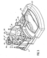
- la figure 1 représente une vue en coupe partielle longitudinale d'une machine à café selon l'invention;
- la figure 2 est une vue en perspective de la partie arrière de la machine avec le réservoir d'eau retiré de son siège et représenté à côté;
- la figure 3 représente une vue en perspective de la partie inférieure du socle de la machine, une partie des pièces constituant l'enveloppe extérieure de la machine étant enlevée pour faciliter la visualisation;
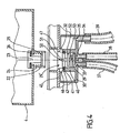
- la figure 4 est une vue en coupe axiale de la partie de connexion du réservoir avec la partie correspondante du socle de la machine.
- Figure 1 shows a longitudinal sectional view of a coffee machine according to the invention;
- Figure 2 is a perspective view of the rear portion of the machine with the water tank removed from its seat and shown beside;
- Figure 3 shows a perspective view of the lower part of the base of the machine, a part of the parts constituting the outer casing of the machine being removed for easy viewing;
- Figure 4 is an axial sectional view of the connection portion of the tank with the corresponding portion of the base of the machine.
La figure 1 illustre une machine à café selon l'invention comportant un corps 1 dont la partie inférieure comprend un socle 2 qui est relié à la partie supérieure du corps 1 par un montant vertical 3 servant d'appui à un réservoir 4 d'eau froide. Le corps 1 renferme le circuit hydraulique de la machine comportant le réservoir 4, une pompe 5, un thermobloc 6, un distributeur 7 et un vérin 8 de compression de la mouture de café.FIG. 1 illustrates a coffee machine according to the invention comprising a
La mouture de café est placée dans une coupelle munie d'une paroi filtrante appelée porte-filtre 9 qui est, dans l'exemple décrit, monté coulissant selon une direction horizontale dans les rainures d'un support fixe de la tête d'infusion 10.The ground coffee is placed in a cup provided with a filtering wall called
Le vérin 8 comporte un nez monté coulissant verticalement par rapport au corps 1 de la machine adapté à pénétrer, au cours de chaque cycle de fonctionnement, à l'intérieur du porte-filtre 9 afin de comprimer la mouture. L'eau fournie par la pompe 5 actionne le vérin hydraulique 8 qui pousse le nez contre la mouture. A partir d'une valeur prédéfinie de la pression, un clapet situé à l'intérieur dudit nez permet le passage de l'eau du thermobloc 6 vers le porte-filtre 9 d'où l'infusion s'écoule dans un récipient collecteur situé sur un support 11 du socle 2.The
La machine a café comporte une chaudière ou thermobloc 6 destiné à chauffer l'eau sous pression fournie par la pompe 5 avant de l'injecter dans la mouture de café du porte-filtre 9. Le thermobloc 6 comprend des canaux échangeurs de chaleur 17 permettant la circulation de l'eau à l'intérieur du thermobloc 6 qui comprend par ailleurs un élément chauffant électrique 12 et un capteur de température 13. L'eau en provenance de la pompe 5 arrive par un canal d'entrée 14 du thermobloc 6 et peut ressortir suivant deux chemins de ce dernier, selon la position du distributeur 7. Soit l'eau sort froide par un canal de sortie 15, qui forme avec le canal d'entrée 14 un circuit très court ne permettant pas à l'eau de se réchauffer dans le thermobloc, soit l'eau sort chaude par un canal de sortie 16 après avoir circulé dans les canaux échangeurs de chaleur 17 du thermobloc 6.The coffee machine comprises a boiler or
En fin d'extraction du café boisson, le distributeur 7 est ramené en position de repos par l'utilisateur, ce qui fait que l'eau chaude sous pression du circuit hydraulique est envoyée par une canalisation de détente vers le réservoir 4.At the end of extraction of the coffee drink, the
Le réservoir 4 est monté de manière amovible sur la machine de l'invention et il comporte, tel que visible à la figure 2, des crochets 20 qui peuvent s'engager dans des oeillets 21 prévus à cet effet dans la paroi frontale en vis à vis du montant vertical 3. Le réservoir 4 a une forme généralement parallélépipédique ouvert en sa partie supérieure pour faciliter son remplissage et fermé en sa partie inférieure par un clapet 23 (figure 4) situé à l'intérieur d'une colonne 22. Le clapet 23 est normalement fermé sous l'action d'un ressort de rappel 24 qui maintient sa partie supérieure 23 appuyée contre le fond du réservoir 4 par interposition d'une rondelle d'étanchéité 26. Lorsque le réservoir 4 est mis en place, la colonne 22 repose dans un alésage 29 du socle 2, des moyens étant prévus dans le socle pour ouvrir le clapet 23 et mettre en communication le liquide du réservoir 4 avec les conduites du circuit hydraulique de la machine.The
Tel que mieux visible aux figures 3 et 4, l'alésage 29 est pratiqué dans une pièce de forme concave appelée entonnoir 30 supportée par des plots de fixation 31 au socle 2 de la machine. La base de l'entonnoir 30 présente plusieurs orifices de communication avec les conduites du circuit hydraulique de la machine. Ainsi, deux orifices 33 et 34, sont pratiqués au fond de l'alésage 29, de part et d'autre de l'axe de ce dernier, et communiquent l'un avec une conduite de détente 37 et l'autre avec une conduite du circuit principal 38. Un orifice périphérique 35 est prévu pour mettre en communication l'entonnoir 30 avec une conduite d'évacuation 39.As best seen in Figures 3 and 4, the
Par conduite du circuit principal 38 on comprend une conduite qui relie l'entonnoir 30, respectivement le réservoir 4, à la pompe 5, alors que par conduite de détente 37 on comprend une conduite qui relie le conduit de sortie du thermobloc 6 à l'entonnoir 30. La conduite d'évacuation 39 relie quant à elle l'entonnoir 30 à un bac de récupération, tel qu'il sera expliqué par la suite.By conduit of the
Les conduites 37, 38 et 39 sont des tuyaux flexibles, réalisés par exemple en caoutchouc, qui sont raccordés sur des embouts creux verticaux matérialisant lesdits orifices 33, 34 et 35, tel que visible à la figure 4. De la même manière, l'extrémité opposée de chaque conduite est mise en communication par des éléments de raccordement du même type avec son élément de circuit hydraulique respectif.The
L'alésage 29 est défini par le diamètre intérieur d'une paroi cylindrique 40 formée approximativement au centre de l'entonnoir 30. Tel que mieux visible à la figure 3, l'entonnoir 30 a une forme oblongue présentant, le long de son axe principal, une paroi frontale 42 recourbée et une paroi opposée 42' plane.The
L'entonnoir 30 étant une pièce de forme assez complexe, elle peut avantageusement être réalisée en une matière plastique par une technique d'injection.The
La surface supérieure de la paroi cylindrique 40 (figure 4) comporte une rainure 41 dans laquelle est placé un joint torique 43. Le joint torique 43 prend appui sur la surface extérieure de la colonne 22 du réservoir 4 lors de sa mise en place sur la machine à café, ce joint ayant le rôle d'assurer l'étanchéité entre le réservoir 4 et l'alésage 29 de la paroi cylindrique 40 de l'entonnoir 30, respectivement entre le réservoir 4 et le reste du circuit hydraulique de la machine. Le joint torique 43 est maintenu en place par les crénelures 46 d'une platine 45.The upper surface of the cylindrical wall 40 (Figure 4) has a
La platine 45 est positionnée au-dessus de l'entonnoir 30 de manière à le fermer au moins partiellement, cette platine 45 étant fixée à son tour par des plots de fixation prévus à cet effet dans le socle 2. La platine 45 présente dans sa partie centrale un orifice 29' traversant situé dans le prolongement de l'alésage 29 de la paroi cylindrique 40 de l'entonnoir 30 et ayant un diamètre légèrement supérieur au diamètre de ce dernier.The
La surface interne de la platine 45, qui fait face à l'entonnoir 30, présente une couronne munie de crénelures 46 bordant l'orifice 29'. La partie pleine de ces crénelures 46 a le rôle de maintenir en place le joint torique 43, alors que les découpages situés entre deux crénelures 46 forment des passages 32 ayant le rôle de mettre en communication l'intérieur de l'alésage 29 avec son pourtour, donc avec la partie périphérique de l'entonnoir 30.The inner surface of the
Sur la partie externe de la platine 45, faisant face au réservoir 4, sont réalisées deux nervures de guidage 47 parallèles entre elles, disposées de part et d'autre de l'orifice 29' en étant perpendiculaires aux parois frontales 42, 42'. La platine 45 présente, en bordure des nervures 47, une ouverture 48 qui permet à nouveau, mais à un niveau supérieur, la communication avec la partie périphérique de l'entonnoir 30. Par niveau supérieur on comprend un niveau situé en aval par rapport aux crénelures 46 dans le sens d'écoulement du flux de retour de l'eau chaude vers le réservoir en fin de cycle.On the outer part of the
Par ailleurs et tel que représenté en figure 4, au fond de l'alésage 29 est fixé un ensemble brise jet 50 vertical d'axe longitudinal coaxial à celui de l'alésage 29 et, respectivement à celui de la colonne 22 du réservoir 4. L'ensemble brise jet comporte en sa partie supérieure un déflecteur 51 proéminent qui prend appui sur la partie inférieure 25 du clapet 23 afin de provoquer son ouverture lors de la mise en place du réservoir 4. La partie inférieure de l'ensemble brise jet 50 comporte plusieurs ailettes 52 agencées de manière décentrée en alternance, l'une au dessus de l'autre, le long de l'axe longitudinal de l'ensemble brise jet 50.Furthermore and as shown in FIG. 4, at the bottom of the
Tel que visible à la figure 4, deux ailettes adjacentes touchent avec une partie de leur périphérie les deux extrémités opposées de la surface intérieure de l'alésage 29, un cheminement en zigzag étant ainsi formé entre leurs extrémités libres, ce cheminement débouchant dans l'orifice 33 communiquant avec la conduite de détente 37. Les ailettes 52 peuvent avoir une forme de disque ou toute autre forme plane ou gauche adaptée au but recherché. Un tel agencement oblige le jet d'eau arrivant par le fond de l'alésage 29 à avoir un parcours sinueux, en sillonnant les chicanes formées par les extrémités décalées des ailettes 52, ce qui a pour effet la perte de charge ou la diminution de la pression du jet d'eau de retour vers le réservoir.As seen in Figure 4, two adjacent fins touch with part of their periphery the two opposite ends of the inner surface of the
En référence à la figure 3, on remarque que la conduite d'évacuation 39 part du fond de l'entonnoir 30 et conduit le liquide collecté par ce dernier vers un récupérateur 55 situé en dessous d'un embout récupérateur 54 et communiquant avec ce dernier, embout sur lequel vient se raccorder la conduite d'évacuation 39. L'entonnoir 30 étant surélevé par rapport au récupérateur 55, le liquide collecté par l'entonnoir 30 s'écoule rapidement vers le récupérateur 55.Referring to Figure 3, it is noted that the
Le récupérateur 55 fait corps commun avec un bac de récupération 56 dont il constitue un prolongement en gouttière. Le bac de récupération 56 est avantageusement monté amovible par rapport au corps 1 de la machine et pour ceci il présente une forme rentrante sous le socle 2. Le bac de récupération 56 présente par ailleurs un rebord 57 sur lequel est installé le support 11 de tasse à café, support qui est sous forme d'une grille permettant de récolter dans le même bac 56 les éventuels écoulements résultant de l'infusion du café.The
En fonctionnement, lorsque la cafetière arrive en fin de cycle d'extraction du café, l'utilisateur ramène le distributeur 7 en position de repos ce qui fait que le flux d'eau chaude sous pression qui se trouve encore dans le circuit hydraulique en sortie du thermobloc 6, est envoyé par une canalisation de détente 37 vers le réservoir 4. Dans son chemin, ce flux d'eau chaude turbulent est cassé par les ailettes 52 de l'ensemble brise jet 50 et il est canalisé vers une zone prévue à cet effet. Cette zone peut être le réservoir 4 lorsque ce dernier est bien mis en place afin qu'il communique de manière étanche avec l'alésage 29 de l'entonnoir 30.In operation, when the coffee maker arrives at the end of the coffee extraction cycle, the user returns the
Par contre, si au cours du retour du flux d'eau chaude vers le réservoir 4, l'utilisateur enlève de manière intempestive le réservoir 4, où également s'il le soulève légèrement de manière à ce que son clapet 23 poussé par le ressort de rappel 24 ferme la communication du réservoir 4 avec l'entonnoir 30, le flux de retour sera canalisé par le dispositif de l'invention vers la zone périphérique de l'entonnoir 30. Cette canalisation se fait à travers les découpages situés entre les crénelures 46 de la platine 45 pour un jet peu turbulent calmé par les ailettes 52 du brise jet 50. Au cas où le flux de retour ou de détente n'est pas suffisamment freiné par l'ensemble brise jet 50, il arrive sur la face supérieure de la platine 45 et les débordements sont canalisés à nouveau par les nervures de canalisation 47 de la platine 45 vers l'ouverture 48 et d'ici dans l'entonnoir 30. De l'entonnoir 30, les débordements arrivent par la conduite d'évacuation 39 dans le bac de récupération 56 où ils sont stockés avant de vider le bac.On the other hand, if during the return of the flow of hot water to the
D'autres variantes de réalisation de l'invention peuvent être envisagées sans sortir du cadre de ses revendications.Other embodiments of the invention can be envisaged without out of the scope of his claims.
Ainsi, on peut imaginer que le joint torique 43 est tenu par une rainure pratiquée dans la paroi interne de l'alésage 29, le passage entre l'alésage 29 et l'entonnoir 30 en l'absence du réservoir 4 pouvant se faire par un espace ménagé entre le bord supérieur de l'alésage 29 et la face interne de la platine 45.Thus, one can imagine that the O-
Dans une autre variante on peut imaginer que le joint torique 43 est tenu par la paroi de la colonne 22 du réservoir 4. On peut également envisager une étanchéité frontale entre la base de la colonne 22 du réservoir 4 et une surface correspondante du dispositif de connexion 28.In another variant it is possible to imagine that the O-
Dans encore une autre variante, on peut envisager l'utilisation d'autres moyens de détente, notamment sous forme d'ailettes souples issues d'une paroi périphérique installée dans la conduite de détente ou d'ailettes installées dans l'orifice de communication avec la conduite de détente du dispositif de connexion du réservoir.In yet another variant, it is possible to envisage the use of other expansion means, in particular in the form of flexible fins coming from a peripheral wall installed in the expansion pipe or fins installed in the communication orifice with the detent pipe of the tank connection device.
Claims (14)
- An espresso type coffeemaker presenting a removable tank (4) connected to a main water circuit including a pump (5) that sucks water from the tank (4) and delivers it to a heater block (6), and from the heater block through coffee grounds contained in a filter carrier (9), said tank (4) also being connected to a water circuit for returning water leaving the heater block, the coffeemaker being characterized in that the device (28) connecting said tank (4) with said water circuits includes means (49) for reducing the pressure of the jet of water arriving via the water circuit returning to the tank, and means (44) for directing said jet towards a storage zone.
- A coffeemaker according to claim 1, characterized in that the means (49) for reducing pressure direct the water jet in a direction other than that of the main axis of the device (28) connecting said tank (4) with the water circuits of the coffeemaker.
- A coffeemaker according to claim 1 or claim 2, characterized in that the connection device (28) includes a central bore (29) putting it into communication at one end with said tank (4), the other end of the bore opening out into two orifices (33, 34) one (34) communicating with the main water circuit and the other (33) communicating with the return water circuit, wherein said means (49) for reducing the pressure of the water jet are arranged in line with the axis of the orifice (33) that communicates with said water return circuit.
- A coffeemaker according to any preceding claim, characterized in that said means (49) for reducing pressure comprise a plurality of parallel fins (52) arranged in alternation about a common axis (53).
- A coffeemaker according to claim 4, characterized in that said common axis (53) includes a deflector (51) situated on the axis of the valve member for closing the tank (4) when the tank is connected to the connection device (28).
- A coffeemaker according to any preceding claim, characterized in that said means (44) for directing the jet of water are disposed downstream from said means (49) for reducing the pressure of the jet of water, downstream being in the flow direction of said jet of water.
- A coffeemaker according to claim 6, characterized in that said means (44) for directing the water jet include at least one passage putting the inside of the bore (29) of the connection device (28) into communication with a funnel (30) surrounding said bore (29).
- A coffeemaker according to claim 7, characterized in that said means (44) for directing the jet include a first passage (32) situated downstream from an O-ring (43) providing sealing between the tank (4) and the bore (29) of the connection device (28) as seen in the flow direction of the return water jet towards the tank (4).
- A coffeemaker according to claim 8, characterized in that said first passage (32) is made between the top portion of the bore (29) and the inside face of a plate (45) placed on the funnel (30).
- A coffeemaker according to claim 9, characterized in that means (44) for directing the water jet include a second passage in the form of an opening (48) formed in the plate (45), which opening (48) is situated downstream from the first passage (32) as seen in the flow direction of the return jet of water towards the tank (4).
- A coffeemaker according to claim 10, characterized in that said means (44) for directing the water jet comprise channeling ribs (47) situated on either side of an orifice in the plate (45) communicating with the bore (29) of the connection device (28), said ribs extending to the proximity of the opening (48).
- A coffeemaker according to any one of claims 7 to 11, characterized in that said means (44) for directing the water jet communicate via an exhaust opening (35) of the funnel (30) with a recovery vessel (56) removably mounted in the coffeemaker.
- A coffeemaker according to claim 12, characterized in that said recovery vessel (56) includes a trough-shaped extension forming recovery means (55) coming under a recovery endpiece (54) that is connected to a duct (39) for emptying the funnel (30).
- A coffeemaker according to claim 12, characterized in that said recovery vessel (56) maintains a support for an infusion-collector receptacle.
Applications Claiming Priority (3)
| Application Number | Priority Date | Filing Date | Title |
|---|---|---|---|
| FR0207557 | 2002-06-19 | ||
| FR0207557A FR2841116B1 (en) | 2002-06-19 | 2002-06-19 | EXPRESSO TYPE COFFEE MAKER WITH REMOVABLE WATER TANK |
| PCT/FR2003/001593 WO2004000083A1 (en) | 2002-06-19 | 2003-05-27 | Espresso coffeemaker with removable water reservoir |
Publications (2)
| Publication Number | Publication Date |
|---|---|
| EP1513434A1 EP1513434A1 (en) | 2005-03-16 |
| EP1513434B1 true EP1513434B1 (en) | 2007-09-26 |
Family
ID=29719869
Family Applications (1)
| Application Number | Title | Priority Date | Filing Date |
|---|---|---|---|
| EP03760718A Expired - Lifetime EP1513434B1 (en) | 2002-06-19 | 2003-05-27 | Espresso coffeemaker with removable water reservoir |
Country Status (9)
| Country | Link |
|---|---|
| US (1) | US7347137B2 (en) |
| EP (1) | EP1513434B1 (en) |
| AT (1) | ATE373982T1 (en) |
| AU (1) | AU2003249422A1 (en) |
| DE (1) | DE60316560T2 (en) |
| ES (1) | ES2291683T3 (en) |
| FR (1) | FR2841116B1 (en) |
| PT (1) | PT1513434E (en) |
| WO (1) | WO2004000083A1 (en) |
Families Citing this family (31)
| Publication number | Priority date | Publication date | Assignee | Title |
|---|---|---|---|---|
| KR100628138B1 (en) * | 2003-12-02 | 2006-09-26 | 엘지전자 주식회사 | microwave oven having coffee maker |
| DE102004004837B4 (en) * | 2004-01-30 | 2013-11-21 | BSH Bosch und Siemens Hausgeräte GmbH | coffee machine |
| DE102004004822A1 (en) * | 2004-01-30 | 2005-08-18 | BSH Bosch und Siemens Hausgeräte GmbH | Coffee machine and water tank for a coffee machine |
| CN100451454C (en) * | 2004-09-21 | 2009-01-14 | 乐金电子(天津)电器有限公司 | Microwave oven with coffee apparatus |
| EP1828411B1 (en) * | 2004-12-03 | 2012-11-07 | Human Genetic Signatures PTY Ltd | Methods for simplifying microbial nucleic acids by chemical modification of cytosines |
| AU2007235900A1 (en) | 2006-04-07 | 2007-10-18 | Novartis Ag | Combination comprising a) a pyrimidylaminobenzamide compound, and b) a Thr315lle kinase inhibitor |
| US7640846B2 (en) * | 2006-06-26 | 2010-01-05 | Hamilton Beach Brands, Inc. | Diverter valve and channel for brewed beverage maker |
| JP2009545592A (en) | 2006-07-31 | 2009-12-24 | プリーシス・ファーマシューティカルズ・インコーポレイテッド | Aurora kinase inhibitors from encoded small molecule libraries |
| JP2009545598A (en) | 2006-08-01 | 2009-12-24 | プリーシス・ファーマシューティカルズ・インコーポレイテッド | P38 kinase inhibitor |
| PL2317898T3 (en) | 2008-07-14 | 2013-02-28 | Nestec Sa | Water circulation system for a beverage preparation device |
| US20110005398A1 (en) * | 2009-07-09 | 2011-01-13 | Wal-Mart Stores, Inc. | Method and System to Produce Gourmet Coffee |
| NL2003409C2 (en) * | 2009-08-28 | 2011-03-01 | Dijk 3D Engineering B V Van | DEVICE AND METHOD FOR COUPLING A WATER RESERVOIR TO A COFFEE MAKER. |
| ATE522169T2 (en) * | 2009-10-23 | 2011-09-15 | Gruppo Cimbali Spa | COFFEE MACHINE WITH DISPENSING PRESSURE REGULATION AND ASSOCIATED METHOD |
| PT2314183E (en) * | 2009-10-23 | 2011-11-08 | Gruppo Cimbali Spa | A coffee machine with dispensing pressure regulation and a method relating thereto |
| DE102009055074B4 (en) * | 2009-12-21 | 2020-01-09 | BSH Hausgeräte GmbH | household appliance |
| US20110174168A1 (en) * | 2010-01-21 | 2011-07-21 | AMF Automation Technologies, LLC d/b/a AMF Bakery Systems | Dough Pump and Developer |
| WO2011089210A1 (en) * | 2010-01-21 | 2011-07-28 | Nestec S.A. | Beverage machine with removable liquid supply reservoir |
| JP5617029B2 (en) * | 2010-04-15 | 2014-10-29 | アルフレッド ケルヒャー ゲーエムベーハー ウント コンパニー カーゲー | Steam cleaner |
| FR2960403B1 (en) * | 2010-05-25 | 2013-01-18 | Cie Mediterraneenne Des Cafes | ASSEMBLY FOR INFUSION BEVERAGE PRODUCTION MACHINE |
| PL2603123T3 (en) * | 2010-08-13 | 2019-03-29 | Koninklijke Philips N.V. | A water container and a machine for making beverages comprising said container |
| US10383474B2 (en) * | 2011-05-10 | 2019-08-20 | Breville Pty Limited | Coffee machine with overflow feature |
| DE102011081839A1 (en) * | 2011-08-30 | 2013-02-28 | BSH Bosch und Siemens Hausgeräte GmbH | Water tank for a household appliance |
| CH706027A2 (en) | 2012-01-23 | 2013-07-31 | Francisco Speich | Machine for beverage preparation, without respect of tap water. |
| EP2868398A1 (en) | 2013-10-29 | 2015-05-06 | Cliris SA | Device and Method for Ultrasonic Cleaning |
| WO2015063171A2 (en) | 2013-10-29 | 2015-05-07 | Cliris Sa | Cleaning device, methods of cleaning and recipients with cleaning liquid |
| CN203619242U (en) * | 2013-11-11 | 2014-06-04 | 李文钦 | Multifunctional water cup of water dispenser |
| EP2896332B1 (en) * | 2014-01-15 | 2016-08-17 | De'Longhi Appliances S.r.l. | Device associable with a steam dispensing nozzle of a coffee machine for the production of a milk-based beverage |
| US10687655B2 (en) | 2014-02-25 | 2020-06-23 | Newco Enterprises, Inc. | Beverage brewing device for brewing and removal of different sized beverage capsules |
| US9788682B2 (en) | 2014-02-25 | 2017-10-17 | Newco Enterprises, Inc. | Beverage brewing device for automatically brewing and dispensing single cup quantities of beverage through a vending machine with minimal manual participation |
| US11272804B2 (en) | 2014-02-25 | 2022-03-15 | Newco Enterprises, Inc. | Beverage brewing device for brewing and removal of different sized flavored beverage packets (POD) |
| CA3001089A1 (en) * | 2015-11-11 | 2017-05-18 | Nestec S.A. | Easy connection of a liquid tank to a beverage machine |
Family Cites Families (18)
| Publication number | Priority date | Publication date | Assignee | Title |
|---|---|---|---|---|
| US2715868A (en) * | 1951-11-23 | 1955-08-23 | Internat Coffee Corp | Coffee extracting and dispensing apparatus |
| US3085495A (en) * | 1954-08-26 | 1963-04-16 | Rosander Axel Edward | Automatic pressurized coffee maker |
| US2935011A (en) * | 1958-06-10 | 1960-05-03 | Perlman Yaakov | Beverage-making machine |
| CH377504A (en) * | 1960-04-12 | 1964-05-15 | Omre S A S | Machine for preparing coffee infusion |
| US3278087A (en) * | 1964-07-01 | 1966-10-11 | Stasse Roland | Hot-drink dispensing machine |
| US3423209A (en) * | 1965-11-23 | 1969-01-21 | Robert L Weber | Brewing selectable variable quantities of coffee |
| US3927802A (en) * | 1974-03-05 | 1975-12-23 | Jet Spray Cooler Inc | Manual fill hot beverage dispenser |
| US3915341A (en) * | 1974-11-27 | 1975-10-28 | Jet Spray Cooler Inc | Manual fill hot beverage dispenser |
| CH587647A5 (en) | 1975-07-11 | 1977-05-13 | Icomag Trust Reg | |
| IT7821703V0 (en) * | 1978-05-03 | 1978-05-03 | Illy Caffe S P A | MACHINE FOR MAKING A CUP OF COFFEE. |
| IT8321614V0 (en) | 1983-04-21 | 1983-04-21 | Cavalli Alfredo | ESPRESSO COFFEE MACHINE FOR DOMESTIC USE EQUIPPED WITH INSUFFICIENT WATER LEVEL INDICATOR IN THE TANK. |
| US5372061A (en) * | 1993-04-14 | 1994-12-13 | Avanti Espresso U.S.A., Inc. | Espresso/cappuccino apparatus and method |
| US5566605A (en) * | 1993-11-09 | 1996-10-22 | Seb S.A. | Centrifugal type extraction cell having a deformable sealing joint for a hot beverage preparation machine |
| DE4436080A1 (en) * | 1994-10-10 | 1996-04-11 | Braun Ag | Brewing device for a household espresso machine |
| EP0915673A1 (en) * | 1996-12-23 | 1999-05-19 | Koninklijke Philips Electronics N.V. | Coffee maker |
| FR2806606B1 (en) * | 2000-03-24 | 2002-10-25 | Moulinex Sa | ELECTRIC COFFEE MACHINE WITH PIVOTING WATER TANK |
| FR2807930B1 (en) * | 2000-04-21 | 2002-06-14 | Seb Sa | EXPRESSO COFFEE MAKER WITH TWO THERMOSTATS |
| EP1322896B1 (en) * | 2000-10-02 | 2010-04-14 | Koninklijke Philips Electronics N.V. | Water flow heater |
-
2002
- 2002-06-19 FR FR0207557A patent/FR2841116B1/en not_active Expired - Fee Related
-
2003
- 2003-05-27 PT PT03760718T patent/PT1513434E/en unknown
- 2003-05-27 ES ES03760718T patent/ES2291683T3/en not_active Expired - Lifetime
- 2003-05-27 AT AT03760718T patent/ATE373982T1/en not_active IP Right Cessation
- 2003-05-27 DE DE60316560T patent/DE60316560T2/en not_active Expired - Lifetime
- 2003-05-27 AU AU2003249422A patent/AU2003249422A1/en not_active Abandoned
- 2003-05-27 WO PCT/FR2003/001593 patent/WO2004000083A1/en active IP Right Grant
- 2003-05-27 EP EP03760718A patent/EP1513434B1/en not_active Expired - Lifetime
- 2003-05-27 US US10/518,354 patent/US7347137B2/en not_active Expired - Fee Related
Also Published As
| Publication number | Publication date |
|---|---|
| DE60316560T2 (en) | 2008-06-26 |
| US7347137B2 (en) | 2008-03-25 |
| WO2004000083A1 (en) | 2003-12-31 |
| FR2841116B1 (en) | 2004-11-26 |
| DE60316560D1 (en) | 2007-11-08 |
| AU2003249422A1 (en) | 2004-01-06 |
| US20050247204A1 (en) | 2005-11-10 |
| ATE373982T1 (en) | 2007-10-15 |
| EP1513434A1 (en) | 2005-03-16 |
| FR2841116A1 (en) | 2003-12-26 |
| ES2291683T3 (en) | 2008-03-01 |
| PT1513434E (en) | 2008-01-11 |
Similar Documents
| Publication | Publication Date | Title |
|---|---|---|
| EP1513434B1 (en) | Espresso coffeemaker with removable water reservoir | |
| EP1009270B1 (en) | Brewing unit for automatic beverage dispensers comprising in particular a boiler | |
| CA2931404C (en) | Electrical appliance for the steam-heating and/or -cooking of food | |
| EP3580385B1 (en) | Iron including a device for retaining scale particles transported by the steam | |
| FR2721381A1 (en) | Device for producing hot water or steam. | |
| FR2929961A1 (en) | HOUSEHOLD APPLIANCE COMPRISING A BASE FOR THE PRODUCTION OF STEAM COMPRISING A REMOVABLE TANK | |
| EP0743037B1 (en) | Domestic coffee machine | |
| FR2855734A1 (en) | FILTER COFFEE MAKER WITH HOT WATER DISTRIBUTION IN THE COVER. | |
| EP2506743B1 (en) | Appliance for preparing infused beverages having a removable store | |
| EP1798325B1 (en) | Laundry dryer with liquid reservoir | |
| FR3091813A1 (en) | BEVERAGE PREPARATION MACHINE EQUIPPED WITH A PERFECTED CONTAINER FOR USED CAPSULES | |
| EP0616786B1 (en) | Coffee brewer with water return conduct | |
| EP1259145B1 (en) | Filter-holder for espresso-coffee maker | |
| EP0449792B1 (en) | Improved filter holder for a percolator | |
| FR3072104B1 (en) | HOUSEHOLD APPLIANCE COMPRISING A BASE COMPRISING A BOILING CHAMBER POWERED BY GRAVITY | |
| EP3757279B1 (en) | Iron comprising a device for retaining scale particles carried by steam | |
| EP4302658A1 (en) | Method for optimized cleaning of an infusion chamber of a coffee machine | |
| FR2577405A1 (en) | Device for infusion of coffee under pressure | |
| EP3735872B1 (en) | Machine for preparing a beverage provided with a water tank and a pressure sensor for measuring an amount of water extracted from said tank | |
| EP2378930B1 (en) | Infusion filtering device and appliance for brewing infusions fitted with such a device | |
| FR3047160A1 (en) | COFFEE FILTER PROVIDED WITH AN ANTI-DROP DEVICE | |
| WO2006030292A1 (en) | Small-sized bottled water station | |
| FR2803737A1 (en) | EXPRESSO COFFEE MAKER EQUIPPED WITH A THERMAL BLOCK PURGE SYSTEM | |
| EP4299825A1 (en) | Household ironing and/or smoothing appliance comprising a device for retaining scale particles carried by steam | |
| EP1483990B1 (en) | Filtercoffeemachine with gasket between lid and housing |
Legal Events
| Date | Code | Title | Description |
|---|---|---|---|
| PUAI | Public reference made under article 153(3) epc to a published international application that has entered the european phase |
Free format text: ORIGINAL CODE: 0009012 |
|
| 17P | Request for examination filed |
Effective date: 20041126 |
|
| AK | Designated contracting states |
Kind code of ref document: A1 Designated state(s): AT BE BG CH CY CZ DE DK EE ES FI FR GB GR HU IE IT LI LU MC NL PT RO SE SI SK TR |
|
| AX | Request for extension of the european patent |
Extension state: AL LT LV MK |
|
| DAX | Request for extension of the european patent (deleted) | ||
| GRAP | Despatch of communication of intention to grant a patent |
Free format text: ORIGINAL CODE: EPIDOSNIGR1 |
|
| GRAS | Grant fee paid |
Free format text: ORIGINAL CODE: EPIDOSNIGR3 |
|
| GRAA | (expected) grant |
Free format text: ORIGINAL CODE: 0009210 |
|
| AK | Designated contracting states |
Kind code of ref document: B1 Designated state(s): AT BE BG CH CY CZ DE DK EE ES FI FR GB GR HU IE IT LI LU MC NL PT RO SE SI SK TR |
|
| REG | Reference to a national code |
Ref country code: GB Ref legal event code: FG4D Free format text: NOT ENGLISH |
|
| REG | Reference to a national code |
Ref country code: CH Ref legal event code: EP |
|
| REF | Corresponds to: |
Ref document number: 60316560 Country of ref document: DE Date of ref document: 20071108 Kind code of ref document: P |
|
| REG | Reference to a national code |
Ref country code: IE Ref legal event code: FG4D Free format text: LANGUAGE OF EP DOCUMENT: FRENCH |
|
| REG | Reference to a national code |
Ref country code: CH Ref legal event code: NV Representative=s name: MOINAS & SAVOYE SA |
|
| REG | Reference to a national code |
Ref country code: PT Ref legal event code: SC4A Free format text: AVAILABILITY OF NATIONAL TRANSLATION Effective date: 20071220 |
|
| PG25 | Lapsed in a contracting state [announced via postgrant information from national office to epo] |
Ref country code: FI Free format text: LAPSE BECAUSE OF FAILURE TO SUBMIT A TRANSLATION OF THE DESCRIPTION OR TO PAY THE FEE WITHIN THE PRESCRIBED TIME-LIMIT Effective date: 20070926 |
|
| PG25 | Lapsed in a contracting state [announced via postgrant information from national office to epo] |
Ref country code: AT Free format text: LAPSE BECAUSE OF FAILURE TO SUBMIT A TRANSLATION OF THE DESCRIPTION OR TO PAY THE FEE WITHIN THE PRESCRIBED TIME-LIMIT Effective date: 20070926 |
|
| REG | Reference to a national code |
Ref country code: ES Ref legal event code: FG2A Ref document number: 2291683 Country of ref document: ES Kind code of ref document: T3 |
|
| GBV | Gb: ep patent (uk) treated as always having been void in accordance with gb section 77(7)/1977 [no translation filed] | ||
| PG25 | Lapsed in a contracting state [announced via postgrant information from national office to epo] |
Ref country code: GR Free format text: LAPSE BECAUSE OF FAILURE TO SUBMIT A TRANSLATION OF THE DESCRIPTION OR TO PAY THE FEE WITHIN THE PRESCRIBED TIME-LIMIT Effective date: 20071227 |
|
| REG | Reference to a national code |
Ref country code: IE Ref legal event code: FD4D |
|
| PG25 | Lapsed in a contracting state [announced via postgrant information from national office to epo] |
Ref country code: SK Free format text: LAPSE BECAUSE OF FAILURE TO SUBMIT A TRANSLATION OF THE DESCRIPTION OR TO PAY THE FEE WITHIN THE PRESCRIBED TIME-LIMIT Effective date: 20070926 Ref country code: CZ Free format text: LAPSE BECAUSE OF FAILURE TO SUBMIT A TRANSLATION OF THE DESCRIPTION OR TO PAY THE FEE WITHIN THE PRESCRIBED TIME-LIMIT Effective date: 20070926 |
|
| PG25 | Lapsed in a contracting state [announced via postgrant information from national office to epo] |
Ref country code: RO Free format text: LAPSE BECAUSE OF FAILURE TO SUBMIT A TRANSLATION OF THE DESCRIPTION OR TO PAY THE FEE WITHIN THE PRESCRIBED TIME-LIMIT Effective date: 20070926 Ref country code: SE Free format text: LAPSE BECAUSE OF FAILURE TO SUBMIT A TRANSLATION OF THE DESCRIPTION OR TO PAY THE FEE WITHIN THE PRESCRIBED TIME-LIMIT Effective date: 20071226 |
|
| PG25 | Lapsed in a contracting state [announced via postgrant information from national office to epo] |
Ref country code: DK Free format text: LAPSE BECAUSE OF FAILURE TO SUBMIT A TRANSLATION OF THE DESCRIPTION OR TO PAY THE FEE WITHIN THE PRESCRIBED TIME-LIMIT Effective date: 20070926 |
|
| PLBE | No opposition filed within time limit |
Free format text: ORIGINAL CODE: 0009261 |
|
| STAA | Information on the status of an ep patent application or granted ep patent |
Free format text: STATUS: NO OPPOSITION FILED WITHIN TIME LIMIT |
|
| 26N | No opposition filed |
Effective date: 20080627 |
|
| PG25 | Lapsed in a contracting state [announced via postgrant information from national office to epo] |
Ref country code: IE Free format text: LAPSE BECAUSE OF FAILURE TO SUBMIT A TRANSLATION OF THE DESCRIPTION OR TO PAY THE FEE WITHIN THE PRESCRIBED TIME-LIMIT Effective date: 20070926 |
|
| PG25 | Lapsed in a contracting state [announced via postgrant information from national office to epo] |
Ref country code: GB Free format text: LAPSE BECAUSE OF FAILURE TO SUBMIT A TRANSLATION OF THE DESCRIPTION OR TO PAY THE FEE WITHIN THE PRESCRIBED TIME-LIMIT Effective date: 20070926 |
|
| BERE | Be: lapsed |
Owner name: SEB S.A. Effective date: 20080531 |
|
| PG25 | Lapsed in a contracting state [announced via postgrant information from national office to epo] |
Ref country code: MC Free format text: LAPSE BECAUSE OF NON-PAYMENT OF DUE FEES Effective date: 20080531 |
|
| PG25 | Lapsed in a contracting state [announced via postgrant information from national office to epo] |
Ref country code: BE Free format text: LAPSE BECAUSE OF NON-PAYMENT OF DUE FEES Effective date: 20080531 |
|
| PG25 | Lapsed in a contracting state [announced via postgrant information from national office to epo] |
Ref country code: EE Free format text: LAPSE BECAUSE OF FAILURE TO SUBMIT A TRANSLATION OF THE DESCRIPTION OR TO PAY THE FEE WITHIN THE PRESCRIBED TIME-LIMIT Effective date: 20070926 |
|
| PG25 | Lapsed in a contracting state [announced via postgrant information from national office to epo] |
Ref country code: SI Free format text: LAPSE BECAUSE OF FAILURE TO SUBMIT A TRANSLATION OF THE DESCRIPTION OR TO PAY THE FEE WITHIN THE PRESCRIBED TIME-LIMIT Effective date: 20070926 |
|
| PG25 | Lapsed in a contracting state [announced via postgrant information from national office to epo] |
Ref country code: CY Free format text: LAPSE BECAUSE OF FAILURE TO SUBMIT A TRANSLATION OF THE DESCRIPTION OR TO PAY THE FEE WITHIN THE PRESCRIBED TIME-LIMIT Effective date: 20070926 |
|
| PG25 | Lapsed in a contracting state [announced via postgrant information from national office to epo] |
Ref country code: BG Free format text: LAPSE BECAUSE OF FAILURE TO SUBMIT A TRANSLATION OF THE DESCRIPTION OR TO PAY THE FEE WITHIN THE PRESCRIBED TIME-LIMIT Effective date: 20071226 |
|
| PG25 | Lapsed in a contracting state [announced via postgrant information from national office to epo] |
Ref country code: HU Free format text: LAPSE BECAUSE OF FAILURE TO SUBMIT A TRANSLATION OF THE DESCRIPTION OR TO PAY THE FEE WITHIN THE PRESCRIBED TIME-LIMIT Effective date: 20080327 Ref country code: LU Free format text: LAPSE BECAUSE OF NON-PAYMENT OF DUE FEES Effective date: 20080527 |
|
| PG25 | Lapsed in a contracting state [announced via postgrant information from national office to epo] |
Ref country code: TR Free format text: LAPSE BECAUSE OF FAILURE TO SUBMIT A TRANSLATION OF THE DESCRIPTION OR TO PAY THE FEE WITHIN THE PRESCRIBED TIME-LIMIT Effective date: 20070926 |
|
| PGFP | Annual fee paid to national office [announced via postgrant information from national office to epo] |
Ref country code: CH Payment date: 20140513 Year of fee payment: 12 Ref country code: NL Payment date: 20140428 Year of fee payment: 12 Ref country code: IT Payment date: 20140513 Year of fee payment: 12 Ref country code: PT Payment date: 20140422 Year of fee payment: 12 Ref country code: ES Payment date: 20140520 Year of fee payment: 12 |
|
| REG | Reference to a national code |
Ref country code: FR Ref legal event code: PLFP Year of fee payment: 13 |
|
| PGFP | Annual fee paid to national office [announced via postgrant information from national office to epo] |
Ref country code: DE Payment date: 20150508 Year of fee payment: 13 |
|
| PGFP | Annual fee paid to national office [announced via postgrant information from national office to epo] |
Ref country code: FR Payment date: 20150601 Year of fee payment: 13 |
|
| REG | Reference to a national code |
Ref country code: PT Ref legal event code: MM4A Free format text: LAPSE DUE TO NON-PAYMENT OF FEES Effective date: 20151127 |
|
| REG | Reference to a national code |
Ref country code: CH Ref legal event code: PL |
|
| PG25 | Lapsed in a contracting state [announced via postgrant information from national office to epo] |
Ref country code: IT Free format text: LAPSE BECAUSE OF NON-PAYMENT OF DUE FEES Effective date: 20150527 Ref country code: LI Free format text: LAPSE BECAUSE OF NON-PAYMENT OF DUE FEES Effective date: 20150531 Ref country code: CH Free format text: LAPSE BECAUSE OF NON-PAYMENT OF DUE FEES Effective date: 20150531 |
|
| REG | Reference to a national code |
Ref country code: NL Ref legal event code: MM Effective date: 20150601 |
|
| PG25 | Lapsed in a contracting state [announced via postgrant information from national office to epo] |
Ref country code: PT Free format text: LAPSE BECAUSE OF NON-PAYMENT OF DUE FEES Effective date: 20151127 |
|
| PG25 | Lapsed in a contracting state [announced via postgrant information from national office to epo] |
Ref country code: NL Free format text: LAPSE BECAUSE OF NON-PAYMENT OF DUE FEES Effective date: 20150601 |
|
| REG | Reference to a national code |
Ref country code: ES Ref legal event code: FD2A Effective date: 20160627 |
|
| PG25 | Lapsed in a contracting state [announced via postgrant information from national office to epo] |
Ref country code: ES Free format text: LAPSE BECAUSE OF NON-PAYMENT OF DUE FEES Effective date: 20150528 |
|
| REG | Reference to a national code |
Ref country code: DE Ref legal event code: R119 Ref document number: 60316560 Country of ref document: DE |
|
| REG | Reference to a national code |
Ref country code: FR Ref legal event code: ST Effective date: 20170131 |
|
| PG25 | Lapsed in a contracting state [announced via postgrant information from national office to epo] |
Ref country code: FR Free format text: LAPSE BECAUSE OF NON-PAYMENT OF DUE FEES Effective date: 20160531 Ref country code: DE Free format text: LAPSE BECAUSE OF NON-PAYMENT OF DUE FEES Effective date: 20161201 |