EP1510836B1 - Position determination that is responsive to a retro-reflective object - Google Patents
Position determination that is responsive to a retro-reflective object Download PDFInfo
- Publication number
- EP1510836B1 EP1510836B1 EP04010829A EP04010829A EP1510836B1 EP 1510836 B1 EP1510836 B1 EP 1510836B1 EP 04010829 A EP04010829 A EP 04010829A EP 04010829 A EP04010829 A EP 04010829A EP 1510836 B1 EP1510836 B1 EP 1510836B1
- Authority
- EP
- European Patent Office
- Prior art keywords
- retro
- beams
- frequency
- reflected
- reflective object
- Prior art date
- Legal status (The legal status is an assumption and is not a legal conclusion. Google has not performed a legal analysis and makes no representation as to the accuracy of the status listed.)
- Expired - Fee Related
Links
Images

Classifications
-
- G—PHYSICS
- G01—MEASURING; TESTING
- G01S—RADIO DIRECTION-FINDING; RADIO NAVIGATION; DETERMINING DISTANCE OR VELOCITY BY USE OF RADIO WAVES; LOCATING OR PRESENCE-DETECTING BY USE OF THE REFLECTION OR RERADIATION OF RADIO WAVES; ANALOGOUS ARRANGEMENTS USING OTHER WAVES
- G01S17/00—Systems using the reflection or reradiation of electromagnetic waves other than radio waves, e.g. lidar systems
- G01S17/02—Systems using the reflection of electromagnetic waves other than radio waves
- G01S17/06—Systems determining position data of a target
- G01S17/46—Indirect determination of position data
- G01S17/48—Active triangulation systems, i.e. using the transmission and reflection of electromagnetic waves other than radio waves
-
- G—PHYSICS
- G06—COMPUTING; CALCULATING OR COUNTING
- G06F—ELECTRIC DIGITAL DATA PROCESSING
- G06F3/00—Input arrangements for transferring data to be processed into a form capable of being handled by the computer; Output arrangements for transferring data from processing unit to output unit, e.g. interface arrangements
- G06F3/01—Input arrangements or combined input and output arrangements for interaction between user and computer
- G06F3/03—Arrangements for converting the position or the displacement of a member into a coded form
- G06F3/033—Pointing devices displaced or positioned by the user, e.g. mice, trackballs, pens or joysticks; Accessories therefor
- G06F3/0354—Pointing devices displaced or positioned by the user, e.g. mice, trackballs, pens or joysticks; Accessories therefor with detection of 2D relative movements between the device, or an operating part thereof, and a plane or surface, e.g. 2D mice, trackballs, pens or pucks
- G06F3/03543—Mice or pucks
-
- G—PHYSICS
- G06—COMPUTING; CALCULATING OR COUNTING
- G06F—ELECTRIC DIGITAL DATA PROCESSING
- G06F3/00—Input arrangements for transferring data to be processed into a form capable of being handled by the computer; Output arrangements for transferring data from processing unit to output unit, e.g. interface arrangements
- G06F3/01—Input arrangements or combined input and output arrangements for interaction between user and computer
- G06F3/03—Arrangements for converting the position or the displacement of a member into a coded form
- G06F3/041—Digitisers, e.g. for touch screens or touch pads, characterised by the transducing means
- G06F3/042—Digitisers, e.g. for touch screens or touch pads, characterised by the transducing means by opto-electronic means
- G06F3/0421—Digitisers, e.g. for touch screens or touch pads, characterised by the transducing means by opto-electronic means by interrupting or reflecting a light beam, e.g. optical touch-screen
- G06F3/0423—Digitisers, e.g. for touch screens or touch pads, characterised by the transducing means by opto-electronic means by interrupting or reflecting a light beam, e.g. optical touch-screen using sweeping light beams, e.g. using rotating or vibrating mirror
Definitions
- the present invention relates generally to position determination systems, and more particularly to optical position determination systems.
- Mechanical mice are well known to computer users as a useful tool for positioning a cursor and selecting functions in different applications. These mechanical mice use a ball and related sensors to detect relative motion. However, mechanical mice use relative coordinate tracking, typically have moving parts, are limited to two-dimensional position input, have low resolution, and only work on certain surfaces.
- Optical mice use light to detect relative motion.
- an optical mouse has a light source, such as a light emitting diode (LED), for illuminating a surface, such as a mouse pad or surface of a table. The light strikes the surface and a portion of the light is reflected.
- the optical mouse has an on-board detector for detecting the reflected light. Based on the reflected light, an electronic computation unit determines the relative motion of the optical mouse. While optical mice overcome some of the limitations of mechanical mice, they too are limited to two-dimensional position input, use relative coordinate tracking, and do not work on certain surfaces, such as mirrors. Moreover, the LED and electronic computation necessitates the use of a power source in optical mice.
- EP-A2-0366112 discloses a coordinate input apparatus which is freed from restrictions of a conventional tablet and is thereby capable of being applied to a large sized two dimensional coordinate plane as well as a small sized one. It comprises a reflection type position indicator, a light source portion and a calculating portion whereby when the reflection type position indicator is positioned on the coordinate plane for the purpose of designating a coordinate, the light source portion disposed on the coordinate plane emits incident light with angularly scanning from two points which are disposed away from each other on a reference line toward the reflection type position indicator.
- the light source portion includes sensors and transmits ain output signal when it receives light which passes reversely as a result of reflection on the position indicator.
- the calculating portion calculates the angles between the ref erence and the detected light beams.
- the coordinate designated by the position indicator is calculated in accordance with a principle of triangulation by using the thus obtained angles and the distance between the two points.
- US-A-6008798 relates to a method of determining an object's position and associated apparatus, which provide positional information in a form that may be conveniently communicated to a computer system to calculate the object's position.
- a method of determining an object's position includes forming an optical grid of overlapping beacons and detecting reflections of the beacons produce by the object when it intersects the grid.
- the disclosed embodiment utilizes two focused beacons to produce the optical grid.
- EP-A-1100041 disclose an optical digitizer which has a function to recognize kinds of pointing instruments, allowing an input by a finger or by a pen, is provided.
- the optical digitizer includes: a light source to emit a light ray; an image taking device which is arranged in a periphery of a coordinate plane, and which converts an image of the pointing instrument into an electrical signal after taking an image of the pointing instrument by using the light ray of the light source; a computing device to compute the pointing position coordinates after processing the converted electrical signal by the image taking device; a polarizing device to polarize the light ray emitted by the light source into a first polarized light ray or a second polarized light ray; a switching device to switch the irradiating light on the coordinate plane to the first polarized light or the second polarized light; a retroreflective material with retroreflective characteristics, which is installed at a frame of the coordinate plane; a polarizing film with a transmitting axi
- US-A-4184767 relates to a frequency agile optical radar system including a frequency agile laser source coupled with an extra-cavity dispersive element in such a manner as to radiate into space specific optical frequencies correlated with specific elevation angles measures, from the horizontal.
- Laser radiation reflected from an object in space is detected by a staring detector system and the wavelength of the reflected optical energy determined therefrom.
- the elevation angle of the object in space is correlated with the optical frequency determination and coupled together with target range and aximuth angle so that the position and range to an object in space may be determined.
- a technique for position determination utilizes frequency-dependent diffraction (also referred to as dispersion) to determine the angular position of a retro-reflective object within a scanning space.
- the technique involves dispersing an electromagnetic (EM) beam into a scanning space by frequency. If a retro-reflective object is located within the scanning space, the object will retro-reflect a portion of the dispersed beam having a frequency that is associated with the angular position of the retro-reflective object within the scanning space. The frequency of the retro-reflected beam is used to determine the angular position of the retro-reflective object within the scanning space.
- EM electromagnetic
- a second angular position of the retro-reflective object can be found. Coordinates of the retro-reflective object are determinable by triangulation using the two angular positions. These are absolute, as opposed to relative, coordinates. Spatial (three-dimensional) coordinates of the retro-reflective object are determinable by triangulation using three or more angular positions.
- the invention involves position determination.
- the invention relies on frequency-dependent diffraction to determine an angular position of a retro-reflective object within a scanning space.
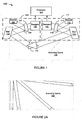
- Figure 1 is a block diagram of a position determination system 100 that is responsive to a retro-reflective object 110 located within a scanning space 130 according to the invention.
- the purpose of Figure 1 is to illustrate how coordinates of the retro-reflective object 110 are calculated using frequency values of dispersed beams that are associated with respective radial portions of the scanning space 130.
- the system 100 can calculate angular positions of the retro-reflective object 110 and triangulate coordinates of the retro-reflective object 110 using the angular positions.
- the relationship between the frequency values of the dispersed beams and the radial position of the retro-reflective object 110 within the scanning space 130 is described later with reference to Figures 2A and 2B . Until the relationship is described, it is simply assumed that such a relationship exists.
- the system 100 includes a first angular position determination subsystem 101, a second angular position determination subsystem 111, and a processor 120.
- processors are well known in the computer arts. Accordingly a detailed description of the processor 120 is not provided herein. It should be noted, however, that processors are typically coupled to storage media that includes instructions for executing functions. The storage medium may or may not be necessary if the instructions are implemented in hardware. Accordingly, the processor 120, as used herein, could be a hardware device with no associated storage medium (other than optional registers). Moreover, the processor 120, as used herein, could actually be a multi-processor or multiple processors.
- the processor 120 receives as input the output of the two subsystems 101 and 111.
- the output of the two subsystems 101 and 111 are frequency values.
- the processor 120 determines angular positions of the retro-reflective object 110 that correspond to the frequency values.
- the processor 120 uses the angular positions to triangulate coordinates of the retro-reflective object 110 and thereby determine the position of the retro-reflective object 110.
- the subsystems 101 and 111 have independent processors (not shown) that determine angular position from a frequency and output the angular position to the processor 120, which uses the angular positions to triangulate coordinates of the retro-reflective object 110 and thereby determine the position of the retro-reflective object 110.
- the processor 120 is coupled to an output device, such as a computer monitor (not shown). Since the processor calculates the coordinates of the retro-reflective object 110 within the scanning space 130, movement of the retro-reflective object 110 within the scanning space 130 may be represented on the output device. In an alternative, the movement of the retro-reflective object 110 is recorded in storage media. In another alternative, the retro-reflective object 110 is used as a computer input device.
- the retro-reflective object 110 may be practically any retro-reflective object, including a retro-reflective mouse or touch screen input device, or even a pen with a retro-reflective surface at the writing end or retro-reflective tape, attached to a person's finger or an arbitrary object.
- the retro-reflective object 110 can be tetherless, consume no power, contain no moving parts, and be as inexpensive as, for example, retro-reflective tape.
- the subsystem 101 includes an electromagnetic (EM) source 102, a partially reflective surface 103, a beam dispersion device (BDD) 104, and a receptor 106.
- the EM source 102 may be a narrowband tunable or swept source, or a broadband optical source, that utilizes a light emitting diode (LED), optical amplifier, incandescent lamp or some other device or devices for providing an EM beam. Exemplary embodiments that utilize broadband and narrowband tunable sources are described later with reference to Figures 3A and 3B , respectively.
- the EM source could also be an optical fiber or some other device for providing an EM beam.
- the partially reflective surface 103 may be a partially reflective mirror, a polarizing beam splitter, or some other partially reflective surface.
- the BDD 104 may be a diffraction grating, a prism, a holographic element, or some other,beam dispersion device. Exemplary embodiments that utilize a diffraction grating are described later with reference to Figures 3A and 3B .
- the receptor 106 may be a wavemeter, a photodetector, or some other frequency measuring or EM radiation-detecting device. Exemplary embodiments that utilize a wavemeter and a photodetector are described later with reference to Figure 3A and Figure 3B , respectively.
- Retro-reflective object 110 An EM beam that is incident on the retro-reflective object 110 is reflected back in the direction from which it came. Retro-reflection is well-known in optical physics. A retro-reflective object reflects EM radiation in a direction parallel to the incident direction. Retro-reflective objects can be manufactured using angled gold-plated mirrors, or in low cost arrays in the form of geometric shapes on tape or spray.
- the EM source 102 provides an EM beam 108 that is incident on the partially reflective surface 103. A portion of the EM beam 108 is reflected toward the BDD 104. If the EM beam 108 is from a broadband source, the BDD 104 disperses the beam across multiple frequencies. If, on the other hand, the EM beam 108 is from a tunable (or swept) source, then the tunable source provides an EM beam that has a time-dependent variable frequency. In other words, over a period of time, the tunable source should jump through a range of frequencies in turn. The BDD 104 disperses the EM beam at an angle of diffraction that is related to the frequency of the EM beam.
- the beam After a beam's initial reflection off of the BDD 104, the beam is referred to herein as a "dispersed beam". Because the relationship between frequency and the angle of diffraction are critical to position determination, it is necessary to obtain the frequency-dependent characteristics of the particular dispersion device. The information can be obtained through, for example, diffraction charts, diffraction measurements or other techniques.
- the BDD 104 directs the dispersed beam into a scanning space 130.
- the retro-reflective object 110 should retro-reflect at least a portion of the dispersed beam back toward the BDD 104.
- the BDD 104 then redirects the retro-reflected beam toward the partially reflective surface 103. A portion of the retro-reflected beam passes through the partially reflective surface 103 and is detected by the receptor 106.
- the processor 120 receives the output of the receptor 106, which may be either a frequency value (e.g., from a wavemeter) or simply an indication that an EM signal associated with the retro-reflected beam was detected (e.g., from a photodetector). If the receptor 106 is a wavemeter, it measures a frequency (or wavelength) of the retro-reflected beam. If the receptor 106 is a photodetector, then typically the frequency of the EM beam 108 at a time t should be known so that when the receptor 106 detects the retro-reflected beam at time t the frequency of the retro-reflected beam may be inferred.
- a frequency value e.g., from a wavemeter
- simply an indication that an EM signal associated with the retro-reflected beam was detected e.g., from a photodetector
- the subsystem 111 includes an EM source 112, a partially reflective surface 113, a BDD 114, a receptor 116, and an EM beam 118.
- the subsystem 111 is like the subsystem 101. Accordingly, only subsystem 101 is described in detail.
- the subsystems 101 and 111 each determine an angular position of the retro-reflective object 110 (or else output a frequency value from which the processor 120 can determine an angular position). If an additional angular position determination subsystem (not shown) is incorporated into the system 100, a three-dimensional position determination system (not shown) is possible. This system would determine three angular positions of the retro-reflective object 110 and triangulate the spatial coordinates of the retro-reflective object 110 therefrom. Regardless of the number of angular position determination subsystems used, the processor 120 can triangulate the coordinates (spatial coordinates in the case of a three-dimensional embodiment) of the retro-reflective object 110 using the angular positions. Triangulation using angular positions is well-known in the mathematical arts and is not described in detail herein.
- Figures 2A and 2B illustrate the relationship between object coordinates and a dispersed beam according to the invention. Specifically, Figure 2A illustrates the relationship between radial portions of a scanning space 230 and frequencies (or wavelengths) of the respective dispersed beams and Figure 2B illustrates the relationship between coordinates of a retro-reflective object 210 and frequencies of the respective dispersed beams.
- Frequency-dependent dispersion is a well-known phenomenon. The phenomenon is sometimes illustrated using a prism (a well-known beam dispersion device), with which light is diffracted into a frequency-dependent rainbow pattern.
- Figure 2A shows how a frequency-dependent pattern may be spread out over a scanning space 230.
- a narrowband tunable (or swept) source can provide an EM beam with a frequency that varies with time.
- a first radial portion of the scanning space 230 may be associated with a time 0 and the last radial portion of the scanning space 230 may be associated with a time N.
- the dispersed beam at time 0 should have a frequency f 0 .
- the dispersed beam should have a frequency f 1 .
- the dispersed beam should have a frequency f t .
- the dispersed beam should have a frequency f N .
- the swept source After time N, the swept source starts over with the frequency f 0 (or starts over at some arbitrary frequency between f 0 and f N .) In this way, the dispersed beams cover radial portions of the scanning space 230 in such a way that radial portions of the scanning space 230 are associated with a frequency. If a broadband source is used instead of a swept source, the EM beam is dispersed simultaneously into the scanning space 230. Angular displacement of a retro-reflective object is determined as a function of the dispersion angle of a particular frequency, as described with reference to Figure 2B .
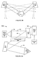
- Figure 2B includes a BDD 204 (similar to BDD 104 of Figure 1 ) and a BDD 214 (similar to BDD 114 of Figure 1 ).
- an EM beam dispersed by the BDD 204 is assumed to come from a narrowband tunable (or swept) source.
- the BDD 204 disperses the EM beam by frequency. That is, the angle of diffraction of the dispersed beam is a function of the frequency (or wavelength) of the dispersed beam.
- the EM source sweeps from red to violet before starting over again at red (assuming the EM beam is in the visible light frequency range).
- the BDD 204 disperses the EM beam into a dispersed beam having a frequency of f t .
- the dispersed beam is directed toward a radial portion of a scanning area that corresponds to the frequency f t . If the retro-reflective object 210 is in the portion of the scanning area that corresponds to the frequency f t then the retro-reflective object 210 should retro-reflect the dispersed beam of frequency f t back toward the BDD 204 and eventually to a receptor (not shown) as described with reference to Figure 1 .
- the BDD 214 functions in much the same manner as the BDD 204.
- frequencies of the dispersed beams dispersed by the BDD 214 are represented as f 0' through f N' .
- the dispersed beam having a frequency of f t is retro-reflected from the retro-reflective object 210 back toward the BDD 204.
- the dispersed beam having a frequency of f t' is retro-reflected from the retro-reflective object 210 back toward the BDD 214.
- each of these frequencies, f t and f t' are associated with radial positions of the scanning space 230, respective angular positions of the retro-reflective object 210 may be calculated therefrom (assuming the frequencies are measured or otherwise known). Then the coordinates of the retro-reflective object 210 may be triangulated as described previously.
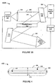
- Figures 3A and 3B are exemplary block diagrams of angular position determination systems according to the invention.
- Figure 3A is intended to illustrate an example of a system 300A that uses a broadband source to determine the position of a retro-reflective object 312.
- Figure 3A also illustrates the use of a polarizing beam splitter (PBS) with a Faraday rotator as an embodiment of the partially reflective surface 103 ( Figure 1 ).
- PBS polarizing beam splitter
- the system 300A is similar to the subsystem 101 ( Figure 1 ) described previously.
- the system 300A includes a broadband source 302, a lens 304, a PBS 306, a Faraday rotator 308, a diffraction grating (DG) 310, a wavemeter 314, and a processor 316.
- DG diffraction grating
- the broadband source 302 provides an EM beam to the lens 304, which focuses the beam onto a path 320 toward the PBS 306.
- the PBS 306 reflects EM radiation having a first polarization state, while allowing EM radiation that has a second polarization state that is orthogonal to the first polarization state to pass through it.
- the broadband source 302 is presumed for the purpose of this example to provide an EM beam that has the first polarization state.
- the polarization state of the EM beam may be polarized using a polarizer (not shown) that is located between the broadband source 302 and the PBS 306.
- the broadband source 302 may provide an unpolarized EM beam, wherein a portion of the EM beam passes through the PBS 306 and a portion of the EM beam is reflected.
- the PBS 306 reflects at least a portion of the EM beam along the path 330 toward the Faraday rotator 308.
- the Faraday rotator 308 rotates the polarization state of the EM beam by 45° as the beam passes through it toward the DG 310.
- a significance of this rotation is that a beam that returns along the path 330 will have its polarization state rotated again by 45°, for a total rotation of 90°, which is orthogonal to the first polarization state (i.e., orthogonal to the polarization state of EM radiation that is reflected by the PBS 306). Accordingly, the beam will pass through the PBS 306 on its return trip.
- the DG 310 is configured to disperse the EM beam at frequency-dependent angles.
- An exemplary dispersed beam is directed along a path 340.
- the retro-reflective object 312 is located in the path 340.
- the DG 310 would typically simultaneously disperse an EM beam from a broadband source across a scanning space, only the portion of the dispersed beam that is incident on the retro-reflective object 312 is illustrated so as to avoid cluttering the figure.
- the retro-reflective object 312 retro-reflects the portion of the dispersed beam back along the path 340 to the DG 310.
- the DG 310 then redirects the retro-reflected beam back in the direction from which the EM beam first came - in other words, onto the path 330, through the Faraday reflector 308, to the PBS 306.
- the PBS 306 initially reflected the EM beam because the polarization state of the EM beam was a first polarization state. Since the beam passed through the Faraday reflector 308 on its path toward the retro-reflective object 312, and the retro-reflected beam passed through the Faraday reflector 308 on the return path from the retro-reflective object 312, the retro-reflected beam is in the second polarization state (i.e., is orthogonal to the first polarization state). Accordingly, as previously described, the PBS 306 now allows the retro-reflected beam to pass through the PBS 306 on path 350 to the wavemeter 314. The wavemeter 314 measures a frequency of the retro-reflected beam. The processor 316 receives the measured frequency from the wavemeter 314 and determines the angular position of the retro-reflective object 312 using the measured frequency.
- Figure 3B is intended to illustrate an example of a system 300B that uses a narrowband tunable source to determine the position of the retro-reflective object 312.
- the system 300B is similar to the subsystem 300A ( Figure 3A ) described previously, but uses a tunable source 352 in place of a broadband source 302 and a photodetector 364 in place of a wavemeter 314.
- the tunable source 352 provides an EM beam having a time-dependent variable frequency along the path 360 to the PBS 306, which redirects the EM beam along the path 370 through the Faraday rotator 308 to the DG 310.
- the DG 310 disperses the EM beam at an angle that is dependent upon the frequency of the EM beam. Since the EM beam in this case is of a variable frequency, the EM beam is dispersed as a dispersed beam at an angle associated with the variable frequency. Assuming that the retro-reflective object 312 is positioned in the angular position associated with the dispersed beam, the DG 310 disperses the EM beam along the path 380 to the retro-reflective object 312.
- the retro-reflective object 312 retro-reflects the dispersed beam back to the DG 310 along the path 380.
- the DG 310 then redirects the retro-reflected beam back along the path 370 through the Faraday rotator 308 to the PBS 306, through which the retro-reflected beam passes to the photodetector 364, where the retro-reflected beam is detected.
- the tunable source 352 may have a known frequency f t , where the frequency is obtained by a known technique.
- the known techniques include utilizing tunable laser sources that have their frequency controlled by an applied voltage where there is a fixed relationship between the voltage applied, for example, to a MEMs actuator integrated into the laser and the frequency output of the laser.
- a wavemeter may be integrated into a laser and one or more optical etalons sample a portion of the laser output to provide signals to one or more detectors whose outputs are used to determine the optical frequency.
- the photodetector 364 detects the retro-reflected beam at time t, it may be inferred that the retro-reflected beam is associated with an EM beam having a frequency f t .
- the processor 376 determines the angular position of the retro-reflective object 312 using the known frequency f t when output from the photodetector indicates the retro-reflected beam has been detected at time t. It should be noted that it takes a relatively small amount of time for the EM beam from the tunable source 352 to reach the photodetector 364 so, for the purposes of example, the delay is ignored.
- a wavemeter may be used in place of a photodetector with a tunable source.
- Wavemeters are well-known and can be constructed from optical etalons, or through the use of dispersive devices such as optical diffraction gratings or any device that exhibits a measurable property, such as optical transmission, that depends on wavelength.
- the system may receive no feedback from the tunable source regarding the frequency of the tunable source at time t. Accordingly, the wavemeter measures the frequency of each detected retro-reflected beam.
- two angular positions may be determined with respect to a retro-reflective object, and the coordinates of the retro-reflective object derived therefrom, as described previously with reference to Figure 1 .
- a retro-reflective object may have a limited tracking range of the retro-reflective object in a direction orthogonal to the two-dimensional scanning space. This limited tracking range may be improved by using an elliptical EM beam, as described with reference to Figure 4 .
- Figure 4 illustrates the tracking range along a direction orthogonal to a two-dimensional scanning space according to the invention.
- the scanning space includes a first scanning space 402 and a second scanning space 404.
- a coordinate axis 410 is orthogonal to the scanning spaces.
- a first point 420 is located inside the first scanning space 402 and a second point 430 is located inside the second scanning space 404.
- a system associated with the first scanning space 402 would be able to detect the position of a retro-reflector at point 420, but not at point 430.
- This problem can be ameliorated somewhat by enlarging the scanning space in a third (orthogonal) dimension by using expanded beams such as, for example, elliptical EM beams.
- the enlarged scanning space is illustrated by the second scanning space 404.
- a retro-reflector located at point 430 would be detectable by the system.
- the tolerance of the system is improved with respect to a retro-reflective object being raised or lowered away from the scanning space 402
- the system is still referred to as two-dimensional because the position of the retro-reflective object in the orthogonal direction is not measured.
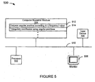
- FIG. 5 is a block diagram of an EM position determination computer system 500 according to the invention.
- the system 500 includes a processor 502, a computer readable medium 504, an input device 506, and a monitor 508. Each of the components is coupled to a bus 510.
- the computer readable medium includes program instructions 512 and 514.
- the processor 502 executes the program instructions.
- the program instructions 512 compute an angular position according to a frequency value when the input device 506 provides an input indicating an EM signal has been detected.
- the program instructions 514 triangulate coordinates using two or more angular positions.
- the coordinates are output to the bus 510 for, for example, display as an arrow, a cursor, or some other indicator on the monitor 508.
- the coordinates may be in two or three dimensions.
- the system 500 may be used with the system 100 ( Figure 1 ).
- the processor 502 includes the processor 120 ( Figure 1 ) and the input device 506 includes the subsystems 101 and 111 ( Figure 1 ).
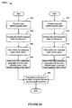
- FIG. 6A illustrates a flowchart 600A of a method for determining the position of a retro-reflective object in a two-dimensional scanning space.
- the flowchart 600A has two starting points.
- the flowchart 600A starts from the first starting point with providing a first EM beam at step 602, dispersing the EM beam by frequency at step 604, retro-reflecting the dispersed beam off of a retro-reflective object at step 606, and determining a first angular position of the retro-reflective object from the frequency of the retro-reflected beam at step 608.
- the first EM beam may be from a broadband source, in which case, at a time t, the EM beam is dispersed simultaneously across a range of wavelengths. If the EM beam is from a swept source, the EM beam is dispersed across a range of wavelengths as a function of time.
- the flowchart 600A starts from the second starting point with providing a second EM beam at step 612, dispersing the EM beam into a dispersed beam at step 614, retro-reflecting the dispersed beam off of a retro-reflective object at step 616, and determining a second angular position of the retro-reflective object from the frequency of the retro-reflected beam at step 618.
- the second EM beam may be from a broadband or swept source.
- the coordinates of the retro-reflective object may be triangulated using the first and second angular positions at step 620. Then the flowchart 600A ends.
- Figure 6B illustrates a flowchart 600B of a method for determining the position of a retro-reflective object in a two- or three-dimensional scanning space.
- one or more EM beams are provided.
- the EM beams are dispersed into respective dispersed beams.
- the respective dispersed beams are retro-reflected off a retro-reflective object.
- the respective angular positions of the object are determined using a frequency associated with the respective retro-reflected beams.
- the coordinates of the object are triangulated using two or more of the respective angular positions. If three or more of the respective angular positions are used, the spatial (i.e., three-dimensional) coordinates of the object may be triangulated.
- disperse when used with reference to an EM beam is defined broadly herein to include reflecting, diffracting, or otherwise directing the EM beam. Dispersing the EM beam could include splitting the EM beam into frequency-dependent bands or, if the EM beam has a (central) frequency, redirecting the EM beam according to its frequency.
- broadband source is defined broadly to include broadband sources that provide spectrally broadband EM beams.
Landscapes
- Engineering & Computer Science (AREA)
- Physics & Mathematics (AREA)
- General Engineering & Computer Science (AREA)
- Theoretical Computer Science (AREA)
- Electromagnetism (AREA)
- General Physics & Mathematics (AREA)
- Human Computer Interaction (AREA)
- Computer Networks & Wireless Communication (AREA)
- Radar, Positioning & Navigation (AREA)
- Remote Sensing (AREA)
- Length Measuring Devices By Optical Means (AREA)
Description
- The present invention relates generally to position determination systems, and more particularly to optical position determination systems.
- Mechanical mice are well known to computer users as a useful tool for positioning a cursor and selecting functions in different applications. These mechanical mice use a ball and related sensors to detect relative motion. However, mechanical mice use relative coordinate tracking, typically have moving parts, are limited to two-dimensional position input, have low resolution, and only work on certain surfaces.
- Optical mice use light to detect relative motion. Typically, an optical mouse has a light source, such as a light emitting diode (LED), for illuminating a surface, such as a mouse pad or surface of a table. The light strikes the surface and a portion of the light is reflected. The optical mouse has an on-board detector for detecting the reflected light. Based on the reflected light, an electronic computation unit determines the relative motion of the optical mouse. While optical mice overcome some of the limitations of mechanical mice, they too are limited to two-dimensional position input, use relative coordinate tracking, and do not work on certain surfaces, such as mirrors. Moreover, the LED and electronic computation necessitates the use of a power source in optical mice.
-
EP-A2-0366112 discloses a coordinate input apparatus which is freed from restrictions of a conventional tablet and is thereby capable of being applied to a large sized two dimensional coordinate plane as well as a small sized one. It comprises a reflection type position indicator, a light source portion and a calculating portion whereby when the reflection type position indicator is positioned on the coordinate plane for the purpose of designating a coordinate, the light source portion disposed on the coordinate plane emits incident light with angularly scanning from two points which are disposed away from each other on a reference line toward the reflection type position indicator. The light source portion includes sensors and transmits ain output signal when it receives light which passes reversely as a result of reflection on the position indicator. The calculating portion calculates the angles between the ref erence and the detected light beams. The coordinate designated by the position indicator is calculated in accordance with a principle of triangulation by using the thus obtained angles and the distance between the two points. -
US-A-6008798 relates to a method of determining an object's position and associated apparatus, which provide positional information in a form that may be conveniently communicated to a computer system to calculate the object's position. In a disclosed embodiment, representatively incorporated in a computer keyboard, a method of determining an object's position includes forming an optical grid of overlapping beacons and detecting reflections of the beacons produce by the object when it intersects the grid. The disclosed embodiment utilizes two focused beacons to produce the optical grid. -
EP-A-1100041 disclose an optical digitizer which has a function to recognize kinds of pointing instruments, allowing an input by a finger or by a pen, is provided. The optical digitizer includes: a light source to emit a light ray; an image taking device which is arranged in a periphery of a coordinate plane, and which converts an image of the pointing instrument into an electrical signal after taking an image of the pointing instrument by using the light ray of the light source; a computing device to compute the pointing position coordinates after processing the converted electrical signal by the image taking device; a polarizing device to polarize the light ray emitted by the light source into a first polarized light ray or a second polarized light ray; a switching device to switch the irradiating light on the coordinate plane to the first polarized light or the second polarized light; a retroreflective material with retroreflective characteristics, which is installed at a frame of the coordinate plane; a polarizing film with a transmitting axis which causes the first polarized light ray to be transmitted; and a judging device to judge the pointing instrument as the first pointing instrument when the image of the pointing instrument is taken by the first polarized light ray, and to judge the pointing instrument as the second pointing instrument when the image of the pointing instrument is taken by the second polarized light ray. -
US-A-4184767 relates to a frequency agile optical radar system including a frequency agile laser source coupled with an extra-cavity dispersive element in such a manner as to radiate into space specific optical frequencies correlated with specific elevation angles measures, from the horizontal. Laser radiation reflected from an object in space is detected by a staring detector system and the wavelength of the reflected optical energy determined therefrom. The elevation angle of the object in space is correlated with the optical frequency determination and coupled together with target range and aximuth angle so that the position and range to an object in space may be determined. - A technique for position determination utilizes frequency-dependent diffraction (also referred to as dispersion) to determine the angular position of a retro-reflective object within a scanning space. The technique involves dispersing an electromagnetic (EM) beam into a scanning space by frequency. If a retro-reflective object is located within the scanning space, the object will retro-reflect a portion of the dispersed beam having a frequency that is associated with the angular position of the retro-reflective object within the scanning space. The frequency of the retro-reflected beam is used to determine the angular position of the retro-reflective object within the scanning space. When a second beam is dispersed into the scanning space and a portion of the second beam is retro-reflected in the manner just described, a second angular position of the retro-reflective object can be found. Coordinates of the retro-reflective object are determinable by triangulation using the two angular positions. These are absolute, as opposed to relative, coordinates. Spatial (three-dimensional) coordinates of the retro-reflective object are determinable by triangulation using three or more angular positions.
-
-
Figure 1 is a block diagram of a position determination system that is responsive to a retro-reflective object according to the invention. -
Figures 2A and2B illustrate the relationship between object coordinates and an electromagnetic beam dispersed into a scanning space according to the invention. -
Figures 3A and3B are exemplary block diagrams of angular position determination systems according to the invention. -
Figure 4 illustrates the tracking range along a direction orthogonal to a two-dimensional scanning space according to the invention. -
Figure 5 is a block diagram of a position determination computer system according to the invention. -
Figures 6A and6B depict flowcharts of methods for determining positions of retro-reflective objects according to the invention. - Throughout the description, similar reference numbers may be used to identify similar elements.
- As shown in the drawings for the purposes of illustration, the invention involves position determination. In an embodiment, the invention relies on frequency-dependent diffraction to determine an angular position of a retro-reflective object within a scanning space.
-
Figure 1 is a block diagram of aposition determination system 100 that is responsive to a retro-reflective object 110 located within ascanning space 130 according to the invention. The purpose ofFigure 1 is to illustrate how coordinates of the retro-reflective object 110 are calculated using frequency values of dispersed beams that are associated with respective radial portions of thescanning space 130. Using the frequency values, thesystem 100 can calculate angular positions of the retro-reflective object 110 and triangulate coordinates of the retro-reflective object 110 using the angular positions. (The relationship between the frequency values of the dispersed beams and the radial position of the retro-reflective object 110 within thescanning space 130 is described later with reference toFigures 2A and2B . Until the relationship is described, it is simply assumed that such a relationship exists.) - The
system 100 includes a first angularposition determination subsystem 101, a second angularposition determination subsystem 111, and aprocessor 120. Processors are well known in the computer arts. Accordingly a detailed description of theprocessor 120 is not provided herein. It should be noted, however, that processors are typically coupled to storage media that includes instructions for executing functions. The storage medium may or may not be necessary if the instructions are implemented in hardware. Accordingly, theprocessor 120, as used herein, could be a hardware device with no associated storage medium (other than optional registers). Moreover, theprocessor 120, as used herein, could actually be a multi-processor or multiple processors. - The
processor 120 receives as input the output of the twosubsystems subsystems processor 120 determines angular positions of the retro-reflective object 110 that correspond to the frequency values. Theprocessor 120 then uses the angular positions to triangulate coordinates of the retro-reflective object 110 and thereby determine the position of the retro-reflective object 110. In an alternative embodiment, thesubsystems processor 120, which uses the angular positions to triangulate coordinates of the retro-reflective object 110 and thereby determine the position of the retro-reflective object 110. - In an embodiment, the
processor 120 is coupled to an output device, such as a computer monitor (not shown). Since the processor calculates the coordinates of the retro-reflective object 110 within thescanning space 130, movement of the retro-reflective object 110 within thescanning space 130 may be represented on the output device. In an alternative, the movement of the retro-reflective object 110 is recorded in storage media. In another alternative, the retro-reflective object 110 is used as a computer input device. Advantageously, the retro-reflective object 110 may be practically any retro-reflective object, including a retro-reflective mouse or touch screen input device, or even a pen with a retro-reflective surface at the writing end or retro-reflective tape, attached to a person's finger or an arbitrary object. The retro-reflective object 110 can be tetherless, consume no power, contain no moving parts, and be as inexpensive as, for example, retro-reflective tape. - The
subsystem 101 includes an electromagnetic (EM)source 102, a partiallyreflective surface 103, a beam dispersion device (BDD) 104, and areceptor 106. TheEM source 102 may be a narrowband tunable or swept source, or a broadband optical source, that utilizes a light emitting diode (LED), optical amplifier, incandescent lamp or some other device or devices for providing an EM beam. Exemplary embodiments that utilize broadband and narrowband tunable sources are described later with reference toFigures 3A and3B , respectively. The EM source could also be an optical fiber or some other device for providing an EM beam. The partiallyreflective surface 103 may be a partially reflective mirror, a polarizing beam splitter, or some other partially reflective surface. Exemplary embodiments that utilize a polarizing beam splitter are described later with reference toFigures 3A and3B . TheBDD 104 may be a diffraction grating, a prism, a holographic element, or some other,beam dispersion device. Exemplary embodiments that utilize a diffraction grating are described later with reference toFigures 3A and3B . Thereceptor 106 may be a wavemeter, a photodetector, or some other frequency measuring or EM radiation-detecting device. Exemplary embodiments that utilize a wavemeter and a photodetector are described later with reference toFigure 3A andFigure 3B , respectively. - An EM beam that is incident on the retro-
reflective object 110 is reflected back in the direction from which it came. Retro-reflection is well-known in optical physics. A retro-reflective object reflects EM radiation in a direction parallel to the incident direction. Retro-reflective objects can be manufactured using angled gold-plated mirrors, or in low cost arrays in the form of geometric shapes on tape or spray. - In operation, the
EM source 102 provides anEM beam 108 that is incident on the partiallyreflective surface 103. A portion of theEM beam 108 is reflected toward theBDD 104. If theEM beam 108 is from a broadband source, theBDD 104 disperses the beam across multiple frequencies. If, on the other hand, theEM beam 108 is from a tunable (or swept) source, then the tunable source provides an EM beam that has a time-dependent variable frequency. In other words, over a period of time, the tunable source should jump through a range of frequencies in turn. TheBDD 104 disperses the EM beam at an angle of diffraction that is related to the frequency of the EM beam. After a beam's initial reflection off of theBDD 104, the beam is referred to herein as a "dispersed beam". Because the relationship between frequency and the angle of diffraction are critical to position determination, it is necessary to obtain the frequency-dependent characteristics of the particular dispersion device. The information can be obtained through, for example, diffraction charts, diffraction measurements or other techniques. - Whether the EM beam is from a narrowband or broadband source, the
BDD 104 directs the dispersed beam into ascanning space 130. When the retro-reflective object 110 is present within thescanning space 130, assuming the dispersed beam is directed toward the radial portion of thescanning space 130 in which the retro-reflective object 110 is positioned, the retro-reflective object 110 should retro-reflect at least a portion of the dispersed beam back toward theBDD 104. TheBDD 104 then redirects the retro-reflected beam toward the partiallyreflective surface 103. A portion of the retro-reflected beam passes through the partiallyreflective surface 103 and is detected by thereceptor 106. Theprocessor 120 receives the output of thereceptor 106, which may be either a frequency value (e.g., from a wavemeter) or simply an indication that an EM signal associated with the retro-reflected beam was detected (e.g., from a photodetector). If thereceptor 106 is a wavemeter, it measures a frequency (or wavelength) of the retro-reflected beam. If thereceptor 106 is a photodetector, then typically the frequency of theEM beam 108 at a time t should be known so that when thereceptor 106 detects the retro-reflected beam at time t the frequency of the retro-reflected beam may be inferred. - The
subsystem 111 includes anEM source 112, a partiallyreflective surface 113, aBDD 114, areceptor 116, and anEM beam 118. Thesubsystem 111 is like thesubsystem 101. Accordingly, only subsystem 101 is described in detail. - As previously mentioned, the
subsystems processor 120 can determine an angular position). If an additional angular position determination subsystem (not shown) is incorporated into thesystem 100, a three-dimensional position determination system (not shown) is possible. This system would determine three angular positions of the retro-reflective object 110 and triangulate the spatial coordinates of the retro-reflective object 110 therefrom. Regardless of the number of angular position determination subsystems used, theprocessor 120 can triangulate the coordinates (spatial coordinates in the case of a three-dimensional embodiment) of the retro-reflective object 110 using the angular positions. Triangulation using angular positions is well-known in the mathematical arts and is not described in detail herein. -
Figures 2A and2B illustrate the relationship between object coordinates and a dispersed beam according to the invention. Specifically,Figure 2A illustrates the relationship between radial portions of ascanning space 230 and frequencies (or wavelengths) of the respective dispersed beams andFigure 2B illustrates the relationship between coordinates of a retro-reflective object 210 and frequencies of the respective dispersed beams. - Frequency-dependent dispersion (or diffraction) is a well-known phenomenon. The phenomenon is sometimes illustrated using a prism (a well-known beam dispersion device), with which light is diffracted into a frequency-dependent rainbow pattern.
Figure 2A shows how a frequency-dependent pattern may be spread out over ascanning space 230. - A narrowband tunable (or swept) source can provide an EM beam with a frequency that varies with time. When an EM beam is dispersed into the
scanning space 230 over time, a first radial portion of thescanning space 230 may be associated with a time 0 and the last radial portion of thescanning space 230 may be associated with a time N. Accordingly, the dispersed beam at time 0 should have a frequency f0. One time increment later, the dispersed beam should have a frequency f1. At a time t, the dispersed beam should have a frequency ft. At time N, the dispersed beam should have a frequency fN. After time N, the swept source starts over with the frequency f0 (or starts over at some arbitrary frequency between f0 and fN.) In this way, the dispersed beams cover radial portions of thescanning space 230 in such a way that radial portions of thescanning space 230 are associated with a frequency. If a broadband source is used instead of a swept source, the EM beam is dispersed simultaneously into thescanning space 230. Angular displacement of a retro-reflective object is determined as a function of the dispersion angle of a particular frequency, as described with reference toFigure 2B . -
Figure 2B includes a BDD 204 (similar toBDD 104 ofFigure 1 ) and a BDD 214 (similar toBDD 114 ofFigure 1 ). For the purposes of illustration, an EM beam dispersed by theBDD 204 is assumed to come from a narrowband tunable (or swept) source. TheBDD 204 disperses the EM beam by frequency. That is, the angle of diffraction of the dispersed beam is a function of the frequency (or wavelength) of the dispersed beam. Using the prism example again as a coarse example, the EM source sweeps from red to violet before starting over again at red (assuming the EM beam is in the visible light frequency range). In this way, at any given time t, theBDD 204 disperses the EM beam into a dispersed beam having a frequency of ft. The dispersed beam is directed toward a radial portion of a scanning area that corresponds to the frequency ft. If the retro-reflective object 210 is in the portion of the scanning area that corresponds to the frequency ft then the retro-reflective object 210 should retro-reflect the dispersed beam of frequency ft back toward theBDD 204 and eventually to a receptor (not shown) as described with reference toFigure 1 . - The BDD 214 functions in much the same manner as the
BDD 204. InFigure 2B , frequencies of the dispersed beams dispersed by the BDD 214 are represented as f0' through fN'. As previously described, at a time t, the dispersed beam having a frequency of ft is retro-reflected from the retro-reflective object 210 back toward theBDD 204. Similarly, at a time t', the dispersed beam having a frequency of ft' is retro-reflected from the retro-reflective object 210 back toward the BDD 214. Since each of these frequencies, ft and ft', are associated with radial positions of thescanning space 230, respective angular positions of the retro-reflective object 210 may be calculated therefrom (assuming the frequencies are measured or otherwise known). Then the coordinates of the retro-reflective object 210 may be triangulated as described previously. -
Figures 3A and3B are exemplary block diagrams of angular position determination systems according to the invention.Figure 3A is intended to illustrate an example of asystem 300A that uses a broadband source to determine the position of a retro-reflective object 312.Figure 3A also illustrates the use of a polarizing beam splitter (PBS) with a Faraday rotator as an embodiment of the partially reflective surface 103 (Figure 1 ). Note that the PBS and Faraday rotator combination may be used whether the source is a broadband source, as inFigure 3A , or a narrowband tunable source, as inFigure 3B . Thesystem 300A is similar to the subsystem 101 (Figure 1 ) described previously. Thesystem 300A includes abroadband source 302, alens 304, aPBS 306, aFaraday rotator 308, a diffraction grating (DG) 310, awavemeter 314, and aprocessor 316. - In operation, the
broadband source 302 provides an EM beam to thelens 304, which focuses the beam onto apath 320 toward thePBS 306. ThePBS 306 reflects EM radiation having a first polarization state, while allowing EM radiation that has a second polarization state that is orthogonal to the first polarization state to pass through it. Thebroadband source 302 is presumed for the purpose of this example to provide an EM beam that has the first polarization state. In an alternative, instead of thebroadband source 302 providing an EM beam that has the first polarization state, the polarization state of the EM beam may be polarized using a polarizer (not shown) that is located between thebroadband source 302 and thePBS 306. In another alternative, thebroadband source 302 may provide an unpolarized EM beam, wherein a portion of the EM beam passes through thePBS 306 and a portion of the EM beam is reflected. In any case, thePBS 306 reflects at least a portion of the EM beam along thepath 330 toward theFaraday rotator 308. TheFaraday rotator 308 rotates the polarization state of the EM beam by 45° as the beam passes through it toward theDG 310. A significance of this rotation is that a beam that returns along thepath 330 will have its polarization state rotated again by 45°, for a total rotation of 90°, which is orthogonal to the first polarization state (i.e., orthogonal to the polarization state of EM radiation that is reflected by the PBS 306). Accordingly, the beam will pass through thePBS 306 on its return trip. - The
DG 310 is configured to disperse the EM beam at frequency-dependent angles. An exemplary dispersed beam is directed along apath 340. The retro-reflective object 312 is located in thepath 340. Although theDG 310 would typically simultaneously disperse an EM beam from a broadband source across a scanning space, only the portion of the dispersed beam that is incident on the retro-reflective object 312 is illustrated so as to avoid cluttering the figure. The retro-reflective object 312 retro-reflects the portion of the dispersed beam back along thepath 340 to theDG 310. TheDG 310 then redirects the retro-reflected beam back in the direction from which the EM beam first came - in other words, onto thepath 330, through theFaraday reflector 308, to thePBS 306. - As previously described, the
PBS 306 initially reflected the EM beam because the polarization state of the EM beam was a first polarization state. Since the beam passed through theFaraday reflector 308 on its path toward the retro-reflective object 312, and the retro-reflected beam passed through theFaraday reflector 308 on the return path from the retro-reflective object 312, the retro-reflected beam is in the second polarization state (i.e., is orthogonal to the first polarization state). Accordingly, as previously described, thePBS 306 now allows the retro-reflected beam to pass through thePBS 306 onpath 350 to thewavemeter 314. Thewavemeter 314 measures a frequency of the retro-reflected beam. Theprocessor 316 receives the measured frequency from thewavemeter 314 and determines the angular position of the retro-reflective object 312 using the measured frequency. -
Figure 3B is intended to illustrate an example of asystem 300B that uses a narrowband tunable source to determine the position of the retro-reflective object 312. Thesystem 300B is similar to thesubsystem 300A (Figure 3A ) described previously, but uses a tunable source 352 in place of abroadband source 302 and aphotodetector 364 in place of awavemeter 314. - In operation, the tunable source 352 provides an EM beam having a time-dependent variable frequency along the
path 360 to thePBS 306, which redirects the EM beam along thepath 370 through theFaraday rotator 308 to theDG 310. TheDG 310 disperses the EM beam at an angle that is dependent upon the frequency of the EM beam. Since the EM beam in this case is of a variable frequency, the EM beam is dispersed as a dispersed beam at an angle associated with the variable frequency. Assuming that the retro-reflective object 312 is positioned in the angular position associated with the dispersed beam, theDG 310 disperses the EM beam along thepath 380 to the retro-reflective object 312. The retro-reflective object 312 retro-reflects the dispersed beam back to theDG 310 along thepath 380. TheDG 310 then redirects the retro-reflected beam back along thepath 370 through theFaraday rotator 308 to thePBS 306, through which the retro-reflected beam passes to thephotodetector 364, where the retro-reflected beam is detected. - Unlike as was the case with the broadband source 302 (
Figure 3A ), at time t, the tunable source 352 may have a known frequency ft, where the frequency is obtained by a known technique. The known techniques include utilizing tunable laser sources that have their frequency controlled by an applied voltage where there is a fixed relationship between the voltage applied, for example, to a MEMs actuator integrated into the laser and the frequency output of the laser. Alternatively, a wavemeter may be integrated into a laser and one or more optical etalons sample a portion of the laser output to provide signals to one or more detectors whose outputs are used to determine the optical frequency. By making use of one of these known techniques, the frequency ft of the tunable source 352 at time t is known. Accordingly, if thephotodetector 364 detects the retro-reflected beam at time t, it may be inferred that the retro-reflected beam is associated with an EM beam having a frequency ft. The processor 376 determines the angular position of the retro-reflective object 312 using the known frequency ft when output from the photodetector indicates the retro-reflected beam has been detected at time t. It should be noted that it takes a relatively small amount of time for the EM beam from the tunable source 352 to reach thephotodetector 364 so, for the purposes of example, the delay is ignored. - It should further be noted that a wavemeter may be used in place of a photodetector with a tunable source. Wavemeters are well-known and can be constructed from optical etalons, or through the use of dispersive devices such as optical diffraction gratings or any device that exhibits a measurable property, such as optical transmission, that depends on wavelength. In an alternative embodiment that includes a wavemeter, the system may receive no feedback from the tunable source regarding the frequency of the tunable source at time t. Accordingly, the wavemeter measures the frequency of each detected retro-reflected beam.
- By operating two angular position determination subsystems together, two angular positions may be determined with respect to a retro-reflective object, and the coordinates of the retro-reflective object derived therefrom, as described previously with reference to
Figure 1 . It should be noted that in a two-dimensional embodiment, such a system may have a limited tracking range of the retro-reflective object in a direction orthogonal to the two-dimensional scanning space. This limited tracking range may be improved by using an elliptical EM beam, as described with reference toFigure 4 . -
Figure 4 illustrates the tracking range along a direction orthogonal to a two-dimensional scanning space according to the invention. The scanning space includes afirst scanning space 402 and asecond scanning space 404. A coordinateaxis 410 is orthogonal to the scanning spaces. Afirst point 420 is located inside thefirst scanning space 402 and asecond point 430 is located inside thesecond scanning space 404. - A system associated with the
first scanning space 402 would be able to detect the position of a retro-reflector atpoint 420, but not atpoint 430. This problem can be ameliorated somewhat by enlarging the scanning space in a third (orthogonal) dimension by using expanded beams such as, for example, elliptical EM beams. The enlarged scanning space is illustrated by thesecond scanning space 404. By using, for example, elliptical EM beams, a retro-reflector located atpoint 430 would be detectable by the system. Although the tolerance of the system is improved with respect to a retro-reflective object being raised or lowered away from thescanning space 402, the system is still referred to as two-dimensional because the position of the retro-reflective object in the orthogonal direction is not measured. -
Figure 5 is a block diagram of an EM positiondetermination computer system 500 according to the invention. Thesystem 500 includes aprocessor 502, a computerreadable medium 504, aninput device 506, and amonitor 508. Each of the components is coupled to abus 510. The computer readable medium includesprogram instructions processor 502 executes the program instructions. Theprogram instructions 512 compute an angular position according to a frequency value when theinput device 506 provides an input indicating an EM signal has been detected. Theprogram instructions 514 triangulate coordinates using two or more angular positions. The coordinates are output to thebus 510 for, for example, display as an arrow, a cursor, or some other indicator on themonitor 508. The coordinates may be in two or three dimensions. - The
system 500 may be used with the system 100 (Figure 1 ). In fact, in an embodiment, theprocessor 502 includes the processor 120 (Figure 1 ) and theinput device 506 includes thesubsystems 101 and 111 (Figure 1 ). -
Figure 6A illustrates aflowchart 600A of a method for determining the position of a retro-reflective object in a two-dimensional scanning space. Theflowchart 600A has two starting points. Theflowchart 600A starts from the first starting point with providing a first EM beam atstep 602, dispersing the EM beam by frequency atstep 604, retro-reflecting the dispersed beam off of a retro-reflective object atstep 606, and determining a first angular position of the retro-reflective object from the frequency of the retro-reflected beam atstep 608. The first EM beam may be from a broadband source, in which case, at a time t, the EM beam is dispersed simultaneously across a range of wavelengths. If the EM beam is from a swept source, the EM beam is dispersed across a range of wavelengths as a function of time. - The
flowchart 600A starts from the second starting point with providing a second EM beam atstep 612, dispersing the EM beam into a dispersed beam atstep 614, retro-reflecting the dispersed beam off of a retro-reflective object atstep 616, and determining a second angular position of the retro-reflective object from the frequency of the retro-reflected beam atstep 618. Like the first EM beam, the second EM beam may be from a broadband or swept source. When both the first angular position and the second angular position have been determined (atsteps 608 and 618), the coordinates of the retro-reflective object may be triangulated using the first and second angular positions atstep 620. Then theflowchart 600A ends. -
Figure 6B illustrates aflowchart 600B of a method for determining the position of a retro-reflective object in a two- or three-dimensional scanning space. Atstep 622, one or more EM beams are provided. Atstep 624, the EM beams are dispersed into respective dispersed beams. Atstep 626, the respective dispersed beams are retro-reflected off a retro-reflective object. Atstep 628, the respective angular positions of the object are determined using a frequency associated with the respective retro-reflected beams. Atstep 630, the coordinates of the object are triangulated using two or more of the respective angular positions. If three or more of the respective angular positions are used, the spatial (i.e., three-dimensional) coordinates of the object may be triangulated. - The term disperse when used with reference to an EM beam is defined broadly herein to include reflecting, diffracting, or otherwise directing the EM beam. Dispersing the EM beam could include splitting the EM beam into frequency-dependent bands or, if the EM beam has a (central) frequency, redirecting the EM beam according to its frequency.
- The term broadband source, as used herein, is defined broadly to include broadband sources that provide spectrally broadband EM beams.
- Although specific embodiments of the invention have been described and illustrated, the invention is not to be limited to the specific forms or arrangements of parts as described and illustrated herein. The invention is limited only by the claims.
Claims (7)
- A method for determining the position of an object, comprising:providing (622) one or more electromagnetic (EM) beams;dispersing (624) said one or more EM beams, respectively, into a scanning space by frequency;retro-reflecting (626) at least a portion of said respective dispersed beams off an object positioned within said scanning space; anddetermining (628), in response to frequencies associated with said retro reflected beams, respective angular positions of said object, characterised in thatsaid one or more EM beams are provided by respective broadband sources (302).
- The method of claim 1, further comprising:triangulating (630) coordinates of said object using one or more of said respective angular positions.
- A position determination system, comprising:one or more electromagnetic (EM) sources (102; 112) that provide EM beams (108; 118);one or more beam dispersion devices (104; 114) that respectively dispense said one or more EM beams (108; 118) into a scanning space (130) by frequency, wherein said system (100) is configured to be responsive to a retro-refiective object (110) positioned within said scanning space (130) such that said retro-reflective object (110) retro-reflects, at least a portion of said respective dispersed beams; andone or more receptors (106; 116) that receive said respective retro-reflected beams and provide data for determining respective angular positions of said retro-reflective object, characterised in thatsaid one or more EM sources (106; 116) include respective broadband sources (302) that provide said respective EM beams.
- The system of claim 3, further comprising:a processor (120); in signal communication with said one or more receptors (106; 116), that determines, in response to frequencies associated with said respective retro-reflective beams; said respective angular positions of said retro-reflective object.
- The system of claim 4, wherein:said one or more receptors (106; 116) include respective wavemeters (314) that determine frequencies of said respective retro-reflected beams;if said respective wavemeters (314) detect receipt of said respective retro-reflected beams, said processor (120) uses said frequencies of said respective retro-reflected beams to determine said respective angular positions.
- The system of claim 4, further comprising:one or more partially reflective surfaces (103; 113) that direct said respective EM beams from said one or more EM sources to said one or more beam dispersion devices (104; 114) and, that pass said respective retro-reflected beams to said one or more receptors (106; 116).
- The system of claim 6, wherein said one or more partially reflective surfaces (103; 113) include polarized beam splitters (306), wherein said system further comprises:one or more polarization state rotators (308) positioned between respective polarized beam splitters (106) and said retro-reflected object (110), wherein said polarization state of said respective EM beams causes said respective polarized beam splitters (306) to reflect said respective EM beams, and wherein said one or more polarization state rotators (308) rotate said polarization state of said respective EM beams and said respective retro-reflected beams such that said polarization state of said respective retro-reflected beams causes said respective, polarized beam splitters (306) to pass said respective retro-reflected beams to said respective receptors (106; 116).
Applications Claiming Priority (2)
| Application Number | Priority Date | Filing Date | Title |
|---|---|---|---|
| US10/652,638 US7633633B2 (en) | 2003-08-29 | 2003-08-29 | Position determination that is responsive to a retro-reflective object |
| US652638 | 2003-08-29 |
Publications (3)
| Publication Number | Publication Date |
|---|---|
| EP1510836A2 EP1510836A2 (en) | 2005-03-02 |
| EP1510836A3 EP1510836A3 (en) | 2006-11-29 |
| EP1510836B1 true EP1510836B1 (en) | 2009-04-22 |
Family
ID=34104751
Family Applications (1)
| Application Number | Title | Priority Date | Filing Date |
|---|---|---|---|
| EP04010829A Expired - Fee Related EP1510836B1 (en) | 2003-08-29 | 2004-05-06 | Position determination that is responsive to a retro-reflective object |
Country Status (4)
| Country | Link |
|---|---|
| US (1) | US7633633B2 (en) |
| EP (1) | EP1510836B1 (en) |
| JP (1) | JP4879471B2 (en) |
| DE (1) | DE202004021595U1 (en) |
Families Citing this family (25)
| Publication number | Priority date | Publication date | Assignee | Title |
|---|---|---|---|---|
| WO2005040036A1 (en) * | 2003-10-27 | 2005-05-06 | Bookham Technology Plc | Optical assembly with variable optical attenuator |
| US9679215B2 (en) | 2012-01-17 | 2017-06-13 | Leap Motion, Inc. | Systems and methods for machine control |
| US8638989B2 (en) | 2012-01-17 | 2014-01-28 | Leap Motion, Inc. | Systems and methods for capturing motion in three-dimensional space |
| US9070019B2 (en) | 2012-01-17 | 2015-06-30 | Leap Motion, Inc. | Systems and methods for capturing motion in three-dimensional space |
| US9501152B2 (en) | 2013-01-15 | 2016-11-22 | Leap Motion, Inc. | Free-space user interface and control using virtual constructs |
| US10691219B2 (en) | 2012-01-17 | 2020-06-23 | Ultrahaptics IP Two Limited | Systems and methods for machine control |
| US11493998B2 (en) | 2012-01-17 | 2022-11-08 | Ultrahaptics IP Two Limited | Systems and methods for machine control |
| US20150253428A1 (en) | 2013-03-15 | 2015-09-10 | Leap Motion, Inc. | Determining positional information for an object in space |
| US8693731B2 (en) | 2012-01-17 | 2014-04-08 | Leap Motion, Inc. | Enhanced contrast for object detection and characterization by optical imaging |
| US9285893B2 (en) | 2012-11-08 | 2016-03-15 | Leap Motion, Inc. | Object detection and tracking with variable-field illumination devices |
| US10609285B2 (en) | 2013-01-07 | 2020-03-31 | Ultrahaptics IP Two Limited | Power consumption in motion-capture systems |
| US9626015B2 (en) | 2013-01-08 | 2017-04-18 | Leap Motion, Inc. | Power consumption in motion-capture systems with audio and optical signals |
| US9459697B2 (en) | 2013-01-15 | 2016-10-04 | Leap Motion, Inc. | Dynamic, free-space user interactions for machine control |
| US9696867B2 (en) | 2013-01-15 | 2017-07-04 | Leap Motion, Inc. | Dynamic user interactions for display control and identifying dominant gestures |
| US10620709B2 (en) | 2013-04-05 | 2020-04-14 | Ultrahaptics IP Two Limited | Customized gesture interpretation |
| US9916009B2 (en) | 2013-04-26 | 2018-03-13 | Leap Motion, Inc. | Non-tactile interface systems and methods |
| US9747696B2 (en) | 2013-05-17 | 2017-08-29 | Leap Motion, Inc. | Systems and methods for providing normalized parameters of motions of objects in three-dimensional space |
| US10281987B1 (en) | 2013-08-09 | 2019-05-07 | Leap Motion, Inc. | Systems and methods of free-space gestural interaction |
| US10846942B1 (en) | 2013-08-29 | 2020-11-24 | Ultrahaptics IP Two Limited | Predictive information for free space gesture control and communication |
| US9632572B2 (en) | 2013-10-03 | 2017-04-25 | Leap Motion, Inc. | Enhanced field of view to augment three-dimensional (3D) sensory space for free-space gesture interpretation |
| US9996638B1 (en) | 2013-10-31 | 2018-06-12 | Leap Motion, Inc. | Predictive information for free space gesture control and communication |
| CN105814451A (en) * | 2013-12-10 | 2016-07-27 | 三菱电机株式会社 | Laser radar device |
| US9613262B2 (en) | 2014-01-15 | 2017-04-04 | Leap Motion, Inc. | Object detection and tracking for providing a virtual device experience |
| DE202014103729U1 (en) | 2014-08-08 | 2014-09-09 | Leap Motion, Inc. | Augmented reality with motion detection |
| US11875012B2 (en) | 2018-05-25 | 2024-01-16 | Ultrahaptics IP Two Limited | Throwable interface for augmented reality and virtual reality environments |
Family Cites Families (18)
| Publication number | Priority date | Publication date | Assignee | Title |
|---|---|---|---|---|
| US4184767A (en) | 1975-07-21 | 1980-01-22 | The United States Of America As Represented By The Secretary Of The Navy | Frequency agile optical radar |
| US4845684A (en) | 1986-12-09 | 1989-07-04 | International Business Machines Corporation | Acoustic contact sensor for handwritten computer input |
| JPS63238511A (en) * | 1987-03-27 | 1988-10-04 | Fujitsu Ltd | Stereoscopic method |
| DE68921543T2 (en) | 1988-10-26 | 1995-07-20 | Wacom Co Ltd | Optical coordinate input device and position pointer therefor. |
| US5128794A (en) * | 1990-12-31 | 1992-07-07 | Honeywell Inc. | Scanning laser helmet mounted sight |
| JPH0760360B2 (en) * | 1992-04-10 | 1995-06-28 | 直弘 丹野 | Driving method and driving device for discriminating key board |
| US5309212A (en) * | 1992-09-04 | 1994-05-03 | Yaskawa Electric Corporation | Scanning rangefinder with range to frequency conversion |
| EP0700269B1 (en) * | 1993-04-22 | 2002-12-11 | Image Guided Technologies, Inc. | System for locating relative positions of objects |
| US5786810A (en) | 1995-06-07 | 1998-07-28 | Compaq Computer Corporation | Method of determining an object's position and associated apparatus |
| SE507680C2 (en) | 1997-01-13 | 1998-07-06 | Qualisys Ab | Method and apparatus for determining the position of an object |
| US6111563A (en) | 1997-10-27 | 2000-08-29 | Hines; Stephen P. | Cordless retroreflective optical computer mouse |
| US6031613A (en) * | 1998-10-26 | 2000-02-29 | Polycom, Inc. | System and method for measuring the angular position of a rotatably positionable object |
| US6297513B1 (en) | 1999-10-28 | 2001-10-02 | Hewlett-Packard Company | Exposure servo for optical navigation over micro-textured surfaces |
| JP3819654B2 (en) | 1999-11-11 | 2006-09-13 | 株式会社シロク | Optical digitizer with indicator identification function |
| US6476970B1 (en) | 2000-08-10 | 2002-11-05 | Agilent Technologies, Inc. | Illumination optics and method |
| JP2002062979A (en) * | 2000-08-23 | 2002-02-28 | Newcom:Kk | Position detecting device and position detecting method |
| JP2002342015A (en) * | 2001-05-15 | 2002-11-29 | Ricoh Co Ltd | Information input device and information input/output system |
| JP2006521536A (en) * | 2002-11-26 | 2006-09-21 | ジェームス エフ. マンロ | High-precision distance measuring apparatus and method |
-
2003
- 2003-08-29 US US10/652,638 patent/US7633633B2/en not_active Expired - Fee Related
-
2004
- 2004-05-06 DE DE202004021595U patent/DE202004021595U1/en not_active Expired - Lifetime
- 2004-05-06 EP EP04010829A patent/EP1510836B1/en not_active Expired - Fee Related
- 2004-08-27 JP JP2004248127A patent/JP4879471B2/en not_active Expired - Fee Related
Also Published As
| Publication number | Publication date |
|---|---|
| JP2005099009A (en) | 2005-04-14 |
| JP4879471B2 (en) | 2012-02-22 |
| US20050068518A1 (en) | 2005-03-31 |
| DE202004021595U1 (en) | 2012-12-07 |
| EP1510836A3 (en) | 2006-11-29 |
| US7633633B2 (en) | 2009-12-15 |
| EP1510836A2 (en) | 2005-03-02 |
Similar Documents
| Publication | Publication Date | Title |
|---|---|---|
| EP1510836B1 (en) | Position determination that is responsive to a retro-reflective object | |
| US7184022B2 (en) | Position determination and motion tracking | |
| EP2318902B1 (en) | Detecting the locations of a plurality of objects on a touch surface | |
| US9255790B2 (en) | Wide angle bistatic scanning optical ranging sensor | |
| CN100576154C (en) | Guide device based on interferometer | |
| US7418016B2 (en) | Method and apparatus for modifying the spread of a laser beam | |
| US20070109527A1 (en) | System and method for generating position information | |
| US9766326B2 (en) | Laser tracker with calibration unit for self-calibration | |
| JP3103381B2 (en) | Optical measurement system | |
| WO2005070166A2 (en) | Method and system for optically tracking a target using an interferometric technique | |
| JP5193490B2 (en) | Measuring method using tracking laser interferometer | |
| WO1995007471A1 (en) | Method and apparatus for detecting the presence and location of an object in a field | |
| EP2793042B1 (en) | Positioning device comprising a light beam | |
| US11509822B2 (en) | Imaging device and imaging method | |
| EP1485678B1 (en) | Chromatic diffraction range finder | |
| WO1996027808A2 (en) | Method and apparatus for detecting the presence and location of objects in a field | |
| JPH095059A (en) | Flatness measuring device | |
| JP2003337658A (en) | Light scanning touch panel | |
| GB2555646A (en) | Interferometric position sensor | |
| TWI247235B (en) | Position determination and motion tracking | |
| Lee | Distributed optical proximity sensor system: HexEYE | |
| JP2002163071A (en) | Photodetector | |
| EP1429235B1 (en) | An input device for screen navigation, such as cursor control on a computer screen |
Legal Events
| Date | Code | Title | Description |
|---|---|---|---|
| PUAI | Public reference made under article 153(3) epc to a published international application that has entered the european phase |
Free format text: ORIGINAL CODE: 0009012 |
|
| AK | Designated contracting states |
Kind code of ref document: A2 Designated state(s): AT BE BG CH CY CZ DE DK EE ES FI FR GB GR HU IE IT LI LU MC NL PL PT RO SE SI SK TR |
|
| AX | Request for extension of the european patent |
Extension state: AL HR LT LV MK |
|
| PUAL | Search report despatched |
Free format text: ORIGINAL CODE: 0009013 |
|
| AK | Designated contracting states |
Kind code of ref document: A3 Designated state(s): AT BE BG CH CY CZ DE DK EE ES FI FR GB GR HU IE IT LI LU MC NL PL PT RO SE SI SK TR |
|
| AX | Request for extension of the european patent |
Extension state: AL HR LT LV MK |
|
| RIC1 | Information provided on ipc code assigned before grant |
Ipc: G01S 17/46 20060101AFI20041201BHEP Ipc: G06F 3/033 20060101ALI20061026BHEP |
|
| RAP1 | Party data changed (applicant data changed or rights of an application transferred) |
Owner name: AVAGO TECHNOLOGIES ECBU IP (SINGAPORE) PTE. LTD. |
|
| 17P | Request for examination filed |
Effective date: 20061212 |
|
| 17Q | First examination report despatched |
Effective date: 20070215 |
|
| AKX | Designation fees paid |
Designated state(s): GB |
|
| REG | Reference to a national code |
Ref country code: DE Ref legal event code: 8566 |
|
| GRAP | Despatch of communication of intention to grant a patent |
Free format text: ORIGINAL CODE: EPIDOSNIGR1 |
|
| GRAS | Grant fee paid |
Free format text: ORIGINAL CODE: EPIDOSNIGR3 |
|
| GRAA | (expected) grant |
Free format text: ORIGINAL CODE: 0009210 |
|
| AK | Designated contracting states |
Kind code of ref document: B1 Designated state(s): GB |
|
| REG | Reference to a national code |
Ref country code: GB Ref legal event code: FG4D |
|
| PLBE | No opposition filed within time limit |
Free format text: ORIGINAL CODE: 0009261 |
|
| STAA | Information on the status of an ep patent application or granted ep patent |
Free format text: STATUS: NO OPPOSITION FILED WITHIN TIME LIMIT |
|
| 26N | No opposition filed |
Effective date: 20100125 |
|
| REG | Reference to a national code |
Ref country code: GB Ref legal event code: 732E Free format text: REGISTERED BETWEEN 20130725 AND 20130731 |
|
| PGFP | Annual fee paid to national office [announced via postgrant information from national office to epo] |
Ref country code: GB Payment date: 20150424 Year of fee payment: 12 |
|
| GBPC | Gb: european patent ceased through non-payment of renewal fee |
Effective date: 20160506 |
|
| PG25 | Lapsed in a contracting state [announced via postgrant information from national office to epo] |
Ref country code: GB Free format text: LAPSE BECAUSE OF NON-PAYMENT OF DUE FEES Effective date: 20160506 |