EP1501135B1 - Thermally conductive holder - Google Patents
Thermally conductive holder Download PDFInfo
- Publication number
- EP1501135B1 EP1501135B1 EP04016551A EP04016551A EP1501135B1 EP 1501135 B1 EP1501135 B1 EP 1501135B1 EP 04016551 A EP04016551 A EP 04016551A EP 04016551 A EP04016551 A EP 04016551A EP 1501135 B1 EP1501135 B1 EP 1501135B1
- Authority
- EP
- European Patent Office
- Prior art keywords
- thermally conductive
- conductive holder
- holder
- heat
- generating component
- Prior art date
- Legal status (The legal status is an assumption and is not a legal conclusion. Google has not performed a legal analysis and makes no representation as to the accuracy of the status listed.)
- Not-in-force
Links
Images


Classifications
-
- C—CHEMISTRY; METALLURGY
- C08—ORGANIC MACROMOLECULAR COMPOUNDS; THEIR PREPARATION OR CHEMICAL WORKING-UP; COMPOSITIONS BASED THEREON
- C08K—Use of inorganic or non-macromolecular organic substances as compounding ingredients
- C08K3/00—Use of inorganic substances as compounding ingredients
- C08K3/18—Oxygen-containing compounds, e.g. metal carbonyls
- C08K3/20—Oxides; Hydroxides
- C08K3/22—Oxides; Hydroxides of metals
-
- H—ELECTRICITY
- H01—ELECTRIC ELEMENTS
- H01M—PROCESSES OR MEANS, e.g. BATTERIES, FOR THE DIRECT CONVERSION OF CHEMICAL ENERGY INTO ELECTRICAL ENERGY
- H01M50/00—Constructional details or processes of manufacture of the non-active parts of electrochemical cells other than fuel cells, e.g. hybrid cells
- H01M50/20—Mountings; Secondary casings or frames; Racks, modules or packs; Suspension devices; Shock absorbers; Transport or carrying devices; Holders
- H01M50/202—Casings or frames around the primary casing of a single cell or a single battery
-
- C—CHEMISTRY; METALLURGY
- C08—ORGANIC MACROMOLECULAR COMPOUNDS; THEIR PREPARATION OR CHEMICAL WORKING-UP; COMPOSITIONS BASED THEREON
- C08L—COMPOSITIONS OF MACROMOLECULAR COMPOUNDS
- C08L19/00—Compositions of rubbers not provided for in groups C08L7/00 - C08L17/00
-
- H—ELECTRICITY
- H01—ELECTRIC ELEMENTS
- H01M—PROCESSES OR MEANS, e.g. BATTERIES, FOR THE DIRECT CONVERSION OF CHEMICAL ENERGY INTO ELECTRICAL ENERGY
- H01M50/00—Constructional details or processes of manufacture of the non-active parts of electrochemical cells other than fuel cells, e.g. hybrid cells
- H01M50/20—Mountings; Secondary casings or frames; Racks, modules or packs; Suspension devices; Shock absorbers; Transport or carrying devices; Holders
- H01M50/218—Mountings; Secondary casings or frames; Racks, modules or packs; Suspension devices; Shock absorbers; Transport or carrying devices; Holders characterised by the material
- H01M50/22—Mountings; Secondary casings or frames; Racks, modules or packs; Suspension devices; Shock absorbers; Transport or carrying devices; Holders characterised by the material of the casings or racks
- H01M50/227—Organic material
-
- H—ELECTRICITY
- H01—ELECTRIC ELEMENTS
- H01M—PROCESSES OR MEANS, e.g. BATTERIES, FOR THE DIRECT CONVERSION OF CHEMICAL ENERGY INTO ELECTRICAL ENERGY
- H01M50/00—Constructional details or processes of manufacture of the non-active parts of electrochemical cells other than fuel cells, e.g. hybrid cells
- H01M50/20—Mountings; Secondary casings or frames; Racks, modules or packs; Suspension devices; Shock absorbers; Transport or carrying devices; Holders
- H01M50/233—Mountings; Secondary casings or frames; Racks, modules or packs; Suspension devices; Shock absorbers; Transport or carrying devices; Holders characterised by physical properties of casings or racks, e.g. dimensions
- H01M50/236—Hardness
-
- Y—GENERAL TAGGING OF NEW TECHNOLOGICAL DEVELOPMENTS; GENERAL TAGGING OF CROSS-SECTIONAL TECHNOLOGIES SPANNING OVER SEVERAL SECTIONS OF THE IPC; TECHNICAL SUBJECTS COVERED BY FORMER USPC CROSS-REFERENCE ART COLLECTIONS [XRACs] AND DIGESTS
- Y02—TECHNOLOGIES OR APPLICATIONS FOR MITIGATION OR ADAPTATION AGAINST CLIMATE CHANGE
- Y02E—REDUCTION OF GREENHOUSE GAS [GHG] EMISSIONS, RELATED TO ENERGY GENERATION, TRANSMISSION OR DISTRIBUTION
- Y02E60/00—Enabling technologies; Technologies with a potential or indirect contribution to GHG emissions mitigation
- Y02E60/10—Energy storage using batteries
Definitions
- the present invention relates to a thermally conductive holder for holding a heat-generating component such as a battery.
- Japanese Patent Laid-Open No. 11-273643 discloses a cushion member formed of a thermally conductive elastic material. This cushion member is inserted between a battery and a housing for accommodating the battery so as to cushion vibration from the outside. At the same time, the cushion conducts heat generated from the battery to the housing so that the housing radiates the heat, thereby inhibiting the battery's performance from degrading due to the heat.
- a holder as a thermally conductive cushion member, which is formed into a shape conforming to the profile of a battery and mounted on the battery to be used.
- a rubber material is used as a base material for the holder above described, because it facilitates easymounting of the holder onto a heat-generating component such as battery and excels in cushioning action. It is required for improving thermal conductivity of the holder to incorporate a large amount of thermally conductive filler into the rubber material.
- Document EP 1014421 discloses a thermally conductive holder having a composition including a silicon rubber and a thermally conductive filler.
- an objective of the present invention is to provide a thermally conductive holder that has excellent thermal conductivity, and is easy to mount on a heat-generating component.
- the present invention provides a thermally conductive holder formed from a thermally conductive composition for holding a heat-generating component.
- the thermally conductive composition includes a silicone rubber; and a thermally conductive filler in a range of 40 to 70 percent by volume respective to total volume of the silicone rubber and the thermally conductive filler. From 35 to 100 percent by volume of the thermally conductive filler is composed of magnesium oxide of 5 ⁇ m or less in average particle size.
- the thermally conductive holder (11) has a hardness in a range from 20 to 70 as measured by a Type A durometer in conformity with ISO 7619.
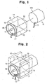
- FIGS. 1 and 4 show a thermally conductive holder 11 in accordance with an embodiment of the present invention.
- a pair of thermally conductive holders 11 are mounted on both end portions 12a of a battery 12 as a heat-generating component, as shown in FIG. 4 .
- the pair of thermally conductive holders 11 holds the battery 12 while protecting the same against external vibration or impact.
- the thermally conductive holder 11 is formed from a thermally conductive composition that contains a silicone rubber and a thermally conductive filler.
- the thermally conductive filler is contained in the range of 40 to 70 percent by volume respective to the total volume of the silicone rubber and the thermally conductive filler.
- the thermally conductive holder 11 is obtained by solidifying the thermally conductive composition into a desired shape.
- the hardness (measured by a type A durometer in conformity with ISO 7619) of the thermally conductive holder 11 is in the range of 20 to 70.
- the thermally conductive holder 11 has rubber elasticity, which allows the elastic deformation thereof for holding the battery 12 as a heat-generating component.
- the thermally conductive holder 11 can be fixed in a device (not shown) to be equipped with the battery 12.
- the thermally conductive holder 11 has a shape corresponding to a hollow rectangular column, as shown in FIGS. 1 and 3 .
- the thermally conductive holder 11 includes inside a receiving portion, namely a generally cylindrical recess 13 for receiving at least a part of the battery 12.
- the recess 13 is defined by the peripheral wall 20 and the distal end wall 21 and has an opening 22 on the proximal end of the thermally conductive holder 11.
- the recess 13 is formed so as to conform to the profile of the cylindrical end portion 12a of the battery 12.
- the thermally conductive holder 11 is mounted on the battery 12 by fitting the end portion 12a of the battery 12 into the recess 13.
- the recess 13 is sized smaller than the profile of the end portion 12a of the battery 12 when the thermally conductive holder 11 is not mounted on the battery 12.
- the inside diameter D1 of the recess 13 is designed to be smaller than the outside diameter D2 of the end portion 12a (the portion to be received in the recess 13) of the battery 12.
- the thermally conductive holder 11 can firmly hold the battery 12 with the outer surface of the end portion 12a closely contacting the inner surface of the recess 13, as shown in FIG. 4 .
- the ratio of D1 to D2 in such a range enables the thermally conductive holder 11 to be easily mounted on the end portion 12a of the battery 12, and secure better contact between the inner surface of the recess 13 and the outer surface of the end portion 12a of the battery 12.
- the outer sides 14 of the thermally conductive holder 11 form heat-conducting interfaces which conduct heat generated from the battery 12 outside, as shown FIGS. 1 and 2 .
- the thermally conductive holder 11 is held between a pair of flat fixing plates 15, as shown by a chain double-dashed line in FIG. 2 , fixed in the inside of the case of any electronic equipment.
- two outer sides 14 in opposite to each other contact the fixing plates 15 to form heat-conducting interfaces therebetween. Accordingly, heat generated from the battery 12 is conducted through the thermally conductive holder 11 via the heat-conducting interfaces to the fixing plates 15, where it is radiated away.
- the fixing plates 15 preferably comprise a metal material because of the excellent heat radiating properties of metal materials.
- Lead wires 17 may be provided on one end of the battery 12, as shown in FIGS 1-4 .
- the lead wires 17 are for connection of a positive electrode and a negative electrode to the outside.
- An aperture 16 may be provided through the distal end wall 21 close proximate to the inner surface of the recess 13. Once the end portion 12a of the battery 12 is fitted into the recess 13, the lead wires 17 are led to the outside of the thermally conductive holder 11 through the aperture 16.
- the thermally conductive holder also includes a cushion member. More particularly, an annular projection 18 and a cylindrical projection 19 positioned in the center of the annular projection 18 are provided as a such cushion member on the outer surface of the distal end wall 21 of the thermally conductive holder 11.
- the annular projection 18 and the cylindrical proj ection 19 may contact the inner surface of a case of any devices equipped with the thermally conductive holder 11 to limit the longitudinal movement of the thermally conductive holder 11.
- These projections 18, 19 also serve to cushion vibration transmitted from the case to the thermally conductive holder 11 due to their rubber elasticity.
- the thermally conductive composition contains a silicone rubber as a matrix so as to provide rubber elasticity to the thermally conductive holder 11.
- the silicone rubber contained in the thermally conductive composition may be a silicone rubber compound in an uncured state.
- Such uncured silicone rubber compounds are commercially available from various manufacturer.
- the silicone rubber compound include millable-type silicone rubber and liquid silicone rubber.
- the millable-type silicone rubber contains highly polymerized (polymerization degree: about 3000 to 10000) organopolysiloxane in a straight chain as its major ingredient.
- the name of "millable-type" silicone rubber comes from the fact that this silicone rubber compound can be processed by using a roll mill.
- a millable-type silicone rubber "SE1120U” is available from Dow Corning Toray Silicone Co., Ltd.
- the liquid silicone rubber contains low polymerized (polymerization degree: about 100 to 2000) organopolysiloxane as its maj or ingredient.
- These silicone rubber compounds typically may further include reinforcing fillers (typically, silica powder) and some additives such as silicone oils.
- the content of the reinforcing filler may be preferably 5 to 50 percent by weight in the compound.
- These silicone rubber compounds are cured to produce solid silicone rubbers using a chemical reaction, such as a crosslinking reaction, condensation reaction or addition reaction, using various curing agents.
- Curing agents include, for example, crosslinking agents and curing catalysts. Such curing agents may be included in the silicone rubber compound used, or may be added separately.
- peroxides such as benzoyl peroxide can be used as a crosslinking agent.
- the thermally conductive composition contains a thermally conductive filler to provide better thermal conductivity to the thermally conductive holder 11.
- the thermally conductive filler is contained in 40 to 70 percent by volume with respect to the total volume of silicone rubber as described above and the thermally conductive filler.
- thermally conductive fillers include magnesium oxide, aluminum oxide, aluminum nitride, boron nitride, silicon carbide and aluminum hydroxide.
- the thermally conductive filler may be electrically insulative to avoid any adverse effects on electrodes or terminals of the heat generating component.
- the thermally conductive composition contains, as a thermally conductive filler, at least magnesium oxide being 5 ⁇ m or less in average particle size.
- Magnesium oxide is characterized by excellent thermal conductivity and relatively low hardness among the above described thermally conductive fillers (magnesium oxide has Mohs hardness of 6). Accordingly, magnesium oxide is unlikely to inhibit the rubber elasticity of the silicone rubber that constitutes the thermally conductive holder 11. More particularly, the use of magnesium oxide being 5 ⁇ m or less in average particle size as a thermally conductive filler can provide heat conductivity and rubber elasticity to the thermally conductive holder 11 in a well-balanced manner.
- the average particle size of magnesium oxide is preferably 4 ⁇ m or less and more preferably 3 ⁇ m or less.
- the smaller average particle size of magnesium oxide is more preferable. However, taking into account its handling ability and ease of producing the thermally conductive holder 11, the average particle size of 0.5 ⁇ m or more is practical. On the other hand, the use of magnesium oxide more than 5 ⁇ m in average particle size makes it difficult to ensure the rubber elasticity of the thermally conductive holder 11.
- the average particle size herein is the value calculated by a laser diffraction method.
- the content of the magnesium oxide of 5 ⁇ m or less in average particle size is 35 to 100 percent by volume, preferably 40 to 100 percent by volume, more preferably 45 to 100 percent by volume and still more preferably 60 to 100 percent by volume with respect to the total volume of the thermally conductive filler. If the content is less than 35 percent by volume, it is impossible to ensure the rubber elasticity of the resultant thermally conductive holder. Setting the content of the magnesium oxide to 5 ⁇ m or less in average particle size in the thermally conductive filler as in the above preferable range can ensure the rubber elasticity of the thermally conductive holder 11 to be obtained and provide excellent thermal conductivity to the same.
- the content of the thermally conductive filler with respect to the total volume of the silicone rubber and the thermally conductive filler is 40 to 70 percent by volume, preferably 45 to 65 percent by volume and more preferably 50 to 60 percent by volume. If the content of the thermally conductive filler is less than 40 percent by volume, it is impossible to provide sufficient thermal conductivity to the thermally conductive holder 11. On the other hand, if the content is more than 70 percent by volume, it is impossible to ensure the rubber elasticity of the resultant thermally conductive holder 11.
- any additional thermally conductive fillers other than magnesium oxide may be added into the thermally conductive composition.
- it is preferable to add aluminum hydroxide as the additional thermally conductive filler because aluminum hydroxide has low hardness, which allows the rubber elasticity of the resultant thermally conductive holder 11 to be ensured.
- the average particle size of the thermally conductive filler to be used is preferably 20 ⁇ m or less. If the average particle size of the thermally conductive filler is 20 ⁇ m or less, the dispersibility of the filler into the silicone rubber can be improved.
- thermally conductive filler Even if the thermally conductive filler is removed due to friction or the like from the surface of the thermally conductive holder 11, such a thermally conductive filler is unlikely to cause malfunction in the electronic components around the thermally conductive holder 11 because of the small particle size thereof.
- the thermally conductive composition may contain additives such as plasticizers, tackifiers, reinforcing agents, colorants, flame retardants and heat-resistance improvers, if necessary.
- the thermally conductive holder 11 is obtained by curing the thermally conductive composition.
- the thermally conductive holder 11 has a hardness of 20 to 70, preferably 25 to 65 and more preferably 30 to 60. This hardness means the value as determined with a type A durometer in conformity a International Standard, ISO 7619, established by International Organization for Standardization. If the hardness is less than 20, the peripheral wall 20 of the thermally conductive holder 11 cannot hold the battery 12 sufficiently. In addition, when fitting the end portion 12a of the battery 12 into the recess 13, the thermally conductive holder 11 can be broken.
- the hardness of the thermally conductive holder 11 is more than 70, the rubber elasticity of the thermally conductive holder 11 is not enough, causing difficulty in the mounting of the thermally conductive holder 11 onto the battery 12. Further, the cushioning effect of the thermally conductive holder 11 is lowered, whereby the thermally conductive holder 11 may be unable to protect the battery 12 from external vibration, impact, and the like.
- the thermal conductivity of the thermally conductive holder 11 is preferably 0.4 W/(m ⁇ K) or more, more preferably 0.6 W/(m ⁇ K) or more andmuch more preferably 0.8 W/(m ⁇ K) or more. If the thermal conductivity is less than 0.4 W/(m ⁇ K), the thermally conductive holder 11 may not conduct heat effectively. This results in accumulated heat in the battery 12, thereby being likely to degrade the performance of the battery 12.
- the higher thermal conductivity of the thermally conductive holder 11 is preferable. However, taking into account the characteristics of silicone rubber and the thermally conductive fillers, the thermal conductivity may be 30 W/(m ⁇ K) or less.
- the process for producing the thermally conductive holder 11 includes a kneading step for preparing a thermally conductive composition; and a molding step for molding the thermally conductive composition.
- a silicone rubber, a thermally conductive filler, a curing agent and additional additives are fed into a kneading machine, and the ingredients are mixed and kneaded to prepare a thermally conductive composition.
- a kneadingmachine a kneader or a roll mill can be used. If necessary, a de-aeration step may be added to remove air bubbles in the resultant thermally conductive composition.
- the amount of the thermally conductive filler mixed is preferably 300 to 700 parts by weight, more preferably 350 to 650 parts by weight, much more preferably 350 to 600 parts by weight and still more preferably 400 to 600 parts by weight per 100 parts by weight, respective to 100 parts by weight of the silicone rubber. If the amount of the thermally conductive filler mixed is less than 300 parts by weight, with respect to 100 parts by weight of silicone rubber, excellent thermal conductivity may not be achieved in the thermally conductive holder 11, whereas if the amount of the thermally conductive filler mixed is more than 700 parts by weight, the moldability of the thermally conductive composition may deteriorate.
- the amount of the magnesium oxide of 5 ⁇ m or less in average particle size is preferably 55 to 100 percent by weight, more preferably 60 to 100 percent by weight and much more preferably 70 to 100 percent by weight in the thermally conductive filler. If this amount is less than 55 percent by weight, the moldability of the thermally conductive composition may deteriorate.
- the thermally conductive composition is fed into a mold, shaped into a desired shape, and solidified by curing the silicone rubber contained in it.
- This molding step allows the thermally conductive holder 11 to be formed integrally.
- the thermally conductive holder 11 formed from the thermally conductive composition as described above can have a hardness of 20 to 70 (measured by type A durometer, in conformity with ISO 7619) and rubber elasticity. Therefore, the recess 13 is easily expanded radially outwardly due to elastic deformation of the peripheral wall 20 utilizing the rubber elasticity, such that the end portion 12a of the battery 12 can be easily fitted into the recess 13. Further, the contact between the inner surface of the peripheral wall 20, which defines the recess 13, and the outer surface of the battery 12 can be improved utilizing the rubber elasticity of the thermally conductive holder 11.
- the thermally conductive holder 11 mounted on the battery 12 may be installed into a device to be equipped with the battery 12.
- the thermally conductive holder 11 mounted on the battery 12 may be held between the two fixing plates 15 fixed in a case of electronic equipment so that the outer sides 14 and the fixing plates 15 are in contact with each other.
- the battery 12 is secured in the inside of the case.
- the thermally conductive holder 11 can be easily held between the two fixing plates 15 utilizing the elastic deformation of the holder 11.
- the thermally conductive holder 11 has a high thermal conductivity because it is formed from the thermally conductive composition described above. Besides, the contact between the inner surface of the peripheral wall 20 of the recess 13 and the outer surface of the battery 12 is secured. Consequently, heat generated from the battery 12 is efficiently conducted to the thermally conductive holder 11. Furthermore, the outer sides 14 of the thermally conductive holder 11 together with the fixing plates 15 form relatively wide heat-conducting interfaces. This allows heat generated from the battery 12 to efficiently conduct to the fixing plates 15 through the thermally conductive holder 11.
- the thermally conductive holder 11 is molded from a thermally conductive composition.
- the thermally conductive composition contains a silicone rubber and a thermally conductive filler in 40 to 70 percent by volume with respect to the total volume of silicone rubber and thermally conductive filler. From 35 to 100 percent by volume of the thermally conductive filler is magnesium oxide being 5 ⁇ m or less in average particle size.
- the hardness of the thermally conductive holder 11 obtained by solidifying the thermally conductive composition is in the range of 20 to 70. In such a configuration, the resultant thermally conductive holder 11 has improved thermal conductivity and ensured rubber elasticity.
- the thermally conductive holder 11 can achieve the effective conduct of heat generated from a heat-generating component such as the battery 12 and easy mounting on the battery 12.
- the thermally conductive holder 11 can reliably hold the battery 12 due to its rubber elasticity. Further, the thermally conductive holder 11 can effectively cushion vibration, impact, and the like from the outside, and thereby protect the battery 12.
- the inside diameter D1 of the recess 13 of the thermally conductive holder 11 is sized smaller than the outside diameter D2 of the end portion 12a of the battery 12 when the thermally conductive holder 11 is not mounted on the battery 12.
- Forming the inner profile of the recess 13 smaller than the outerprofile of the battery 12 further improves the contact between the inner surface of the recess 13 and the outer surface of the battery 12.
- the heat generated from the battery 12 is efficiently conducted to the thermally conductive holder 11. This facilitates the ability of the thermally conductive holder 11 to exert excellent thermal conductivity.
- the thermally conductive holder 11 is constructed so that its outer sides 14 come in face-to-face contact with the fixing plates 15 to form heat-conducting interfaces. Such construction can advantageously ensure a heat-conducting area, which conducts heat, and conduct the heat from the thermally conductive holder 11 to the fixing plates 15 efficiently. Thus, the thermally conductive holder 11 can exert excellent thermal conductivity more effectively.
- the thermal conductivity is preferably 0.4 W/(m ⁇ K) or more.
- the thermally conductive holder 11 can exert more excellent thermal conductivity.
- the thermally conductive composition contains magnesium oxide of 5 ⁇ m or less in average particle size as thermally conductive filler, whereby it can be provided with viscoelastic properties suitable for molding.
- the thermally conductive composition can have excellent moldability.
- thermally conductive holders 11 having complicated shapes can be easily produced from the thermally conductive composition.
- the shape of the recess 13 may be changed to other shapes such as rectangular column according to the shape of the heat-generating component.
- the portion receiving the heat-generating component is not limited to a recess, but may be a cutout that is constructed so as to hold the heat-generating component therebetween.
- the thermally conductive holder 11 may be constructed so that a single thermally conductive holder 11 holds the battery 12 or three or more thermally conductive holders 11 hold the same.
- the aperture 16 need not be provided in the thermally conductive holder 11.
- the outer surface of the distal end wall 21 of the thermally conductive holder 11 may be flat, instead of providing an annular projection 18 and a cylindrical projection 19.
- the thermally conductive holder 11 may be secured in the inside of the case while contacting the outer sides 14 with the inner surface of the case to form a heat conducting interface therebetween, instead of using the fixing plates 15.
- the thermally conductive holder 11 is applicable not only to batteries, but also to other heat-generating components in electronic equipment, such as motors, lamps for liquid crystal displays, and the like.
- the use of a thermally conductive holder 11 in such applications enables heat generated from heating components, such as motors, to be efficiently released, increasing the life of such components.
- the thermally conductive holder 11 may be provided with at least one electrically conductive connector. This can eliminate use of the lead wires 17 for the heat generating components.
- At least one electrically conductive connector may be disposed through the peripheral wall 20 or the distal end wall 21 of the thermally conductive holder 11.
- the thermally conductive holder 11 is placed in the device such that the electrically conductive connectors contact, for example, electrodes of the printed board.
- electrodes of the heat-generating component held by the thermally conductive holder are electrically connected to the electrodes of the printed board through the electrically conductive connectors.
- Examples of such a electrically conductive connector includes a connector comprising metal pin or spring terminals arranged in a case made of a resin, and an electrically conductive rubber connector.
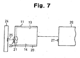
- Figs. 5 to 7 show some embodiments of a thermally conductive holder 11 having such electrically conductive connector (s) .
- the thermally conductive holder 11 shown in Fig.5 is provided with an electrically conductive connector 23a in a generally cylindrical shape.
- the electrically conductive connector 23a is integrally formed with the holder 11 and extends through the peripheral wall 20 in a position so as to face the electrode 27 of the heat-generating component 26 when the holder 11 is mounted on the heat-generating component 26.
- the electrically conductive connector 23a maybemade of any electrically conductive materials.
- the electrically conductive connector 23a at one end preferably projects outward from the peripheral wall 20. This can ensure better contact between the connector 23a and an electrode 25 of a printed board 24.
- the thermally conductive holder 11 is mounted on the heat-generating component 26 with the connector 23a contacting the electrode 27 of the heat-generating component 26. Then, the thermally conductive holder 11 is placed in a device (not shown) such that the connector 23a is compressed by the electrodes 25, 27. Thus, an electrical connection between the electrode 25 of the printed board 24 of the device and the electrode 27 of the heat-generating component 26 held by the thermally conductive holder 11 can be established through the electrically conductive connector 23a.
- a thermally conductive holder 11 is provided with a pair of electrically conductive rubber connectors 23b integrally formed therewith and extending through the distal end wall 21.
- the rubber connectors 23b preferably projects out from the both sides of the peripheral wall 20. This can ensure better contact between the rubber connectors 23b and electrodes 25 of the printed board 24 and the electrodes 27 of the heat-generating component 26.
- the thermally conductive holder 11 is also placed in the device such that the rubber connectors 23b are compressed by a pair of the electrodes 27 provided on the end of the heat-generating component 26 and a corresponding pair of the electrodes 25 of the printed board 24. Thereby, an electrical connection between these electrodes 25 and 27 can be established through the rubber connectors 23b.
- the electrically conductive rubber connector 23b is an elastic member having electrically conductive properties.
- the electrically conductive rubber connector 23b may be made of an elastic material including any electrically conductive media such as metal powders, metal wires or carbon powders. It is preferable that the elastic material be a silicone rubber.
- a thermally conductive holder 11 is provided with an electrically conductive connector 23c disposed through the distal end wall 21.
- the electrically conductive connector 23c comprises a metal spring terminal arranged in a resin case.
- the electrically conductive connector 23c preferably projects out from both sides of the peripheral wall 20. This can ensure better contact between the connector 23c and the electrode 25 of the printed board 24 and the electrode 27 of the heat-generating component 26.
- This thermally conductive holder 11 is also placed in a device such that the connector 23c is compressed by the electrodes 25 of the printed board 24 and the electrode27 of the heat-generating component 26. Thereby, an electrical connection between these electrodes 25 and 27 can be established through the electrically conductive connector 23c.
- the electrically conductive connector in each embodiment may be integrated with the thermally conductive holder 11. Such integration may be achieved by embedding the electrically conductive connectors, which are separately formed, in the peripheral wall 20 or the distal end wall 21 of the thermally conductive holder 11 or by integrally molding the connectors with the thermally conductive holder using a mold.
- Millable silicone rubber (“SE1120U” manufactured by Dow Corning Toray Silicone Co., Ltd; specific gravity of 1.00) as a silicone rubber, magnesium oxide (true specific gravity of 3. 58) as a thermally conductive filler, and optionally, aluminum hydroxide (true specific gravity 2.20, average particle size 1.1 ⁇ m) were mixed in the mixing ratios shown in Table 1 and Table 2.
- a peroxide crosslinking agent as a crosslinking agent.
- the mixture was mixed and kneaded with a roll mill, until the ingredients were dispersed uniformly, to yield a thermally conductive composition.
- (A) the ratio of the thermally conductive filler with respect to the total volume of the silicone rubber and the thermally conductive filler [percent by volume] (hereinafter, referred to as ratio of (A)) and (B) the ratio of the magnesium oxide of 5 ⁇ m or less in average particle size respective to the total volume of the thermally conductive filler [percent by volume] (hereinafter, referred to as ratio of (B)) are shown in Table 1 and Table 2.
- thermally conductive holders 11 were obtained.
- the ratio of the inside diameter D1 of the recess 13 to the outside diameter D2 of the battery 12 was 90 percent.
- Each of the resultant thermally conductive holders 11 was evaluated as to moldability based on three factors: mold releasability, surface conditions and dimensional stability. The results were classified into 3 grades as shown below. The results are shown in Table 1 and Table 2.
- each thermally conductive holder 11 was determined with a type A durometer in accordance with ISO 7619. To determine the thermal conductivity of the thermally conductive holders 11, test pieces of 2 mm thick sheets were prepared by molding each of the thermally conductive compositions obtained in the examples and the comparative examples using a mold heat at 170°C for 10 minutes. The thermal conductivity of each test piece was determined with the Quick Thermal Conductivity Meter (Model QTM-500, manufactured by Kyoto Electronics Manufacturing Co., Ltd.,). The measurements of the hardness and the thermal conductivity are shown in Table 1 and Table 2.
- the moldability of the thermally conductive compositions of examples 1 to 5 was GOOD.
- high thermal conductivity of 0.4 W/(m ⁇ K) or more was achieved.
- the thermally conductive holder 11 of each example had GOOD mounting workability without any breakage when mounted on the battery 12. This may be because the thermally conductive holder 11 of each example was formed of the thermally conductive composition in which the ratio of (A) was 40 to 70 percent by volume and the ratio of (B) was 35 to 100 percent by volume, and thus the rubber elasticity of the thermally conductive holder 11 was ensured and sufficient extension and tear strength of the same could be obtained.
- the hardness of the thermally conductive holder 11 of each example was in the range of 20 to 70. Probably GOOD mounting workability was obtained due to the mutual relation among the extension, tear strength and hardness of the thermally conductive holder 11.
- thermally conductive holders 11 of comparative examples 1 and 2 mounting workability was POOR or BAD.
- These thermally conductive holders 11 contained magnesium oxide greater than 5 ⁇ m in average particle size as a thermally conductive filler. This probably made it impossible to ensure sufficient rubber elasticity of the thermally conductive holders 11 and achieve sufficient extension and tear strength of the same.
- the low thermal conductivity of the thermally conductive holder 11 is attributed to the fact that the ratio of (A) was less than 40 percent by volume.
- the POOR mounting workability of the thermally conductive holder 11 is attributed to the fact that its hardness was greater than 70.
- the POOR moldability and mounting workability of the thermally conductive holder 11 is attributed to the fact that the ratio of (B) was less than 35 percent by volume.
Landscapes
- Chemical & Material Sciences (AREA)
- Chemical Kinetics & Catalysis (AREA)
- Electrochemistry (AREA)
- General Chemical & Material Sciences (AREA)
- Health & Medical Sciences (AREA)
- Medicinal Chemistry (AREA)
- Polymers & Plastics (AREA)
- Organic Chemistry (AREA)
- Compositions Of Macromolecular Compounds (AREA)
- Secondary Cells (AREA)
- Battery Mounting, Suspending (AREA)
Description
- The present invention relates to a thermally conductive holder for holding a heat-generating component such as a battery.
- In recent years, there have been demands in the field of electronic equipment for realizing not only its miniaturization and better performance, but also its availability for a longer period of time. With such demands, in the field of batteries mounted in electronic equipment, efforts have been directed toward their miniaturization as well as an increase in their capacity. As a result, the power consumption from the batteries has been increased, causing a larger amount of heat to be generated from the batteries.
- Traditionally, to protect such batteries, a cushion member formed in a sheet has been sometimes provided around them.
Japanese Patent Laid-Open No. 11-273643 - Recently, there has also been proposed a holder, as a thermally conductive cushion member, which is formed into a shape conforming to the profile of a battery and mounted on the battery to be used.
- A rubber material is used as a base material for the holder above described, because it facilitates easymounting of the holder onto a heat-generating component such as battery and excels in cushioning action. It is required for improving thermal conductivity of the holder to incorporate a large amount of thermally conductive filler into the rubber material.
- However, inclusion of the large amount of thermally conductive filler into the rubber material can decrease the elasticity of the rubber of the holder to be obtained, which results in difficulty in mounting the holder on a heat-generating component.
- Document
EP 1014421 discloses a thermally conductive holder having a composition including a silicon rubber and a thermally conductive filler. - To deal with the above-mentioned disadvantages, an objective of the present invention is to provide a thermally conductive holder that has excellent thermal conductivity, and is easy to mount on a heat-generating component.
- The present invention provides a thermally conductive holder formed from a thermally conductive composition for holding a heat-generating component. The thermally conductive composition includes a silicone rubber; and a thermally conductive filler in a range of 40 to 70 percent by volume respective to total volume of the silicone rubber and the thermally conductive filler. From 35 to 100 percent by volume of the thermally conductive filler is composed of magnesium oxide of 5 µm or less in average particle size. The thermally conductive holder (11) has a hardness in a range from 20 to 70 as measured by a Type A durometer in conformity with ISO 7619.
- Other aspects and advantages of the invention will become apparent from the following description, taken in conjunction with the accompanying drawings, illustrating by way of example the principles of the invention.
- The invention, together with objects and advantages thereof, may best be understood by reference to the following description of the presently preferred embodiments together with the accompanying drawings in which:
-
FIG. 1 is a perspective view showing a thermally conductive holder in accordance with one embodiment of the present invention and a battery; -
FIG. 2 is a perspective view of the thermally conductive holder mounted on a battery; -
FIG. 3 is a side view showing the thermally conductive holder and a battery; -
FIG. 4 is a side view of the thermally conductive holder mounted on a battery; -
Fig. 5 is a side view showing a thermally conductive holder in accordance with another embodiment of the present invention; -
Fig. 6 is a side view showing a thermally conductive holder in accordance with yet another embodiment of the present invention; -
Fig. 7 is a side view showing a thermally conductive holder in accordance with still another embodiment of the present invention; - In the following paragraphs, an embodiment of the present invention will be described in detail with reference to the accompanying drawings.
-
FIGS. 1 and4 show a thermallyconductive holder 11 in accordance with an embodiment of the present invention. In this embodiment, a pair of thermallyconductive holders 11 are mounted on bothend portions 12a of abattery 12 as a heat-generating component, as shown inFIG. 4 . The pair of thermallyconductive holders 11 holds thebattery 12 while protecting the same against external vibration or impact. The thermallyconductive holder 11 is formed from a thermally conductive composition that contains a silicone rubber and a thermally conductive filler. In the thermally conductive composition, the thermally conductive filler is contained in the range of 40 to 70 percent by volume respective to the total volume of the silicone rubber and the thermally conductive filler. From 35 to 100 percent by volume of the thermally conductive filler is composed of magnesium oxide being 5 µm or less on average in particle size. The thermallyconductive holder 11 is obtained by solidifying the thermally conductive composition into a desired shape. The hardness (measured by a type A durometer in conformity with ISO 7619) of the thermallyconductive holder 11 is in the range of 20 to 70. The thermallyconductive holder 11 has rubber elasticity, which allows the elastic deformation thereof for holding thebattery 12 as a heat-generating component. For use, the thermallyconductive holder 11 can be fixed in a device (not shown) to be equipped with thebattery 12. - In this embodiment, the thermally
conductive holder 11 has a shape corresponding to a hollow rectangular column, as shown inFIGS. 1 and3 . The thermallyconductive holder 11 includes inside a receiving portion, namely a generallycylindrical recess 13 for receiving at least a part of thebattery 12. Therecess 13 is defined by theperipheral wall 20 and thedistal end wall 21 and has an opening 22 on the proximal end of the thermallyconductive holder 11. Therecess 13 is formed so as to conform to the profile of thecylindrical end portion 12a of thebattery 12. The thermallyconductive holder 11 is mounted on thebattery 12 by fitting theend portion 12a of thebattery 12 into therecess 13. - As shown in
FIG. 3 , therecess 13 is sized smaller than the profile of theend portion 12a of thebattery 12 when the thermallyconductive holder 11 is not mounted on thebattery 12. Specifically, the inside diameter D1 of therecess 13 is designed to be smaller than the outside diameter D2 of theend portion 12a (the portion to be received in the recess 13) of thebattery 12. Once theend portion 12a of thebattery 12 is inserted in therecess 13, the rubber elasticity of theholder 11 allows theperipheral wall 20 to be elastically deformed so that therecess 13 is expanded radially outwardly. Accordingly, the thermallyconductive holder 11 can firmly hold thebattery 12 with the outer surface of theend portion 12a closely contacting the inner surface of therecess 13, as shown inFIG. 4 . The ratio of the inside diameter D1 to the outside diameter D2 (= D1/D2 × 100) is preferably in the range of 85 to 95 percent. The ratio of D1 to D2 in such a range enables the thermallyconductive holder 11 to be easily mounted on theend portion 12a of thebattery 12, and secure better contact between the inner surface of therecess 13 and the outer surface of theend portion 12a of thebattery 12. - The
outer sides 14 of the thermallyconductive holder 11 form heat-conducting interfaces which conduct heat generated from thebattery 12 outside, as shownFIGS. 1 and 2 . For example, the thermallyconductive holder 11 is held between a pair offlat fixing plates 15, as shown by a chain double-dashed line inFIG. 2 , fixed in the inside of the case of any electronic equipment. In this arrangement, twoouter sides 14 in opposite to each other, contact thefixing plates 15 to form heat-conducting interfaces therebetween. Accordingly, heat generated from thebattery 12 is conducted through the thermallyconductive holder 11 via the heat-conducting interfaces to thefixing plates 15, where it is radiated away. Thefixing plates 15 preferably comprise a metal material because of the excellent heat radiating properties of metal materials. -
Lead wires 17 may be provided on one end of thebattery 12, as shown inFIGS 1-4 . Thelead wires 17 are for connection of a positive electrode and a negative electrode to the outside. Anaperture 16 may be provided through thedistal end wall 21 close proximate to the inner surface of therecess 13. Once theend portion 12a of thebattery 12 is fitted into therecess 13, thelead wires 17 are led to the outside of the thermallyconductive holder 11 through theaperture 16. - The thermally conductive holder also includes a cushion member. More particularly, an
annular projection 18 and acylindrical projection 19 positioned in the center of theannular projection 18 are provided as a such cushion member on the outer surface of thedistal end wall 21 of the thermallyconductive holder 11. Theannular projection 18 and thecylindrical proj ection 19 may contact the inner surface of a case of any devices equipped with the thermallyconductive holder 11 to limit the longitudinal movement of the thermallyconductive holder 11. Theseprojections conductive holder 11 due to their rubber elasticity. - The thermally conductive composition contains a silicone rubber as a matrix so as to provide rubber elasticity to the thermally
conductive holder 11. In practical, the silicone rubber contained in the thermally conductive composition may be a silicone rubber compound in an uncured state. Such uncured silicone rubber compounds are commercially available from various manufacturer. Examples of the silicone rubber compound include millable-type silicone rubber and liquid silicone rubber. The millable-type silicone rubber contains highly polymerized (polymerization degree: about 3000 to 10000) organopolysiloxane in a straight chain as its major ingredient. The name of "millable-type" silicone rubber comes from the fact that this silicone rubber compound can be processed by using a roll mill. For example, a millable-type silicone rubber "SE1120U" is available from Dow Corning Toray Silicone Co., Ltd. The liquid silicone rubber contains low polymerized (polymerization degree: about 100 to 2000) organopolysiloxane as its maj or ingredient. These silicone rubber compounds typically may further include reinforcing fillers (typically, silica powder) and some additives such as silicone oils. In the millable-type silicone rubber to be used for the present invention, the content of the reinforcing filler may be preferably 5 to 50 percent by weight in the compound. These silicone rubber compounds are cured to produce solid silicone rubbers using a chemical reaction, such as a crosslinking reaction, condensation reaction or addition reaction, using various curing agents. Curing agents include, for example, crosslinking agents and curing catalysts. Such curing agents may be included in the silicone rubber compound used, or may be added separately. For the millable silicone rubber, for example, peroxides such as benzoyl peroxide can be used as a crosslinking agent. - The thermally conductive composition contains a thermally conductive filler to provide better thermal conductivity to the thermally
conductive holder 11. In the thermally conductive composition, the thermally conductive filler is contained in 40 to 70 percent by volume with respect to the total volume of silicone rubber as described above and the thermally conductive filler. Examples of thermally conductive fillers include magnesium oxide, aluminum oxide, aluminum nitride, boron nitride, silicon carbide and aluminum hydroxide. Preferably, the thermally conductive filler may be electrically insulative to avoid any adverse effects on electrodes or terminals of the heat generating component. - The thermally conductive composition contains, as a thermally conductive filler, at least magnesium oxide being 5 µm or less in average particle size. Magnesium oxide is characterized by excellent thermal conductivity and relatively low hardness among the above described thermally conductive fillers (magnesium oxide has Mohs hardness of 6). Accordingly, magnesium oxide is unlikely to inhibit the rubber elasticity of the silicone rubber that constitutes the thermally
conductive holder 11. More particularly, the use of magnesium oxide being 5 µm or less in average particle size as a thermally conductive filler can provide heat conductivity and rubber elasticity to the thermallyconductive holder 11 in a well-balanced manner. The average particle size of magnesium oxide is preferably 4 µm or less and more preferably 3 µm or less. The smaller average particle size of magnesium oxide is more preferable. However, taking into account its handling ability and ease of producing the thermallyconductive holder 11, the average particle size of 0.5 µm or more is practical. On the other hand, the use of magnesium oxide more than 5 µm in average particle size makes it difficult to ensure the rubber elasticity of the thermallyconductive holder 11. The average particle size herein is the value calculated by a laser diffraction method. - The content of the magnesium oxide of 5 µm or less in average particle size is 35 to 100 percent by volume, preferably 40 to 100 percent by volume, more preferably 45 to 100 percent by volume and still more preferably 60 to 100 percent by volume with respect to the total volume of the thermally conductive filler. If the content is less than 35 percent by volume, it is impossible to ensure the rubber elasticity of the resultant thermally conductive holder. Setting the content of the magnesium oxide to 5 µm or less in average particle size in the thermally conductive filler as in the above preferable range can ensure the rubber elasticity of the thermally
conductive holder 11 to be obtained and provide excellent thermal conductivity to the same. - In the thermally conductive composition, the content of the thermally conductive filler with respect to the total volume of the silicone rubber and the thermally conductive filler is 40 to 70 percent by volume, preferably 45 to 65 percent by volume and more preferably 50 to 60 percent by volume. If the content of the thermally conductive filler is less than 40 percent by volume, it is impossible to provide sufficient thermal conductivity to the thermally
conductive holder 11. On the other hand, if the content is more than 70 percent by volume, it is impossible to ensure the rubber elasticity of the resultant thermallyconductive holder 11. - Any additional thermally conductive fillers other than magnesium oxide may be added into the thermally conductive composition. In this case, it is preferable to add aluminum hydroxide as the additional thermally conductive filler, because aluminum hydroxide has low hardness, which allows the rubber elasticity of the resultant thermally
conductive holder 11 to be ensured. Further, when using a thermally conductive filler other than magnesium oxide of 5 µm or less in average particle size, the average particle size of the thermally conductive filler to be used is preferably 20 µm or less. If the average particle size of the thermally conductive filler is 20 µm or less, the dispersibility of the filler into the silicone rubber can be improved. Even if the thermally conductive filler is removed due to friction or the like from the surface of the thermallyconductive holder 11, such a thermally conductive filler is unlikely to cause malfunction in the electronic components around the thermallyconductive holder 11 because of the small particle size thereof. - The thermally conductive composition may contain additives such as plasticizers, tackifiers, reinforcing agents, colorants, flame retardants and heat-resistance improvers, if necessary.
- The thermally
conductive holder 11 is obtained by curing the thermally conductive composition. The thermallyconductive holder 11 has a hardness of 20 to 70, preferably 25 to 65 and more preferably 30 to 60. This hardness means the value as determined with a type A durometer in conformity a International Standard, ISO 7619, established by International Organization for Standardization. If the hardness is less than 20, theperipheral wall 20 of the thermallyconductive holder 11 cannot hold thebattery 12 sufficiently. In addition, when fitting theend portion 12a of thebattery 12 into therecess 13, the thermallyconductive holder 11 can be broken. On the other hand, if the hardness of the thermallyconductive holder 11 is more than 70, the rubber elasticity of the thermallyconductive holder 11 is not enough, causing difficulty in the mounting of the thermallyconductive holder 11 onto thebattery 12. Further, the cushioning effect of the thermallyconductive holder 11 is lowered, whereby the thermallyconductive holder 11 may be unable to protect thebattery 12 from external vibration, impact, and the like. - The thermal conductivity of the thermally
conductive holder 11 is preferably 0.4 W/(m·K) or more, more preferably 0.6 W/(m·K) or more andmuch more preferably 0.8 W/(m·K) or more. If the thermal conductivity is less than 0.4 W/(m·K), the thermallyconductive holder 11 may not conduct heat effectively. This results in accumulated heat in thebattery 12, thereby being likely to degrade the performance of thebattery 12. The higher thermal conductivity of the thermallyconductive holder 11 is preferable. However, taking into account the characteristics of silicone rubber and the thermally conductive fillers, the thermal conductivity may be 30 W/(m·K) or less. - In the following, a process for producing the thermally
conductive holder 11 will be described. - The process for producing the thermally
conductive holder 11 includes a kneading step for preparing a thermally conductive composition; and a molding step for molding the thermally conductive composition. - In the kneading step, a silicone rubber, a thermally conductive filler, a curing agent and additional additives are fed into a kneading machine, and the ingredients are mixed and kneaded to prepare a thermally conductive composition. As the kneadingmachine, a kneader or a roll mill can be used. If necessary, a de-aeration step may be added to remove air bubbles in the resultant thermally conductive composition. In the thermally conductive composition, the amount of the thermally conductive filler mixed is preferably 300 to 700 parts by weight, more preferably 350 to 650 parts by weight, much more preferably 350 to 600 parts by weight and still more preferably 400 to 600 parts by weight per 100 parts by weight, respective to 100 parts by weight of the silicone rubber. If the amount of the thermally conductive filler mixed is less than 300 parts by weight, with respect to 100 parts by weight of silicone rubber, excellent thermal conductivity may not be achieved in the thermally
conductive holder 11, whereas if the amount of the thermally conductive filler mixed is more than 700 parts by weight, the moldability of the thermally conductive composition may deteriorate. The amount of the magnesium oxide of 5 µm or less in average particle size is preferably 55 to 100 percent by weight, more preferably 60 to 100 percent by weight and much more preferably 70 to 100 percent by weight in the thermally conductive filler. If this amount is less than 55 percent by weight, the moldability of the thermally conductive composition may deteriorate. - In the molding step, the thermally conductive composition is fed into a mold, shaped into a desired shape, and solidified by curing the silicone rubber contained in it. This molding step allows the thermally
conductive holder 11 to be formed integrally. When solidifying the thermally conductive composition in this molding step, it is preferable to heat the mold to appropriate temperatures depending on the types of the silicone rubber and the curing agent used. - To mount the thermally
conductive holder 11 to thebattery 12, theend portion 12a of thebattery 12 is fitted into therecess 13. The thermallyconductive holder 11 formed from the thermally conductive composition as described above can have a hardness of 20 to 70 (measured by type A durometer, in conformity with ISO 7619) and rubber elasticity. Therefore, therecess 13 is easily expanded radially outwardly due to elastic deformation of theperipheral wall 20 utilizing the rubber elasticity, such that theend portion 12a of thebattery 12 can be easily fitted into therecess 13. Further, the contact between the inner surface of theperipheral wall 20, which defines therecess 13, and the outer surface of thebattery 12 can be improved utilizing the rubber elasticity of the thermallyconductive holder 11. - Then, the thermally
conductive holder 11 mounted on thebattery 12 may be installed into a device to be equipped with thebattery 12. For example, the thermallyconductive holder 11 mounted on thebattery 12 may be held between the two fixingplates 15 fixed in a case of electronic equipment so that theouter sides 14 and the fixingplates 15 are in contact with each other. Thus, thebattery 12 is secured in the inside of the case. In this case, the thermallyconductive holder 11 can be easily held between the two fixingplates 15 utilizing the elastic deformation of theholder 11. - Once electronic equipment equipped with the
battery 12 held by the thermallyconductive holder 11 is used, heat generated from thebattery 12 is conducted to the thermallyconductive holder 11. The thermallyconductive holder 11 has a high thermal conductivity because it is formed from the thermally conductive composition described above. Besides, the contact between the inner surface of theperipheral wall 20 of therecess 13 and the outer surface of thebattery 12 is secured. Consequently, heat generated from thebattery 12 is efficiently conducted to the thermallyconductive holder 11. Furthermore, theouter sides 14 of the thermallyconductive holder 11 together with the fixingplates 15 form relatively wide heat-conducting interfaces. This allows heat generated from thebattery 12 to efficiently conduct to the fixingplates 15 through the thermallyconductive holder 11. - Advantages achieved by this embodiment will be described as below.
- In the embodiment described above, the thermally
conductive holder 11 is molded from a thermally conductive composition. The thermally conductive composition contains a silicone rubber and a thermally conductive filler in 40 to 70 percent by volume with respect to the total volume of silicone rubber and thermally conductive filler. From 35 to 100 percent by volume of the thermally conductive filler is magnesium oxide being 5 µm or less in average particle size. The hardness of the thermallyconductive holder 11 obtained by solidifying the thermally conductive composition is in the range of 20 to 70. In such a configuration, the resultant thermallyconductive holder 11 has improved thermal conductivity and ensured rubber elasticity. As a result, the thermallyconductive holder 11 can achieve the effective conduct of heat generated from a heat-generating component such as thebattery 12 and easy mounting on thebattery 12. The thermallyconductive holder 11 can reliably hold thebattery 12 due to its rubber elasticity. Further, the thermallyconductive holder 11 can effectively cushion vibration, impact, and the like from the outside, and thereby protect thebattery 12. - In the embodiment, the inside diameter D1 of the
recess 13 of the thermallyconductive holder 11 is sized smaller than the outside diameter D2 of theend portion 12a of thebattery 12 when the thermallyconductive holder 11 is not mounted on thebattery 12. Forming the inner profile of therecess 13 smaller than the outerprofile of thebattery 12 further improves the contact between the inner surface of therecess 13 and the outer surface of thebattery 12. Thus, the heat generated from thebattery 12 is efficiently conducted to the thermallyconductive holder 11. This facilitates the ability of the thermallyconductive holder 11 to exert excellent thermal conductivity. - In the embodiment, the thermally
conductive holder 11 is constructed so that itsouter sides 14 come in face-to-face contact with the fixingplates 15 to form heat-conducting interfaces. Such construction can advantageously ensure a heat-conducting area, which conducts heat, and conduct the heat from the thermallyconductive holder 11 to the fixingplates 15 efficiently. Thus, the thermallyconductive holder 11 can exert excellent thermal conductivity more effectively. - In a thermally
conductive holder 11 in accordance with this embodiment, the thermal conductivity is preferably 0.4 W/(m·K) or more. In this case, the thermallyconductive holder 11 can exert more excellent thermal conductivity. - In the embodiment, the thermally conductive composition contains magnesium oxide of 5 µm or less in average particle size as thermally conductive filler, whereby it can be provided with viscoelastic properties suitable for molding. Thus the thermally conductive composition can have excellent moldability. As a result, thermally
conductive holders 11 having complicated shapes can be easily produced from the thermally conductive composition. - The shape of the
recess 13 may be changed to other shapes such as rectangular column according to the shape of the heat-generating component. In the thermallyconductive holder 11, the portion receiving the heat-generating component is not limited to a recess, but may be a cutout that is constructed so as to hold the heat-generating component therebetween. - The thermally
conductive holder 11 may be constructed so that a single thermallyconductive holder 11 holds thebattery 12 or three or more thermallyconductive holders 11 hold the same. When thelead wires 17 need not be led to the outside via the thermallyconductive holder 11, theaperture 16 need not be provided in the thermallyconductive holder 11. - The outer surface of the
distal end wall 21 of the thermallyconductive holder 11 may be flat, instead of providing anannular projection 18 and acylindrical projection 19. - The thermally
conductive holder 11 may be secured in the inside of the case while contacting theouter sides 14 with the inner surface of the case to form a heat conducting interface therebetween, instead of using the fixingplates 15. - The thermally
conductive holder 11 is applicable not only to batteries, but also to other heat-generating components in electronic equipment, such as motors, lamps for liquid crystal displays, and the like. The use of a thermallyconductive holder 11 in such applications enables heat generated from heating components, such as motors, to be efficiently released, increasing the life of such components. - In an application where a heat-generating component requires electrical connection through the thermally
conductive holder 11 with another member, such as a printed board, of a device to be equipped with theholder 11 and the heat-generating component, the thermallyconductive holder 11 may be provided with at least one electrically conductive connector. This can eliminate use of thelead wires 17 for the heat generating components. - More particularly, at least one electrically conductive connector may be disposed through the
peripheral wall 20 or thedistal end wall 21 of the thermallyconductive holder 11. The thermallyconductive holder 11 is placed in the device such that the electrically conductive connectors contact, for example, electrodes of the printed board. As a result, electrodes of the heat-generating component held by the thermally conductive holder are electrically connected to the electrodes of the printed board through the electrically conductive connectors. - Examples of such a electrically conductive connector includes a connector comprising metal pin or spring terminals arranged in a case made of a resin, and an electrically conductive rubber connector.
-
Figs. 5 to 7 show some embodiments of a thermallyconductive holder 11 having such electrically conductive connector (s) . The thermallyconductive holder 11 shown inFig.5 is provided with an electricallyconductive connector 23a in a generally cylindrical shape. The electricallyconductive connector 23a is integrally formed with theholder 11 and extends through theperipheral wall 20 in a position so as to face theelectrode 27 of the heat-generatingcomponent 26 when theholder 11 is mounted on the heat-generatingcomponent 26. The electrically conductive connector 23amaybemade of any electrically conductive materials. The electricallyconductive connector 23a at one end preferably projects outward from theperipheral wall 20. This can ensure better contact between theconnector 23a and anelectrode 25 of a printedboard 24. The thermallyconductive holder 11 is mounted on the heat-generatingcomponent 26 with theconnector 23a contacting theelectrode 27 of the heat-generatingcomponent 26. Then, the thermallyconductive holder 11 is placed in a device (not shown) such that theconnector 23a is compressed by theelectrodes electrode 25 of the printedboard 24 of the device and theelectrode 27 of the heat-generatingcomponent 26 held by the thermallyconductive holder 11 can be established through the electricallyconductive connector 23a. - In another embodiment shown in
Fig. 6 , a thermallyconductive holder 11 is provided with a pair of electricallyconductive rubber connectors 23b integrally formed therewith and extending through thedistal end wall 21. Therubber connectors 23b preferably projects out from the both sides of theperipheral wall 20. This can ensure better contact between therubber connectors 23b andelectrodes 25 of the printedboard 24 and theelectrodes 27 of the heat-generatingcomponent 26. The thermallyconductive holder 11 is also placed in the device such that therubber connectors 23b are compressed by a pair of theelectrodes 27 provided on the end of the heat-generatingcomponent 26 and a corresponding pair of theelectrodes 25 of the printedboard 24. Thereby, an electrical connection between theseelectrodes rubber connectors 23b. The electricallyconductive rubber connector 23b is an elastic member having electrically conductive properties. The electricallyconductive rubber connector 23b may be made of an elastic material including any electrically conductive media such as metal powders, metal wires or carbon powders. It is preferable that the elastic material be a silicone rubber. - In another embodiment shown in
Fig. 7 , a thermallyconductive holder 11 is provided with an electrically conductive connector 23c disposed through thedistal end wall 21. The electrically conductive connector 23c comprises a metal spring terminal arranged in a resin case. The electrically conductive connector 23c preferably projects out from both sides of theperipheral wall 20. This can ensure better contact between the connector 23c and theelectrode 25 of the printedboard 24 and theelectrode 27 of the heat-generatingcomponent 26. This thermallyconductive holder 11 is also placed in a device such that the connector 23c is compressed by theelectrodes 25 of the printedboard 24 and the electrode27 of the heat-generatingcomponent 26. Thereby, an electrical connection between theseelectrodes - The electrically conductive connector in each embodiment may be integrated with the thermally
conductive holder 11. Such integration may be achieved by embedding the electrically conductive connectors, which are separately formed, in theperipheral wall 20 or thedistal end wall 21 of the thermallyconductive holder 11 or by integrally molding the connectors with the thermally conductive holder using a mold. - The above described embodiment will be described in further detail with several examples and comparative examples.
- Millable silicone rubber ("SE1120U" manufactured by Dow Corning Toray Silicone Co., Ltd; specific gravity of 1.00) as a silicone rubber, magnesium oxide (true specific gravity of 3. 58) as a thermally conductive filler, and optionally, aluminum hydroxide (true specific gravity 2.20, average particle size 1.1 µm) were mixed in the mixing ratios shown in Table 1 and Table 2. To the mixture was added a peroxide crosslinking agent as a crosslinking agent. Then the mixture was mixed and kneaded with a roll mill, until the ingredients were dispersed uniformly, to yield a thermally conductive composition.
- For the thermally conductive compositions of examples 1 to 5 and comparative examples 1 to 5, (A) the ratio of the thermally conductive filler with respect to the total volume of the silicone rubber and the thermally conductive filler [percent by volume] (hereinafter, referred to as ratio of (A)) and (B) the ratio of the magnesium oxide of 5 µm or less in average particle size respective to the total volume of the thermally conductive filler [percent by volume] (hereinafter, referred to as ratio of (B)) are shown in Table 1 and Table 2.
- Each of the resultant thermally conductive compositions was fed into a mold and kept at 175°C for 10 minutes, thereby being molded into a desired shape. Thus thermally
conductive holders 11 were obtained. In the resultant thermallyconductive holders 11, the ratio of the inside diameter D1 of therecess 13 to the outside diameter D2 of thebattery 12 was 90 percent. Each of the resultant thermallyconductive holders 11 was evaluated as to moldability based on three factors: mold releasability, surface conditions and dimensional stability. The results were classified into 3 grades as shown below. The results are shown in Table 1 and Table 2. - Mold releasability, surface conditions and dimensional stability are all satisfactory: GOOD
- Any one of mold releasability, surface conditions and dimensional stability is not satisfactory: POOR
- None of mold releasability, surface conditions and dimensional stability are satisfactory: BAD
- The hardness of each thermally
conductive holder 11 was determined with a type A durometer in accordance with ISO 7619. To determine the thermal conductivity of the thermallyconductive holders 11, test pieces of 2 mm thick sheets were prepared by molding each of the thermally conductive compositions obtained in the examples and the comparative examples using a mold heat at 170°C for 10 minutes. The thermal conductivity of each test piece was determined with the Quick Thermal Conductivity Meter (Model QTM-500, manufactured by Kyoto Electronics Manufacturing Co., Ltd.,). The measurements of the hardness and the thermal conductivity are shown in Table 1 and Table 2. - The workability of each thermally
conductive holder 11 when it was mounted on thebattery 12 was evaluated according to the following classifications. - The thermally
conductive holder 11 showed excellent rubber elasticity, no malfunction such as breakage was caused in theholder 11, and theholder 11 was easy to mount on the battery 12: GOOD - The rubber elasticity of the thermally
conductive holder 11 was not enough and the thermallyconductive holder 11 was a little difficult to mount on the battery 12: POOR - Damage such as cracking occurred in the thermally
conductive holder 11 and the thermallyconductive holder 11 was difficult to mount on the battery 12: BAD - The results of this evaluation are also shown in Table 1 and Table 2.
Table 1 Examples 1 2 3 4 5 Composition (parts by weight) Millable silicone rubber 100 100 100 100 100 Magnesium oxide (Ave.p.s.: 3 µm) 300 400 600 400 200 Aluminum hydroxide 100 - - 150 150 Crosslinking agent 0.8 0.8 0.8 0.8 0.8 Ratio of (A) [percent by volume] 56 56 63 64 55 Ratio of (B) [percent by volume] 65 100 100 62 45 Moldability GOOD GOOD GOOD GOOD GOOD Hardness (Type A durometer, ISO 7619) 46 36 47 58 52 Thermal conductivity [W/(m·k)] 0.8 0.9 1.7 1.5 1.4 Workability when mounted GOOD GOOD GOOD GOOD GOOD Table 2 Comparative Examples 1 2 3 4 5 Composition (parts by weight) Millable silicone rubber 100 100 100 100 100 Magnesium oxides Ave.p.s.: 3 µm - - 200 600 150 Ave.p.s.: 6 µm 300 - - - - Ave.p,s.: 13 µm - 300 - - - Aluminum hydroxide 100 100 - 150 250 Crosslinking agent 0.8 0.8 0.8 0.8 0.8 Ratio of (A) [percent by volume] 56 56 36 70 61 Ratio of (B) [percent by volume] - - 100 71 27 Moldability POOR BAD GOOD POOR POOR Hardness (Type A durometer, ISO 7619) 45 42 28 71 31 Thermal conductivity [W/(m·k)] 0.7 0.8 0.2 2.1 0.5 Workability when mounted POOR BAD POOR BAD POOR - As is apparent from the results shown in Table 1, the moldability of the thermally conductive compositions of examples 1 to 5 was GOOD. In each example, high thermal conductivity of 0.4 W/(m·K) or more was achieved. Further, the thermally
conductive holder 11 of each example had GOOD mounting workability without any breakage when mounted on thebattery 12. This may be because the thermallyconductive holder 11 of each example was formed of the thermally conductive composition in which the ratio of (A) was 40 to 70 percent by volume and the ratio of (B) was 35 to 100 percent by volume, and thus the rubber elasticity of the thermallyconductive holder 11 was ensured and sufficient extension and tear strength of the same could be obtained. The hardness of the thermallyconductive holder 11 of each example was in the range of 20 to 70. Probably GOOD mounting workability was obtained due to the mutual relation among the extension, tear strength and hardness of the thermallyconductive holder 11. - In contrast, as is apparent from the results shown in Table 2, in the thermally
conductive holders 11 of comparative examples 1 and 2, mounting workability was POOR or BAD. These thermallyconductive holders 11 contained magnesium oxide greater than 5 µm in average particle size as a thermally conductive filler. This probably made it impossible to ensure sufficient rubber elasticity of the thermallyconductive holders 11 and achieve sufficient extension and tear strength of the same. In comparative example 3, the low thermal conductivity of the thermallyconductive holder 11 is attributed to the fact that the ratio of (A) was less than 40 percent by volume. In comparative example 4, the POOR mounting workability of the thermallyconductive holder 11 is attributed to the fact that its hardness was greater than 70. In comparative example 5, the POOR moldability and mounting workability of the thermallyconductive holder 11 is attributed to the fact that the ratio of (B) was less than 35 percent by volume.
Claims (12)
- A thermally conductive holder (11) formed from a thermally conductive composition for holding a heat-generating component (12, 26), characterized in that the thermally conductive composition includes:a silicone rubber; anda thermally conductive filler in a range of 40 to 70 percent by volume respective to total volume of the silicone rubber and the thermally conductive filler, wherein from 35 to 100 percent by volume of the thermally conductive filler is composed of magnesium oxide of 5 µm or less in average particle size;wherein the thermally conductive holder (11) has a hardness in a range from 20 to 70 as measured by a Type A durometer in conformity with ISO 7619.
- The thermally conductive holder (11) according to Claim 1, characterized in that the thermally conductive holder (11) has rubber elasticity, which allows the elastic deformation thereof.
- The thermally conductive holder (11) according to Claim 2, characterized by:a recess (13) for receiving at least a part (12a) of the heat-generating component (12, 26), wherein the recess (13) opens at a proximal end of the thermally conductive holder (11) and is sized smaller than the part (12a) of the heat-generating component (12, 26) in at least one dimension, and wherein the elastic deformation of the thermally conductive holder (11) allows the holder (11) to receive the heat-generating component (12, 26) within the recess (13).
- The thermally conductive holder (11) according to Claim 3, characterized in that the at least part of the heat-generating component (12, 26) and the recess (13) are generally cylindrical in shape, and the recess (13) is sized such that a ratio of an inside diameter (D1) of the recess (13) to an outside diameter (D2) of the at least part of the heat-generating component (12, 26) is in a range from 85 to 95 percent.
- The thermally conductive holder (11) according to any one of Claims 1 to 4, characterized in that a cushion member (18, 19) is further provided on an outer surface of the thermally conductive holder (11).
- The thermally conductive holder (11) according to Claim 5, characterized in that the cushion member (18, 19) includes an annular projection (18) and a cylindrical projection (19) positioned in the center of the annular projection (18).
- The thermally conductive holder (11) according to any one of Claims 1 to 6, characterized in that the thermally conductive holder (11) is fixed in a device to be equipped with the heat-generating component (12, 26) for use, and the thermally conductive holder (11) contracts a part of the device to form a heat conducting interface.
- The thermally conductive holder (11) according to any one of Claims 1 to 7, characterized in that the thermally conductive holder (11) has a thermal conductivity of 0.4 W/ (m-K) or higher.
- The thermally conductive holder (11) according to any one of Claims 1 to 8, characterized in that the heat-generating component (12, 26) is selected from a battery (12), a motor, and a lamp for a liquid crystal display.
- The thermally conductive holder (11) according to any one of Claims 1 to 9, characterized in that the silicone rubber is selected from a millable-type silicone rubber and a liquid silicon rubber.
- The thermally conductive holder according to any one of Claims 1 to 10, characterized in that the heat-generating component has a lead wire (17), and the thermally conductive holder further comprises an aperture to pass the lead wire (17) threrethrough.
- The thermally conductive holder according to any one of Claims 1 to 10, characterized in that the heat-generating component has at least one electrode portion (27), and the thermally conductive holder further comprises at least one electrically conductive connector (23a, 23b, 23c) to be electrically connected to the electrode portion (27).
Applications Claiming Priority (2)
| Application Number | Priority Date | Filing Date | Title |
|---|---|---|---|
| JP2003277645 | 2003-07-22 | ||
| JP2003277645 | 2003-07-22 |
Publications (3)
| Publication Number | Publication Date |
|---|---|
| EP1501135A2 EP1501135A2 (en) | 2005-01-26 |
| EP1501135A3 EP1501135A3 (en) | 2008-07-02 |
| EP1501135B1 true EP1501135B1 (en) | 2011-06-15 |
Family
ID=33487684
Family Applications (1)
| Application Number | Title | Priority Date | Filing Date |
|---|---|---|---|
| EP04016551A Not-in-force EP1501135B1 (en) | 2003-07-22 | 2004-07-14 | Thermally conductive holder |
Country Status (5)
| Country | Link |
|---|---|
| US (1) | US7324343B2 (en) |
| EP (1) | EP1501135B1 (en) |
| KR (1) | KR100615766B1 (en) |
| CN (1) | CN1277896C (en) |
| TW (1) | TWI247446B (en) |
Families Citing this family (12)
| Publication number | Priority date | Publication date | Assignee | Title |
|---|---|---|---|---|
| US7462294B2 (en) * | 2007-04-25 | 2008-12-09 | International Business Machines Corporation | Enhanced thermal conducting formulations |
| DE102008049849A1 (en) * | 2008-10-01 | 2010-04-08 | Tesa Se | Thermal conduction composition |
| WO2011096032A1 (en) | 2010-02-03 | 2011-08-11 | パナソニック株式会社 | Power source |
| DE102013207536B4 (en) * | 2013-04-25 | 2019-02-07 | Lisa Dräxlmaier GmbH | Cell block with cell fixation for a battery and method for populating a cell block |
| US9640788B2 (en) * | 2014-08-22 | 2017-05-02 | Ford Global Technologies, Llc | Battery cell separator having contoured profile |
| JP6846641B2 (en) | 2015-05-28 | 2021-03-24 | 積水ポリマテック株式会社 | Thermal conductivity sheet |
| JP6723610B2 (en) | 2015-06-25 | 2020-07-15 | 積水ポリマテック株式会社 | Thermal conductive sheet |
| WO2018150672A1 (en) | 2017-02-15 | 2018-08-23 | 株式会社村田製作所 | Battery pack, electronic device, vehicle, electric tool and electrical energy storage system |
| CN111200131A (en) * | 2018-11-16 | 2020-05-26 | 宁德时代新能源科技股份有限公司 | Positive pole piece and electrochemical device |
| KR20220053268A (en) * | 2020-10-22 | 2022-04-29 | 주식회사 엘지에너지솔루션 | Battery pack and manufacturing method thereof |
| EP4067424A1 (en) * | 2021-03-29 | 2022-10-05 | Omya International AG | Thermally conductive fillers |
| DE102021116018A1 (en) | 2021-06-21 | 2022-12-22 | Webasto SE | Battery module for forming a battery for a vehicle |
Family Cites Families (13)
| Publication number | Priority date | Publication date | Assignee | Title |
|---|---|---|---|---|
| JPS63193447A (en) * | 1987-02-03 | 1988-08-10 | Nissin Electric Co Ltd | Sample holding device |
| JPH0791464B2 (en) * | 1989-10-31 | 1995-10-04 | 信越化学工業株式会社 | Conductive silicone rubber composition and cured product thereof |
| US5167851A (en) * | 1991-04-22 | 1992-12-01 | Thermoset Plastics, Inc. | Hydrophilic thermally conductive grease |
| JPH05239358A (en) * | 1992-03-02 | 1993-09-17 | Toshiba Silicone Co Ltd | Thermally conductive silicone rubber composition |
| JP2672930B2 (en) | 1993-03-23 | 1997-11-05 | 東芝シリコーン株式会社 | Thermally conductive silicone rubber composition |
| JP2732791B2 (en) * | 1993-12-03 | 1998-03-30 | 富士高分子工業株式会社 | Flame retardant and thermally conductive silicone rubber composition |
| JP3498823B2 (en) * | 1996-04-30 | 2004-02-23 | 電気化学工業株式会社 | Heat radiation spacer and its use |
| JP3687877B2 (en) * | 1996-12-18 | 2005-08-24 | 信越化学工業株式会社 | Platen for ion implanter |
| EP0892978A1 (en) * | 1997-02-07 | 1999-01-27 | Loctite Corporation | Conductive, resin-based compositions |
| JP3573949B2 (en) * | 1998-03-19 | 2004-10-06 | 三洋電機株式会社 | Battery pack |
| US6444740B1 (en) * | 1998-11-09 | 2002-09-03 | Loctite Corporation | Oil resistant compositions |
| JP3865349B2 (en) * | 1998-12-21 | 2007-01-10 | アプライド マテリアルズ インコーポレイテッド | Wafer support for ion implantation equipment |
| JP4727017B2 (en) | 1999-11-15 | 2011-07-20 | 東レ・ダウコーニング株式会社 | Thermally conductive silicone rubber composition |
-
2004
- 2004-07-14 EP EP04016551A patent/EP1501135B1/en not_active Not-in-force
- 2004-07-20 US US10/894,522 patent/US7324343B2/en not_active Expired - Fee Related
- 2004-07-20 TW TW093121602A patent/TWI247446B/en not_active IP Right Cessation
- 2004-07-22 KR KR1020040057076A patent/KR100615766B1/en not_active IP Right Cessation
- 2004-07-22 CN CNB2004100589351A patent/CN1277896C/en not_active Expired - Fee Related
Also Published As
| Publication number | Publication date |
|---|---|
| EP1501135A3 (en) | 2008-07-02 |
| US7324343B2 (en) | 2008-01-29 |
| US20050022966A1 (en) | 2005-02-03 |
| EP1501135A2 (en) | 2005-01-26 |
| CN1576349A (en) | 2005-02-09 |
| TW200507323A (en) | 2005-02-16 |
| KR20050011724A (en) | 2005-01-29 |
| CN1277896C (en) | 2006-10-04 |
| KR100615766B1 (en) | 2006-08-25 |
| TWI247446B (en) | 2006-01-11 |
Similar Documents
| Publication | Publication Date | Title |
|---|---|---|
| EP1501135B1 (en) | Thermally conductive holder | |
| KR100891719B1 (en) | Sheet for conducting heat | |
| JP5752299B2 (en) | Method for manufacturing heat conductive sheet, heat conductive sheet, and heat dissipation member | |
| EP1356477B1 (en) | Compliant and crosslinkable thermal interface materials | |
| EP1739745A2 (en) | Heat-radiating sheet and heat-radiating structure | |
| CN110305357B (en) | Thermally conductive foam sheet for electronic device and thermally conductive laminate for electronic device | |
| JP2007277406A (en) | Highly heat-conductive resin compound, highly heat-conductive resin molded article, compounding particle for heat-releasing sheet, highly heat-conductive resin compound, highly heat-conductive resin molded article, heat-releasing sheet, and method for producing the same | |
| JP2020500972A (en) | Thermal radiation elastic body composition and thermal radiation elastic body embodied thereby | |
| JP2020002236A (en) | Heat-conductive silicone composition, heat-conductive silicone sheet, and method of manufacturing the same | |
| EP3872135B1 (en) | Thermally conductive silicone composition and cured product thereof | |
| WO2004003937A1 (en) | Conducting contact elements and electric connectors | |
| JP2002138205A (en) | Thermal conductive molded article | |
| US6756005B2 (en) | Method for making a thermally conductive article having an integrated surface and articles produced therefrom | |
| JPH1126661A (en) | Radiation spacer | |
| KR20170049425A (en) | Liquid discharge head | |
| JP2005056837A (en) | Heat-conductive holder | |
| KR20070057356A (en) | Heat dissipation pad for electronic part with improved thermoconductive and electric insulating properties | |
| US6547001B2 (en) | Flexible glove-like heat sink | |
| JP4514344B2 (en) | Thermally conductive resin molding and its use | |
| WO2022264790A1 (en) | Thermally-conductive sheet and thermally-conductive sheet production method | |
| JPH09199880A (en) | Heat dissipating sheet | |
| JP2000299146A (en) | Connector with integrated microphone holder | |
| JP6987941B1 (en) | Method for manufacturing a heat conductive sheet and a heat conductive sheet | |
| JP3572692B2 (en) | α-Alumina powder-containing resin composition and rubber composition | |
| JPH11307700A (en) | Heat dissipating spacer |
Legal Events
| Date | Code | Title | Description |
|---|---|---|---|
| PUAI | Public reference made under article 153(3) epc to a published international application that has entered the european phase |
Free format text: ORIGINAL CODE: 0009012 |
|
| AK | Designated contracting states |
Kind code of ref document: A2 Designated state(s): AT BE BG CH CY CZ DE DK EE ES FI FR GB GR HU IE IT LI LU MC NL PL PT RO SE SI SK TR |
|
| AX | Request for extension of the european patent |
Extension state: AL HR LT LV MK |
|
| PUAL | Search report despatched |
Free format text: ORIGINAL CODE: 0009013 |
|
| AK | Designated contracting states |
Kind code of ref document: A3 Designated state(s): AT BE BG CH CY CZ DE DK EE ES FI FR GB GR HU IE IT LI LU MC NL PL PT RO SE SI SK TR |
|
| AX | Request for extension of the european patent |
Extension state: AL HR LT LV MK |
|
| 17P | Request for examination filed |
Effective date: 20081120 |
|
| AKX | Designation fees paid |
Designated state(s): DE FR GB NL |
|
| GRAP | Despatch of communication of intention to grant a patent |
Free format text: ORIGINAL CODE: EPIDOSNIGR1 |
|
| GRAC | Information related to communication of intention to grant a patent modified |
Free format text: ORIGINAL CODE: EPIDOSCIGR1 |
|
| GRAS | Grant fee paid |
Free format text: ORIGINAL CODE: EPIDOSNIGR3 |
|
| GRAA | (expected) grant |
Free format text: ORIGINAL CODE: 0009210 |
|
| AK | Designated contracting states |
Kind code of ref document: B1 Designated state(s): DE FR GB NL |
|
| REG | Reference to a national code |
Ref country code: GB Ref legal event code: FG4D |
|
| REG | Reference to a national code |
Ref country code: DE Ref legal event code: R096 Ref document number: 602004033032 Country of ref document: DE Effective date: 20110728 |
|
| REG | Reference to a national code |
Ref country code: NL Ref legal event code: VDEP Effective date: 20110615 |
|
| PGFP | Annual fee paid to national office [announced via postgrant information from national office to epo] |
Ref country code: GB Payment date: 20110721 Year of fee payment: 8 Ref country code: DE Payment date: 20110729 Year of fee payment: 8 |
|
| PG25 | Lapsed in a contracting state [announced via postgrant information from national office to epo] |
Ref country code: NL Free format text: LAPSE BECAUSE OF FAILURE TO SUBMIT A TRANSLATION OF THE DESCRIPTION OR TO PAY THE FEE WITHIN THE PRESCRIBED TIME-LIMIT Effective date: 20110615 |
|
| REG | Reference to a national code |
Ref country code: FR Ref legal event code: ST Effective date: 20120330 |
|
| PLBE | No opposition filed within time limit |
Free format text: ORIGINAL CODE: 0009261 |
|
| STAA | Information on the status of an ep patent application or granted ep patent |
Free format text: STATUS: NO OPPOSITION FILED WITHIN TIME LIMIT |
|
| PG25 | Lapsed in a contracting state [announced via postgrant information from national office to epo] |
Ref country code: FR Free format text: LAPSE BECAUSE OF NON-PAYMENT OF DUE FEES Effective date: 20110816 |
|
| 26N | No opposition filed |
Effective date: 20120316 |
|
| REG | Reference to a national code |
Ref country code: DE Ref legal event code: R097 Ref document number: 602004033032 Country of ref document: DE Effective date: 20120316 |
|
| GBPC | Gb: european patent ceased through non-payment of renewal fee |
Effective date: 20120714 |
|
| PG25 | Lapsed in a contracting state [announced via postgrant information from national office to epo] |
Ref country code: GB Free format text: LAPSE BECAUSE OF NON-PAYMENT OF DUE FEES Effective date: 20120714 Ref country code: DE Free format text: LAPSE BECAUSE OF NON-PAYMENT OF DUE FEES Effective date: 20130201 |
|
| REG | Reference to a national code |
Ref country code: DE Ref legal event code: R119 Ref document number: 602004033032 Country of ref document: DE Effective date: 20130201 |