EP1500060B1 - Subscriber service selection over non-channelized media - Google Patents
Subscriber service selection over non-channelized media Download PDFInfo
- Publication number
- EP1500060B1 EP1500060B1 EP03726459.5A EP03726459A EP1500060B1 EP 1500060 B1 EP1500060 B1 EP 1500060B1 EP 03726459 A EP03726459 A EP 03726459A EP 1500060 B1 EP1500060 B1 EP 1500060B1
- Authority
- EP
- European Patent Office
- Prior art keywords
- address
- username
- subscriber
- request
- client device
- Prior art date
- Legal status (The legal status is an assumption and is not a legal conclusion. Google has not performed a legal analysis and makes no representation as to the accuracy of the status listed.)
- Expired - Lifetime
Links
Images


Classifications
-
- H—ELECTRICITY
- H04—ELECTRIC COMMUNICATION TECHNIQUE
- H04L—TRANSMISSION OF DIGITAL INFORMATION, e.g. TELEGRAPHIC COMMUNICATION
- H04L12/00—Data switching networks
- H04L12/28—Data switching networks characterised by path configuration, e.g. LAN [Local Area Networks] or WAN [Wide Area Networks]
- H04L12/2854—Wide area networks, e.g. public data networks
- H04L12/2856—Access arrangements, e.g. Internet access
- H04L12/2869—Operational details of access network equipments
- H04L12/287—Remote access server, e.g. BRAS
- H04L12/2872—Termination of subscriber connections
-
- H—ELECTRICITY
- H04—ELECTRIC COMMUNICATION TECHNIQUE
- H04L—TRANSMISSION OF DIGITAL INFORMATION, e.g. TELEGRAPHIC COMMUNICATION
- H04L12/00—Data switching networks
- H04L12/28—Data switching networks characterised by path configuration, e.g. LAN [Local Area Networks] or WAN [Wide Area Networks]
- H04L12/2854—Wide area networks, e.g. public data networks
- H04L12/2856—Access arrangements, e.g. Internet access
- H04L12/2869—Operational details of access network equipments
- H04L12/287—Remote access server, e.g. BRAS
- H04L12/2876—Handling of subscriber policies
-
- H—ELECTRICITY
- H04—ELECTRIC COMMUNICATION TECHNIQUE
- H04L—TRANSMISSION OF DIGITAL INFORMATION, e.g. TELEGRAPHIC COMMUNICATION
- H04L12/00—Data switching networks
- H04L12/28—Data switching networks characterised by path configuration, e.g. LAN [Local Area Networks] or WAN [Wide Area Networks]
- H04L12/2801—Broadband local area networks
-
- H—ELECTRICITY
- H04—ELECTRIC COMMUNICATION TECHNIQUE
- H04L—TRANSMISSION OF DIGITAL INFORMATION, e.g. TELEGRAPHIC COMMUNICATION
- H04L61/00—Network arrangements, protocols or services for addressing or naming
- H04L61/50—Address allocation
- H04L61/5007—Internet protocol [IP] addresses
- H04L61/5014—Internet protocol [IP] addresses using dynamic host configuration protocol [DHCP] or bootstrap protocol [BOOTP]
Description
- The invention relates to the field of communications. More specifically, the invention relates to subscriber service selection over non-channelized media.
- In the field of communications, the need for high-speed transmission of data including video and audio has continued to increase. Moreover, there has been an increase in the selection of services by which users can connect to a network, such as the Internet. Specifically, Internet Service Providers (ISPs) may allow for connectivity to the Internet through lower-speed connections at different rates, such as 56 kilobits/second, by employing a Plain Old Telephone Service (POTS) line. Other choices for connection, which are at higher speeds, into a network can include Integrated Services Digital Network (ISDN), Digital Subscriber Line (DSL) service (both using a POTS line), and cable modem service over a Radio Frequency (RF) cable line.
- Current approaches for network connectivity for certain connection services (including cable modem service) are such that a group of subscribers are pooled together and treated as an individual entity. Such an approach does not allow for individualized accounting and/or usage tracking for different subscribers connecting to the network. In contrast, other techniques (including DSL service) do allow for individualized treatment of subscribers. Disadvantageously, these techniques require specialized software and/or hardware to be executing on the individual subscriber/client machines to allow for this individualized approach. In particular, DSL service provides for this individualized treatment by using software and/or hardware that allows for the Point-to-Point Protocol over Ethernet (PPPoE) protocol. Accordingly, the costs of such services are increased to account for this additional software and/or hardware.
-
US 2001/0019559 discloses a system, method and computer program product for end-user self-authenticating an end-user of one multiple service providers, each of the service providers having end-users connected to a common network. -
WO 01/19080 - According to a first aspect of the invention, there is provided a method according to claim 1. According to a second aspect of the invention, there is provided an apparatus according to claim 13, and a computer program according to claim 22.
- A method and apparatus for enabling subscriber service selection over non-channelized media are described. In one embodiment, a method comprises receiving a request from a computing device for an address. The request is to include a unique value associated with the computing device. The method also comprises generating a username based on the unique value. The username is associated with the computing device. Additionally, the username is bound to a context within a network element. In an embodiment, the username is used to select a context (service). The method also comprises assigning an address to the computing device within the context. A circuit is generated between the computing device and the network element based on the address.
- In an embodiment, a method includes receiving a request from a subscriber device for a source address for communications in a network. The request is to include an identification of the subscriber device. Additionally, the method includes converting the identification of the subscriber device from a decimal value to a number of text characters. The method also comprises assigning a source address to the subscriber device based on the converted identification.
- In one embodiment, an apparatus comprises a memory to store a number of source addresses for a context. The apparatus also comprises a control engine coupled to the memory. The control engine is to generate a subscriber identifier based on an identification of a computing device coupled to the apparatus. The control engine is to assign one of the number of source addresses to the computing device based on the context of the subscriber identifier.
- In an embodiment, a network element comprises a traffic card that includes a port for receiving data from a client device. The traffic card is to receive a request for a source address on the port. The request includes an identification of the client device. The network element also includes a control card coupled to the traffic card. The control card comprises a control engine. The control engine is to generate a subscriber identifier based on the identification of the client device. The control engine is to assign a source address to the client device based on the subscriber identifier.
- Embodiments of the invention may be best understood by referring to the following description and accompanying drawings which illustrate such embodiments. The numbering scheme for the Figures included herein are such that the leading number for a given element in a Figure is associated with the number of the Figure. For example,
system 100 can be located inFigure 1A . However, element numbers are the same for those elements that are the same across different Figures. In the drawings: -
Figures 1A-1C illustrate systems for enabling subscriber service selection over non-channelized media, according to one embodiment of the invention. -
Figure 2 illustrates a block diagram of a network element, according to an embodiment of the invention. -
Figure 3 illustrates a more detailed block diagram of a control card within a network element, according to one embodiment of the invention. -
Figure 4 illustrates a more detailed block diagram of a network element, database server and operations and communications therewith, according to one embodiment of the invention. -
Figure 5 is a flow diagram for providing subscriber service selection over a non-channelized media, according to one embodiment of the invention. - A method and apparatus for enabling subscriber service selection over non-channelized media are described. In the following description, numerous specific details such as logic implementations, opcodes, means to specify operands, resource partitioning/sharing/duplication implementations, types and interrelationships of system components, and logic partitioning/integration choices are set forth in order to provide a more thorough understanding of the present invention. It will be appreciated, however, by one skilled in the art that the invention may be practiced without such specific details. In other instances, control structures, gate level circuits and full software instruction sequences have not been shown in detail in order not to obscure the invention. Those of ordinary skill in the art, with the included descriptions, will be able to implement appropriate functionality without undue experimentation.
- References in the specification to "one embodiment", "an embodiment", "an example embodiment", etc., indicate that the embodiment described may include a particular feature, structure, or characteristic, but every embodiment may not necessarily include the particular feature, structure, or characteristic. Moreover, such phrases are not necessarily referring to the same embodiment. Further, when a particular feature, structure, or characteristic is described in connection with an embodiment, it is submitted that it is within the knowledge of one skilled in the art to effect such feature, structure, or characteristic in connection with other embodiments whether or not explicitly described.
- In the following description and claims, the terms "coupled" and "connected," along with their derivatives, may be used. It should be understood that these terms are not intended as synonyms for each other. Rather, in particular embodiments, "connected" may be used to indicate that two or more elements are in direct physical or electrical contact with each other. "Coupled" may mean that two or more elements are in direct physical or electrical contact. However, "coupled" may also mean that two or more elements are not in direct contact with each other, but yet still co-operate or interact with each other.
- Embodiments of the invention enable subscriber service selection over non-channelized media. In an embodiment, subscribers coupled to a network are identified individually based on an identification of the client device, such as the Media Access Control (MAC) address of the networking card within the client device. As will be described in more detail below, this identification is converted into a username that is unique to the subscriber such that the subscriber can be assigned a source address that is associated with this username. Accordingly, subscribers can be individually identified to allow for individualized treatment, including rate limiting, policing values and access control lists on a per subscriber basis. Moreover, such treatment is independent of the need to include specific hardware and/or software on the client machine.
-
Figures 1-4 show block diagrams of systems for enabling subscriber service selection over non-channelized media, in accordance with embodiments of the invention.Figure 5 shows a flow diagram illustrating operations for enabling subscriber service selection over non-channelized media, according to embodiments of the invention. The operations of the flow diagram will be described with references to the systems shown in the block diagrams. However, it should be understood that the operations of the flow diagram could be performed by embodiments of systems other than those discussed with reference to the block diagrams, and embodiments discussed with reference to the systems could perform operations different than those discussed with reference to the flow diagram. -
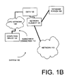
Figures 1A-1C illustrate systems for enabling subscriber service selection over non-channelized media, according to one embodiment of the invention. As will be described in more detail below, asystem 100 ofFigure 1A illustrates a system of communications that can be based on a number of protocols and configurations, while asystem 150 ofFigure 1B and asystem 160 ofFigure 1C illustrate systems of communications based on specific types of protocols and configurations. In particular, thesystem 150 ofFigure 1B illustrates a system of communications based on a cable infrastructure, while thesystem 160 ofFigure 1C illustrates a system of communications based on an infrastructure that employs DSL/Asynchronous Transfer Mode (ATM) and Ethernet. These systems are by way of example and not by way of limitation, as other systems based on other types of protocols and having other types of configurations can incorporate embodiments of the invention. For example, embodiments of the inventions can be incorporated into a wireless infrastructure, wherein wireless concentrators can route data from client devices into the network elements described herein. - With regard to
Figure 1A , asystem 100 comprises acomputing device 102, anetwork element 104, adatabase server 108 and anetwork 110. As shown, thecomputing device 102 is coupled to thenetwork element 104 through asubscriber connection 112. Thenetwork element 104 is also coupled to thedatabase server 108 and thenetwork 110. In an embodiment, thenetwork element 104 is coupled to thedatabase server 108 through thenetwork 110. In another embodiment, thenetwork element 104 is coupled to thedatabase server 108 through a network that is separate from thenetwork 110. - In one embodiment, the
network 110 is a local area network (LAN). In an embodiment, thenetwork 110 is a wide area network (WAN). Further, thenetwork 110 may be a combination of different networks that couple thenetwork element 104 to other computing devices and network elements coupled thereto. In an embodiment, thenetwork element 104 is coupled to receive data fromclient device 102 over non-channelized media - In one embodiment, the
database server 108 stores data for a number of subscribers and their associated subscriber connections. In an embodiment, thedatabase server 108 stores data related to authentication, authorization and accounting for subscribers coupled to different network elements within a network. In one embodiment, thedatabase server 108 is a RADIUS server for storing this data regarding subscribers and the associated subscriber connections. In one embodiment, thenetwork element 104 enables subscriber service selection over non-channelized media, as will be described in more detail below. -
Figure 1B illustrates asystem 150 for routing data in an infrastructure for a cable environment. Similar to thesystem 100, thesystem 150 comprises thecomputing device 102, thenetwork element 104, thedatabase server 108 and thenetwork 110. Thesystem 150 also comprises a hybrid fiber coaxial cable (HFC)network 120 and a cable modem transmission system (CMTS) 122. As shown, theHFC network 120 is coupled to thecomputing device 102 and theCMTS 122. Additionally, theCMTS 122 is coupled to thenetwork element 104. Accordingly, communications between thecomputing device 102 and thenetwork element 104 are routed through theHFC network 120 and theCMTS 122. - In an embodiment, the
HFC network 120 is a cable infrastructure that combines the radio frequency (RF) data communications of a number ofcomputing devices 102 that are forwarded to theCMTS 122. In an embodiment, the CMTS converts the RF data communications into data packets, such as Internet Protocol (IP) packets, to be routed by thenetwork element 104. -
Figure 1C illustrates asystem 160 for routing data in an infrastructure for a DSL and Ethernet environment. Similar to thesystem 100, thesystem 160 comprises thecomputing device 102, thenetwork element 104, thedatabase server 108 and thenetwork 110. Thesystem 160 also comprises a Digital Subscriber Line Access Multiplexer (DLSAM) 124, an Asynchronous Transfer Mode (ATM)network 126 and acomputing device 132. - As shown, the
computing device 102 is coupled to the network 104 (via the subscriber connection 112) through theDSLAM 124 and theATM network 126. Thecomputing device 132 is coupled to thenetwork element 104 through anEthernet communications 134. - As is known in the art, the
DSLAM 124 is a device within a network that combines a number of DSL communications into a single ATM transmission. TheATM network 126 comprises a number of communication links for routing data based on the ATM protocol. Accordingly, in an embodiment, the communications from thecomputing device 102 is received into thenetwork element 104 as data based on the ATM protocol. Additionally, as shown, thecomputing device 132 and thenetwork element 104 communicate based on the Ethernet protocol through Ethernet communications link 134. The operations of the systems illustrated inFigures 1A-1C will be described in more detail below. -
Figure 2 illustrates a block diagram of a network element, according to an embodiment of the invention. In particular,Figure 2 illustrates a more detailed block diagram of thenetwork element 104. As shown, thenetwork element 104 includes traffic cards 202-208. Thenetwork element 104 also includes acontrol card 210 and aforwarding card 212. - In an embodiment, each of the traffic cards 202-208 and the
forwarding card 212 can include a processor and memory. Additionally, thecontrol card 210 is described in more detail below in conjunction withFigure 3 . The traffic cards 202-208, thecontrol card 210 and theforwarding card 212 are coupled to system buses. In an embodiment, thecontrol card 210 performs control, system configuration and management tasks for thenetwork element 104. For example, if theforwarding card 212 needs to be updated with a new Internet Protocol (IP) address table, such data is received by thecontrol card 210 and transmitted to theforwarding card 212, wherein such data is updated therein. - Additionally, as will be described in more detail below, the
control card 210 includes memory that stores addresses assigned and/or to be assigned to client devices coupled to thenetwork element 104. For example, returning toFigures 1A-1C , when theclient device 102 is attempting to couple to thenetwork 110 through thenetwork element 104, a series of communications are exchanged between theclient device 102 and thenetwork element 104 in order to assign an address to the client device 102 (as will be described in more detail below). - Moreover, the
forwarding card 212 provides for buffering, packet processing and forwarding of data packets being received by the traffic cards 202-208. In particular, the traffic cards 202-208 can be coupled to a number of data transmission lines, which are coupled to other network elements and/or computing devices, as shown inFigure 1 . Accordingly, the traffic cards 202-208 receive and transmit data traffic from and to data transmission lines coupled thereto. Such data traffic is transmitted to theforwarding card 212, where this traffic can be buffered, processed and/or forwarded to other traffic cards within thenetwork element 104, as will be described in more detail below. - The embodiment of the
network element 104 is by way of example and not by way of limitation, as network elements having other architectural configurations can incorporate embodiments of the present invention. Examples of other network elements that could incorporate embodiments of the present invention could have multiple forwarding cards or have a single line card incorporating the functionality of both the forwarding and the controlling. Moreover, a network element having the forwarding functionality distributed across the traffic cards could incorporate embodiments of the present invention. -
Figure 3 illustrates a more detailed block diagram of a control card within a network element, according to one embodiment of the invention. In particular,Figure 3 illustrates a more detailed block diagram of thecontrol card 210 shown inFigure 2 . As shown, thecontrol card 210 comprises aprocessor 310, amemory 320 and acontrol engine 302. Theprocessor 310 is coupled to thecontrol engine 302 and thememory 320. Theforwarding engine 302 is coupled to thememory 320. - The
processor 310 may comprise any suitable processor architecture. Thecontrol card 210 for other embodiments may comprise more processors any of which may execute a set of instructions that are in accordance with embodiments of the invention. - Additionally, as shown, the
memory 320 stores a number of addresses 306AM. Addresses 306A-306I are those addresses for thesubnet 340A, whileaddresses 306H-306M are those addresses for the subnet 340I. Accordingly, a subnet 340 can include one to a number of addresses. Additionally, as shown, thesubnets 340A-340I are withincontexts 350A-I. Accordingly, acontext 350 can include one to a number of addresses 306. - In an embodiment, these addresses are source Internet Protocol (IP) addresses to be dynamically assigned to clients/subscribers that are coupled to the
network element 104. Thememory 320 may also store other data and/or instructions, for example, for thecontrol card 210 and may comprise any suitable memory, such as a dynamic random access memory (DRAM) for example. - In an embodiment, the
control engine 302 is a process or task that can reside within thememory 320 and/or theprocessor 310 and can be executed within theprocessor 310. However, embodiments of the invention are not so limited, as thecontrol engine 302 can be different types of hardware (such as digital logic) executing the processing described therein (which is described in more detail below). - Accordingly, the
control card 210 may include a machine-readable medium on which is stored a set of instructions (i.e., software) embodying any one, or all, of the methodologies described herein. For example, software can reside, completely or at least partially, within thememory 320 and/or within theprocessor 310. - The operations of subscriber service selection over a non-channelized media will now be described with reference to the block diagram of
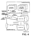
Figure 4 and the flow diagram ofFigure 5 .Figure 4 illustrates a more detailed block diagram of a network element, database server and operations and communications therewith, according to one embodiment of the invention. - As shown, the
network element 104 includesports 420A-D, interfaces 422A-D andcontexts 350A-I. AlthoughFigure 4 illustrates messaging and operations related to one port coupled to one interface of a context, in other embodiments, the different ports, interfaces and contexts of thenetwork element 104 can include the messaging and operations illustrated. In an embodiment, a number of interfaces are associated with a given port. In another embodiment, a single interface is associated with a given port. - In an embodiment,
contexts 350 are modules/units associated with a given service. For example in an embodiment, a givencontent 350 is associated with a given ISP. Accordingly, a givencontent 350 can include a number of subnets that comprise a number of addresses (e.g., Internet Protocol (IP) addresses) that are to be dynamically assigned to subscriber/clients that are coupled to thenetwork element 104. To help illustrate, a first ISP could be associated with thecontext 350A, while a second ISP could be associated with the context 350I, etc. - The
database server 108 comprises a number ofsubscriber records 450 and a number of subscriber accounting records 452. In an embodiment, a given customer premise equipment (CPE) coupled to thenetwork element 104 has an associatedsubscriber record 450 and an associatedsubscriber accounting record 452. For example, a subscriber usingclient device 102 that is connecting to thenetwork 110 through thenetwork element 104 has an associatedsubscriber record 450 and an associatedsubscriber accounting record 452. WhileFigure 4 illustrates thenetwork element 104 and thedatabase server 108 as two separate elements, embodiments of the invention are not so limited. For example, in another embodiment, thedatabase server 108 and/or the records therein can be incorporated into thenetwork element 104. - Additionally, as shown in
Figure 4 , thenetwork element 104 and thedatabase server 108 are receiving and transmitting a number of different messages as well as performing a number of operations. Thenetwork element 104 is coupled to receive anaddress request message 402. Thenetwork element 104 is to transmit a request for context message 404 to thedatabase server 108. Thedatabase server 108 is to transmit a bind tocontext message 406 back to thenetwork element 104, in a response to this request. Additionally, thenetwork element 104 performs a bind operation, (the bind to interface operation 408), to bind the assigned address for the given subscriber to the interface 422 for thecontext 350A. Thenetwork element 104 is to transmit areturn address message 410 back to theclient device 102. A more detailed description of these messages and operations is set forth below in conjunction with a flow diagram 500 ofFigure 5 . - In particular,
Figure 5 is a flow diagram for providing subscriber service selection over a non-channelized media, according to one embodiment of the invention. The operation of the flow diagram 500 will be described with reference to the exemplary systems shownFigures 1-4 . - In
block 502, a request for an address from theclient device 102 is received. With reference to the exemplary embodiment ofFigure 3 , thecontrol engine 302 receives this request. In an embodiment, the request includes an identifier of theclient device 102. In one embodiment, the identifier of theclient device 102 is the Media Access Control (MAC) Address of a customer premise equipment (such as the network card) within theclient device 102 that is communicating with thenetwork element 104. In an embodiment, the request is based on the Dynamic Host Configuration Protocol (DHCP), which allows for the assignment of Internet Protocol (IP) addresses to clients being coupled to a network, as is known in the art. In one such embodiment, the request from theclient device 102 is a DHCP discover request, which is requesting an IP address from thenetwork element 104. Returning toFigure 4 to help illustrate, theaddress request message 402 is received into thenetwork element 104 at theport 420A. Thisaddress request message 402 is being transmitted by the client device 102 (not shown inFigure 4 ). - In
block 504, a subscriber identifier is generated based on the client identifier. In an embodiment, the client identifier is converted into the subscriber identifier. With reference to the exemplary embodiment ofFigure 3 , thecontrol engine 302 generates this subscriber identifier. In an embodiment, the subscriber identifier is a username to be associated with thisclient device 102. In one embodiment, the subscriber identifier is a number of text characters that correspond to the client identifier. For example, in an embodiment wherein the client identifier is a MAC address, such as "112233445566" (which is comprised of 6 hexadecimal numbers having 12 hexadecimal nibbles), thecontrol engine 302 generates the following text characters: "11:22:33:44:55:66", wherein each hexadecimal nibble is converted to a character that corresponds to the hexadecimal value (0-9 and A-F). However, embodiments of the invention are not so limited. For example, in other embodiments, thecontrol engine 302 can generate a different subscriber identifier (based on the client identifier), using other operations, such as different ciphering operations, etc. To help illustrate, thecontrol engine 302 could convert the hexadecimal values from the MAC address to a binary value and add a constant value to this binary value and convert the individual binary values into a corresponding text character. - In
block 506, thecontext 350 for the subscriber (client) and associated subscriber attributes are retrieved. With reference to the exemplary embodiment ofFigure 3 , thecontrol engine 302 retrieves the context for the subscriber and the associated subscriber attributes. In one embodiment, thecontrol engine 302 retrieves the context and the attributes from thedatabase server 108, which stores acorresponding subscriber record 450 for this subscriber. In an embodiment, thecontrol engine 302 transmits the subscriber identifier to thedatabase server 108, wherein thedatabase server 108 retrieves the context and the associated subscriber attributes from thesubscriber record 450. Returning toFigure 4 to help illustrate, the request for the context message 404 is transmitted from thenetwork element 104 to thedatabase server 108. Thedatabase server 108 transmits the bind tocontext message 406 back to thecontrol engine 302. - In an embodiment, when the
client device 102 initially communicates with thenetwork element 104, thedatabase server 108 will not include acorresponding subscriber record 450. Accordingly, if thedatabase server 108 does not return acorresponding subscriber record 450, thecontrol engine 302 causes theclient device 102 to execute an initiation process, wherein theclient device 102 provides data to be entered into thesubscriber record 450. In an embodiment, thecontrol engine 302 redirects theclient device 102 to a web site for activating a subscriber account, wherein the different subscriber attributes, such as the ISP, the data rates (rate limiting and policing values), the access control lists, etc. are selected. Accordingly, thecontrol engine 302 can retrieve thecontext 350 for this subscriber once the subscriber account has been established. In an embodiment, when theclient device 102 requests a domain name service, thecontrol engine 302 generates a response back to theclient device 102 that includes a redirect message. Accordingly, this redirect message could be processed by a web site (described above) for activating the subscriber account. Accordingly, such a process reduces the opportunity for a new subscriber to provide fraudulent, false or incomplete data during an account subscription. - In
block 508, an address is assigned to the subscriber based on thecontext 350. With reference to the exemplary embodiment ofFigure 3 , thecontrol engine 302 assigns an address to the subscriber based on thecontext 350. As described above, a givencontext 350 can comprise a number of subnets that can comprise a number of addresses. Returning toFigure 3 , assuming that the context for this subscriber is associated with the addresses forcontext 350, thecontrol engine 302 selects one of the addresses 306 from one of the addresses ofsubnets 340A-M, which is not currently assigned, for assignment to the current subscriber. - In
block 510, a virtual circuit is generated between theclient device 102 and thenetwork element 104. With reference to the exemplary embodiment ofFigure 3 , thecontrol engine 302 generates this virtual circuit between theclient device 102 and thenetwork element 104. In one embodiment, a given subscriber session has a one-to-one correspondence to a given virtual circuit. In one embodiment, a given transmission line (a real circuit) can include a number of virtual circuits. In particular, when theclient device 102 is assigned an address for this given subscriber session, data packets received and transmitted from theclient device 102 include this address in order to associate the data packets with the subscriber session (and therefore the associated virtual circuit). Returning toFigure 4 to help illustrate, in conjunction with the creation of the virtual circuit, thecontrol engine 302 binds the address to the interface 422, as illustrated by the bind to interface operation 408. Additionally, as shown inFigure 4 , as part of the generation of the virtual circuit, thecontrol engine 302 returns the requested address back to theclient device 102, as illustrated by thereturn address message 410. - In an embodiment wherein the DHCP protocol is employed for the assignment of the address, the
control engine 302 generates an DHCP offer request that is transmitted back to the requestingclient device 102. In turn, if theclient device 102 accepts the address, theclient device 102 transmits a request back to thenetwork element 104. Thecontrol engine 302 transmits back an acknowledge of this acceptance. - In
block 512, the account for the subscriber is updated. With reference to the exemplary embodiment ofFigure 3 , thecontrol engine 302 updates the account for the subscriber. In an embodiment, thecontrol engine 302 generates an accounting message that indicates that there is an active subscriber session associated with this given subscriber, identified by the subscriber identifier (described above). Thecontrol engine 302 transmits this account message to thedatabase server 108. Returning toFigure 4 to help illustrate, thecontrol engine 302 transmits this account update (update accounting message 412) to thedatabase server 108. Accordingly, thedatabase server 108 updates the correspondingsubscriber accounting record 452. Additionally, although described such that thedatabase server 108 updates a givensubscriber accounting record 452, in a different embodiment, thedatabase server 108 includes a log file such that modifications to a given subscriber account is appended to the log file. In another embodiment, instead of updating the account for the subscriber, these updates to the account are transmitted to thedatabase server 108 as part of periodic updates for given subscriber accounts. - The servers as well as the traffic cards, forwarding cards and control cards included in the different network elements include memories, processors and/or Application Specific Integrated Circuits (ASICs). Such memory includes a machine-readable medium on which is stored a set of instructions (i. e. , software) embodying any one, or all, of the methodologies described herein. Software can reside, completely or at least partially, within this memory and/or within the processor and/or ASICs. For the purposes of this specification, the term "machine-readable medium" shall be taken to include any mechanism that provides (i. e. , stores and/or transmits) information in a form readable by a machine (e. g. , a computer). For example, a machine-readable medium includes read only memory (ROM); random access memory (RAM); magnetic disk storage media; optical storage media; flash memory devices; electrical, optical, acoustical or other form of propagated signals (e. g. , carrier waves, infrared signals, digital signals, etc.); etc.
- Thus, a method and apparatus for enabling subscriber service selection over non-channelized media have been described. Although the present invention has been described with reference to specific exemplary embodiments, it will be evident that various modifications and changes may be made to these embodiments without departing from the broader scope of the invention. For example, while embodiments of the invention are described such that a separate database server is coupled to store data related to subscriber connections. Accordingly, the specification and drawings are to be regarded in an illustrative rather than a restrictive sense.
Claims (22)
- A method performed by a network element, the method comprising the steps of:receiving a request from a computing device (102) for an address, the request including a unique identifier associated with the computing device (102);characterised in that the method comprises:generating a username based on the unique identifier, the username associated with the computing device (102);sending the username to an authentication, authorization, and accounting AAA server (108), wherein the AAA server is a RADIUS server;determining a context for the computing device based on a response from the AAA server (108), wherein the context includes a number of assignable addresses;assigning an address to the computing device (102) within the context; andgenerating a virtual circuit between the computing device (102) and the network element (104) based on the address.
- The method of claim 1, further comprising the step of selecting the context based on the username.
- The method of claim 1, wherein assigning the address to the computing device (102) comprises assigning an Internet Protocol address to the computing device (102).
- The method of claim 1, wherein the unique identifier comprises a number of decimal values and wherein the username comprises a number of text characters corresponding to the number of decimal values.
- The method of claim 1 further comprising the step of:retrieving based on the username a service selected from a plurality of services, and attributes for the selected service associated with the context, wherein the username is a subscriber identifier, and the address is assigned from the context based on the selected service.
- The method of claim 1, further comprising the steps of:upon determining that the username does not have a corresponding record in the AAA server (108), activating a subscriber account by,
redirecting the computing device to a web site to allow selection of a service from multiple services, where the address assigned is an IP address corresponding to the selected service; andcausing an updating of the subscriber's account to reflect an active subscriber session. - The method of claim 1, further comprising the steps of:upon determining that the username has a record in the AAA server (108),
determining which one of a plurality of services is selected, wherein the assigned address is based upon the selected service, and
updating the record associated with the username to reflect an active session. - The method of any one of claims 1, 3, 5, 6 and 7, wherein the unique identifier is a Media Access Control address.
- The method of any one of claims 6 or 7, wherein the selection of the service includes selecting a service provider and/or data rates.
- The method of claim 5, further comprising the step of:causing an updating of an account associated with the username.
- The method of any one of claims 1, 3 or 8, wherein the request is a DHCP discovery request.
- The method of any one of claims 1 or 11 wherein:the step of receiving includes receiving the request from the computing device (102) over non-channelized media.
- An apparatus comprising:a network element (104) including,
a traffic card (202-208) that includes a port (420) for receiving data from a client device (102), the traffic card (202-208) to receive a request for a source address on the port (420), wherein the request includes an identification of the client device (102); and
a control card (102) coupled to the traffic card (202-208), wherein the control card (210) comprises a control engine (302),characterised in that the control engine (302) is arranged to:generate a username based on the identification of the client device (102),retrieve based on the username a context, selected from a plurality of contexts, and associated subscriber attributes, wherein the control engine (302) as part of the retrieval is arranged to
send the username to an authentication, authorization, and accounting AAA server (108), wherein the AAA server is a RADIUS server;
determine the context for the client device based on a response from the AAA server (108), wherein the context includes a number of assignable addresses;assign a source address to the client device (102) based on the selected context, andcause an updating of an account for the client device (102). - The apparatus of claim 13, wherein the control engine (302) is arranged to cause the client device (102) to activate a subscriber account when the username is not found in the AAA server (108).
- The apparatus of claim 13, wherein the control engine (302) is arranged to generate a circuit between the port on the traffic card and the client device (102) based on the assigned source address.
- The apparatus of claim 13, wherein the identification of the client device (102) is a Media Access Control address.
- The apparatus of claim 16, wherein the username comprises a number of text characters that correspond to the Media Access Control address.
- The apparatus of claim 13:wherein the network element (104) is coupled to a website to allow the subscriber to select a service from a plurality of services;wherein the request is a Dynamic Host Configuration Protocol "DHCP" request for an Internet Protocol "IP" address on the port;wherein the control card (210) is also arranged to redirect the client device to the website upon determining the username does not have a corresponding record in the AAA server (108).
- The apparatus of claim 18, wherein the selection of the service includes selecting a service provider and/or data rates.
- The apparatus of claim 16, wherein:the request is a Dynamic Host Configuration Protocol "DHCP" request for an Internet Protocol "IP" address.
- The apparatus of any one of claims 16 or 20, wherein the port is connected to non-channelized media.
- A computer program which, when executed by a processor, carries out a method according to any one of claims 1 to 12.
Priority Applications (1)
| Application Number | Priority Date | Filing Date | Title |
|---|---|---|---|
| EP14173768.4A EP2854343B1 (en) | 2002-04-26 | 2003-04-25 | Subscriber service selection over non-channelized media |
Applications Claiming Priority (3)
| Application Number | Priority Date | Filing Date | Title |
|---|---|---|---|
| US10/133,072 US7895304B1 (en) | 2002-04-26 | 2002-04-26 | Subscriber service selection over non-channelized media |
| US133072 | 2002-04-26 | ||
| PCT/US2003/012862 WO2003091963A2 (en) | 2002-04-26 | 2003-04-25 | Subscriber service selection over non-channelized media |
Related Child Applications (2)
| Application Number | Title | Priority Date | Filing Date |
|---|---|---|---|
| EP14173768.4A Division-Into EP2854343B1 (en) | 2002-04-26 | 2003-04-25 | Subscriber service selection over non-channelized media |
| EP14173768.4A Division EP2854343B1 (en) | 2002-04-26 | 2003-04-25 | Subscriber service selection over non-channelized media |
Publications (3)
| Publication Number | Publication Date |
|---|---|
| EP1500060A2 EP1500060A2 (en) | 2005-01-26 |
| EP1500060A4 EP1500060A4 (en) | 2010-06-02 |
| EP1500060B1 true EP1500060B1 (en) | 2014-08-06 |
Family
ID=29268771
Family Applications (2)
| Application Number | Title | Priority Date | Filing Date |
|---|---|---|---|
| EP14173768.4A Expired - Lifetime EP2854343B1 (en) | 2002-04-26 | 2003-04-25 | Subscriber service selection over non-channelized media |
| EP03726459.5A Expired - Lifetime EP1500060B1 (en) | 2002-04-26 | 2003-04-25 | Subscriber service selection over non-channelized media |
Family Applications Before (1)
| Application Number | Title | Priority Date | Filing Date |
|---|---|---|---|
| EP14173768.4A Expired - Lifetime EP2854343B1 (en) | 2002-04-26 | 2003-04-25 | Subscriber service selection over non-channelized media |
Country Status (6)
| Country | Link |
|---|---|
| US (3) | US7895304B1 (en) |
| EP (2) | EP2854343B1 (en) |
| JP (2) | JP4583166B2 (en) |
| AU (1) | AU2003228694A1 (en) |
| HK (1) | HK1073006A1 (en) |
| WO (1) | WO2003091963A2 (en) |
Families Citing this family (9)
| Publication number | Priority date | Publication date | Assignee | Title |
|---|---|---|---|---|
| US7895304B1 (en) | 2002-04-26 | 2011-02-22 | Ericsson Ab | Subscriber service selection over non-channelized media |
| JP4704255B2 (en) * | 2006-03-17 | 2011-06-15 | 株式会社沖データ | Image processing device |
| US9317820B1 (en) * | 2010-03-31 | 2016-04-19 | Emc Corporation | System and method for configuring a cloud computing space |
| KR20110120651A (en) * | 2010-04-29 | 2011-11-04 | 한국전자통신연구원 | Multi-services automatic identification method, and method of providing multi-services using the same |
| CN103973821B (en) * | 2013-01-28 | 2017-10-27 | 中兴通讯股份有限公司 | CPE upper portal website's promotion method and CPE based on MAC Address |
| CA2876708C (en) * | 2013-12-31 | 2022-05-03 | Bce Inc. | Authorizing a computing device across services |
| US9521033B2 (en) | 2014-02-23 | 2016-12-13 | Telefonaktiebolaget L M Ericsson (Publ) | IPoE dual-stack subscriber for bridged residential gateway configuration |
| WO2015170393A1 (en) * | 2014-05-09 | 2015-11-12 | 三菱電機株式会社 | Rotating electric machine, and mounting method for element wire temperature measurement sensor of rotating electric machine |
| CA3040887A1 (en) * | 2016-10-18 | 2018-04-26 | Src Labs, Llc | Fpga platform as a service (paas) |
Family Cites Families (36)
| Publication number | Priority date | Publication date | Assignee | Title |
|---|---|---|---|---|
| DE19521484A1 (en) | 1995-06-13 | 1996-12-19 | Deutsche Telekom Ag | Method and device for authenticating subscribers to digital switching centers |
| US5610910A (en) * | 1995-08-17 | 1997-03-11 | Northern Telecom Limited | Access to telecommunications networks in multi-service environment |
| US6098116A (en) * | 1996-04-12 | 2000-08-01 | Fisher-Rosemont Systems, Inc. | Process control system including a method and apparatus for automatically sensing the connection of devices to a network |
| US6658010B1 (en) * | 1996-07-25 | 2003-12-02 | Hybrid Networks, Inc. | High-speed internet access system |
| US6370122B1 (en) | 1996-08-27 | 2002-04-09 | Siemens Schweiz Ag | Method for monitoring and checking subscriber connections to ISDN |
| US6073178A (en) * | 1996-12-09 | 2000-06-06 | Sun Microsystems, Inc. | Method and apparatus for assignment of IP addresses |
| JPH10210066A (en) * | 1997-01-16 | 1998-08-07 | Sumitomo Electric Ind Ltd | Data base for judging internet work repeating destination and method for constructing data base |
| US6078568A (en) | 1997-02-25 | 2000-06-20 | Telefonaktiebolaget Lm Ericsson | Multiple access communication network with dynamic access control |
| JP3529621B2 (en) * | 1997-05-12 | 2004-05-24 | 株式会社東芝 | Router device, datagram transfer method, and communication system |
| US6070243A (en) | 1997-06-13 | 2000-05-30 | Xylan Corporation | Deterministic user authentication service for communication network |
| JPH1155256A (en) | 1997-08-06 | 1999-02-26 | Fujitsu Ltd | Re-connection processing method for multi-point connection |
| SE515083C2 (en) | 1997-11-11 | 2001-06-05 | B2 Tech Ab C O Bredbandsbolage | Method and device for Internet telephony via broadband connections |
| US20010019559A1 (en) | 1998-01-09 | 2001-09-06 | Gemini Networks, Inc. | System, method, and computer program product for end-user self-authentication |
| JPH11355303A (en) | 1998-06-11 | 1999-12-24 | Ntt Data Corp | Computer identification system and its method |
| US6112246A (en) | 1998-10-22 | 2000-08-29 | Horbal; Mark T. | System and method for accessing information from a remote device and providing the information to a client workstation |
| US6609153B1 (en) * | 1998-12-24 | 2003-08-19 | Redback Networks Inc. | Domain isolation through virtual network machines |
| JP3558908B2 (en) | 1999-01-14 | 2004-08-25 | 日本電信電話株式会社 | ACCESS POINT SELECTION CONNECTION SYSTEM AND STORAGE MEDIUM RECORDING THE PROGRAM |
| WO2001019080A2 (en) | 1999-09-03 | 2001-03-15 | Ericsson Inc | Automatic configuration of cable modems |
| US6603758B1 (en) * | 1999-10-01 | 2003-08-05 | Webtv Networks, Inc. | System for supporting multiple internet service providers on a single network |
| JP2001156846A (en) | 1999-11-29 | 2001-06-08 | Pfu Ltd | Address automatic assignment device and recording medium |
| US6912567B1 (en) * | 1999-12-27 | 2005-06-28 | International Business Machines Corp. | Broadband multi-service proxy server system and method of operation for internet services of user's choice |
| US6618858B1 (en) * | 2000-05-11 | 2003-09-09 | At Home Liquidating Trust | Automatic identification of a set-top box user to a network |
| US6880086B2 (en) * | 2000-05-20 | 2005-04-12 | Ciena Corporation | Signatures for facilitating hot upgrades of modular software components |
| JP3457259B2 (en) | 2000-05-30 | 2003-10-14 | 日本電信電話株式会社 | Provider switching communication method and device |
| JP2001350937A (en) | 2000-06-06 | 2001-12-21 | Toshiba Corp | Method and system for lending address and computer readable recording medium |
| JP2002026954A (en) * | 2000-07-03 | 2002-01-25 | Nec Soft Ltd | Network address management system and its method |
| US20020114274A1 (en) * | 2000-09-19 | 2002-08-22 | Sturges James H. | Packet based network for supporting real time applications |
| US6920506B2 (en) * | 2001-06-28 | 2005-07-19 | Canon Information Systems, Inc. | Discovery and management of network printers |
| US7720045B2 (en) | 2003-05-02 | 2010-05-18 | Microsoft Corporation | Method to enable simultaneous connections to multiple wireless networks using a single radio |
| US20030145075A1 (en) * | 2002-01-29 | 2003-07-31 | Weaver David John | Diagnostics and network provisioning tool for bi-directional communication devices |
| US7895304B1 (en) | 2002-04-26 | 2011-02-22 | Ericsson Ab | Subscriber service selection over non-channelized media |
| US20040131078A1 (en) | 2003-01-03 | 2004-07-08 | Gupta Vivek G. | Apparatus and method for supporting multiple wireless technologies within a device |
| US9053063B2 (en) | 2007-02-21 | 2015-06-09 | At&T Intellectual Property I, Lp | Method and apparatus for authenticating a communication device |
| US8681695B1 (en) | 2009-10-14 | 2014-03-25 | Juniper Networks, Inc. | Single address prefix allocation within computer networks |
| CN102404293A (en) | 2010-09-15 | 2012-04-04 | 中兴通讯股份有限公司 | Dual-stack user managing method and broadband access server |
| US8769623B2 (en) | 2011-09-29 | 2014-07-01 | Cisco Technology, Inc. | Grouping multiple network addresses of a subscriber into a single communication session |
-
2002
- 2002-04-26 US US10/133,072 patent/US7895304B1/en active Active
-
2003
- 2003-04-25 WO PCT/US2003/012862 patent/WO2003091963A2/en active Search and Examination
- 2003-04-25 EP EP14173768.4A patent/EP2854343B1/en not_active Expired - Lifetime
- 2003-04-25 JP JP2004500262A patent/JP4583166B2/en not_active Expired - Lifetime
- 2003-04-25 AU AU2003228694A patent/AU2003228694A1/en not_active Abandoned
- 2003-04-25 EP EP03726459.5A patent/EP1500060B1/en not_active Expired - Lifetime
-
2005
- 2005-07-14 HK HK05106021.5A patent/HK1073006A1/en not_active IP Right Cessation
-
2009
- 2009-10-15 US US12/580,215 patent/US8321550B2/en not_active Expired - Lifetime
-
2010
- 2010-03-24 JP JP2010067983A patent/JP5128626B2/en not_active Expired - Lifetime
-
2011
- 2011-02-22 US US13/032,624 patent/US9319235B2/en active Active
Also Published As
| Publication number | Publication date |
|---|---|
| US20100034364A1 (en) | 2010-02-11 |
| EP1500060A4 (en) | 2010-06-02 |
| HK1073006A1 (en) | 2005-09-16 |
| EP2854343B1 (en) | 2015-10-21 |
| AU2003228694A1 (en) | 2003-11-10 |
| WO2003091963A2 (en) | 2003-11-06 |
| US7895304B1 (en) | 2011-02-22 |
| JP5128626B2 (en) | 2013-01-23 |
| JP4583166B2 (en) | 2010-11-17 |
| US8321550B2 (en) | 2012-11-27 |
| EP2854343A1 (en) | 2015-04-01 |
| US9319235B2 (en) | 2016-04-19 |
| EP1500060A2 (en) | 2005-01-26 |
| WO2003091963A3 (en) | 2003-12-11 |
| US20110145379A1 (en) | 2011-06-16 |
| JP2005524269A (en) | 2005-08-11 |
| JP2010183614A (en) | 2010-08-19 |
Similar Documents
| Publication | Publication Date | Title |
|---|---|---|
| US9319235B2 (en) | Authentication, authorization, and accounting based on an automatically generated username | |
| EP1535449B1 (en) | System and method for dynamic simultaneous connection to multiple service providers | |
| CN101026519B (en) | Dynamic building of VLAN interfaces based on subscriber information | |
| US9667758B2 (en) | Dynamic modification of a subscriber connection | |
| WO2003077143A1 (en) | Providing multiple isp access to devices behind nat | |
| US8005112B2 (en) | Service connection method and architecture | |
| WO2008024226A1 (en) | Method and system for inter working a point-to-point link and a lan service | |
| US20040098468A1 (en) | Multi internet service provider system and method of the same | |
| Cisco | APPN Configuration Commands | |
| Cisco | APPN Configuration Commands | |
| JP2003504898A (en) | Addressing methods and name and address servers in digital networks | |
| US7216175B1 (en) | System and method for determining subscriber information | |
| US20060072601A1 (en) | Virtual IP interface | |
| JPH1084359A (en) | Service management system |
Legal Events
| Date | Code | Title | Description |
|---|---|---|---|
| PUAI | Public reference made under article 153(3) epc to a published international application that has entered the european phase |
Free format text: ORIGINAL CODE: 0009012 |
|
| 17P | Request for examination filed |
Effective date: 20040909 |
|
| AK | Designated contracting states |
Kind code of ref document: A2 Designated state(s): AT BE BG CH CY CZ DE DK EE ES FI FR GB GR HU IE IT LI LU MC NL PT RO SE SI SK TR |
|
| AX | Request for extension of the european patent |
Extension state: AL LT LV MK |
|
| REG | Reference to a national code |
Ref country code: HK Ref legal event code: DE Ref document number: 1073006 Country of ref document: HK |
|
| A4 | Supplementary search report drawn up and despatched |
Effective date: 20100429 |
|
| RIC1 | Information provided on ipc code assigned before grant |
Ipc: H04L 29/12 20060101ALN20100423BHEP Ipc: H04L 12/28 20060101AFI20100423BHEP |
|
| RAP1 | Party data changed (applicant data changed or rights of an application transferred) |
Owner name: ERICSSON AB |
|
| 17Q | First examination report despatched |
Effective date: 20110614 |
|
| GRAP | Despatch of communication of intention to grant a patent |
Free format text: ORIGINAL CODE: EPIDOSNIGR1 |
|
| RIC1 | Information provided on ipc code assigned before grant |
Ipc: H04L 12/28 20060101AFI20131010BHEP Ipc: H04L 29/12 20060101ALN20131010BHEP |
|
| INTG | Intention to grant announced |
Effective date: 20131030 |
|
| RIC1 | Information provided on ipc code assigned before grant |
Ipc: H04L 12/28 20060101AFI20131021BHEP Ipc: H04L 29/12 20060101ALN20131021BHEP Ipc: H04W 4/20 20090101ALI20131021BHEP Ipc: H04W 4/02 20090101ALI20131021BHEP |
|
| GRAS | Grant fee paid |
Free format text: ORIGINAL CODE: EPIDOSNIGR3 |
|
| GRAA | (expected) grant |
Free format text: ORIGINAL CODE: 0009210 |
|
| AK | Designated contracting states |
Kind code of ref document: B1 Designated state(s): DE FR GB |
|
| REG | Reference to a national code |
Ref country code: GB Ref legal event code: FG4D |
|
| REG | Reference to a national code |
Ref country code: DE Ref legal event code: R096 Ref document number: 60346592 Country of ref document: DE Effective date: 20140918 |
|
| REG | Reference to a national code |
Ref country code: HK Ref legal event code: GR Ref document number: 1073006 Country of ref document: HK |
|
| REG | Reference to a national code |
Ref country code: DE Ref legal event code: R097 Ref document number: 60346592 Country of ref document: DE |
|
| PLBE | No opposition filed within time limit |
Free format text: ORIGINAL CODE: 0009261 |
|
| STAA | Information on the status of an ep patent application or granted ep patent |
Free format text: STATUS: NO OPPOSITION FILED WITHIN TIME LIMIT |
|
| 26N | No opposition filed |
Effective date: 20150507 |
|
| REG | Reference to a national code |
Ref country code: FR Ref legal event code: PLFP Year of fee payment: 14 |
|
| REG | Reference to a national code |
Ref country code: FR Ref legal event code: PLFP Year of fee payment: 15 |
|
| REG | Reference to a national code |
Ref country code: FR Ref legal event code: PLFP Year of fee payment: 16 |
|
| PGFP | Annual fee paid to national office [announced via postgrant information from national office to epo] |
Ref country code: GB Payment date: 20220427 Year of fee payment: 20 Ref country code: FR Payment date: 20220425 Year of fee payment: 20 Ref country code: DE Payment date: 20220427 Year of fee payment: 20 |
|
| REG | Reference to a national code |
Ref country code: DE Ref legal event code: R071 Ref document number: 60346592 Country of ref document: DE |
|
| REG | Reference to a national code |
Ref country code: GB Ref legal event code: PE20 Expiry date: 20230424 |
|
| PG25 | Lapsed in a contracting state [announced via postgrant information from national office to epo] |
Ref country code: GB Free format text: LAPSE BECAUSE OF EXPIRATION OF PROTECTION Effective date: 20230424 |