EP1498788A1 - Display device for timepiece - Google Patents
Display device for timepiece Download PDFInfo
- Publication number
- EP1498788A1 EP1498788A1 EP03405532A EP03405532A EP1498788A1 EP 1498788 A1 EP1498788 A1 EP 1498788A1 EP 03405532 A EP03405532 A EP 03405532A EP 03405532 A EP03405532 A EP 03405532A EP 1498788 A1 EP1498788 A1 EP 1498788A1
- Authority
- EP
- European Patent Office
- Prior art keywords
- display
- gear
- train
- wheel
- disc
- Prior art date
- Legal status (The legal status is an assumption and is not a legal conclusion. Google has not performed a legal analysis and makes no representation as to the accuracy of the status listed.)
- Withdrawn
Links
- 230000007246 mechanism Effects 0.000 claims abstract description 33
- 230000033001 locomotion Effects 0.000 claims abstract description 29
- 238000005259 measurement Methods 0.000 claims description 10
- 230000001276 controlling effect Effects 0.000 claims description 5
- 210000000056 organ Anatomy 0.000 claims description 2
- 230000001105 regulatory effect Effects 0.000 claims description 2
- 238000012549 training Methods 0.000 description 15
- 238000004804 winding Methods 0.000 description 13
- 230000000694 effects Effects 0.000 description 6
- 230000000717 retained effect Effects 0.000 description 3
- 230000000295 complement effect Effects 0.000 description 2
- 239000010453 quartz Substances 0.000 description 2
- VYPSYNLAJGMNEJ-UHFFFAOYSA-N silicon dioxide Inorganic materials O=[Si]=O VYPSYNLAJGMNEJ-UHFFFAOYSA-N 0.000 description 2
- 108091028072 EteRNA Proteins 0.000 description 1
- 230000003042 antagnostic effect Effects 0.000 description 1
- 238000012550 audit Methods 0.000 description 1
- 230000000903 blocking effect Effects 0.000 description 1
- 239000000470 constituent Substances 0.000 description 1
- 230000000994 depressogenic effect Effects 0.000 description 1
- 239000002184 metal Substances 0.000 description 1
- 235000020004 porter Nutrition 0.000 description 1
- 230000035945 sensitivity Effects 0.000 description 1
- 230000035939 shock Effects 0.000 description 1
- 239000003381 stabilizer Substances 0.000 description 1
Images


Classifications
-
- G—PHYSICS
- G04—HOROLOGY
- G04B—MECHANICALLY-DRIVEN CLOCKS OR WATCHES; MECHANICAL PARTS OF CLOCKS OR WATCHES IN GENERAL; TIME PIECES USING THE POSITION OF THE SUN, MOON OR STARS
- G04B19/00—Indicating the time by visual means
- G04B19/24—Clocks or watches with date or week-day indicators, i.e. calendar clocks or watches; Clockwork calendars
-
- G—PHYSICS
- G04—HOROLOGY
- G04B—MECHANICALLY-DRIVEN CLOCKS OR WATCHES; MECHANICAL PARTS OF CLOCKS OR WATCHES IN GENERAL; TIME PIECES USING THE POSITION OF THE SUN, MOON OR STARS
- G04B1/00—Driving mechanisms
- G04B1/10—Driving mechanisms with mainspring
- G04B1/12—Driving mechanisms with mainspring with several mainsprings
-
- G—PHYSICS
- G04—HOROLOGY
- G04B—MECHANICALLY-DRIVEN CLOCKS OR WATCHES; MECHANICAL PARTS OF CLOCKS OR WATCHES IN GENERAL; TIME PIECES USING THE POSITION OF THE SUN, MOON OR STARS
- G04B1/00—Driving mechanisms
- G04B1/10—Driving mechanisms with mainspring
- G04B1/22—Compensation of changes in the motive power of the mainspring
- G04B1/225—Compensation of changes in the motive power of the mainspring with the aid of an interposed power-accumulator (secondary spring) which is always tensioned
-
- G—PHYSICS
- G04—HOROLOGY
- G04B—MECHANICALLY-DRIVEN CLOCKS OR WATCHES; MECHANICAL PARTS OF CLOCKS OR WATCHES IN GENERAL; TIME PIECES USING THE POSITION OF THE SUN, MOON OR STARS
- G04B19/00—Indicating the time by visual means
- G04B19/20—Indicating by numbered bands, drums, discs, or sheets
- G04B19/202—Indicating by numbered bands, drums, discs, or sheets by means of turning discs
-
- G—PHYSICS
- G04—HOROLOGY
- G04F—TIME-INTERVAL MEASURING
- G04F7/00—Apparatus for measuring unknown time intervals by non-electric means
- G04F7/04—Apparatus for measuring unknown time intervals by non-electric means using a mechanical oscillator
- G04F7/08—Watches or clocks with stop devices, e.g. chronograph
- G04F7/0804—Watches or clocks with stop devices, e.g. chronograph with reset mechanisms
-
- G—PHYSICS
- G04—HOROLOGY
- G04F—TIME-INTERVAL MEASURING
- G04F7/00—Apparatus for measuring unknown time intervals by non-electric means
- G04F7/04—Apparatus for measuring unknown time intervals by non-electric means using a mechanical oscillator
- G04F7/08—Watches or clocks with stop devices, e.g. chronograph
- G04F7/0842—Watches or clocks with stop devices, e.g. chronograph with start-stop control mechanisms
-
- G—PHYSICS
- G04—HOROLOGY
- G04F—TIME-INTERVAL MEASURING
- G04F7/00—Apparatus for measuring unknown time intervals by non-electric means
- G04F7/04—Apparatus for measuring unknown time intervals by non-electric means using a mechanical oscillator
- G04F7/08—Watches or clocks with stop devices, e.g. chronograph
- G04F7/0866—Special arrangements
- G04F7/089—Special arrangements indicating measured time by other than hands, e.g. numbered bands, drums, discs or sheet
-
- G—PHYSICS
- G04—HOROLOGY
- G04F—TIME-INTERVAL MEASURING
- G04F7/00—Apparatus for measuring unknown time intervals by non-electric means
- G04F7/04—Apparatus for measuring unknown time intervals by non-electric means using a mechanical oscillator
- G04F7/08—Watches or clocks with stop devices, e.g. chronograph
- G04F7/0866—Special arrangements
- G04F7/0895—Special arrangements with a separate barrel for the chronograph functions
Definitions
- a disk is understood to mean a round piece, generally made of plastic or metal, which can be pierced or not in its center and carries indications to display.
- Display of information by means of one or more disks is known of the skilled person.
- One of the most frequent applications concerns indication of the day and date, the display being done by means of two discs, which make a jump a day.
- the movement is usually provided with a spring, armed by the gear of finishing, which relaxes around midnight, thus making the day and the day the following indication. It can also be driven at first in a slow motion ensured by the cogwheel of the watch, then by a jump generated by a jumper.
- the purpose of the present invention is to ensure optimal training of the discs, even of great size and without affecting the good running of the watch.
- the second source of energy is mechanical, at like a barrel.
- the device according to the invention furthermore comprises means of arming this source of energy.
- the device comprises drive means driven by the wheel of chronograph and commanding drive the display gear by the barrel.
- the display gear is arranged in such a way that the disc ensures the display of timed times greater than or equal to the minute.
- Such a device may include several display disks and several barrels, each barrel driving a disc.
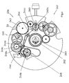
- the watch shown in FIG. 1 comprises a box 10 defining a housing within which is a movement.
- the latter is equipped of a chronograph mechanism, well known in itself, as well as a device display according to the invention which will be described in more detail below.
- Dial 12 has three wickets through of which discs 24, 26 and 28 appear, respectively displaying the hours, tens of minutes and minutes units of time timed, thus ensuring the display function of the device according to the invention.
- a winding crown and time setting 30 and pushers 31 and 32 are arranged in a conventional manner, on the edge of the box 10.
- the crown 30 provides the necessary mechanical energy to the operation of the movement, by winding a mainspring, as will be explained later.
- the pushers 31 and 32 control respectively the start and stop, and the zeroing of the chronograph and its display device.
- the base of the movement consists of a chronograph caliber such as marketed by ETA SA (Switzerland) under the reference 7750.
- This movement comprises a plate 33, visible in FIG. chronograph and a start and stop mechanism, which are only very partially visible in the drawing, being well known to those skilled in the art.
- he comprises, in addition, a barrel, a finishing gear, an exhaust and a pendulum.
- the barrel brings energy to the wheel of finishing, which delivers it to the exhaust, which transforms the movement rotary of the gear in reciprocating motion, to power the balance.
- the chronograph wheel includes a seconds wheel of time timed, which carries the seconds hand of time timed 22, and a wheel of minutes of time timed 34 driven so classic by the seconds wheel of timed time, at a rate of not every minute.
- the minute wheel 34 carries the minute hand of time timed.
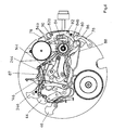
- the display device comprises, on the plate 33, drive means 36 of the disk of the units 28, more particularly illustrated in FIG. 2.
- These training means 36 comprise a trigger mechanism 38 controlled by the wheel 34, a system of regulation 40 released by the trigger mechanism 38, a cog driving the display 42 of the disk of the units 28 and a source of energy formed of a cylinder 43 supplying its energy both to the system 40 and the gearbox 42.
- the trigger mechanism 38 is formed of two levers 44 and 46 pivotally mounted on the plate 33 and a spring 48.
- the lever 44 has two arms 44a and 44b disposed on either side of its pivot point, the arm 44a being provided, at its free end, with a finger 44c arranged to be in engagement with the toothing of the wheel 34.
- the lever 46 is provided with two lifts 46a and 46b intended to cooperate with the control system 40, as will be explained later, and a pad 46c cooperating with the lever 44. It is kept in the rest position, the lifts 46a and 46b retaining the regulation system 40, under the effect of the spring 48.
- the levers 44 and 46 are arranged and cooperate with each other so such as when the wheel 34 raises the lever 44, the arm 44b applies against the stud 46c a force antagonistic to that of the spring 48. This rotates the lever 46, which causes the release of the lifts 46a and 46b of the system of regulation 40.
- the regulation system 40 comprises a multiplier gear train of the speed comprising two mobiles 50 and 52, and a flywheel 54.
- mobile 50 comprises a pinion 50a, which meshes with the barrel 43, and a 50b wheel driving the mobile 52 by its pinion not visible in the drawing.
- This mobile carries a wheel 52b and a cam 52c.
- the wheel 52b meshes with a pinion not visible in the drawing that includes the steering wheel 54.
- the cam 52c is present in the form of a washer provided with a notch 52d. She cooperates with the lift 46a of the lever 46, which is held by the spring 48 in support against the periphery of the cam or engaged in the notch 52d, according to the position of the mobile 52.
- the steering wheel 54 is provided with two arms 54a each carrying a wing 54b, as well as three retaining fingers 54c, arranged radially and arranged to cooperate with lifting 46b.
- the wings 54b each comprise an elastic portion 54d in an arc of a circle concentric with the axis of rotation of the steering wheel, integral with one of the arms 54a by one of its ends, and extending on an angle about 90 °.
- the elastic portions 54d are provided, at their other end, a mass of inertia and braking 54e, intended to cooperate with a drum 56 surrounding the wheel 54 and secured to the plate 33. More precisely, when the wheel 54 turns, the elastic portions 54d of the wings 54b deform elastically under the effect of their mass of inertia 54e, which come rub against the drum 56.
- the drive train of the display 42 comprises a mobile 58, in mesh with the toothing of the cylinder 43 by its pinion, a reference 60, driven by the mobile wheel 58, and driving a wheel 62 units. This last door the disk of the units 28, as well as a trigger cam 64, which is provided with a pin 64a and a finger 64b, whose functions will be specified below.
- the mobiles of the regulation system 40 and the gear train 42 are numbered of so that the wheel 62 rotates 36 ° for a turn of the mobile 52.
- the drive train 42 rotates and moves the wheel 62 forward. of 36 ° and with it the disc of the units 28 of a step, the visible display at the through the window being incremented by one unit.
- Such a structure makes it possible to explain in a simple manner the principle of operation of the device, the functions of regulation and training being separated. It would also be possible to simplify the structure by combining these functions, by meshing the pinion of the mobile 52 with a wheel that would carry the mobile 58, the reference 60 or the wheel 62.
- FIG. 3 represents means of training 136 of the disc of 26. They are, for the most part, similar to the means of training 36 of the units disk, the constituent parts bearing the same reference than those of the training means 36, equipped with a "1" for the number of hundreds.
- the operation of the drive means 136 is, of course, also comparable to that of training facilities 36.
- the cam 64 As soon as the cam 64 has finished moving, it releases the levers 144 and 146, so that the spring 148 causes the lift 146a to bear against the cam 152c. When the latter has completed a complete turn, the lift 146a falls into the notch 152d of the cam 152 and blocks its movement. The tens disk 26 so jumped a step.
- the mobiles of the drive train 142 and the regulation system 140 are numbered so that the tens disk 26 turns from 60 ° to every step, this disc bearing the numbers from 0 to 5.
- the wheel 162 is furthermore provided with a cam 164, comprising a pin 164a and a finger 164b arranged to control the jump of the hour disk 24, as will be explained later.
- the drive of the 24 hours drive is done by means 236, illustrated in Figure 4 and similar to the means 36 and 136, the component parts bearing the same reference than those of the training means 36 and 136, provided with a "2" for number of hundreds.
- the operation of the drive means 236 is, of course, also comparable to that of training facilities 36. In this case, however, the number of mobiles that comprise the regulation system 240 and the gear train 242 drive is higher. This does not change his operation.
- the train of training 242 comprises a mobile 260 arranged concentrically with the wheels 62 and 162, and provided with a pin 260a whose function will be specified later.
- the wheel 262 which carries the disc 24, is in the form of a ring surrounding the center of the movement in an off-center manner, and place by means of a plate 263, fixed to the plate 33 by means of screws represented in the drawing, and pierced with a hole through which the axis of the seconds wheel of timed time as well as the mobiles bearing the hour 14 and minute hands 16.
- the drive means 36, 136 and 236, the drive of the disks 24, 26 and 28 is done without increasing the load of the cylinder ensuring rotation the finishing gear.
- the amplitude of the pendulum is not affected by the jumps of the display disks.
- FIGS 5a and 5b show the opposite faces of a winding mechanism 65 of the barrel springs that includes the movement.
- a winding mechanism 65 of the barrel springs that includes the movement.
- it also raises the barrel 66 for driving the gear train and mentioned above.
- These barrels each comprise a drum identified by the letter a, a shaft b, not shown in the drawing and spring having one end attached to the shaft b, and the other cooperating with the inner wall of the drum by means of a slippery flange.
- a ratchet wheel, identified by the letter c is attached to the shaft b.
- barrels 143 and 243 are coaxial. Their trees 143b and 243b are arranged to be solidary in rotation, and driven together by the wheel to Ratchet 143c.
- FIGS. 1-10 show the crown of winding and setting time 30. It is secured to a rod 67 ensuring the connection between the outside and the inside of the box 10.
- a winding pinion 68 and a gear pinion hour 70 are mounted pivoting on the rod 67, kinematically connected one to the other by a Breguet toothing, and cooperating with a mechanism of winding and setting time, as is customary in this type of movements, but that was not represented to avoid overloading the drawing.
- a crown wheel 72 rotatably mounted on a bridge, not shown drawing, meshes with the winding pinion 68 as well as with the wheel Ratchet 66c of the barrel 66, visible in Figure 5b.
- a train of referrals 74 interconnects the ratchet wheels. More precisely, a first reference 74a is mounted on a square 66d that includes the shaft 66b. he causes a second referral 74b engaged with the ratchet wheel 43c. This last is connected to the ratchet wheel 143c, visible in Figure 5b, by four references 74c to 74f.
- the number of referrals (even or odd) between two ratchet wheels is function of the direction of rotation in which the spring is wound.
- the four barrels 66, 43 are armed, 143 and 243. They can, without further, be fully armed, whatever their state initial, because they are all equipped with a sliding flange.
- the device thus described makes it possible to drive each of the disks of the display of the chronograph by means of a barrel of its own. In this way, it is not taken from the finishing gear, that the energy required for the training wheels of seconds and minutes of time timed and at triggering the device.
- the 24-hour disc performs nine steps and one turn at maximum, it is also possible to store the energy needed for its drive otherwise than in a cylinder, for example in a spring cooperating with a spiral.
- the display device further comprises a mechanism zeroing of the disks 24, 26 and 28, partially illustrated on the Figure 6. It is controlled by the pushers 31 and 32 shown in the figure 1. It cooperates with a control lever 76, part of the mechanism of chronograph, activated by the pusher 31 and which actuates a connecting clutch, in a conventional manner, the finishing gear wheel 34, via a chronograph seconds wheel, not shown in the drawing.
- a first pressure on the pusher 31 starts the measurement and engages the clutch.
- a second press stops the measurement by declutching.
- the records can be set to zero by pressing the pushbutton 32, which control of the means of zeroing that includes the mechanism of chronograph.
- These means comprise, in a conventional manner, a lever of zeroing 78 which actuates a hammer ensuring the zeroing of the wheel chronograph seconds.
- the hooks 84b are arranged in such a way that that they cooperate with the pins 64a, 164a and 260a, to define the position initial discs 24, 26 and 28, as will be explained later.
- the lever command 76 rotates the latch 82 which drives the body of positioning 84 via the fingers 84a, to the position represented in FIG. 6.
- the latch 82 is maintained in its new position by the jumper 90. In this way, the positioning hooks 84b away from the pins. Discs 24, 26 and 28 are no longer retained and can not be rotated, which is what the wheel 34 each of his turns for the disk 28, the other disks being incremented as indicated above.
- a new pressure on the pusher 31 has the effect of moving the clutch, so that the chronograph gear is no longer engaged with the finishing gear train Thus, the measurement is interrupted, the display of the timed time being fixed. The information can therefore be read. It will be noted that this new pressure does not act on organ 84, since is held in the depressed position by the jumper 90.
- the flip-flop 86 raises the levers 44, 144 and 244, the last two by through the lever 87.
- the levers 44, 144 and 244 operate respectively the levers 46, 146 and 246, so that the lifts they comprise release control systems 40, 140 and 240, respectively visible in FIGS. 2, 3 and 4. Consequently, the drive trainings 42, 142 and 242 can rotate under the effect of springs that include barrels 43, 143 and 243.
- the flip-flop 82 causes, via one of the fingers 84a, the positioning member 84, so that the hooks 84b again find on the way pins 64a, 164a and 260a.
- the end of the flip-flop 82 next to the lever 86 engages in a notch that includes last, masked by the wheel 62, so that they remain engaged one with the other, now furthermore the positioning member 84 in the position of blocking disks.
- the pins 64a, 164a and 260a are, of course, arranged in such a way that they cooperate with hooks 84b and that they stop the discs in a position such that the numbers "0" appear in the windows.
- the levers 44, 46, 144, 146, 244 and 246 have cutouts that allow them to be balanced and alleviate. In this way, the forces to be applied to operate the mechanism, and sensitivity to shocks are greatly reduced.
- the display device described above is associated with a mechanism of chronograph.
- the same device could easily be applied to a countdown mechanism, for example, of the type displaying a time descending, or intended at the start of regattas.
- the winding of the barrels is done in one operation. It is also imaginable to provide the movement of a second winding crown, the barrel driving the finishing gear and those resulting in the display of the timed time being armed independently, one by the crown arranged at 3 o'clock, the others by a crown which can be find at 9 o'clock for example. It is also possible to imagine a quartz watch equipped with a chronograph mechanism for example, the energy source of the watch being a battery, while the training of discs would be by means of mechanical energy sources.
- the energy supplied to the display device does not come from the mainspring or the motor providing the drive of the finishing gear.
- the means ensuring the connection between the barrel or barrels and the display disc (s) may have numerous variants, depending on the purpose and the fantasy of the manufacturer.
- the watch as described is advantageously equipped with an indicator of a power reserve, for example that described in the EP application filed on same day as this one on behalf of ETERNA SA, which allows an indication of the time during which the watch can function normally, taking into account counts both the barrel of the basic movement and that of the units.
- the device described above is directly mounted on the plate of the movement. It would also be possible to realize this device on a complementary stage, thus forming a module to fix on the movement of based.
Landscapes
- Physics & Mathematics (AREA)
- General Physics & Mathematics (AREA)
- Measurement Of Unknown Time Intervals (AREA)
- Electromechanical Clocks (AREA)
- Electric Clocks (AREA)
Abstract
Description
La présente invention concerne les dispositifs d'affichage destiné à équiper des mouvements de montres du type comportant un train d'engrenages de finissage et une source d'énergie assurant l'entraínement de ce train d'engrenages. Ce dispositif comporte :
- un disque d'affichage, et
- un rouage d'affichage associé à une fonction complémentaire et dont un mobile porte le disque.
- a display disk, and
- a display gear associated with a complementary function and a mobile carries the disc.
Dans la présente description, on entend par disque une pièce ronde, généralement en plastique ou en métal, qui peut être percée ou non en son centre et porte des indications à afficher.In the present description, a disk is understood to mean a round piece, generally made of plastic or metal, which can be pierced or not in its center and carries indications to display.
L'affichage d'une information au moyen d'un ou plusieurs disques est connu de l'homme du métier. Une des applications les plus fréquentes concerne l'indication du jour et de la date, l'affichage se faisant au moyen de deux disques, lesquels effectuent un saut par jour. Pour assurer ce saut, le mouvement est généralement muni d'un ressort, armé par le rouage de finissage, et qui se détend vers minuit, faisant ainsi passer la date et le jour à l'indication suivante. Il peut également être entraíné dans un premier temps dans un mouvement lent assuré par le rouage de la montre, puis par un saut engendré par un sautoir.Display of information by means of one or more disks is known of the skilled person. One of the most frequent applications concerns indication of the day and date, the display being done by means of two discs, which make a jump a day. To ensure this jump, the movement is usually provided with a spring, armed by the gear of finishing, which relaxes around midnight, thus making the day and the day the following indication. It can also be driven at first in a slow motion ensured by the cogwheel of the watch, then by a jump generated by a jumper.
Lorsque l'information change plus fréquemment qu'une fois par jour, le mécanisme devient plus délicat dans son fonctionnement, l'énergie disponible pour chaque saut étant sensiblement réduite. Ce problème peut être résolu en entraínant les disques en continu, comme proposé dans le document CH 531742. Il en résulte que les chiffres défilent lentement dans un guichet. La lecture de l'information en est rendue difficile, plusieurs chiffres étant apparents pour la même information. When the information changes more frequently than once a day, the mechanism becomes more delicate in its operation, the available energy for each jump being substantially reduced. This problem can be solved by driving the discs continuously, as proposed in the document CH 531742. As a result, the numbers slowly scroll through a window. The It is difficult to read the information, since several figures are apparent for the same information.
Le but de la présente invention est d'assurer un entraínement optimal du ou des disques, même de grande dimension et sans pour autant affecter la bonne marche de la montre.The purpose of the present invention is to ensure optimal training of the discs, even of great size and without affecting the good running of the watch.
A cet effet, le dispositif selon l'invention est caractérisé en ce qu'il comporte, en outre :
- une deuxième source d'énergie reliée cinématiquement au rouage d'affichage, et
- des moyens de commande du rouage agencés de manière à commander son entraínement par la deuxième source d'énergie lorsque l'information à afficher doit être modifiée.
- a second source of energy kinematically connected to the display gear, and
- means for controlling the gear train arranged so as to control its drive by the second power source when the information to be displayed is to be modified.
Ainsi, pratiquement aucune énergie n'est prélevée sur le rouage de finissage, même avec des disques de grand diamètre. Dans une montre mécanique, cela permet d'éviter que l'amplitude du balancier ne soit réduite par l'entraínement du disque. Dans une montre à quartz, l'énergie à délivrer par le moteur ne subit pas de fluctuation, ce qui permet d'augmenter son autonomie sans affecter son fonctionnement.Thus, virtually no energy is taken from the finishing gear, even with large diameter discs. In a mechanical watch, this makes it possible to prevent the amplitude of the pendulum from being reduced by the drive of the disc. In a quartz watch, the energy to be delivered by the motor does not fluctuate, which allows to increase its autonomy without affecting its operation.
De manière avantageuse, la deuxième source d'énergie est mécanique, à l'instar d'un barillet. Le dispositif selon l'invention comporte, en outre des moyens d'armage de cette source d'énergie.Advantageously, the second source of energy is mechanical, at like a barrel. The device according to the invention furthermore comprises means of arming this source of energy.
Un tel dispositif permet d'équiper un mouvement de montre de type chronographe et comprenant:
- un rouage de chronographe dont un mobile effectue un tour par minute et agencé pour porter des moyens d'affichage des secondes du temps chronométré, ainsi que
- un embrayage agencé pour relier ou non le rouage de chronographe audit train d'engrenages et pour commander le départ et l'arrêt de la mesure d'un temps chronométré.
- a chronograph wheel including a mobile performs one revolution per minute and arranged to wear display means seconds timed time, as well as
- a clutch arranged to connect or not the chronograph gear to said gear train and to control the start and stop of the measurement of a timed time.
Le dispositif comporte des moyens d'entraínement pilotés par le rouage de chronographe et commandant l'entraínement du rouage d'affichage par le barillet. The device comprises drive means driven by the wheel of chronograph and commanding drive the display gear by the barrel.
Dans ce dispositif, le rouage d'affichage est agencé de manière à ce que le disque assure l'affichage de temps chronométrés supérieurs ou égaux à la minute.In this device, the display gear is arranged in such a way that the disc ensures the display of timed times greater than or equal to the minute.
Un tel dispositif peut comporter plusieurs disques d'affichage et plusieurs barillets, chaque barillet entraínant un disque.Such a device may include several display disks and several barrels, each barrel driving a disc.
Afin d'assurer un entraínement régulier, le dispositif selon l'invention comporte:
- un système de régulation, agencé pour stabiliser le mouvement de rotation dudit rouage, et
- un mécanisme de déclenchement commandé au moins médiatement par le train d'engrenages de finissage et commandant l'entraínement du disque par le barillet, par l'intermédiaire du rouage d'affichage.
- a control system, arranged to stabilize the rotational movement of said cog, and
- a triggering mechanism controlled at least mediately by the finishing gear train and controlling drive disk by the barrel, through the display train.
Le système de régulation comprend avantageusement un volant d'inertie ainsi qu'une came munie d'un organe de blocage et tournant en synchronisme avec le volant. Le mécanisme de déclenchement comprend un levier agencé de manière à pouvoir occuper :
- une première position dans laquelle il coopère avec l'organe de blocage pour immobiliser le système de régulation,
- une deuxième position dans laquelle il libère la came et laisse tourner le système de régulation, et
- une troisième position dans laquelle il vient en appui contre la came jusqu'à ce qu'il coopère à nouveau avec l'organe de blocage.
- a first position in which it cooperates with the locking member to immobilize the regulation system,
- a second position in which it releases the cam and lets the control system run, and
- a third position in which it bears against the cam until it cooperates again with the locking member.
Dans de tels dispositifs, la mise à zéro des disques par des marteaux, comme cela se fait fréquemment dans les chronographes, peut impliquer une pression exagérée. C'est pourquoi, de manière avantageuse, le dispositif selon l'invention comporte, avantageusement :
- un mécanisme de mise à zéro comprenant un organe de positionnement,
- un repère disposé sur le mobile du rouage d'affichage portant le disque et coopérant avec l'organe de positionnement pour assurer le positionnement du disque, et
- des moyens de commande agencés de manière à ce que, lorsque le mécanisme de mise à zéro est activé, la source d'énergie mécanique entraíne le mobile du rouage d'affichage jusqu'à ce que le repère coopère avec l'organe de positionnement pour positionner le disque.
- a zeroing mechanism comprising a positioning member,
- a mark arranged on the mobile of the display gear carrying the disc and cooperating with the positioning member to ensure the positioning of the disc, and
- control means arranged in such a way that, when the zeroing mechanism is activated, the source of mechanical energy drives the mobile of the display train until the mark cooperates with the positioning member for position the disc.
De la sorte, la mise à zéro peut se faire sans effort pour l'utilisateur, même avec un, voire des disques, de grand diamètre.In this way, the zeroing can be done without effort for the user, even with one or even discs, large diameter.
D'autres avantages et caractéristiques de l'invention ressortiront de la description qui va suivre, faite en regard du dessin annexé, dans lequel:
- La figure 1 représente une montre de type chronographe et munie d'un dispositif d'affichage à disques de temps chronométrés ;
- Les figures 2 à 4 illustrent les mécanismes que comporte le dispositif d'affichage et permettant l'entraínement des disques équipant la montre de la figure 1 ;
- Les figures 5a et 5b montrent la cinématique assurant le remontage des barillets que comporte cette montre ; et
- La figure 6 se rapporte au mécanisme assurant la commande du départ et de l'arrêt d'une mesure, ainsi que la mise à zéro du mécanisme d'affichage par disques.
- FIG. 1 represents a chronograph type watch and provided with a timed disc display device;
- Figures 2 to 4 illustrate the mechanisms that comprises the display device and for driving the discs equipping the watch of Figure 1;
- Figures 5a and 5b show the kinematics ensuring the winding barrels that includes this watch; and
- Figure 6 relates to the mechanism for controlling the start and stop of a measurement, as well as the zeroing of the disk display mechanism.
La montre représentée à la figure 1 comporte une boíte 10 définissant un
logement à l'intérieur duquel se trouve un mouvement. Ce dernier est équipé
d'un mécanisme de chronographe, bien connu en soi, ainsi que d'un dispositif
d'affichage selon l'invention qui sera décrit de manière plus détaillée ci-après.The watch shown in FIG. 1 comprises a
Le mouvement porte un cadran 12, des aiguilles des heures 14, des minutes
16, des secondes 18, de réserve de marche 20, ainsi que des secondes de
temps chronométré 22. Le cadran 12 est muni de trois guichets au travers
desquels apparaissent des disques 24, 26 et 28, affichant respectivement les
heures, les dizaines de minutes et les unités de minutes de temps
chronométré, assurant donc la fonction d'affichage du dispositif selon
l'invention.The movement carries a
Une couronne de remontoir et de mise à l'heure 30 et des poussoirs 31 et 32
sont disposés de manière classique, sur la tranche de la boíte 10. La
couronne 30 permet de fournir l'énergie mécanique nécessaire au
fonctionnement du mouvement, par remontage d'un ressort de barillet,
comme cela sera expliqué plus loin. Les poussoirs 31 et 32 commandent
respectivement le départ et l'arrêt, et la mise à zéro du mécanisme de
chronographe et de son dispositif d'affichage.A winding crown and time setting 30 and
La base du mouvement est formée d'un calibre chronographe tel que celui
commercialisé par la maison ETA SA (Suisse) sous la référence 7750. Ce
mouvement comporte une platine 33, visible sur la figure 2, un rouage de
chronographe et un mécanisme de départ et d'arrêt, qui ne sont que très
partiellement visibles au dessin, étant bien connus de l'homme du métier. Il
comprend, en outre, un barillet, un rouage de finissage, un échappement et
un balancier. De manière classique, le barillet apporte l'énergie au rouage de
finissage, qui la délivre à l'échappement, lequel transforme le mouvement
rotatif du rouage en mouvement alternatif, pour alimenter le balancier.The base of the movement consists of a chronograph caliber such as
marketed by ETA SA (Switzerland) under the reference 7750. This
movement comprises a
Le rouage de chronographe comprend une roue des secondes de temps
chronométré, qui porte l'aiguille des secondes de temps chronométré 22, et
une roue des minutes de temps chronométré 34 entraínée de manière
classique par la roue des secondes de temps chronométré, à raison de un
pas toutes les minutes. Dans les chronographes à affichage par aiguilles, la
roue des minutes 34 porte l'aiguille des minutes de temps chronométré.The chronograph wheel includes a seconds wheel of time
timed, which carries the seconds hand of time timed 22, and
a wheel of minutes of time timed 34 driven so
classic by the seconds wheel of timed time, at a rate of
not every minute. In chronographs with needle displays, the
Le dispositif d'affichage selon l'invention comporte disposé, sur la platine 33,
des moyens d'entraínement 36 du disque des unités 28, plus particulièrement
illustré sur la figure 2. Ces moyens d'entraínement 36 comprennent un
mécanisme de déclenchement 38 commandé par la roue 34, un système de
régulation 40 libéré par le mécanisme de déclenchement 38, un rouage
d'entraínement de l'affichage 42 du disque des unités 28 et une source
d'énergie formée d'un barillet 43 fournissant son énergie à la fois au système
de régulation 40 et au rouage 42.The display device according to the invention comprises, on the
De manière plus précise, le mécanisme de déclenchement 38 est formé de
deux leviers 44 et 46 montés pivotants sur la platine 33 et d'un ressort 48. Le
levier 44 comporte deux bras 44a et 44b disposés de part et d'autre de son
point de pivotement, le bras 44a étant muni, à son extrémité libre, d'un doigt
44c disposé de manière à être en prise avec la denture de la roue 34.More specifically, the
Le levier 46 est muni de deux levées 46a et 46b destinées à coopérer avec le
système de régulation 40, comme cela sera expliqué plus loin, et un plot 46c
coopérant avec le levier 44. Il est maintenu en position de repos, les levées
46a et 46b retenant le système de régulation 40, sous l'effet du ressort 48.
Les leviers 44 et 46 sont agencés et coopèrent l'un avec l'autre de manière
telle que lorsque la roue 34 soulève le levier 44, le bras 44b applique contre le
plot 46c une force antagoniste à celle du ressort 48. Cela fait pivoter le levier
46, ce qui provoque le dégagement des levées 46a et 46b du système de
régulation 40.The
Le système de régulation 40 comprend un train d'engrenages multiplicateur
de la vitesse comportant deux mobiles 50 et 52, et un volant d'inertie 54. Le
mobile 50 comprend un pignon 50a, qui engrène avec le barillet 43, et une
roue 50b entraínant le mobile 52 par son pignon non visible au dessin. Ce
mobile porte une roue 52b et une came 52c. La roue 52b engrène avec un
pignon non visible au dessin que comporte le volant 54. La came 52c se
présente sous forme d'une rondelle munie d'une encoche 52d. Elle coopère
avec la levée 46a du levier 46, qui est maintenue par le ressort 48 en appui
contre le pourtour de la came ou engagée dans l'encoche 52d, selon la
position du mobile 52.The
Le volant 54 est doté de deux bras 54a portant chacun une aile 54b, ainsi que
trois doigts de retenue 54c, disposés radialement et agencés pour coopérer
avec la levée 46b. Les ailes 54b comportent chacune une portion élastique
54d en arc de cercle concentrique à l'axe de rotation du volant, solidaire de
l'un des bras 54a par l'une de ses extrémités, et s'étendant sur un angle
d'environ 90°. Les portions élastiques 54d sont munies, à leur autre extrémité,
d'une masse d'inertie et de freinage 54e, destinée à coopérer avec un
tambour 56 entourant le volant 54 et solidaire de la platine 33. Plus
précisément, lorsque le volant 54 tourne, les portions élastiques 54d des ailes
54b se déforment élastiquement sous l'effet de leur masse d'inertie 54e,
lesquelles viennent frotter contre le tambour 56.The
Le rouage d'entraínement de l'affichage 42 comporte un mobile 58, en prise
avec la denture du barillet 43 par son pignon, un renvoi 60, entraíné par la
roue du mobile 58, et entraínant une roue 62 des unités. Cette dernière porte
le disque des unités 28, ainsi qu'une came de déclenchement 64, laquelle est
munie d'une goupille 64a et d'un doigt 64b, dont les fonctions seront
précisées plus loin.The drive train of the
Les mobiles du système de régulation 40 et du rouage 42 sont nombrés de
manière à ce que la roue 62 tourne de 36° pour un tour du mobile 52.The mobiles of the
Chaque fois que la roue 34 soulève le doigt 44c et entraíne en conséquence
les leviers 44 et 46, les levées 46a et 46b libèrent respectivement la came 52c
et les doigts 54c. De la sorte, le système de régulation 40 se met à tourner à
une vitesse régulée par la friction des masses 54e sur le tambour 56.
Simultanément, le rouage d'entraínement 42 tourne et fait avancer la roue 62
de 36° et avec elle le disque des unités 28 d'un pas, l'affichage visible au
travers du guichet étant incrémenté d'une unité.Whenever the
Dès que la roue 34 libère le doigt 44c, le levier 46 retombe sous l'effet du
ressort 38. La levée 46a vient alors en appui contre la came 52c, sans en
entraver le mouvement de manière significative. La came continue donc à
tourner jusqu'à ce que la levée 46a retombe dans l'encoche 52d. La levée 46b
vient alors bloquer le volant en coopérant avec l'un des doigts 54c. As soon as the
Une telle structure permet d'expliquer de manière simple le principe de
fonctionnement du dispositif, les fonctions de régulation et d'entraínement
étant séparées. Il serait aussi possible de simplifier la structure en combinant
ces fonctions, par engrènement du pignon du mobile 52 avec une roue que
porterait le mobile 58, le renvoi 60 ou la roue 62.Such a structure makes it possible to explain in a simple manner the principle of
operation of the device, the functions of regulation and training
being separated. It would also be possible to simplify the structure by combining
these functions, by meshing the pinion of the mobile 52 with a wheel that
would carry the mobile 58, the
La figure 3 représente des moyens d'entraínement 136 du disque des
dizaines 26. Ils sont, pour l'essentiel, similaires aux moyens d'entraínement
36 du disque des unités, les pièces constitutives portant la même référence
que celles des moyens d'entraínement 36, munies d'un « 1 » pour chiffre des
centaines.FIG. 3 represents means of
Le fonctionnement des moyens d'entraínement 136 est, bien sûr, également
comparable à celui des moyens d'entraínement 36.The operation of the drive means 136 is, of course, also
comparable to that of
Chaque fois que le disque des unités 28 a fait un tour, passant de 9 à 0, et,
avec lui, la came 64, le doigt 64b, visible seulement sur la figure 2, soulève le
doigt 144c du levier 144. Le levier 144 soulève le plot 146c et fait pivoter le
levier 146, armant le ressort 148, alors que les levées 146a et 146b libèrent le
système de régulation 140. Le barillet 143 n'est alors plus retenu. Il entraíne le
volant 154 dont les masses 154e viennent en contact avec le tambour 156,
régulant le mouvement du barillet 143 et du rouage d'entraínement 142 du
disque des dizaines de minutes, dont la roue 162 porte le disque des dizaines
26.Whenever the disk of the
Dès que la came 64 a terminé son déplacement, elle libère les leviers 144 et
146, de telle sorte que le ressort 148 amène la levée 146a en appui contre la
came 152c. Lorsque cette dernière a effectué un tour complet, la levée 146a
retombe dans l'encoche 152d de la came 152 et bloque son mouvement. Le
disque des dizaines 26 a ainsi sauté de un pas.As soon as the
Les mobiles du rouage d'entraínement 142 et du système de régulation 140
sont nombrés de manière à ce que le disque des dizaines 26 tourne de 60° à
chaque pas, ce disque portant les chiffres de 0 à 5. The mobiles of the
La roue 162 est, en outre, munie d'une came 164, comportant une goupille
164a et un doigt 164b agencé pour commander le saut du disque des heures
24, comme cela sera expliqué plus loin.The
L'entraínement du disque des heures 24 se fait par des moyens
d'entraínement 236, illustrés sur la figure 4 et similaires aux moyens
d'entraínement 36 et 136, les pièces constitutives portant la même référence
que celles des moyens d'entraínement 36 et 136, munies d'un « 2 » pour
chiffre des centaines.The drive of the 24 hours drive is done by
Le fonctionnement des moyens d'entraínement 236 est, bien sûr, également
comparable à celui des moyens d'entraínement 36. Dans ce cas toutefois, le
nombre de mobiles que comportent le système de régulation 240 et le rouage
d'entraínement 242 est plus élevé. Cela ne modifie en rien son
fonctionnement.The operation of the drive means 236 is, of course, also
comparable to that of
Ainsi, chaque fois que le disque des dizaines de minutes 26 passe de 5 à 0, le
doigt 164b de la came 164 (figure 3) soulève le doigt 244c, ce qui fait basculer
le levier 244 et, par l'intermédiaire du plot 246c, le levier 246, armant ainsi le
ressort de rappel 248. Les levées 246a et 246b libèrent le système de
régulation 240, de telle sorte que le barillet 243 peut tourner, et avec lui le
rouage d'entraínement 242 du disque des heures. Le rouage d'entraínement
242 comprend un mobile 260 disposé concentriquement aux roues 62 et 162,
et muni d'une goupille 260a dont la fonction sera précisée plus loin.So, every time the disk tens of
La roue 262, qui porte le disque 24, se présente sous forme d'une bague
entourant de manière décentrée le centre du mouvement, et maintenue en
place au moyen d'une plaque 263, fixée à la platine 33 au moyen de vis non
représentées au dessin, et percée d'un trou au travers duquel passe l'axe de
la roue des secondes de temps chronométré ainsi que les mobiles portant les
aiguilles des heures 14 et des minutes 16.The
Grâce aux moyens d'entraínement 36, 136 et 236, l'entraínement des disques
24, 26 et 28 se fait sans augmenter la charge du barillet assurant la rotation
du rouage de finissage. Ainsi, l'amplitude du balancier n'est pas affectée par
les sauts des disques d'affichage.Thanks to the drive means 36, 136 and 236, the drive of the
Les figures 5a et 5b montrent les faces opposées d'un mécanisme de
remontoir 65 des ressorts de barillet que comporte le mouvement. En plus de
l'armage des barillets 43, 143 et 243, il remonte également le barillet 66
destiné à entraíner le rouage de finissage et mentionné plus haut. Ces
barillets comportent chacun un tambour identifié par la lettre a, un arbre b, un
ressort non représenté au dessin et dont une extrémité est fixée à l'arbre b,
l'autre coopérant avec la paroi intérieure du tambour a par l'intermédiaire
d'une bride glissante. Une roue à rochet, identifiée par la lettre c, est fixée à
l'arbre b. Figures 5a and 5b show the opposite faces of a winding
On relèvera que les barillets 143 et 243, respectivement visibles sur les
figures 5b et 5a, sont coaxiaux. Leurs arbres 143b et 243b sont agencés de
manière à être solidaires en rotation, et entraínés ensemble par la roue à
rochet 143c.It will be noted that the
Ces figures montrent également la couronne de remontoir et de mise à l'heure
30. Celle-ci est solidaire d'une tige 67 assurant la liaison entre l'extérieur et
l'intérieur de la boíte 10. Un pignon de remontoir 68 et un pignon de mise à
l'heure 70 sont montés pivotant sur la tige 67, reliés cinématiquement l'un à
l'autre par une denture Breguet, et coopérant avec un mécanisme de
remontoir et de mise à l'heure, comme il est d'usage dans ce type de
mouvements, mais qui n'a pas été représenté pour éviter de surcharger le
dessin.These figures also show the crown of winding and setting
Une roue de couronne 72, montée libre en rotation sur un pont non représenté
au dessin, engrène avec le pignon de remontoir 68 ainsi qu'avec la roue à
rochet 66c du barillet 66, visible sur la figure 5b.A
Avec cette configuration, et pour remonter le barillet 66, il suffit de tourner la
couronne 30, solidaire de la tige 67, lorsqu'elle se trouve ne position
enfoncée. La tige 67 entraíne le pignon coulant 70 et par lui le pignon de
remontoir 68, lequel est relié à la roue de couronne 72 qui arme le ressort de
barillet par l'intermédiaire de la roue à rochet 66c et de l'arbre 66b.
L'entraínement ne se fait que dans un sens, le débrayage s'effectuant entre le
pignon coulant 70 et le pignon de remontoir 68, grâce à la denture Breguet.With this configuration, and to raise the
Un train de renvois 74 relie entre elles les roues à rochet. Plus précisément,
un premier renvoi 74a est monté sur un carré 66d que comporte l'arbre 66b. Il
entraíne un deuxième renvoi 74b en prise avec la roue à rochet 43c. Cette
dernière est reliée à la roue à rochet 143c, visible sur la figure 5b, par quatre
renvois 74c à 74f.A train of
Le nombre de renvois (pair ou impair) compris entre deux roues à rochet est fonction du sens de rotation dans lequel se fait l'armage du ressort.The number of referrals (even or odd) between two ratchet wheels is function of the direction of rotation in which the spring is wound.
Il va de soi que, pour assurer le remontage de tous les barillets, leur roue à rochet coopère avec un cliquet, non représenté au dessin, et qui empêche le ressort contenu dans le tambour de se désarmer.It goes without saying that, to ensure the reassembly of all the barrels, their wheel to ratchet cooperates with a ratchet, not shown in the drawing, and which prevents the spring contained in the drum to disarm.
De la sorte, en tournant la couronne 30, on arme les quatre barillets 66, 43,
143 et 243. Ils peuvent, sans autre, être armés à fond, quel que soit leur état
initial, du fait qu'ils sont tous équipés d'une bride glissante.In this way, by turning the
Le dispositif ainsi décrit permet d'entraíner chacun des disques de l'affichage du chronographe au moyen d'un barillet qui lui est propre. De la sorte, il n'est prélevé, sur le rouage de finissage, que l'énergie nécessaire à l'entraínement des roues des secondes et des minutes de temps chronométré et au déclenchement du dispositif.The device thus described makes it possible to drive each of the disks of the display of the chronograph by means of a barrel of its own. In this way, it is not taken from the finishing gear, that the energy required for the training wheels of seconds and minutes of time timed and at triggering the device.
Dans une variante qui n'a pas été représentée, il serait également possible
d'assurer la fonction des barillets 143 et 243 par un seul barillet. Il suffirait de
remplacer le renvoi 160 par une roue comportant deux secteurs dentés
superposés, l'un destiné à entraíner le disque des dizaines de minutes,
comportant le même nombre de dents que la roue 162, l'autre destiné à
entraíner le disque des heures et comportant le dixième des dents de la roue
262. Dans ce cas, il serait nécessaire de prévoir des moyens de
positionnement des disques 24 et 26, ainsi que des marteaux de remise à
zéro, les roues portant les disques n'étant pas en prise permanente avec le
rouage.In a variant that has not been represented, it would also be possible
to ensure the function of the
Du fait que le disque des heures 24 effectue neuf pas seulement et un tour au maximum, il est aussi possible de stocker l'énergie nécessaire à son entraínement autrement que dans un barillet, par exemple dans un ressort coopérant avec un colimaçon.Because the 24-hour disc performs nine steps and one turn at maximum, it is also possible to store the energy needed for its drive otherwise than in a cylinder, for example in a spring cooperating with a spiral.
Le dispositif d'affichage selon l'invention comporte, en outre, un mécanisme
assurant la mise à zéro des disques 24, 26 et 28, illustré partiellement sur la
figure 6. Il est commandé par les poussoirs 31 et 32 représentés sur la figure
1. Il coopère avec un levier de commande 76, partie du mécanisme de
chronographe, activé par le poussoir 31 et qui actionne un embrayage reliant,
de manière classique, le rouage de finissage à la roue 34, par l'intermédiaire
d'une roue des secondes de chronographe, non représentée au dessin.The display device according to the invention further comprises a mechanism
zeroing of the
De manière classique, une première pression sur le poussoir 31 fait démarrer
la mesure et enclenche l'embrayage. Une deuxième pression arrête la mesure
par débrayage.In a conventional manner, a first pressure on the
Dès que le mécanisme de chronographe est enclenché, son rouage est mis
en mouvement, la roue 34 étant entraínée à raison d'un pas par minute,
engendrant les sauts de disques décrits en référence aux figures 2 à 4.As soon as the chronograph mechanism is engaged, its gear is put
in movement, the
Après que la mesure a été faite, que le temps a été relevé, les disques
peuvent être mis à zéro par une pression sur le poussoir 32, lequel
commande des moyens de mise à zéro que comporte le mécanisme de
chronographe. Ces moyens comprennent, de manière classique, un levier de
mise à zéro 78 qui actionne un marteau assurant la mise à zéro de la roue
des secondes de chronographe.After the measurement has been made, that time has been raised, the records
can be set to zero by pressing the
Le mécanisme de mise à zéro du dispositif selon l'invention comprend :
- un levier de commande 80,
- une bascule de sautoir 82 munie d'un plot de sautoir 82a,
- un organe de positionnement 84 des disques, doté de deux doigts 84a coopérant avec la bascule 82 et deux crochets de positionnement 84b superposés, dont la fonction sera précisée plus loin,
- une bascule de déclenchement 86,
un levier 87 commandé par la bascule 86,un ressort 88, coopérant avec la bascule 86, etun sautoir 90, visible très partiellement sur la figure et coopérant avec leplot 82a pour positionner la bascule 82.
- a
control lever 80, - a
jumper latch 82 provided with ajumper pad 82a, - a positioning
member 84 of the disks, provided with twofingers 84a cooperating with therocker 82 and two superposed positioning hooks 84b, the function of which will be specified below, - a
trigger rocker 86, - a
lever 87 controlled by the flip-flop 86, - a
spring 88, cooperating with therocker 86, and - a
jumper 90, visible very partially in the figure and cooperating with thestud 82a to position the flip-flop 82.
Dans leur position de repos, les crochets 84b sont disposés de manière à ce
qu'ils coopèrent avec les goupilles 64a, 164a et 260a, pour définir la position
initiale des disques 24, 26 et 28, comme cela sera expliqué plus loin.In their rest position, the
Lors du démarrage d'une mesure par une pression sur le poussoir 31, le levier
de commande 76 fait pivoter la bascule 82 qui entraíne l'organe de
positionnement 84 par l'intermédiaire des doigts 84a, jusque dans la position
représentée sur la figure 6. La bascule 82 est maintenue dans sa nouvelle
position par le sautoir 90. De la sorte, les crochets de positionnement 84b
s'écartent des goupilles. Les disques 24, 26 et 28 ne sont plus retenus et
peuvent donc sans autre être entraínés en rotation, ce que fait la roue 34 à
chacun de ses tours pour le disque 28, les autres disques étant incrémentés
comme indiqués plus haut.When starting a measurement by pressing the
Une nouvelle pression sur le poussoir 31 a pour effet de déplacer
l'embrayage, de telle sorte que le rouage de chronographe n'est plus en prise
avec le train d'engrenages de finissage Ainsi, la mesure est interrompue,
l'affichage du temps chronométré étant fixe. L'information peut donc être lue.
On relèvera que cette nouvelle pression n'agit pas sur l'organe 84, puisqu'il
est maintenu en position enfoncée par le sautoir 90.A new pressure on the
Pour remettre les disques à zéro, on exerce une pression sur le poussoir 32
lequel actionne le levier de mise à zéro 78 qui commande, de manière
classique, la mise à zéro du mécanisme de chronographe. Le levier 78 fait
pivoter le levier de commande 80 qui agit simultanément sur les bascules 82
et 86. To reset the disks, press the
La bascule 86 soulève les leviers 44, 144 et 244, les deux derniers par
l'intermédiaire du levier 87. Les leviers 44, 144 et 244 actionnent
respectivement les leviers 46, 146 et 246, de telle sorte que les levées qu'ils
comportent libèrent les systèmes de régulation 40, 140 et 240, respectivement
visibles sur les figures 2, 3 et 4. En conséquence, les rouages d'entraínement
42, 142 et 242 peuvent tourner sous l'effet des ressorts que comportent les
barillets 43, 143 et 243.The flip-
Simultanément, la bascule 82 entraíne, par l'intermédiaire de l'un des doigts
84a, l'organe de positionnement 84, de telle sorte que les crochets 84b se
trouvent à nouveau sur le chemin des goupilles 64a, 164a et 260a. L'extrémité
de la bascule 82 voisine du levier 86 s'engage dans un cran que comporte ce
dernier, masqué par la roue 62, de telle sorte qu'ils restent engagés l'un avec
l'autre, maintenant en outre l'organe de positionnement 84 en position de
blocage des disques. Les goupilles 64a, 164a et 260a sont, bien entendu,
disposées de manière à ce qu'elles coopèrent avec les crochets 84b et
qu'elles arrêtent les disques dans une position telle que les chiffres « 0 »
apparaissent dans les guichets.Simultaneously, the flip-
Pour faire redémarrer une mesure, il suffit de presser sur le poussoir 31. Le
levier 76 entraíne tout d'abord la bascule 82, qui libère le levier 86. Les leviers
46, 146 et 246 ne sont alors plus retenus et basculent respectivement sous
l'effet des ressorts 48, 148 et 248. Les levées qu'ils comportent tombent les
unes dans les découpes 52d, 152d et 252d des cames 52c, 152c et 252c,
alors que les autres se placent en regard des doigts 54c, 154c et 254c avec
lesquelles elles coopèrent. Par ailleurs, l'embrayage que comporte le
mécanisme de chronographe relie le rouage de finissage à la roue des
secondes de temps chronométré. Cette roue de secondes entraíne la roue 34
qui commande les moyens d'entraínement 36 du disque des unités 28,
comme cela a été décrit plus haut. Une nouvelle mesure recommence alors. To restart a measurement, simply press the
On relèvera que, dans le mécanisme décrit, les leviers 44, 46, 144, 146, 244
et 246 présentent des découpes qui permettent de les équilibrer et de les
alléger. De la sorte, les forces à appliquer pour faire fonctionner le
mécanisme, et la sensibilité aux chocs sont considérablement réduites.It will be noted that, in the mechanism described, the
Le dispositif d'affichage décrit ci-dessus est associé à un mécanisme de chronographe. Le même dispositif pourrait facilement être appliqué à un mécanisme de compte à rebours, par exemple, du type affichant un temps décroissant, ou destiné au départ des régates.The display device described above is associated with a mechanism of chronograph. The same device could easily be applied to a countdown mechanism, for example, of the type displaying a time descending, or intended at the start of regattas.
Le remontage des barillets est effectué en une seule opération. Il est aussi imaginable de munir le mouvement d'une deuxième couronne de remontoir, le barillet entraínant le rouage de finissage et ceux entraínant l'affichage du temps chronométré étant armés de manière indépendante, l'un par la couronne disposée à 3 heures, les autres par une couronne qui peut se trouver à 9 heures par exemple. Il est également possible d'imaginer une montre à quartz munie d'un mécanisme de chronographe par exemple, la source d'énergie de la montre étant une pile, alors que l'entraínement des disques se ferait au moyen de sources d'énergie mécanique.The winding of the barrels is done in one operation. It is also imaginable to provide the movement of a second winding crown, the barrel driving the finishing gear and those resulting in the display of the timed time being armed independently, one by the crown arranged at 3 o'clock, the others by a crown which can be find at 9 o'clock for example. It is also possible to imagine a quartz watch equipped with a chronograph mechanism for example, the energy source of the watch being a battery, while the training of discs would be by means of mechanical energy sources.
Il est bien clair que le mouvement pourrait aussi être équipé d'un mécanisme automatique de remontoir assurant ou non l'armage de l'ensemble des barillets.It is quite clear that the movement could also be equipped with a mechanism automatic winding whether or not the arming of all barrels.
Dans tous les cas, toutefois, l'énergie fournie au dispositif d'affichage ne provient pas du ressort de barillet ou du moteur assurant l'entraínement du rouage de finissage.In all cases, however, the energy supplied to the display device does not come from the mainspring or the motor providing the drive of the finishing gear.
Par ailleurs, les moyens assurant la liaison entre le ou les barillets complémentaires et le ou les disques d'affichage peuvent présenter de nombreuses variantes, fonction du but recherché et de la fantaisie du constructeur.Moreover, the means ensuring the connection between the barrel or barrels and the display disc (s) may have numerous variants, depending on the purpose and the fantasy of the manufacturer.
La montre telle que décrite est avantageusement équipée d'un indicateur de réserve de marche, par exemple celui décrit dans la demande EP déposée le même jour que celle-ci au nom de ETERNA SA, qui permet une indication du temps durant lequel la montre peut fonctionner normalement, en prenant en compte à la fois le barillet du mouvement de base et celui des unités.The watch as described is advantageously equipped with an indicator of a power reserve, for example that described in the EP application filed on same day as this one on behalf of ETERNA SA, which allows an indication of the time during which the watch can function normally, taking into account counts both the barrel of the basic movement and that of the units.
Le dispositif décrit ci-dessus est directement monté sur la platine du mouvement. Il serait également possible de réaliser ce dispositif sur une platine complémentaire, formant ainsi un module à fixer sur le mouvement de base.The device described above is directly mounted on the plate of the movement. It would also be possible to realize this device on a complementary stage, thus forming a module to fix on the movement of based.
Ainsi, grâce aux caractéristiques que présente le mouvement selon l'invention, il est possible de réaliser une montre munie d'un affichage assuré par des disques de grandes dimensions, sans pour autant charger le rouage de finissage, en évitant ainsi d'affecter la précision de marche.So, thanks to the features that the movement presents according to the invention, it is possible to make a watch provided with an insured display by large disks, without loading the wheel of finishing, thus avoiding to affect the accuracy of operation.
Claims (10)
Priority Applications (8)
| Application Number | Priority Date | Filing Date | Title |
|---|---|---|---|
| EP03405532A EP1498788A1 (en) | 2003-07-14 | 2003-07-14 | Display device for timepiece |
| AT04738074T ATE480801T1 (en) | 2003-07-14 | 2004-07-08 | DISPLAY DEVICE FOR A WATCH |
| CNB2004800200322A CN100557526C (en) | 2003-07-14 | 2004-07-08 | Display device for timepiece |
| JP2006519740A JP4759515B2 (en) | 2003-07-14 | 2004-07-08 | Wristwatch display device |
| US10/564,548 US7508738B2 (en) | 2003-07-14 | 2004-07-08 | Display device for a watch |
| DE602004029059T DE602004029059D1 (en) | 2003-07-14 | 2004-07-08 | DISPLAY EQUIPMENT FOR ONE CLOCK |
| EP04738074A EP1658531B1 (en) | 2003-07-14 | 2004-07-08 | Display device for timepiece |
| PCT/CH2004/000433 WO2005006087A1 (en) | 2003-07-14 | 2004-07-08 | Display device for a watch |
Applications Claiming Priority (1)
| Application Number | Priority Date | Filing Date | Title |
|---|---|---|---|
| EP03405532A EP1498788A1 (en) | 2003-07-14 | 2003-07-14 | Display device for timepiece |
Publications (1)
| Publication Number | Publication Date |
|---|---|
| EP1498788A1 true EP1498788A1 (en) | 2005-01-19 |
Family
ID=33462278
Family Applications (2)
| Application Number | Title | Priority Date | Filing Date |
|---|---|---|---|
| EP03405532A Withdrawn EP1498788A1 (en) | 2003-07-14 | 2003-07-14 | Display device for timepiece |
| EP04738074A Not-in-force EP1658531B1 (en) | 2003-07-14 | 2004-07-08 | Display device for timepiece |
Family Applications After (1)
| Application Number | Title | Priority Date | Filing Date |
|---|---|---|---|
| EP04738074A Not-in-force EP1658531B1 (en) | 2003-07-14 | 2004-07-08 | Display device for timepiece |
Country Status (7)
| Country | Link |
|---|---|
| US (1) | US7508738B2 (en) |
| EP (2) | EP1498788A1 (en) |
| JP (1) | JP4759515B2 (en) |
| CN (1) | CN100557526C (en) |
| AT (1) | ATE480801T1 (en) |
| DE (1) | DE602004029059D1 (en) |
| WO (1) | WO2005006087A1 (en) |
Cited By (7)
| Publication number | Priority date | Publication date | Assignee | Title |
|---|---|---|---|---|
| EP1857890A2 (en) | 2006-03-30 | 2007-11-21 | Richemont International S.A. | Device for triggering a pulse |
| EP1962155A1 (en) * | 2007-02-22 | 2008-08-27 | ETA SA Manufacture Horlogère Suisse | Chronograph |
| EP1978424A1 (en) * | 2007-04-04 | 2008-10-08 | Montres Journe S.A. | Chronograph |
| EP2897003A3 (en) * | 2014-01-16 | 2016-04-06 | Richemont International S.A. | Movement and mechanical timepiece including a chronograph mechanism |
| EP3382471A1 (en) * | 2017-03-30 | 2018-10-03 | Richemont International S.A. | Watch with digital time display |
| EP3382469A1 (en) * | 2017-03-30 | 2018-10-03 | Richemont International S.A. | Pièce d'horlogerie avec affichage digitale de temps |
| US11675313B2 (en) | 2017-04-18 | 2023-06-13 | Patek Philippe Sa Geneve | Timepiece mechanism |
Families Citing this family (19)
| Publication number | Priority date | Publication date | Assignee | Title |
|---|---|---|---|---|
| EP1498789A1 (en) | 2003-07-14 | 2005-01-19 | Eterna SA | Winding state indicator mechanism for a mechanical timepiece |
| JP4626971B2 (en) * | 2004-12-15 | 2011-02-09 | セイコーインスツル株式会社 | Multifunction timepiece having a fan-shaped hand movement mechanism including a return spring and a fan-shaped hand movement train wheel apparatus |
| JP2006170762A (en) * | 2004-12-15 | 2006-06-29 | Seiko Instruments Inc | Multi-functional timepiece with sectorial hand movement wheel train and sectorial hand movement wheel train device |
| CH707467B1 (en) | 2005-09-13 | 2014-07-15 | Lvmh Swiss Mft Sa | Watch with multifunctional display. |
| DE602007007888D1 (en) * | 2007-04-04 | 2010-09-02 | Eta Sa Mft Horlogere Suisse | Elevator device with unidirectional coupling |
| EP1978420B1 (en) * | 2007-04-04 | 2010-11-10 | ETA SA Manufacture Horlogère Suisse | Gear wheel for a timepiece and device for correction of a display mechanism for a timepiece incorporating such a wheel |
| DE102009019335B4 (en) * | 2009-04-30 | 2011-01-13 | Lange Uhren Gmbh | Clock |
| USD665291S1 (en) * | 2011-03-21 | 2012-08-14 | Lvmh Swiss Manufactures Sa | Watch dial |
| JP6063460B2 (en) * | 2011-06-21 | 2017-01-18 | ロレックス・ソシエテ・アノニムRolex Sa | A timepiece including a winding mechanism and at least one mechanism for modifying at least one display member |
| CN102914959B (en) * | 2012-10-12 | 2014-04-02 | 杭州手表有限公司 | Time-display instant switching mechanism |
| CH707136B1 (en) * | 2012-10-30 | 2016-12-30 | Parmigiani Fleurier S A | Timepiece to indicate the power reserve. |
| USD734173S1 (en) * | 2012-11-30 | 2015-07-14 | Lvmh Swiss Manufactures Sa | Watch |
| USD734175S1 (en) * | 2012-11-30 | 2015-07-14 | Lvmh Swiss Manufactures Sa | Watch |
| RU2525465C1 (en) * | 2013-06-14 | 2014-08-20 | Общество с ограниченной ответственностью "Константин Чайкин" | Positional indication apparatus for clock and clock having positional indication apparatus |
| JP1526107S (en) * | 2014-01-20 | 2015-06-15 | ||
| JP6558761B1 (en) * | 2018-06-19 | 2019-08-14 | セイコーインスツル株式会社 | Escapement machine, watch movement and watch |
| TWD208140S (en) * | 2019-07-22 | 2020-11-11 | 瑞士商拉克雪瑞物品國際公司 | Wristwatch |
| EP3904963B1 (en) | 2020-04-29 | 2022-10-26 | Patek Philippe SA Genève | Timepiece movement comprising an auxiliary mechanism driven by an auxiliary power source |
| CN113189854B (en) * | 2021-04-12 | 2022-02-25 | 天王电子(深圳)有限公司 | Clock display device and watch |
Citations (4)
| Publication number | Priority date | Publication date | Assignee | Title |
|---|---|---|---|---|
| FR1522084A (en) * | 1967-05-09 | 1968-04-19 | Siemens Ag | Time device comprising a mechanical energy accumulator |
| US3675413A (en) * | 1970-07-02 | 1972-07-11 | Schild Sa A | Watch movement having totalizers |
| EP0806712A2 (en) * | 1996-05-09 | 1997-11-12 | Fortis AG | Mechanical watch-movement with incorporated chronometer movement (chronograph movement) |
| WO2002093273A1 (en) * | 2001-05-14 | 2002-11-21 | Eterna Ag Uhrenfabrik | Analogue chronograph comprising a digital display |
Family Cites Families (8)
| Publication number | Priority date | Publication date | Assignee | Title |
|---|---|---|---|---|
| CH1147874A4 (en) * | 1974-08-22 | 1977-05-13 | ||
| JP3081992B2 (en) * | 1996-10-02 | 2000-08-28 | セイコーインスツルメンツ株式会社 | Wristwatch with calendar |
| JPH11202060A (en) * | 1998-01-09 | 1999-07-30 | Citizen Watch Co Ltd | Electronic watch with calendar |
| WO2002077722A1 (en) * | 2001-03-21 | 2002-10-03 | Glashütter Uhrenbetrieb GmbH | Mechanism for actuating a striking work for a timepiece fitted with a timer |
| JP4598363B2 (en) * | 2001-03-21 | 2010-12-15 | グラスヒュッター・ウーレンベトリープ・ゲーエムベーハー | A watch including a mechanism for hoisting a barrel spring at the start of a time-related function |
| ATE390654T1 (en) * | 2002-02-01 | 2008-04-15 | Tag Heuer Sa | DEVICE WITH CLOCK MOVEMENT AND CHRONOGRAPH MODULE |
| JP4296019B2 (en) * | 2003-03-27 | 2009-07-15 | セイコーインスツル株式会社 | Chronograph watch with nulling structure |
| EP1498789A1 (en) | 2003-07-14 | 2005-01-19 | Eterna SA | Winding state indicator mechanism for a mechanical timepiece |
-
2003
- 2003-07-14 EP EP03405532A patent/EP1498788A1/en not_active Withdrawn
-
2004
- 2004-07-08 US US10/564,548 patent/US7508738B2/en not_active Expired - Fee Related
- 2004-07-08 DE DE602004029059T patent/DE602004029059D1/en active Active
- 2004-07-08 JP JP2006519740A patent/JP4759515B2/en not_active Expired - Fee Related
- 2004-07-08 CN CNB2004800200322A patent/CN100557526C/en not_active Expired - Fee Related
- 2004-07-08 AT AT04738074T patent/ATE480801T1/en not_active IP Right Cessation
- 2004-07-08 EP EP04738074A patent/EP1658531B1/en not_active Not-in-force
- 2004-07-08 WO PCT/CH2004/000433 patent/WO2005006087A1/en active Search and Examination
Patent Citations (4)
| Publication number | Priority date | Publication date | Assignee | Title |
|---|---|---|---|---|
| FR1522084A (en) * | 1967-05-09 | 1968-04-19 | Siemens Ag | Time device comprising a mechanical energy accumulator |
| US3675413A (en) * | 1970-07-02 | 1972-07-11 | Schild Sa A | Watch movement having totalizers |
| EP0806712A2 (en) * | 1996-05-09 | 1997-11-12 | Fortis AG | Mechanical watch-movement with incorporated chronometer movement (chronograph movement) |
| WO2002093273A1 (en) * | 2001-05-14 | 2002-11-21 | Eterna Ag Uhrenfabrik | Analogue chronograph comprising a digital display |
Cited By (15)
| Publication number | Priority date | Publication date | Assignee | Title |
|---|---|---|---|---|
| EP1857890A2 (en) | 2006-03-30 | 2007-11-21 | Richemont International S.A. | Device for triggering a pulse |
| EP1857890A3 (en) * | 2006-03-30 | 2011-06-01 | Richemont International S.A. | Device for triggering a pulse |
| EP1962155A1 (en) * | 2007-02-22 | 2008-08-27 | ETA SA Manufacture Horlogère Suisse | Chronograph |
| EP2113817A1 (en) | 2007-02-22 | 2009-11-04 | ETA SA Manufacture Horlogère Suisse | Chronograph |
| US7931399B2 (en) | 2007-02-22 | 2011-04-26 | Eta Sa Manufacture Horlogère Suisse | Chronograph watch |
| EP1978424A1 (en) * | 2007-04-04 | 2008-10-08 | Montres Journe S.A. | Chronograph |
| EP2897003A3 (en) * | 2014-01-16 | 2016-04-06 | Richemont International S.A. | Movement and mechanical timepiece including a chronograph mechanism |
| EP3382471A1 (en) * | 2017-03-30 | 2018-10-03 | Richemont International S.A. | Watch with digital time display |
| EP3382469A1 (en) * | 2017-03-30 | 2018-10-03 | Richemont International S.A. | Pièce d'horlogerie avec affichage digitale de temps |
| CH713660A1 (en) * | 2017-03-30 | 2018-10-15 | Richemont Int Sa | Clock with digital time display. |
| CH713659A1 (en) * | 2017-03-30 | 2018-10-15 | Richemont Int Sa | Clock with digital time display. |
| CN108693762A (en) * | 2017-03-30 | 2018-10-23 | 里什蒙国际股份有限公司 | Clock and watch with digital temporal display |
| US10579018B2 (en) | 2017-03-30 | 2020-03-03 | Richemont International S.A. | Timepiece with digital time display |
| CN108693762B (en) * | 2017-03-30 | 2021-09-07 | 里什蒙国际股份有限公司 | Timepiece with digital time display |
| US11675313B2 (en) | 2017-04-18 | 2023-06-13 | Patek Philippe Sa Geneve | Timepiece mechanism |
Also Published As
| Publication number | Publication date |
|---|---|
| US7508738B2 (en) | 2009-03-24 |
| EP1658531B1 (en) | 2010-09-08 |
| JP4759515B2 (en) | 2011-08-31 |
| US20060215498A1 (en) | 2006-09-28 |
| JP2007533954A (en) | 2007-11-22 |
| EP1658531A1 (en) | 2006-05-24 |
| CN100557526C (en) | 2009-11-04 |
| DE602004029059D1 (en) | 2010-10-21 |
| CN1823309A (en) | 2006-08-23 |
| ATE480801T1 (en) | 2010-09-15 |
| WO2005006087A1 (en) | 2005-01-20 |
| WO2005006087B1 (en) | 2005-03-10 |
Similar Documents
| Publication | Publication Date | Title |
|---|---|---|
| EP1658531B1 (en) | Display device for timepiece | |
| EP3001258B1 (en) | Ringing mechanism with differentiated ringtones | |
| EP2541346B1 (en) | Device for resetting a component indicating a time-related magnitude to a predetermined position | |
| EP3612898A1 (en) | Timepiece mechanism | |
| CH703361A2 (en) | Movement clock having chronograph functions and account-a-down. | |
| EP3945374A1 (en) | Sympathique timepiece assembly | |
| EP3599516B1 (en) | Timepiece retrograde tourbillon or karussel | |
| EP1978424B1 (en) | Chronograph | |
| EP4189494A1 (en) | Sympathetic timekeeping assembly | |
| EP2993533A1 (en) | Timepiece | |
| EP4189489B1 (en) | Time setting method of a watch in a horological unit "sympathique" | |
| FR2921164A1 (en) | Device i.e. sequential display module, for visualizing e.g. watch complication, has mechanical module and masking disk integrated in casing including visualizable parts and units associated to visualizable parts | |
| EP3575886A1 (en) | Timepiece with striking mechanism and safety trigger | |
| CH717702B1 (en) | Nice set of clocks. | |
| CH717703B1 (en) | Nice set of clocks. | |
| CH717700B1 (en) | Nice set of clocks. | |
| CH717701B1 (en) | Nice set of clocks. | |
| CH717699B1 (en) | Nice set of clocks. | |
| WO2002071339A1 (en) | Mechanical watch equipped with weekly cycle indicator | |
| CH717697B1 (en) | Nice set of clocks. | |
| CH717651A2 (en) | Method of winding a sympathetic watch. | |
| EP4189493A1 (en) | Sympathetic timekeeping assembly | |
| CH717654A2 (en) | Process for setting the time of a sympathetic watch. | |
| EP4189490A1 (en) | Sympathetic timekeeping assembly | |
| CH717695A2 (en) | Nice set of clocks. |
Legal Events
| Date | Code | Title | Description |
|---|---|---|---|
| PUAI | Public reference made under article 153(3) epc to a published international application that has entered the european phase |
Free format text: ORIGINAL CODE: 0009012 |
|
| AK | Designated contracting states |
Kind code of ref document: A1 Designated state(s): AT BE BG CH CY CZ DE DK EE ES FI FR GB GR HU IE IT LI LU MC NL PT RO SE SI SK TR |
|
| AX | Request for extension of the european patent |
Extension state: AL LT LV MK |
|
| AKX | Designation fees paid | ||
| REG | Reference to a national code |
Ref country code: DE Ref legal event code: 8566 |
|
| STAA | Information on the status of an ep patent application or granted ep patent |
Free format text: STATUS: THE APPLICATION IS DEEMED TO BE WITHDRAWN |
|
| 18D | Application deemed to be withdrawn |
Effective date: 20050801 |