EP1496800B1 - Real-time navigational aid system for radiography - Google Patents
Real-time navigational aid system for radiography Download PDFInfo
- Publication number
- EP1496800B1 EP1496800B1 EP03745824A EP03745824A EP1496800B1 EP 1496800 B1 EP1496800 B1 EP 1496800B1 EP 03745824 A EP03745824 A EP 03745824A EP 03745824 A EP03745824 A EP 03745824A EP 1496800 B1 EP1496800 B1 EP 1496800B1
- Authority
- EP
- European Patent Office
- Prior art keywords
- volume
- image
- sub
- interest
- region
- Prior art date
- Legal status (The legal status is an assumption and is not a legal conclusion. Google has not performed a legal analysis and makes no representation as to the accuracy of the status listed.)
- Expired - Lifetime
Links
- 238000002601 radiography Methods 0.000 title claims description 31
- 238000000034 method Methods 0.000 claims description 67
- 238000004364 calculation method Methods 0.000 claims description 10
- 239000011159 matrix material Substances 0.000 claims description 7
- 230000008859 change Effects 0.000 claims description 3
- 238000012937 correction Methods 0.000 claims description 3
- 230000006870 function Effects 0.000 description 34
- 238000002583 angiography Methods 0.000 description 17
- 238000003384 imaging method Methods 0.000 description 17
- 210000003484 anatomy Anatomy 0.000 description 8
- 238000011835 investigation Methods 0.000 description 6
- 241001080024 Telles Species 0.000 description 5
- 239000000463 material Substances 0.000 description 5
- 238000011282 treatment Methods 0.000 description 5
- 238000002594 fluoroscopy Methods 0.000 description 4
- 230000008569 process Effects 0.000 description 4
- 238000012545 processing Methods 0.000 description 4
- 238000009877 rendering Methods 0.000 description 4
- 230000001225 therapeutic effect Effects 0.000 description 4
- 230000002792 vascular Effects 0.000 description 4
- 201000008450 Intracranial aneurysm Diseases 0.000 description 3
- 238000012986 modification Methods 0.000 description 3
- 230000004048 modification Effects 0.000 description 3
- 238000005457 optimization Methods 0.000 description 3
- 238000012800 visualization Methods 0.000 description 3
- 238000002591 computed tomography Methods 0.000 description 2
- 238000005516 engineering process Methods 0.000 description 2
- 238000011156 evaluation Methods 0.000 description 2
- 238000002347 injection Methods 0.000 description 2
- 239000007924 injection Substances 0.000 description 2
- 238000002697 interventional radiology Methods 0.000 description 2
- 238000002595 magnetic resonance imaging Methods 0.000 description 2
- 230000003287 optical effect Effects 0.000 description 2
- 210000000056 organ Anatomy 0.000 description 2
- 238000012546 transfer Methods 0.000 description 2
- 238000012285 ultrasound imaging Methods 0.000 description 2
- ZCYVEMRRCGMTRW-UHFFFAOYSA-N 7553-56-2 Chemical compound [I] ZCYVEMRRCGMTRW-UHFFFAOYSA-N 0.000 description 1
- 206010002329 Aneurysm Diseases 0.000 description 1
- 238000012276 Endovascular treatment Methods 0.000 description 1
- 229920000297 Rayon Polymers 0.000 description 1
- 238000004458 analytical method Methods 0.000 description 1
- 230000015572 biosynthetic process Effects 0.000 description 1
- 210000000988 bone and bone Anatomy 0.000 description 1
- 238000013170 computed tomography imaging Methods 0.000 description 1
- 239000002872 contrast media Substances 0.000 description 1
- 238000010586 diagram Methods 0.000 description 1
- 230000004069 differentiation Effects 0.000 description 1
- 238000006073 displacement reaction Methods 0.000 description 1
- 239000003814 drug Substances 0.000 description 1
- 238000003708 edge detection Methods 0.000 description 1
- 230000000694 effects Effects 0.000 description 1
- 238000001839 endoscopy Methods 0.000 description 1
- 230000002452 interceptive effect Effects 0.000 description 1
- 238000007917 intracranial administration Methods 0.000 description 1
- 229910052740 iodine Inorganic materials 0.000 description 1
- 239000011630 iodine Substances 0.000 description 1
- 238000002357 laparoscopic surgery Methods 0.000 description 1
- 230000003902 lesion Effects 0.000 description 1
- 238000013507 mapping Methods 0.000 description 1
- 238000005259 measurement Methods 0.000 description 1
- 239000000203 mixture Substances 0.000 description 1
- 238000011017 operating method Methods 0.000 description 1
- 230000005855 radiation Effects 0.000 description 1
- 239000002964 rayon Substances 0.000 description 1
- 230000009467 reduction Effects 0.000 description 1
- 230000004044 response Effects 0.000 description 1
- 238000003786 synthesis reaction Methods 0.000 description 1
- 230000009466 transformation Effects 0.000 description 1
- 238000000844 transformation Methods 0.000 description 1
- 238000013519 translation Methods 0.000 description 1
- 230000014616 translation Effects 0.000 description 1
Images


Classifications
-
- A—HUMAN NECESSITIES
- A61—MEDICAL OR VETERINARY SCIENCE; HYGIENE
- A61B—DIAGNOSIS; SURGERY; IDENTIFICATION
- A61B6/00—Apparatus or devices for radiation diagnosis; Apparatus or devices for radiation diagnosis combined with radiation therapy equipment
- A61B6/48—Diagnostic techniques
- A61B6/481—Diagnostic techniques involving the use of contrast agents
-
- A—HUMAN NECESSITIES
- A61—MEDICAL OR VETERINARY SCIENCE; HYGIENE
- A61B—DIAGNOSIS; SURGERY; IDENTIFICATION
- A61B6/00—Apparatus or devices for radiation diagnosis; Apparatus or devices for radiation diagnosis combined with radiation therapy equipment
- A61B6/50—Apparatus or devices for radiation diagnosis; Apparatus or devices for radiation diagnosis combined with radiation therapy equipment specially adapted for specific body parts; specially adapted for specific clinical applications
- A61B6/504—Apparatus or devices for radiation diagnosis; Apparatus or devices for radiation diagnosis combined with radiation therapy equipment specially adapted for specific body parts; specially adapted for specific clinical applications for diagnosis of blood vessels, e.g. by angiography
Definitions
- the invention relates to a system for assisting imaging guidance, instruments and materials within a region of interest.
- a volume of the region of interest is a non-limiting object volume of representation concerning the external shape of the object or the internal form of the object, obtained from any imaging technique making it possible to produce such volumes.
- Real-time live images are real-time animated images obtained by any imaging technique capable of producing these images.
- Instruments and materials are instrumentation that can be visualized by the imaging technique that produces the real-time active images.
- the radioscopies in superposition mode and said "Road-Map" perform a radio-guidance assistance according to the plane of the reference image, that is to say the projection plane of the image determined by the position of the hoop , the position of the anatomical region of interest that depends on the position of the examination table, and the magnification and scale of the reference image that depends on the value of the field of view and the Geometric magnification determined by the ratio of the focal length of the X-ray source to the recording means, and the distance from the X-ray source to the object to be radiographed.
- These two modes of radioscopy have several disadvantages.
- any modification of the reference image plane, the position of the anatomical region of interest, the enlargement or the scale of image the operator must proceed either to the acquisition and storage of a new reference image in the context of the radioscopy in superposition mode, or to the generation of a new reference subtracted image within the framework of the radioscopy mode called "Road-Map".
- Road-map superimposing radioscopies offer radio guidance assistance based on flat reference images, fixed in the plane reference, requiring to be acquired or generated a priori. These reference images do not give information on the third dimension of the region of interest, which represents a limiting and restrictive character of the radio guidance assistance by these two modes of radioscopy.
- the document DE 10047314 A1 discloses a navigation method and a radiography device for obtaining virtual contrast for enhanced angiography.
- the preambles of claims 1 and 12 are based on its contents.
- An object of the invention is to provide an improved navigation system with respect to all or part of this problem.
- the method recalculates in real time, without further intervention, the volumes and volume projection images displayed.
- the user therefore always has in real time an optimal visualization, either of the volume and / or of the projection image of the volume of the region of interest such that the "sees" the radiography device, and this without any additional graphing or scopie is necessary, reducing by the same amount the radiation dose emitted during the intervention, either the resulting volume and / or the resulting image of the superimposition or the subtraction, respectively, in a plane section. determined in the volume and / or the volume projection image, of the corresponding parameterization image, which enables the user to optimize in real time the guidance of his instrumentation, the control of the progress of the his technical gesture and the evaluation of the result of the technical gesture.
- a radiography device as described in claim 12 is also provided.
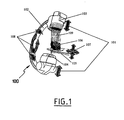
- a radiography apparatus 100 comprises a hoop 102 and a support 105, here a table, able to receive an object 106, here the head of a patient intended to be radiographed by the radiography apparatus 100 for intervention at the level of an anatomical region of interest, for example.
- the arch 102 in substantially semicircular shape, comprises at one of its ends an X-ray source 104 and at its other end an X-ray sensor 103 capable of acquiring X-ray images and radioscopic images of the region of interest previously positioned in the X-ray cone 109 emitted by the source 104.
- the useful surface of the sensor 103 is opposite the X-ray source 104.
- the X-ray source 104 and the X-ray sensor 103 are able to move toward or away from each other (shown by the arrows 101).
- the relative positions of the X-ray source 104 and the X-ray sensor 103 are materialized by the distance separating them and represented by the focal length parameter (DF) that the apparatus Angiography 100 continuously records in storage means provided for this purpose (not shown).
- DF focal length parameter
- the relative positions of the X-ray source 104 and the region of interest of the object 106 to be radiographed are materialized by the distance which separates them and represented by the object distance parameter (OD) that the apparatus of Angiography 100 permanently records in storage means provided for this purpose (not shown).
- OD object distance parameter
- the field of view is defined by a parameter (FOV) permanently recorded by the angiography apparatus 100 in storage means provided for this purpose (not shown).
- FOV field of view
- the arch 102 is able to move according to the three rotations of the space shown diagrammatically by the arrows 108.
- This spatial position of the arch is represented by the angular coordinates ( ⁇ , ⁇ , ⁇ ) that continuously records the X-ray apparatus 100 in storage means provided for this purpose (not shown).
- the support table 105 is able to move according to the three translations of the space shown schematically by the set of arrows 107. As before, the position of the support table 105 is represented by rectangular coordinates (x, y, z) that the X-ray apparatus 100 records in permanence in storage means provided for this purpose (not shown).
- the position of the origin O of the reference frame of the radiography apparatus 100 is the isocenter represented by the point of intersection of the virtual lines passing through the axis of the X-ray tube forming the X-ray source 104, and the center of the image intensifier comprising the X-ray sensor 103 for two different positions of the hoop 102.
- the spatial coordinates of the hoop 102 are determined by angular coordinates ( ⁇ , ⁇ , ⁇ ).
- the position of the origin of the reference frame of the hoop 102 of the radiography apparatus 100 is the isocenter O.
- the spatial coordinates of the table 105 are determined by rectangular coordinates (x, y, z).
- the field of view (FOV) parameter of the X-ray apparatus 100 depends on the characteristics of the equipment of the X-ray apparatus 100 used, and preferably takes one of the values 33, 22, 17, and 13 cm.
- the reference value of the field of view is that taken into account for the realization of the image acquisition series by rotational angiography.
- the focal length parameter (DF) and the object distance parameter (OD) are length characteristics on the axis of the X-ray tube forming the X-ray source 104 passing through the center of the X-ray image intensifier. 103.
- the reference values of the focal lengths (DF) and object (DO) are those taken into account for the realization of the series of images acquisition by rotational angiography.
- the “entries” column of the table indicates all the data provided by the X-ray apparatus 100 that are accessible to the method according to the disclosure.
- the method according to the disclosure is schematized in the "treatment” column of the table of the figure 2 .
- the "outputs" column of the said table of the figure 2 represents the information that the process provides back to the user.
- the number of images obtained per degree of angle is determined by the rotation speed of the hoop 102 and the image acquisition frequency (FREQ).
- the total number of images obtained is determined by the number of images per degree of angles and the extent of the rotation of the hoop 102 (ANG-MAX).
- the native angular images II 1-i of projection different incidences of the region of interest of the object 106 resulting from the series of acquisition by rotational angiography are viewed perpendicularly to the plane of rotation of the hoop 102, under several incidences depending on the position of the hoop 102 during the rotation for acquiring the images from different angles of view.
- the set of angular native images II 1-i are transformed into axial native images IX 1-i .
- the native angular images II 1-i of projection of different incidences of the object 106 containing the region of interest, obtained by rotation of the arch 102 are recalculated and reconstructed in axial projection IX 1-i in order to obtain a stack of images along a predetermined axis in order to be reconstructed in three dimensions taking into account all the images IX 1-i or a part of these images after selection of an image stack I 1-k ( k being between 1 to j) corresponding to the region of interest to be the subject of an intervention.
- These steps are performed directly by the X-ray apparatus 100.
- All of these axial native images I 1-k rotational angiography is recovered by the method according to the invention (arrow 1; figure 2 ) in storage means of the radiography apparatus 100 where they are stored. Then, these native axial images serve as input data I1 1-k (arrow 2) to a reconstruction function F1.
- This function F1 allows reconstruction in three dimensions so as to obtain a volume of the region of interest of the object 106 from these input data axial images I1 1-k .
- the volume V1 thus obtained and corresponding to the output data of function F1 (arrow 3) is composed of a set of several voxels.
- the voxel is the unit of volume corresponding to the smallest element of a three-dimensional space to which individual characteristics such as color or intensity can be attributed.
- the term voxel is the acronym for volume cell element (or volume cell element ).
- the three-dimensional space is thus cut into elementary cubes and each object is described by the cubes that compose it.
- the volume V1 is a three-dimensional matrix of 1 voxels per h voxels per p voxels. Obtaining this three-dimensional matrix representing volume V1 is the culmination of step a) of the method according to the invention.
- steps b), c) and d) of the process according to the invention are preferably carried out intraoperatively, while the operator is working on the patient.
- the second step of the method according to the invention corresponds to step b) and consists of the phases b F2 ) and b F3 ) respectively corresponding to the functions F2 and F3 of the method that we will now describe.
- the input data used by the function F2 are on the one hand the three-dimensional matrix of the volume V1 (arrow 4) and on the other hand the rectangular coordinates (x, y, z) ( arrow 7), at the instant t, of the support table 105, read (arrow 5) in the storage means of these rectangular coordinates of the X-ray apparatus 100, illustrating the position of the table 105 at the instant t, as well as the angular coordinates ( ⁇ , ⁇ , ⁇ ) (arrow 7), at the moment t, of the arch 102, read (arrow 6) in the storage means of these angular coordinates of the radiography apparatus 100, illustrating the position of the arch 102 at time t.
- a last input data item is optionally supplied to the function F2 (arrow 8) and corresponds to the dimensions (n x ' n y' , n z ' ) of a volume V2 calculated and reconstructed by the function F2 from the volume V1 .
- These parameters n x ' , n y' , n z ' are variable and determined at the instant t by the user himself.
- these parameters n x ' , n y' , n z ' are expressed in voxel and can be between 1 voxel and a maximum number of voxels allowing calculation and reconstruction of the volume V2 from the whole volume V1.
- the calculated minimum volume V2min corresponds to the minimum values of (n x ' , n y' , n z ' ) (i.e. 1 voxel) and the calculated maximum volume V2max corresponds to the maximum possible values of (n x ' , n y' , n z ' ) making it possible to reconstruct the volume V2 from the volume V1 in its entirety.
- the function F2 calculates and reconstructs, from the volume V1 at time t, the volume V2 as well as, if appropriate, a projection image IP2 of the volume V2 corresponding to the coordinates (x, y, z) of the table 105 and ( ⁇ , ⁇ , ⁇ ) of the hoop 102, and the dimensions (n x ' , n y' , n z ' ) of the volume V2.
- the volume data V2 and the possible projection image IP2 of the volume V2 are available (the volume V2 being between a volume V2min and a volume V2max corresponding to the extreme values of n x ' , n y' , n z ' ) (arrow 9) .
- the volume V2 thus obtained is therefore a volume reconstructed from the volume VI and parameterized at time t by the coordinates (x, y, z) of the support table 105 and ( ⁇ , ⁇ , ⁇ ) of the hoop 102, as well as the dimensions (n x ' , n y' , n z ' ) ranging from 1 voxel determining a volume V2min of a reconstructed voxel from volume V1 to the maximum dimensions determining a reconstructed volume V2max from the whole volume V1.
- the projection image IP2 is calculated by projection along the axis of incidence, on a plane perpendicular to this axis, of the volume V2 thus determined.
- the position of the region of interest of the object 106 to be X-rayed with respect to the X-ray source 104 and the X-ray sensor 103 at time t determines the geometric magnification parameter (DF / OD), at the moment t, defined by the ratio between the focal length (DF) at time t, and the object distance (DO) at time t.
- DF / OD geometric magnification parameter
- the function F3 calculates, at time t, the geometric magnification and the scaling of the volume V2 reconstructed from the volume V1, as well as the projection image IP2 volume V2.
- the function F3 applies the geometric function of magnification, in this case the geometric function of Thales taking into account that the ratio between a dimension in the volume V2 reconstructed from the volume V1 of the region of interest of the radiographed object 106 or a dimension on the projection image IP2 of the volume V2, and the dimension at the corresponding location in the region of interest, is equal to the ratio between the focal length (DF) and the object distance (OD) of the X-ray source 104 at the corresponding location in the region of interest of the object 106 where the dimension is taken into account.
- FOV field of view
- DO object
- DF focal length
- volume V3 is ultimately a calculated volume and reconstructed from the volume V1 and parameterized at time t by the coordinates (x, y, z) of the table 105, and ( ⁇ , ⁇ , ⁇ ) of the hoop 102, the parameters of geometric enlargement and of scaling of the field of view (FOV), the object distance (OD) and the focal length (DF), as well as the dimensions (n x ' , n y' , n z ' ) ranging from 1 voxel determining a volume V3min of a reconstructed voxel from the volume V1, to the maximum dimensions determining a reconstructed volume V3max from the entire volume V1.
- the calculated volume V3 is in the form of a three-dimensional
- the method according to the invention can transfer the volume V3 and / or the projection image IP3 for display (arrow 15) on suitable display means. to be consulted at the instant t by the user.
- This allows the user to see at time t, on display means, a volume VR of the region of interest (volume V3 transmitted) and / or the projection image IP (transmitted image IP3) of the volume of the region of interest, corresponding to the relative position of the support 105, the hoop 102, and the values of the field of view (FOV), object distance (OD), focal length (DF) and dimensions (n x ' , n y' , n z ' ) at this instant t.
- FOV field of view
- OD object distance
- DF focal length
- dimensions n x ' , n y' , n z '
- the user operator of the method according to the invention can introduce into the region of interest one or more instruments 110 ( Figure 4a ) which he wishes, at the instant t, to know the exact position.
- the operator uses the radiography apparatus to capture a scopie image (IS) (arrow 16) at time t, while the arch 102 is at the angular coordinates ( ⁇ , ⁇ , ⁇ ), the support table 105 at the rectangular coordinates (x, y, z), and the sensor 103 and the X-ray source 104 positioned to have the field of view (FOV), the object distance (OD) and the focal length (DF).
- the image of scopie IS1 thus captured is read (arrow 17), at this moment t, in means for storing the data of the optical image of the radiography apparatus 100, accessible to the method according to the invention.
- the data corresponding to this scopie image IS1 serve as input data (arrow 18) during step c) of the method according to the invention to a function F4.
- This function F4 thus comprises, as input data, the volume V3 and / or the projection image IP3 of volume V3 previously calculated (arrow 19) and the image of scopie IS1, captured and read at time t in the means for storing the data of the optical image of the radiography apparatus 100.
- the function F4 performs the superposition or the subtraction, at time t, in the volume V3 in a determined plane section and / or on the IP3 projection image of the previously calculated volume V3, of the image of scopie IS1 corresponding settings (arrow 16) relative to the coordinates (x, y, z) of the table 105 and ( ⁇ , ⁇ , ⁇ ) of the hoop 102 as well as field of view (FOV), object distance (OD) and focal length (DF) values.
- FOV field of view
- OD object distance
- DF focal length
- the function F4 superimposes or subtracts in the volume V3 in a given plane section and / or on the projection image IP3 of the volume V3, the image of scopie IS1, and / or calculates a projection image IP4 of a volume V4 resulting from the superposition or the subtraction in the volume V3 in a given plane section of the image of scopie IS1, the projection taking place in a plane parallel to the plane of the image of scopie IS1 and in a direction perpendicular to said scopie image IS1.
- the function F4 outputs (arrow 20) the volume V4 and / or the projection image IP4 resulting from the superposition or subtraction previously described.
- the method according to the invention can transfer the volume V4 (ie a VRS volume) and / or the projection image IP4 (ie an IR image) so as to display them (arrow 21) on display means capable of being consulted, at the instant t, by the user.
- This allows the user to see at time t, on display means, the VRS volume of the region of interest and / or the IR projection image of the volume of the region of interest corresponding to the relative position of the support 105, the hoop 102, and the values of the field of view (FOV), object distance (OD), focal length (DF), and dimensions (n x ' , n y' , n z) ' ) at this moment t.
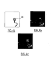
- the user knows the exact position according to the predetermined parameters at this instant t, instruments 110 within the region of interest considered, as illustrated in FIG. Figures 4a to 4c .
- figure 4a is illustrated an image of scopie IS1 taken at a time t, visualizing the instruments and materials 110.
- figure 4b present an IP3 projection image of an arterial structure comprising an intracranial aneurysm, calculated as previously described, corresponding to the parameters (x, y, z), ( ⁇ , ⁇ , ⁇ ), (FOV), (DO), (DF) ) and (n x ' , n y' , n z ' ) associated with the image scopie IS1 of the figure 4a .
- FIG 4c is illustrated an IRS projection image resulting from the superposition carried out by the function F4 during step c) of the method according to the invention where the image of scopie IS1 of the figure 4a was superimposed on the IP3 projection image of the figure 4b illustrating how the operator checks and controls the positioning of his instrumentation 110 during an intervention on an aneurysm as illustrated.
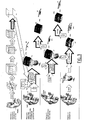
- the Figures 5 and 6 represent the result of calculating an IP projection image according to different positions of the hoop 102.
- the first line of images of the figure 5 corresponds to a variation of the angle ⁇ of the hoop 102 respectively at -90 °, -45 °, 0 °, 45 ° and 90 ° while the other angles ⁇ , ⁇ remain unchanged at 0 °.
- the second line of images illustrates a similar variation of the angle ⁇ whereas ⁇ , ⁇ are fixed at 0 °.
- ⁇ , ⁇ are fixed at 0 ° and ⁇ varies.
- the figure 6 illustrates for fixed spatial coordinates ( ⁇ , ⁇ , ⁇ ) and (x, y, z) the calculation of an IP projection image according to different values for n z ' (n x' and n y ' being unchanged), respectively Voxels, voxels, 45 voxels, 60 voxels and 75 voxels.
- the programming language used is the Java language. It is designed by the association of several software modules or plug-ins (or even plugins according to the Anglo-Saxon term) adding each of the features as we have described them previously.
- they allow basic functions for processing images of any format including the DICOM format used in radiology. These functions are reading, displaying, editing, analyzing, processing, saving and printing such images. They make it possible to calculate statistics on a pixel, or a voxel, or on a defined area by selection. Distance and angle measurements can be made. They can also perform processing on densities and support most of the standard imaging functions such as contrast modification, edge detection or median filters. They can further perform geometric transformations such as magnification, scaling, rotation; all the functions of analysis and previous treatments being usable at any magnification.
- each function specific to the method according to the invention is performed by a dedicated plug-in.
- a plug-in allows the calculation and reconstruction of orthogonal slices with respect to a given axis of a volume or a region of interest.
- Another plug-in deals with the computation and reconstruction of a volume, and its associated projection image, by performing a volume rendering and by rendering said rendering on any set of voxels and / or on any stack of cuts.
- This plug-in allows volume reconstruction along a specific axis.
- the volume can be rotated, enlarged, or reduced.
- the interpolation of the volume rendering is a trilinear interpolation, known per se, except for the end sections of the stack and / or the end voxels of the voxel set where this trilinear interpolation is impossible. .
- nearest-neighbor interpolation known per se, is used instead of trilinear interpolation.
- Another plug-in makes it possible to project along an axis, as an example in maximum projection intensity (M.I.P). This makes it possible to calculate the projection image IP3 of the volume V3, for example.
- M.I.P maximum projection intensity
- the method according to the invention described above uses the various plug-ins previously cited to calculate the projection image of a volume.
- Three-dimensional imaging acquired by rotational angiography allows a better understanding of the real anatomy of a lesion, an organ, or a part of an organ by allowing the visualization of this structure from every angle of view. required. His interest is essentially diagnostic. Therapeutically, its interest is limited to the optimization of the relevant angles of view, either before treatment to define a priori a therapeutic strategy or after treatment to evaluate the therapeutic result.
- the use of three-dimensional reference imaging in per-therapeutics is a new concept, never elaborated until now in projection imaging, for, at any moment during the intervention, to adapt and adjust its therapeutic decisions and strategies, to assist and control its technical gesture and to evaluate the therapeutic results.
- a framework for applying the method according to the invention is described according to a projection imaging technique from an angiography apparatus, for the investigation and the endovascular treatment of an intracranial aneurysm.
- the region of interest is represented by the afferent intracranial arterial vascular network carrying an intracranial aneurysm.
- Images that reconstruct the volume of the three-dimensional region of interest can be come from images or volumes previously reworked, without being exhaustive, the reconstructions of images or volumes from all the techniques mentioned above.
- the imaging technique producing the real-time active images and the one allowing the acquisition for the reconstruction of the volume of the region of interest in three dimensions can be without being exhaustive either the same technique or different techniques and thus requiring the identification of the volume of the region of interest according to a repository either internal or external to the subject on which depends the region of interest.
Landscapes
- Health & Medical Sciences (AREA)
- Life Sciences & Earth Sciences (AREA)
- Medical Informatics (AREA)
- Engineering & Computer Science (AREA)
- Radiology & Medical Imaging (AREA)
- Molecular Biology (AREA)
- Biophysics (AREA)
- Nuclear Medicine, Radiotherapy & Molecular Imaging (AREA)
- Optics & Photonics (AREA)
- Pathology (AREA)
- Physics & Mathematics (AREA)
- Biomedical Technology (AREA)
- Heart & Thoracic Surgery (AREA)
- High Energy & Nuclear Physics (AREA)
- Surgery (AREA)
- Animal Behavior & Ethology (AREA)
- General Health & Medical Sciences (AREA)
- Public Health (AREA)
- Veterinary Medicine (AREA)
- Vascular Medicine (AREA)
- Dentistry (AREA)
- Oral & Maxillofacial Surgery (AREA)
- Apparatus For Radiation Diagnosis (AREA)
Description
L'invention concerne un système d'aide au guidage sous imagerie, d'instruments et de matériels au sein d'une région d'intérêt.The invention relates to a system for assisting imaging guidance, instruments and materials within a region of interest.
Un volume de la région d'intérêt est un volume objet sans caractère limitatif de représentation concernant la forme externe de l'objet ou la forme interne de l'objet, obtenu à partir de toute technique d'imagerie permettant de produire de tels volumes.A volume of the region of interest is a non-limiting object volume of representation concerning the external shape of the object or the internal form of the object, obtained from any imaging technique making it possible to produce such volumes.
Des images actives temps réel sont des images animées temps réel obtenues par toute technique d'imagerie capable de produire ces images.Real-time live images are real-time animated images obtained by any imaging technique capable of producing these images.
Des instruments et matériels sont des instrumentations visualisables par la technique d'imagerie produisant les images actives temps réel.Instruments and materials are instrumentation that can be visualized by the imaging technique that produces the real-time active images.
Actuellement, les procédures de radiologie interventionnelle assistées sous imagerie par angiographie, par exemple, pour l'investigation ou le traitement d'une région anatomique d'intérêt sont actuellement réalisées à l'aide d'un système d'aide au radioguidage basé sur des images de référence planes selon 2 modes possibles de radioscopie :
- La radioscopie en mode superposition consiste à superposer une image plane de référence, soustraite ou non soustraite, de contraste inversé ou non inversé, préalablement acquise et mémorisée, sur l'image radioscopique avec possibilité de changer le pourcentage de mélange de l'image de référence.
- La radioscopie en mode dit "Road-Map" est une radioscopie soustraite. Une image plane soustraite est générée durant la radioscopie pour servir de masque aux radioscopies suivantes. Dans le domaine du vasculaire, une injection de produit de contraste pendant la génération de l'image soustraite durant la radioscopie réalise une cartographie vasculaire qui servira de masque de référence aux radioscopies suivantes. L'image opacifiée des vaisseaux est soustraite de l'image radioscopique active avec possibilité de mélanger en proportion variable un fond anatomique à l'image soustraite.
- Superposition radioscopy consists in superimposing a reference plane image, subtracted or not subtracted, of inverted or non-inverted contrast, previously acquired and stored, on the radioscopic image with the possibility of changing the percentage of mixing of the reference image.
- "Road-Map" mode radioscopy is a subtracted radioscopy. A subtracted plane image is generated during the fluoroscopy to mask the subsequent fluoroscopy. In the vascular field, an injection of contrast material during the generation of the subtracted image during the fluoroscopy carries out a vascular mapping which will serve as a reference mask for the subsequent radioscopies. The opacified image of the vessels is subtracted from the active radioscopic image with the possibility of mixing, in variable proportion, an anatomical background with the subtracted image.
Les radioscopies en mode superposition et dit "Road-Map" réalisent une assistance au radio-guidage selon le plan de l'image de référence, c'est à dire le plan de projection de l'image déterminé par la position de l'arceau, la position de la région anatomique d'intérêt qui dépend de la position de la table d'examen, et selon l'agrandissement et l'échelle de l'image de référence qui dépendent de la valeur du champ de vue et de l'agrandissement géométrique déterminé par le rapport entre la distance focale de la source de rayons X aux moyens d'enregistrement, et, la distance de la source de rayons X à l'objet à radiographier. Ces deux modes de radioscopie présentent plusieurs inconvénients.The radioscopies in superposition mode and said "Road-Map" perform a radio-guidance assistance according to the plane of the reference image, that is to say the projection plane of the image determined by the position of the hoop , the position of the anatomical region of interest that depends on the position of the examination table, and the magnification and scale of the reference image that depends on the value of the field of view and the Geometric magnification determined by the ratio of the focal length of the X-ray source to the recording means, and the distance from the X-ray source to the object to be radiographed. These two modes of radioscopy have several disadvantages.
D'une part, à toute modification du plan de l'image de référence, de la position de la région anatomique d'intérêt, de l'agrandissement ou de l'échelle de l'image, l'opérateur doit procéder soit à l'acquisition et la mémorisation d'une nouvelle image de référence dans le cadre de la radioscopie en mode superposition, soit à la génération d'une nouvelle image soustraite de référence dans le cadre de la radioscopie en mode dit "Road-Map". Ces manipulations itératives ont pour conséquence d'allonger les temps d'intervention et d'irradiation, et d'augmenter les quantités de produit de contraste injectées chez le patient.On the one hand, any modification of the reference image plane, the position of the anatomical region of interest, the enlargement or the scale of image, the operator must proceed either to the acquisition and storage of a new reference image in the context of the radioscopy in superposition mode, or to the generation of a new reference subtracted image within the framework of the radioscopy mode called "Road-Map". These iterative manipulations have the consequence of lengthening the intervention and irradiation times, and increasing the quantities of contrast product injected into the patient.
D'autre part, en cours d'intervention, lors de l'acquisition ou de la génération de nouvelles images de référence soustraites dans les cadres respectifs de la radioscopie en mode superposition avec image de référence soustraite et de la radioscopie en mode dit "Road-Map", il y a une perte d'information concernant la visualisation des instruments et du matériel de traitement radio-opaques en place par leur soustraction avec l'image de référence. Dans le cadre de la radioscopie en mode superposition avec image de référence non soustraite, la définition et la différenciation des structures anatomiques adjacentes dépendent de la différence de radio-opacité entre ces structures et posent problème lorsque la radio-opacité de celles-ci sont peu différentes ou pas assez différentes telle une structure vasculaire, canalaire ou cavitaire opacifiée par rapport à une structure osseuse adjacente.On the other hand, during the intervention, during the acquisition or the generation of new reference images subtracted in the respective frames of the radioscopy in superimposition mode with subtracted reference image and the radioscopy mode called "Road -Map ", there is a loss of information regarding the visualization of instruments and radiopaque processing equipment in place by their subtraction with the reference image. In the context of superimposed radioscopy with non-subtracted reference image, the definition and differentiation of adjacent anatomical structures depends on the difference in radiopacity between these structures and is problematic when the radiopacity of these structures is low. different or not different enough such a vascular structure, ductal or opacified cavity relative to an adjacent bone structure.
Les radioscopies en mode superposition et dit "Road-Map" offrent une assistance au radioguidage basée sur des images de référence planes, figées dans le plan de référence, nécessitant d'être acquises ou générées à priori. Ces images de référence ne donnent pas d'information sur la troisième dimension de la région d'intérêt, ce qui représente un caractère limitatif et restrictif de l'assistance au radioguidage par ces deux modes de radioscopie.Road-map superimposing radioscopies offer radio guidance assistance based on flat reference images, fixed in the plane reference, requiring to be acquired or generated a priori. These reference images do not give information on the third dimension of the region of interest, which represents a limiting and restrictive character of the radio guidance assistance by these two modes of radioscopy.
Le document
Un but de l'invention est de fournir un système de navigation amélioré par rapport à tout ou partie de cette problématique.An object of the invention is to provide an improved navigation system with respect to all or part of this problem.
A cet effet, on prévoit, selon l'invention, un procédé de navigation tel que décrit dans la revendication 1.For this purpose, it is provided, according to the invention, a method of navigation as described in
Ainsi, dès que l'un des paramètres cités est modifié, le procédé recalcule en temps réel sans autre intervention les volumes et images de projection de volume affichés. L'utilisateur a donc toujours en temps réel une visualisation optimale, soit du volume et/ou de l'image de projection du volume de la région d'intérêt telle que la « voit » le dispositif de radiographie, et ce sans qu'aucun moyen de graphie ou scopie supplémentaire soit nécessaire, réduisant d'autant la dose de rayonnement émis en cours d'intervention, soit du volume résultant et/ou de l'image résultante de la superposition ou de la soustraction, respectivement, selon une coupe plane déterminée dans le volume et/ou sur l'image de projection de volume, de l'image de scopie de paramétrage correspondant, ce qui permet à l'utilisateur d'optimiser en temps réel le guidage de son instrumentation, le contrôle du déroulement de son geste technique et l'évaluation du résultat du geste technique.Thus, as soon as one of the parameters mentioned is modified, the method recalculates in real time, without further intervention, the volumes and volume projection images displayed. The user therefore always has in real time an optimal visualization, either of the volume and / or of the projection image of the volume of the region of interest such that the "sees" the radiography device, and this without any additional graphing or scopie is necessary, reducing by the same amount the radiation dose emitted during the intervention, either the resulting volume and / or the resulting image of the superimposition or the subtraction, respectively, in a plane section. determined in the volume and / or the volume projection image, of the corresponding parameterization image, which enables the user to optimize in real time the guidance of his instrumentation, the control of the progress of the his technical gesture and the evaluation of the result of the technical gesture.
Avantageusement mais facultativement, le procédé présente l'une au moins des caractéristiques supplémentaires suivantes :
- l'étape b) comporte des sous-étapes de :
- b1) lecture dans des moyens de mémorisation du dispositif de radiographie d'une position (x,y,z) du support, d'une position (α,β,γ) de la source et des moyens d'enregistrement, du champ de vue (FOV), des distances focale (DF) et objet (DO); et,
- b2) calcul de l'image de projection et/ou du sous-volume en fonction des paramètres ainsi lus.
- l'étape b) comporte des sous étapes de :
- b1) lecture dans des moyens de mémorisation du dispositif de radiographie d'une position (x,y,z) du support, d'une position (α,β,γ) de la source et des moyens d'enregistrement ;
- b2) calcul en fonction des ces positions d'un sous-volume V2 du volume V1 ;
- b3) lecture dans les moyens de mémorisation du dispositif de radiographie du champ de vue (FOV), des distances focale (DF) et objet (DO) ;
- b4) calcul en fonction du champ de vue (FOV), des distances focale (DF) et objet (DO) d'un volume corrigé V3 du sous-volume V2 ; et,
- b5) calcul éventuel de l'image de projection à partir du volume corrigé V3.
- le volume corrigé V3 est calculé suivant un agrandissement géométrique et une mise à l'échelle en fonction du champ de vue (FOV) et des distances focale (DF) et objet (DO).
- lors de l'étape b2), une image de projection IP2 du sous volume V2 est, en outre, calculée en fonction desdites positions.
- lors de l'étape b5), l'image de projection IP3 est une image corrigée de l'image de projection IP2 en fonction du champ de vue (FOV), des distance focale (DF) et objet (DO).
- le calcul de la correction s'effectue par application d'une fonction géométrique d'agrandissement.
- le calcul du sous-volume V2 comporte des étapes de :
- i) détermination dans le volume V1 d'un axe d'incidence en fonction de la position (α,β,γ) de la source et des moyens d'enregistrement relativement à un référentiel du dispositif de radiographie dont une origine est un isocentre dudit dispositif de radiographie ;
- ii) détermination dans le volume V1 d'un centre du sous-volume V2 en fonction de la position (x,y,z) du support ; et,
- iii) calcul et reconstruction du sous-volume V2 à partir du volume V1 suivant un axe de reconstruction parallèle à l'axe d'incidence.
- le sous-volume V2 présente des dimensions nx' par ny' par nz' définies par un opérateur.
- l'étape a) comporte des sous-étapes de :
- a1) acquisition d'une pile de coupes de la région d'intérêt ; et,
- a2) reconstruction du volume V1 sous la forme d'une matrice tridimensionnelle de voxels.
- l'étape c) comporte des sous-étapes de :
- c1) Lecture de l'image de scopie dans des moyens de mémorisation du dispositif de radiographie de l'image de scopie ;
- c2) Superposition ou soustraction à l'image de projection et/ou du sous-volume selon une coupe plane déterminée de l'image de scopie.
- step b) comprises sub-steps of:
- b1) reading in storage means of the X-ray device of a position (x, y, z) of the support, a position (α, β, γ) of the source and of the recording means, of the field of view (FOV), focal lengths (DF) and object (OD); and,
- b2) calculating the projection image and / or the sub-volume according to the parameters thus read.
- step b) comprises sub-steps of:
- b1) reading in storage means of the radiography device of a position (x, y, z) of the support, a position (α, β, γ) of the source and the recording means;
- b2) calculating according to these positions a sub-volume V2 of the volume V1;
- b3) reading in the storage means of the field of view radiography device (FOV), the focal length (DF) and object (DO);
- b4) calculation according to the field of view (FOV), the focal lengths (DF) and object (DO) of a corrected volume V3 of the subvolume V2; and,
- b5) possible calculation of the projection image from the corrected volume V3.
- the corrected volume V3 is calculated according to a geometric magnification and a scaling according to the field of view (FOV) and the focal length (DF) and object (DO).
- in step b2), a projection image IP2 of the sub-volume V2 is further calculated according to said positions.
- in step b5), the projection image IP3 is a corrected image of the projection image IP2 as a function of the field of view (FOV), the focal length (DF) and the object (DO).
- the correction is calculated by applying a geometric magnification function.
- the subvolume V2 calculation comprises steps of:
- i) determination in the volume V1 of an incidence axis as a function of the position (α, β, γ) of the source and of the recording means relative to a reference frame of the radiography device whose origin is an isocenter of said radiography device;
- ii) determining in the volume V1 a center of the sub-volume V2 as a function of the position (x, y, z) of the support; and,
- iii) calculating and reconstructing the sub-volume V2 from the volume V1 along a reconstruction axis parallel to the incidence axis.
- the subvolume V2 has dimensions n x ' by n y' by n z ' defined by an operator.
- step a) comprises sub-steps of:
- a1) acquiring a stack of sections of the region of interest; and,
- a2) reconstruction of the volume V1 in the form of a three-dimensional matrix of voxels.
- step c) comprises sub-steps of:
- c1) Reading the image of fluoroscopy in memory means of the radiography device of the fluoroscopic image;
- c2) Superposition or subtraction to the projection image and / or the sub-volume according to a specific planar section of the fluoroscopic image.
On prévoit aussi, selon l'invention, un dispositif de radiographie tel que décrit dans la revendication 12.According to the invention, a radiography device as described in
D'autres caractéristiques et avantages de l'invention apparaîtront lors de la description ci-après d'un mode de réalisation préféré. Aux dessins annexés :
- La
figure 1 représente schématiquement le positionnement d'une région d'intérêt au sein d'un appareil de radiographie de type angiographie mettant en oeuvre le procédé de la divulgation, - La
figure 2 est un logigramme du procédé selon la divulgation, - La
figure 3 est un logigramme détaillé des différentes fonctions de lafigure 2 , - Les
figures 4a, 4b, 4c sont un exemple illustratif du résultat du procédé selon la divulgation, - Les
figures 5 et 6 sont des exemples illustratifs du résultat du calcul de l'image de projection en M.I.P. (Maximum Intensity Projection ou projection à maximum d'intensité) à partir du volume initial de la région d'intérêt selon le procédé de la divulgation sous différentes positions de l'appareil de radiographie par rapport à la région d'intérêt.
- The
figure 1 schematically represents the positioning of a region of interest in an angiography-type radiography apparatus implementing the method of disclosure, - The
figure 2 is a logic diagram of the process according to the disclosure, - The
figure 3 is a detailed logigram of the different functions of thefigure 2 , - The
Figures 4a, 4b, 4c are an illustrative example of the result of the method according to the disclosure, - The
Figures 5 and 6 are illustrative examples of the result of the calculation of the MIP (Maximum Intensity Projection) projection image from the initial volume of the region of interest according to the method of disclosure at different positions of the X-ray apparatus with respect to the region of interest.
En référence à la
Le champ de vue, dont les valeurs possibles sont prédéterminées en fonction de l'équipement radiologique 100, est défini par un paramètre (FOV) qu'enregistre en permanence l'appareil d'angiographie 100 dans des moyens de mémorisation prévus à cet effet (non représentés).The field of view, the possible values of which are predetermined according to the
D'autre part, l'arceau 102 est capable de se déplacer selon les trois rotations de l'espace schématisées par les flèches 108. Cette position spatiale de l'arceau est représentée par les coordonnées angulaires (α, β, γ) qu'enregistre en permanence l'appareil de radiographie 100 dans des moyens de mémorisation prévus à cet effet (non représentés). La table support 105 est apte à se déplacer selon les trois translations de l'espace schématisées par l'ensemble de flèches 107. Comme précédemment, la position de la table support 105 est représentée par des coordonnées rectangulaires (x,y,z) que l'appareil de radiographie 100 enregistre en permanence dans des moyens de mémorisation prévus à cet effet (non représentés).On the other hand, the arch 102 is able to move according to the three rotations of the space shown diagrammatically by the
L'ensemble de ces paramètres, coordonnées rectangulaires (x,y,z) de la table 105, coordonnées angulaires (α, β, γ) de l'arceau 102, distance focale (DF), distance objet (DO) et champ de vue (FOV), que l'opérateur, en cours d'intervention, modifie de manière quasi-permanente, vont piloter le procédé selon l'invention que nous allons maintenant décrire.The set of these parameters, rectangular coordinates (x, y, z) of the table 105, angular coordinates (α, β, γ) of the
La position de l'origine O du référentiel de l'appareil de radiographie 100 est l'isocentre représenté par le point d'intersection des droites virtuelles passant par l'axe du tube radiogène formant la source de rayons X 104, et le centre de l'amplificateur de brillance comportant le capteur de rayons X 103 pour deux positions différentes de l'arceau 102.The position of the origin O of the reference frame of the
Les coordonnées spatiales de l'arceau 102 sont déterminées par des coordonnées angulaires (α, β, γ). La position de l'origine du référentiel de l'arceau 102 de l'appareil de radiographie 100 est l'isocentre O. L'origine des coordonnées angulaires (a = 0°, p = 0°, y = 0°) est définie par la position verticale à 0 degré d'angle d'inclinaison latérale droite et gauche, et d'inclinaison longitudinale antérieure et postérieure (ou cranio-caudale ou caudo-craniale) de l'arceau 102 par rapport au support table 105 apte à recevoir l'objet à radiographier 106.The spatial coordinates of the
Les coordonnées spatiales de la table 105 sont déterminées par des coordonnées rectangulaires (x,y,z). La position de l'origine 0' du référentiel de la table 105 de l'appareil de radiographie 100 et l'origine des coordonnées rectangulaires (x = 0, y = 0, z = 0) sont déterminées par la position de la table 105 lorsque la région d'intérêt de l'objet 106 est positionnée dans l'isocentre O pour la réalisation de la série d'acquisition des images par angiographie rotationnelle décrite ultérieurement.The spatial coordinates of the table 105 are determined by rectangular coordinates (x, y, z). The position of the origin 0 'of the reference frame of the table 105 of the
Le paramètre champ de vue (FOV) de l'appareil de radiographie 100, dépend des caractéristiques de l'équipement de l'appareil de radiographie 100 utilisé, et prend, de manière préférentielle, l'une des valeurs 33, 22, 17, et 13 cm. La valeur de référence du champ de vue est celle prise en compte pour la réalisation de la série d'acquisition des images par angiographie rotationnelle.The field of view (FOV) parameter of the
Le paramètre distance focale (DF) et le paramètre distance objet (DO) sont des caractéristiques de longueur sur l'axe du tube radiogène formant la source de rayons X 104 passant par le centre de l'amplificateur de brillance comportant le capteur de rayons X 103. Les valeurs de référence des distances focale (DF) et objet (DO) sont celles prise en compte pour la réalisation de la série d'acquisition des images par angiographie rotationnelle.The focal length parameter (DF) and the object distance parameter (OD) are length characteristics on the axis of the X-ray tube forming the
En référence aux
La première étape du procédé selon l'invention correspond à l'étape a) qui se déroule préalablement à l'intervention elle-même et consiste en l'acquisition d'un certain nombre d'images de la région d'intérêt considérée et d'en reconstruire un volume tridimensionnel V1. Pour cela, le procédé utilise notamment la méthode de l'angiographie rotationnelle. Le principe d'une telle angiographie consiste en la réalisation d'une série d'images planes natives de projection de l'objet 106 contenant la région d'intérêt visualisée sous plusieurs incidences suivant la rotation de l'arceau, en vue d'être reconstruite en trois dimensions. La région d'intérêt devant faire l'objet d'une telle reconstruction est positionnée dans l'isocentre, comme illustré à la
- différents paramètres prédéfinis avant le lancement de l'arceau que sont la fréquence d'acquisition des images (FREQ), le champ de vue (FOV), la distance focale (DF), la distance objet (DO) de la région d'intérêt de l'objet à radiographier 106 par rapport à la source de rayons
X 104, l'étendue de la rotation de l'arceau 102 représentée par l'angle maximum de rotation (ANG-MAX), la vitesse de rotation de l'arceau 102 ainsi que les coordonnées rectangulaires (x,y,z) de latable support 105 de telle façon que la région d'intérêt de l'objet 106 à radiographier soit positionnée dans l'isocentre afin d'éviter qu'elle ne sorte du champ d'images visualisées lors de la rotation de l'arceau 102, - des paramètres variables pendant la rotation de l'arceau 102 pour l'acquisition de la série d'images que sont les coordonnées angulaires (α,β,γ) de l'arceau 102 qui varient dans le plan de rotation.
- various pre-defined parameters before the launch of the hoop, namely the image acquisition frequency (FREQ), the field of view (FOV), the focal length (DF), the object distance (OD) of the region of interest of the object to be radiographed 106 with respect to the
x-ray source 104, the extent of the rotation of the arch 102 represented by the maximum angle of rotation (ANG-MAX), the rotational speed of the arch 102 as well as the rectangular coordinates (x, y, z) of the support table 105 so that the region of interest of theobject 106 to be radiographed is positioned in the isocenter to prevent it from coming out of the field of images visualized during the rotation of the arch 102, - variable parameters during the rotation of the arch 102 for the acquisition of the series of images that are the angular coordinates (α, β, γ) of the
hoop 102 which vary in the plane of rotation.
Le nombre d'images obtenues par degré d'angle est déterminé par la vitesse de rotation de l'arceau 102 et la fréquence d'acquisition des images (FREQ). Le nombre i total d'images obtenues est déterminé par le nombre d'images par degré d'angles et l'étendue de la rotation de l'arceau 102 (ANG-MAX). Les images natives angulaires II1-i de projection d'incidences différentes de la région d'intérêt de l'objet 106 résultant de la série d'acquisition par angiographie rotationnelle sont visualisées perpendiculairement au plan de rotation de l'arceau 102, sous plusieurs incidences selon la position de l'arceau 102 au cours de la rotation permettant l'acquisition des images sous des angles de vue différents.The number of images obtained per degree of angle is determined by the rotation speed of the
Ensuite, dans une sous-étape suivante, l'ensemble des images natives angulaires II1-i sont transformées en images natives axiales IX1-i. Les images natives angulaires II1-i, de projection d'incidences différentes de l'objet 106 contenant la région d'intérêt, obtenues par rotation de l'arceau 102 sont recalculées et reconstruites en projection axiale IX1-i afin d'obtenir un empilement d'images selon un axe prédéterminé en vue d'être reconstruites en trois dimensions en prenant en compte la totalité des images IX1-i ou une partie de ces images après sélection d'une pile d'images I1-k (k étant compris entre 1 à j) correspondant à la région d'intérêt devant faire l'objet d'une intervention. Ces étapes sont effectuées directement par l'appareil de radiographie 100.Then, in a following substep, the set of angular native images II 1-i are transformed into axial native images IX 1-i . The native angular images II 1-i , of projection of different incidences of the
L'ensemble de ces images natives axiales I1-k d'angiographie rotationnelle est récupéré par le procédé selon l'invention (flèche 1;
Le voxel est l'unité de volume correspondant au plus petit élément d'un espace tridimensionnel auquel on peut attribuer des caractéristiques individuelles, telles que la couleur ou l'intensité. Le terme voxel est l'acronyme anglais de volume cell element (ou élément cellule de volume). L'espace tridimensionnel est ainsi découpé en cubes élémentaires et chaque objet est décrit par les cubes qui le compose. Ainsi, le volume V1 est une matrice tridimensionnelle de 1 voxels par h voxels par p voxels. L'obtention de cette matrice tridimensionnelle représentant le volume V1 constitue l'aboutissement de l'étape a) du procédé selon l'invention.The voxel is the unit of volume corresponding to the smallest element of a three-dimensional space to which individual characteristics such as color or intensity can be attributed. The term voxel is the acronym for volume cell element (or volume cell element ). The three-dimensional space is thus cut into elementary cubes and each object is described by the cubes that compose it. Thus, the volume V1 is a three-dimensional matrix of 1 voxels per h voxels per p voxels. Obtaining this three-dimensional matrix representing volume V1 is the culmination of step a) of the method according to the invention.
Les étapes suivantes b), c) et d) du procédé selon l'invention s'effectuent préférentiellement en per-opératoire, alors que l'opérateur est en train d'intervenir sur le patient.The following steps b), c) and d) of the process according to the invention are preferably carried out intraoperatively, while the operator is working on the patient.
La deuxième étape du procédé selon l'invention correspond à l'étape b) et est constituée des phases bF2) et bF3) correspondant respectivement aux fonctions F2 et F3 du procédé que nous allons maintenant décrire.The second step of the method according to the invention corresponds to step b) and consists of the phases b F2 ) and b F3 ) respectively corresponding to the functions F2 and F3 of the method that we will now describe.
Au cours de la phase bF2), les données d'entrée utilisées par la fonction F2 sont d'une part la matrice tridimensionnelle du volume V1 (flèche 4) et d'autre part les coordonnées rectangulaires (x,y,z) (flèche 7), à l'instant t, de la table support 105, lues (flèche 5) dans les moyens de mémorisation de ces coordonnées rectangulaires de l'appareil de radiographie 100, illustrant la position de la table 105 à l'instant t, ainsi que les coordonnées angulaires (α, β, γ) (flèche 7), à l'instant t, de l'arceau 102, lues (flèche 6) dans les moyens de mémorisation de ces coordonnées angulaires de l'appareil de radiographie 100, illustrant la position de l'arceau 102 à l'instant t. Une dernière donnée d'entrée est éventuellement fournie à la fonction F2 (flèche 8) et correspond aux dimensions (nx' ny', nz') d'un volume V2 calculé et reconstruit par la fonction F2 à partir du volume V1. Ces paramètres nx', ny', nz' sont variables et déterminés, à l'instant t, par l'utilisateur lui-même. De préférence, ces paramètres nx', ny', nz' sont exprimés en voxel et peuvent être compris entre 1 voxel et un nombre maximum de voxels permettant le calcul et la reconstruction du volume V2 à partir de tout le volume V1. Par la suite, le volume minimal V2min calculé correspond aux valeurs minimales de (nx', ny', nz') (c'est-à-dire 1 voxel) et le volume maximal V2max calculé correspond aux valeurs maximales possibles de (nx', ny', nz') permettant de reconstruire le volume V2 à partir du volume V1 en entier.During the phase b F2 ), the input data used by the function F2 are on the one hand the three-dimensional matrix of the volume V1 (arrow 4) and on the other hand the rectangular coordinates (x, y, z) ( arrow 7), at the instant t, of the support table 105, read (arrow 5) in the storage means of these rectangular coordinates of the
A partir de l'ensemble de ces données d'entrée, la fonction F2 calcule et reconstruit, à partir du volume V1 à l'instant t, le volume V2 ainsi qu'éventuellement, une image de projection IP2 du volume V2 correspondant aux coordonnées (x,y,z) de la table 105 et (α, β, γ) de l'arceau 102, et aux dimensions (nx', ny', nz') du volume V2. En sortie de la fonction F2, les données du volume V2 et de l'éventuelle image de projection IP2 du volume V2 sont disponibles (le volume V2 étant compris entre un volume V2min et un volume V2max correspondant aux valeurs extrêmes de nx', ny', nz') (flèche 9). Le volume V2 ainsi obtenu est donc un volume reconstruit à partir du volume VI et paramétré, à l'instant t, par les coordonnées (x,y,z) de la table support 105 et (α, β, γ) de l'arceau 102, ainsi que les dimensions (nx', ny', nz') allant de 1 voxel déterminant un volume V2min d'un voxel reconstruit à partir du volume V1, aux dimensions maximales déterminant un volume V2max reconstruit à partir de tout le volume V1.From all of these input data, the function F2 calculates and reconstructs, from the volume V1 at time t, the volume V2 as well as, if appropriate, a projection image IP2 of the volume V2 corresponding to the coordinates (x, y, z) of the table 105 and (α, β, γ) of the
Le calcul et la reconstruction du volume V2 à partir du volume V1 sont effectués, préférentiellement, selon l'algorithme suivant :
- détermination dans le volume V1 de l'axe d'incidence en fonction de (α, β, γ) relativement au référentiel de la
salle d'angiographie 100 dont l'origine est l'isocentre, et, de la position du centre du volume V2 en fonction de (x, y, z) relativement au référentiel du support table 105 dont l'origine est déterminée par la position de la table lors de la série d'acquisition des images devant servir à la reconstruction du volume V1 de la région d'intérêt de l'objet 106, comme indiqué précédemment dans les définitions ; - initialisation par l'opérateur de préférence ou détermination des dimensions nx' ny' nz' en nombre de voxels du volume V2; et,
- calcul et reconstruction à partir du volume V1, du volume V2 par interpolation trilinéaire entre les voxels d'un ensemble de voxels à considérer du volume V1, dont le centre à été précédemment déterminé, de dimension (nx', ny', nz') voxels, suivant un axe de reconstruction représenté par l'axe d'incidence précédemment déterminé.
- determination in the volume V1 of the incidence axis as a function of (α, β, γ) relative to the reference of the
angiography room 100 whose origin is the isocenter, and, from the position of the center of the volume V2 as a function of (x, y, z) relative to the reference frame of thetable support 105 whose origin is determined by the position of the table during the acquisition series of the images to be used to reconstruct the volume V1 of the region of interest of theobject 106, as indicated previously in the definitions; - initialization by the operator preferably or determination of the dimensions n x ' n y' n z ' in number of voxels of the volume V2; and,
- calculation and reconstruction from volume V1, volume V2 by trilinear interpolation between voxels of a set of voxels to be considered of volume V1, whose center has been previously determined, of dimension (n x ' , n y' , n z ' ) voxels, along a reconstruction axis represented by the axis of incidence previously determined.
L'image de projection IP2 est calculée par projection selon l'axe d'incidence, sur un plan perpendiculaire à cet axe, du volume V2 ainsi déterminé.The projection image IP2 is calculated by projection along the axis of incidence, on a plane perpendicular to this axis, of the volume V2 thus determined.
Le volume V2 ainsi obtenu se présente sous la forme d'une matrice tridimensionnelle de nx' voxels par ny' voxels par nz' voxels. Ce volume V2 et l'image de projection IP2 de ce volume V2 servent de données d'entrée pour une fonction F3 constituant principalement la phase bF3) suivante de l'étape b) du procédé selon l'invention (flèche 10). Trois autres paramètres servent de données d'entrée (flèche 13) à cette fonction F3 :
- le paramètre (FOV) (flèche 13), à l'instant t, du champ de vue, lu (flèche 11) dans les moyens de mémorisation de ce paramètre de l'appareil de radiographie 100,
- le paramètre (DF) (flèche 13), à l'instant t, de la distance focale, lu (flèche 12) dans les moyens de mémorisation de ce paramètre de l'appareil de radiographie 100, et
- la paramètre (DO) (flèche 13), à l'instant t, de la distance objet, lu (flèche 12) dans des moyens de mémorisation de ce paramètre de l'appareil de radiographie 100.
- the parameter (FOV) (arrow 13), at the instant t, of the field of view, read (arrow 11) in the storage means of this parameter of the
radiography apparatus 100, - the parameter (DF) (arrow 13), at the instant t, of the focal distance, read (arrow 12) in the storage means of this parameter of the
radiography apparatus 100, and - the parameter (DO) (arrow 13), at the instant t, of the object distance, read (arrow 12) in the storage means of this parameter of the
radiography apparatus 100.
La position de la région d'intérêt de l'objet 106 à radiographier par rapport à la source de rayons X 104 et au capteur de rayons X 103 à l'instant t détermine le paramètre agrandissement géométrique (DF/DO), à l'instant t, défini par le rapport entre la distance focale (DF) à l'instant t, et la distance objet (DO) à l'instant t.The position of the region of interest of the
A partir de ces différentes données d'entrée la fonction F3 calcule, à l'instant t, l'agrandissement géométrique et la mise à l'échelle du volume V2 reconstruit à partir du volume V1, ainsi que de l'image de projection IP2 du volume V2. Pour cela, selon les paramètres champ de vue(FOV), distances objet(DO) et focale (DF), la fonction F3 applique la fonction géométrique d'agrandissement, en l'occurrence la fonction géométrique de Thalès tenant compte que le rapport entre une dimension dans le volume V2 reconstruit à partir du volume V1 de la région d'intérêt de l'objet 106 radiographié ou une dimension sur l'image de projection IP2 du volume V2, et, la dimension à l'endroit correspondant dans la région d'intérêt, est égal au rapport entre la distance focale (DF) et la distance objet (DO) de la source de rayons X 104 à l'endroit correspondant dans la région d'intérêt de l'objet 106 où la dimension est prise en compte.From these different input data the function F3 calculates, at time t, the geometric magnification and the scaling of the volume V2 reconstructed from the volume V1, as well as the projection image IP2 volume V2. For this, according to the field of view (FOV), object (DO) and focal length (DF), the function F3 applies the geometric function of magnification, in this case the geometric function of Thales taking into account that the ratio between a dimension in the volume V2 reconstructed from the volume V1 of the region of interest of the radiographed
En sortie (flèche 14), la fonction F3 fournit un volume corrigé V3 du volume V2 et une image de projection IP3 du volume V3 ou une image de projection corrigée IP3 de l'image de projection IP2 du volume V2. Le volume V3 est, in fine, un volume calculé et reconstruit à partir du volume V1 et paramétré à l'instant t par les coordonnées (x, y, z) de la table 105, et (α, β, γ) de l'arceau 102, les paramètres d'agrandissement géométrique et de mise à l'échelle du champ de vue (FOV), de la distance objet (DO) et de la distance focale (DF), ainsi que les dimensions (nx', ny', nz') allant de 1 voxel déterminant un volume V3min d'un voxel reconstruit à partir du volume V1, aux dimensions maximales déterminant un volume V3max reconstruit à partir de tout le volume V1. Comme pour les volumes V1 et V2 précédents, le volume V3 calculé se présente sous la forme d'une matrice tridimensionnelle de voxels.At the output (arrow 14), the function F3 provides a corrected volume V3 of the volume V2 and a projection image IP3 of the volume V3 or a corrected projection image IP3 of the projection image IP2 of the volume V2. Volume V3 is ultimately a calculated volume and reconstructed from the volume V1 and parameterized at time t by the coordinates (x, y, z) of the table 105, and (α, β, γ) of the
Une fois le volume V3 et l'image de projection IP3 du volume V3 calculés, le procédé selon l'invention peut transférer le volume V3 et/ou l'image de projection IP3 pour affichage (flèche 15) sur des moyens d'affichage aptes à être consultés à l'instant t par l'utilisateur. Ceci permet à l'utilisateur de voir à l'instant t, sur des moyens d'affichage, un volume VR de la région d'intérêt (volume V3 transmis) et/ou l'image de projection IP (image IP3 transmise) du volume de la région d'intérêt, correspondant à la position relative du support 105, de l'arceau 102, et aux valeurs des paramètres champ de vue (FOV), distance objet (DO), distance focale (DF) et dimensions (nx', ny', nz') à cet instant t. Il est à noter qu'aucun moyen de graphie ou de scopie n'a été mis en oeuvre pour délivrer la représentation de ce volume et/ de l'image de projection de ce volume.Once the volume V3 and the projection image IP3 of the volume V3 have been calculated, the method according to the invention can transfer the volume V3 and / or the projection image IP3 for display (arrow 15) on suitable display means. to be consulted at the instant t by the user. This allows the user to see at time t, on display means, a volume VR of the region of interest (volume V3 transmitted) and / or the projection image IP (transmitted image IP3) of the volume of the region of interest, corresponding to the relative position of the
Au cours de l'intervention, l'opérateur utilisateur du procédé selon l'invention peut introduire dans la région d'intérêt un ou plusieurs instruments 110 (
En
Ensuite à l'instant t+δt, l'opérateur :
- soit
déplace ses instruments 110 et souhaite suivre leur déplacement par la saisie, à l'instant t+δt, d'une nouvelle image de scopie, ce qui a pour conséquence de faire effectuer de nouveau, à l'instant t+δt, au procédé selon l'invention, l'étape c) précédemment décrite, et donc de mettre à jour, à l'instant t+δt, le volume VRS et/ou l'image de projection IR affichés, par les moyens d'affichage accessibles à l'utilisateur ; - et/ou modifie la position relative de l'arceau 102 et/ou de la table 105, ce qui a pour conséquence de faire effectuer de nouveau, à l'instant t+δt, au procédé selon l'invention, la phase bF2 de l'étape b) précédemment décrite, et donc de mettre à jour, à l'instant t+δt, le volume VR et/ou l'image de projection IP affichés, par les moyens d'affichage accessibles à l'utilisateur. Une nouvelle saisie éventuelle d'une image de scopie met en jeu l'étape c) ;
- et/ou modifie la distance focale (DF) et/ou la distance objet (DO,) ce qui a pour conséquence de faire effectuer de nouveau, à l'instant t+δt, au procédé selon l'invention, la phase bF3 de l'étape b) précédemment décrite, et donc de mettre à jour, à l'instant t+δt, le volume VR et/ou l'image de projection IP affichés, par les moyens d'affichage accessibles à l'utilisateur. Une nouvelle saisie éventuelle d'une image de scopie met en jeu l'étape c).
- or move its
instruments 110 and wish to follow their displacement by the capture, at time t + δt, of a new image of scopie, which has the consequence of making again, at time t + δt, method according to the invention, step c) previously described, and therefore to update, at time t + δt, the displayed VRS volume and / or projection image IR, by the accessible display means to the user; - and / or modifies the relative position of the
hoop 102 and / or of the table 105, which has the consequence of making again, at time t + δt, the method according to the invention, the phase bF 2 of step b) previously described, and therefore to update, at time t + δt, the volume VR and / or the projection image IP displayed, by the display means accessible to the user. A new possible capture of a scopie image involves step c); - and / or modifies the focal length (DF) and / or the object distance (OD), which has the effect of causing the process according to the invention to perform again, at time t + δt, phase bF 3 of step b) previously described, and therefore to update, at time t + δt, the volume VR and / or the projection image IP displayed, by the display means accessible to the user. A new possible capture of a scan image involves step c).
Dans l'exemple donné, les
La
D'une manière pratique et préférentielle, afin de valider le procédé décrit précédemment, le langage de programmation utilisé est le langage Java. Il est conçu par l'association de plusieurs modules logiciels ou plugiciels (ou encore plugins selon le terme anglo-saxon consacré) ajoutant chacun des fonctionnalités telles que nous les avons décrites précédemment.In a practical and preferential manner, in order to validate the method described above, the programming language used is the Java language. It is designed by the association of several software modules or plug-ins (or even plugins according to the Anglo-Saxon term) adding each of the features as we have described them previously.
De manière préférentielle, ils permettent des fonctions de base pour le traitement d'images de tout format dont en particulier le format DICOM utilisé en radiologie. Ces fonctions sont la lecture, l'affichage, l'édition, l'analyse, le traitement, la sauvegarde et l'impression de telles images. Ils permettent de calculer des statistiques sur un pixel, ou un voxel, ou sur une aire définie par sélection. Des mesures de distance et d'angle peuvent être effectuées. Ils peuvent effectuer aussi des traitements sur les densités et supportent l'essentiel des fonctions standards d'imagerie comme la modification du contraste, la détection des bords ou des filtres médians. Ils peuvent en outre effectuer des transformations géométriques telles que l'agrandissement, le changement d'échelle, la rotation ; toutes les fonctions d'analyse et de traitement précédentes étant utilisables à n'importe quel agrandissement.Preferably, they allow basic functions for processing images of any format including the DICOM format used in radiology. These functions are reading, displaying, editing, analyzing, processing, saving and printing such images. They make it possible to calculate statistics on a pixel, or a voxel, or on a defined area by selection. Distance and angle measurements can be made. They can also perform processing on densities and support most of the standard imaging functions such as contrast modification, edge detection or median filters. They can further perform geometric transformations such as magnification, scaling, rotation; all the functions of analysis and previous treatments being usable at any magnification.
De plus, chaque fonction spécifique au procédé selon l'invention est réalisée par un plugiciel dédié. Préférentiellement, un plugiciel permet le calcul et la reconstruction de coupes orthogonales par rapport à un axe donné d'un volume ou d'une région d'intérêt.In addition, each function specific to the method according to the invention is performed by a dedicated plug-in. Preferably, a plug-in allows the calculation and reconstruction of orthogonal slices with respect to a given axis of a volume or a region of interest.
Un autre plugiciel s'occupe du calcul et de la reconstruction d'un volume, et de son image de projection associée, en effectuant un rendu volumique et en travaillant ledit rendu sur tout ensemble de voxels et/ou sur toute pile de coupes. Ce plugiciel permet la reconstruction de volume selon un axe déterminé. Le volume peut être tourné, agrandi, ou réduit. Pour cela, l'interpolation du volume effectuant le rendu est une interpolation trilinéaire, connue en soi, excepté pour les coupes d'extrémité de la pile et/ou les voxels d'extrémité de l'ensemble de voxels où cette interpolation trilinaire est impossible. Dans ce cas, une interpolation du plus proche voisin, connue en soi, est utilisée en remplacement de l'interpolation trilinéaire.Another plug-in deals with the computation and reconstruction of a volume, and its associated projection image, by performing a volume rendering and by rendering said rendering on any set of voxels and / or on any stack of cuts. This plug-in allows volume reconstruction along a specific axis. The volume can be rotated, enlarged, or reduced. For this, the interpolation of the volume rendering is a trilinear interpolation, known per se, except for the end sections of the stack and / or the end voxels of the voxel set where this trilinear interpolation is impossible. . In this case, nearest-neighbor interpolation, known per se, is used instead of trilinear interpolation.
Un autre plugiciel permet d'effectuer une projection selon un axe, à titre d'exemple en maximum d'intensité projection (M.I.P). Cela permet de calculer l'image de projection IP3 du volume V3, par exemple.Another plug-in makes it possible to project along an axis, as an example in maximum projection intensity (M.I.P). This makes it possible to calculate the projection image IP3 of the volume V3, for example.
Le procédé selon l'invention précédemment décrit utilise les différents plugiciels précédemment cités de manière à calculer l'image de projection d'un volume. Pour cela à chaque changement de valeur des paramètres (x, y, z) de position de la table support 105, ou de la position (α, β, γ) de l'arceau 102, ou encore du champ de vue (FOV), de la distance de l'objet (DO) par rapport à la source, de la distance focale (DF) ou des dimensions (nx', ny', nz') du volume recherché, (nx', ny', nz') déterminés par l'opérateur, le procédé selon l'invention utilise le plugiciel de reconstruction du volume, recalculé alors suivant la projection angulaire (α, β, γ) de la région d'intérêt, puis calcule l'agrandissement et la mise à l'échelle en fonction du champ de vue (FOV) et du rapport de la distance focale (DF) sur la distance de l'objet (DO) par rapport à la source, puis, à l'aide du plugiciel de projection, calcule l'image de la projection du volume, et affiche l'image de projection IP de ce volume sur des moyens d'affichages après ou non superposition ou soustraction de l'image de scopie IS1 associée.The method according to the invention described above uses the various plug-ins previously cited to calculate the projection image of a volume. For this purpose, each change in value of the parameters (x, y, z) of the position of the support table 105, or of the position (α, β, γ) of the
L'imagerie tridimensionnelle acquise par angiographie rotationnelle, permet une meilleure compréhension de l'anatomie réelle d'une lésion, d'un organe, ou d'une partie d'un organe en permettant la visualisation de cette structure sous tous les angles de vue requis. Son intérêt est essentiellement diagnostique. Sur le plan thérapeutique, son intérêt est limité à l'optimisation des angles de vue pertinents, soit avant traitement pour définir à priori une stratégie thérapeutique, soit après traitement pour évaluer le résultat thérapeutique. L'utilisation de l'imagerie tridimensionnelle de référence en per-thérapeutique est un concept nouveau, jamais élaboré jusqu'alors en imagerie de projection, pour, à tout instant en cours d'intervention, adapter et ajuster ses décisions et stratégies thérapeutiques, assister et contrôler son geste technique et évaluer les résultats thérapeutiques.Three-dimensional imaging acquired by rotational angiography, allows a better understanding of the real anatomy of a lesion, an organ, or a part of an organ by allowing the visualization of this structure from every angle of view. required. His interest is essentially diagnostic. Therapeutically, its interest is limited to the optimization of the relevant angles of view, either before treatment to define a priori a therapeutic strategy or after treatment to evaluate the therapeutic result. The use of three-dimensional reference imaging in per-therapeutics is a new concept, never elaborated until now in projection imaging, for, at any moment during the intervention, to adapt and adjust its therapeutic decisions and strategies, to assist and control its technical gesture and to evaluate the therapeutic results.
Un cadre d'application du procédé selon l'invention est décrit selon une technique d'imagerie de projection à partir d'un appareil d'angiographie, pour l'investigation et le traitement endovasculaire d'un anévrysme intracrânien. La région d'intérêt est représentée par le réseau vasculaire artériel intracrânien afférent et porteur d'un anévrysme intracrânien.A framework for applying the method according to the invention is described according to a projection imaging technique from an angiography apparatus, for the investigation and the endovascular treatment of an intracranial aneurysm. The region of interest is represented by the afferent intracranial arterial vascular network carrying an intracranial aneurysm.
Dans le domaine médical, les images permettant la reconstruction du volume de la région d'intérêt en trois dimensions peuvent être acquises par les techniques d'imagerie, y compris les méthodes de reconstruction endovirtuelle, sans être exhaustif:
- 1) les techniques d'imagerie de projection telle l'angiographie rotationnelle précédemment décrite,
- 2) les techniques d'imagerie en coupe telle la tomodensitométrie informatisée ou scanner, l'imagerie par résonance magnétique ou l'imagerie par ultra-son,
- 3) les techniques d'imagerie vidéo,
- 4) les techniques d'imagerie numérique de synthèse.
- 1) projection imaging techniques such as rotational angiography previously described,
- 2) sectional imaging techniques such as computed tomography or CT, magnetic resonance imaging or ultrasound imaging,
- 3) video imaging techniques,
- 4) synthetic digital imaging techniques.
Les images permettant la reconstruction du volume de la région d'intérêt en trois dimensions peuvent provenir d'images ou de volumes préalablement retravaillés, sans être exhaustif, les reconstructions des images ou volumes à partir de toutes les techniques précédemment citées.Images that reconstruct the volume of the three-dimensional region of interest can be come from images or volumes previously reworked, without being exhaustive, the reconstructions of images or volumes from all the techniques mentioned above.
Les images actives temps réel peuvent être des images, sans être exhaustif :
- 1) radioscopiques des techniques radiologiques et angiographiques,
- 2) cinéscopiques des techniques d'imagerie de tomodensitométrie informatisées ou scanographique, par résonance magnétique, ou par ultrason,
- 3) videoscopiques des techniques d'imagerie par caméra vidéo telle l'endoscopique ou la coelioscopie,
- 4) tridimensionelles telles que la stéréoscopie ou la scopie-3D,
- 5) numériques pour caméra numérique ou images numériques de synthèse.
- 1) radioscopic radiological and angiographic techniques,
- 2) computational computed tomography or CT, magnetic resonance, or ultrasound imaging,
- 3) videoscopic video camera imaging techniques such as endoscopy or laparoscopy,
- 4) three-dimensional such as stereoscopy or 3D-scopie,
- 5) digital for digital camera or digital synthesis images.
La technique d'imagerie produisant les images actives temps réel et celle permettant l'acquisition pour la reconstruction du volume de la région d'intérêt en trois dimensions peuvent être sans être exhaustif soit la même technique soit des techniques différentes et requièrant alors le repérage du volume de la région d'intérêt selon un référentiel soit interne soit externe au sujet dont dépend la région d'intérêt.The imaging technique producing the real-time active images and the one allowing the acquisition for the reconstruction of the volume of the region of interest in three dimensions can be without being exhaustive either the same technique or different techniques and thus requiring the identification of the volume of the region of interest according to a repository either internal or external to the subject on which depends the region of interest.
Les moyens d'affichages peuvent être, sans être exhaustif :
- 1) les affichages bidimensionnels sur lesquels des images de projections de volumes sont utilisées.
- 2) les affichages simulés tridimensionnels retransmettant une impression de volume.
- 3) les affichages tridimensionnels (de nouvelles technologies, notamment les systèmes holographiques) sur lesquels plusieurs volumes peuvent être confondus, ajoutés ou soustrait.
- 1) two-dimensional displays on which volume projection images are used.
- 2) three-dimensional simulated displays retransmitting a printing of volume.
- 3) three-dimensional displays (new technologies, including holographic systems) on which multiple volumes can be confused, added or subtracted.
Lors de procédures de radiologie interventionnelle assistées par le procédé selon l'invention, la connaissance en temps réel des données sur la troisième dimension de la région anatomique d'intérêt dans sa globalité (volume et image de projection du volume de la région d'intérêt) ou en son sein en faisant apparaître une zone masquée de la région anatomique d'intérêt (volume et image de projection du volume d'une partie de la région d'intérêt), en temps réel (c'est à dire en per-procédure avec un temps de réponse rapide quasi-immédiat), d'une manière dynamique (c'est à dire en mouvement en rapport avec tout changement de paramétrage entrant dans la chaîne d'acquisition des images tel que la position de la table, de l'arceau et des valeurs du champ de vue, de la distance focale de la source de rayons X aux moyens d'enregistrement, ou de la distance de la région d'intérêt à radiographier par rapport à la source de rayons X pour un appareil radiologique de type angiographie), d'une manière interactive (c'est à dire adaptée à la demande de l'opérateur) et sous tous les angles de vue (c'est à dire en rapport avec toutes les incidences possibles de graphie ou de scopie pour un appareil radiologique de type angiographie, par exemple), qui, superposées ou soustraites aux données d'images des instruments et matériels radio-opaques obtenues par l'image de scopie active soustraite ou non soustraite, permet une optimisation des informations de la région d'intérêt et de la position des instruments et matériels radio-opaques au sein de la région d'intérêt et donc de prendre des décisions adaptées en temps réel et au fur et à mesure du déroulement de l'investigation ou de l'intervention concernant la détermination des champs de vue pertinents d'investigation ou d'intervention de la région d'intérêt, les stratégies d'investigation ou d'intervention, le guidage de l'instrumentation, le contrôle du déroulement du geste technique, et l'évaluation du résultat du geste technique. Les conséquences sont, d'une part, l'optimisation de la sécurisation et de l'efficacité de l'investigation ou de l'intervention, et, d'autre part, une diminution du temps de procédure opératoire, des quantités de produit de contraste iodé injectées chez le patient et de l'irradiation chez le patient et l'opérateur.During interventional radiology procedures assisted by the method according to the invention, the real-time knowledge of the data on the third dimension of the anatomical region of interest in its entirety (volume and projection image of the volume of the region of interest ) or within it by revealing a masked area of the anatomical region of interest (volume and projection image of the volume of a part of the region of interest), in real time (ie in procedure with a quasi-immediate fast response time), in a dynamic manner (ie moving in relation to any parameter change entering the image acquisition chain such as the position of the table, of the hoop and field of view values, the focal length of the X-ray source to the recording means, or the distance of the region of interest to be radiographed from the X-ray source for an apparatus radiological angiography type), in an interactive manner (that is to say adapted to the request of the operator) and from all angles of view (that is to say in relation to all possible incidences of spelling or scopy for a radiological apparatus of angiography, for example), which, superimposed or subtracted from the image data of the instruments and radio-opaque material obtained by the image of active scopie subtracted or not subtracted, allows an optimization of the information of the region of interest and of the position of the radio-opaque instruments and materials within the region of interest and therefore to take adapted decisions in real time and as the investigation or intervention concerning the determination of relevant view of investigation or intervention of the region of interest, the strategies of investigation or intervention, the guidance of the instrumentation, the control of the progress of the technical gesture, and the evaluation of the result of the technical gesture . The consequences are, on the one hand, the optimization of the security and the efficiency of the investigation or the intervention, and on the other hand, a reduction in the time of the operating procedure, the quantities of product of Iodine contrast injected into the patient and irradiation in the patient and the operator.
Bien entendu, on pourra apporter à l'invention de nombreuses modifications sans pour autant sortir du cadre de celle-ci.Of course, we can bring to the invention many modifications without departing from the scope thereof.
Claims (12)
- Method for navigation inside a region of interest, for use in a radiography unit (100) including an X-ray source (104), recording means (103) facing the source, and a support (105) on which an object (106) to be radiographed, containing the region of interest, can be positioned the method comprising the following steps:a) acquiring three-dimensional image data of a volume (V1) of the region of interest;b) calculating, at a time t, a two-dimensional projection image (IP, IP2, IP3) of all or part of the volume (V1) and/or a sub-volume (V2, V3, VR) of said volume (V1) according to the position of the support (105), the position of the source (104) and recording means (103), a field of vision (FOV), a focal distance (DF) and an object distance (DO);c) superposing on, or subtracting from to the projection image (IP, IP3) and/or the sub-volume (V3, VR), according to a given plane section, a radioscopic image (1S1) associated with said parameters at the time t,d) displaying on display means an image (IR) and/or a volume (VRS) resulting from step c), and/or the projection image (IP, IP2, IP3) and/or the sub-volume (V2, V3, VR), characterised in that the method includese) repeating steps b), c) and d) for each change of value in said parameters.
- Method according to claim 1, characterised in that step b) includes the following sub-steps:- b1) reading in the storage means of the radiography device a support position (x, y, z), a source and recording means position (α, β, γ) and the values of the field of vision (FOV), focal distance (DF) arid object distance (DO); and,- b2) calculating the projection image (IP, IP3) and/or sub-volume (V3, VR) according to the read parameters.
- Method according to any one of claims 1 and 2, characterised in that step b) includes the following sub-steps:- b1) reading in the storage means of the radiography device a support position (x, y, z) and a source and recording means position (α, β, γ) ;- b2) calculating a sub-volume V2 of volume V1, according to these positions;- b3) reading in the storage means of the radiography device the values of field of vision (FOV), focal distance (DF) and object distance DO);- b4) calculating a corrected volume V3 of sub-volume V2 according to the field of vision (FOV), the focal distance (DF) and the object distance (DO); and,- b5) optionally calculating the projected image (IP, IP3) on the basis of the corrected volume V3.
- Method according to claim 3, characterised in that the corrected volume V3 is calculated as a geometric enlargement and a scaling according to the field of vision (FOV), the focal distance (DF) and the object distance (DO).
- Method according to claim 3, characterised in that, during step b2), a projection image (IP2) of sub-volume V2 is also calculated according to said positions.
- Method according to claim 5, characterised in that, during step b5), the projection image (IP, IP3) is generated by correcting the protection image (IP2) according to the field of vision (FOV), the focal distance (DE) and the object distance (DO).
- Method according to claim 4 or 6, characterised in that the calculation of correction is performed by use of a geometrical enlargement function.
- A method according to any one of claims from 3 to 7, characterised in that the calculation of sub-volume V2 includes the following steps:i) determining, in volume V1, an incidence axis depending on the position (α, β, γ) of the source (104) and of the recording means (103) relative to a reference system of the radiography device, an origin of which is an isocentre of said radiography device;ii) determining in volume VI a centre of sub-volume V2 depending on the position (x, y, z) of support (105); and,iii) calculating and reconstructing sub-volume V2 from volume V1 according to a reconstruction axis parallel to the incidence axis.
- Method according to any one of claims 3 to 8, characterised in that the sub-volume V2 has dimensions nx, x ny, x nz, which are defined by an operator.
- Method according to any one of the preceding claims, characterised in that step a) includes the following sub-steps:- a1) acquiring of a set of sections through the region of interest; and,- a2) reconstructing volume V1 in the form of a three-dimensional voxel matrix.
- Method according to any one of claims 1 to 10, characterised in that step c) includes the following sub-steps:c1) reading the radioscopic image IS1 in the storage means of the radiography device, andc2) superposing said image on or subtracting said image from the projection image (IP, 123) and/or sub-volume along a given plane section of the radioscopic image IS1.
- Radiography device, comprising an X-ray source, recording means facing said source, a support on which an object to be radiographed, containing a region of interest, can be positioned, three-dimensional data acquisition means connected to the recording means, computing means and display means, characterised in that said means are arranged together so as to implement the method according to any one of the preceding claims.
Applications Claiming Priority (3)
| Application Number | Priority Date | Filing Date | Title |
|---|---|---|---|
| FR0204296 | 2002-04-05 | ||
| FR0204296A FR2838043B1 (en) | 2002-04-05 | 2002-04-05 | REAL-TIME NAVIGATION ASSISTANCE SYSTEM FOR RADIOGRAPHY DEVICE |
| PCT/FR2003/001075 WO2003084380A2 (en) | 2002-04-05 | 2003-04-04 | Real-time navigational aid system for radiography |
Publications (2)
| Publication Number | Publication Date |
|---|---|
| EP1496800A2 EP1496800A2 (en) | 2005-01-19 |
| EP1496800B1 true EP1496800B1 (en) | 2013-01-23 |
Family
ID=28052160
Family Applications (1)
| Application Number | Title | Priority Date | Filing Date |
|---|---|---|---|
| EP03745824A Expired - Lifetime EP1496800B1 (en) | 2002-04-05 | 2003-04-04 | Real-time navigational aid system for radiography |
Country Status (8)
| Country | Link |
|---|---|
| US (1) | US20080037702A1 (en) |
| EP (1) | EP1496800B1 (en) |
| CN (1) | CN1722981B (en) |
| AU (1) | AU2003246780A1 (en) |
| BR (1) | BR0309168A (en) |
| CA (1) | CA2481446A1 (en) |
| FR (1) | FR2838043B1 (en) |
| WO (1) | WO2003084380A2 (en) |
Families Citing this family (11)
| Publication number | Priority date | Publication date | Assignee | Title |
|---|---|---|---|---|
| US20100215150A1 (en) * | 2002-04-05 | 2010-08-26 | Vallee Jean-Noel | Real-time Assisted Guidance System for a Radiography Device |
| US7103136B2 (en) * | 2003-12-22 | 2006-09-05 | General Electric Company | Fluoroscopic tomosynthesis system and method |
| CN1839754B (en) * | 2004-03-30 | 2010-12-01 | 美国西门子医疗解决公司 | Method for reducing radiation exposure of X-ray and data processing system |
| FR2879433B1 (en) * | 2004-12-17 | 2008-01-04 | Gen Electric | METHOD FOR DETERMINING A GEOMETRY OF ACQUIRING A MEDICAL SYSTEM |
| US7853061B2 (en) | 2007-04-26 | 2010-12-14 | General Electric Company | System and method to improve visibility of an object in an imaged subject |
| US20090074265A1 (en) * | 2007-09-17 | 2009-03-19 | Capsovision Inc. | Imaging review and navigation workstation system |
| CN102068764A (en) * | 2010-10-29 | 2011-05-25 | 夏廷毅 | Treatment and verification system for guiding gamma knife by images |
| KR20140092437A (en) * | 2012-12-27 | 2014-07-24 | 삼성전자주식회사 | Medical image system and method for controlling the medical image system |
| DE102014200915A1 (en) * | 2014-01-20 | 2015-07-23 | Siemens Aktiengesellschaft | A method of providing a spatial anatomical model of a body part of a patient |
| US11373330B2 (en) | 2018-03-27 | 2022-06-28 | Siemens Healthcare Gmbh | Image-based guidance for device path planning based on penalty function values and distances between ROI centerline and backprojected instrument centerline |
| CN114903507B (en) * | 2022-05-16 | 2023-06-09 | 张海光 | Medical image data processing system and method |
Family Cites Families (6)
| Publication number | Priority date | Publication date | Assignee | Title |
|---|---|---|---|---|
| JP4054402B2 (en) * | 1997-04-25 | 2008-02-27 | 株式会社東芝 | X-ray tomography equipment |
| US5274551A (en) * | 1991-11-29 | 1993-12-28 | General Electric Company | Method and apparatus for real-time navigation assist in interventional radiological procedures |
| DE19620371A1 (en) * | 1996-05-21 | 1997-12-04 | Philips Patentverwaltung | X-ray procedure |
| US5960054A (en) * | 1997-11-26 | 1999-09-28 | Picker International, Inc. | Angiographic system incorporating a computerized tomographic (CT) scanner |
| US6075837A (en) * | 1998-03-19 | 2000-06-13 | Picker International, Inc. | Image minifying radiographic and fluoroscopic x-ray system |
| US6711433B1 (en) * | 1999-09-30 | 2004-03-23 | Siemens Corporate Research, Inc. | Method for providing a virtual contrast agent for augmented angioscopy |
-
2002
- 2002-04-05 FR FR0204296A patent/FR2838043B1/en not_active Expired - Fee Related
-
2003
- 2003-04-04 EP EP03745824A patent/EP1496800B1/en not_active Expired - Lifetime
- 2003-04-04 CN CN03813081.5A patent/CN1722981B/en not_active Expired - Fee Related
- 2003-04-04 AU AU2003246780A patent/AU2003246780A1/en not_active Abandoned
- 2003-04-04 WO PCT/FR2003/001075 patent/WO2003084380A2/en active Application Filing
- 2003-04-04 US US10/510,306 patent/US20080037702A1/en not_active Abandoned
- 2003-04-04 CA CA002481446A patent/CA2481446A1/en not_active Abandoned
- 2003-04-04 BR BR0309168-6A patent/BR0309168A/en not_active IP Right Cessation
Also Published As
| Publication number | Publication date |
|---|---|
| AU2003246780A8 (en) | 2003-10-20 |
| CN1722981A (en) | 2006-01-18 |
| WO2003084380A2 (en) | 2003-10-16 |
| WO2003084380A3 (en) | 2004-04-01 |
| US20080037702A1 (en) | 2008-02-14 |
| CA2481446A1 (en) | 2003-10-16 |
| FR2838043A1 (en) | 2003-10-10 |
| BR0309168A (en) | 2005-02-22 |
| FR2838043B1 (en) | 2005-03-11 |
| AU2003246780A1 (en) | 2003-10-20 |
| CN1722981B (en) | 2011-05-18 |
| EP1496800A2 (en) | 2005-01-19 |
Similar Documents
| Publication | Publication Date | Title |
|---|---|---|
| RU2471239C2 (en) | Visualisation of 3d images in combination with 2d projection images | |
| EP2328477B1 (en) | Interventional imaging and data processing | |
| FR2864301A1 (en) | Three-dimensional fluoroscopic image generating method for e.g. orthopedic system, involves reconstructing three-dimensional image from projection images acquired following different viewing angle with respect to concerned region | |
| JP6370280B2 (en) | Tomographic image generating apparatus, method and program | |
| KR20190051384A (en) | Method and apparatus for generating the x-ray tomographic image data | |
| US20100201786A1 (en) | Method and apparatus for reconstructing an image | |
| FR2919096A1 (en) | METHOD OF CORRECTING RADIOGRAPHIC IMAGE RECOVERY | |
| FR2812741A1 (en) | METHOD AND DEVICE FOR RECONSTRUCTING A DYNAMIC THREE-DIMENSIONAL IMAGE OF AN OBJECT TRAVELED BY A CONTRAST PRODUCT | |
| JP3987024B2 (en) | Method and system for enhancing tomosynthesis images using lateral filtering | |
| EP1496800B1 (en) | Real-time navigational aid system for radiography | |
| FR2842931A1 (en) | IMPROVEMENT OF A METHOD FOR DISPLAYING TEMPORAL VARIATIONS IN IMAGES OVERLAPPED IN SPACE. | |
| FR2914176A1 (en) | METHOD FOR DETECTING AND COMPENSATING RESPIRATORY MOVEMENT IN FLUOROSCOPIC CARDIAC IMAGES SYNCHRONIZED TO AN ELECTROCARDIOGRAM SIGNAL. | |
| FR2953964A1 (en) | METHOD FOR PROCESSING IMAGES OBTAINED BY TOMOGRAPHY OR TOMOSYNTHESIS WITH LOW NUMBER OF PROJECTIONS | |
| US11890124B2 (en) | Systems and methods for low-dose AI-based imaging | |
| JP2005103263A (en) | Method of operating image formation inspecting apparatus with tomographic ability, and x-ray computerized tomographic apparatus | |
| US9965875B2 (en) | Virtual projection image method | |
| KR20160120963A (en) | Tomography apparatus and method for reconstructing a tomography image thereof | |
| FR2924255A1 (en) | METHOD FOR PROCESSING RADIOGRAPHIC CARDIAC IMAGES FOR OBTAINING A SUBTRACT AND RECALLED IMAGE | |
| US20100215150A1 (en) | Real-time Assisted Guidance System for a Radiography Device | |
| US20220148252A1 (en) | Systems and methods for generating multi-view synthetic dental radiographs for intraoral tomosynthesis | |
| US11786193B2 (en) | Metal artifacts reduction in cone beam reconstruction | |
| FR2887058A1 (en) | METHOD AND DEVICE FOR 3D RECONSTRUCTION OF AN OBJECT FROM MULTIPLE 2D IMAGES | |
| JP2023167122A (en) | X-ray ct apparatus and high-quality image generation device | |
| WO2021163662A1 (en) | Ultra-fast-pitch acquisition and reconstruction in helical computed tomography | |
| FR3110744A1 (en) | Method and system for registering images containing anatomical structures |
Legal Events
| Date | Code | Title | Description |
|---|---|---|---|
| PUAI | Public reference made under article 153(3) epc to a published international application that has entered the european phase |
Free format text: ORIGINAL CODE: 0009012 |
|
| 17P | Request for examination filed |
Effective date: 20041105 |
|
| AK | Designated contracting states |
Kind code of ref document: A2 Designated state(s): AT BE BG CH CY CZ DE DK EE ES FI FR GB GR HU IE IT LI LU MC NL PT RO SE SI SK TR |
|
| AX | Request for extension of the european patent |
Extension state: AL LT LV MK |
|
| 17Q | First examination report despatched |
Effective date: 20101227 |
|
| APBK | Appeal reference recorded |
Free format text: ORIGINAL CODE: EPIDOSNREFNE |
|
| APBN | Date of receipt of notice of appeal recorded |
Free format text: ORIGINAL CODE: EPIDOSNNOA2E |
|
| APBR | Date of receipt of statement of grounds of appeal recorded |
Free format text: ORIGINAL CODE: EPIDOSNNOA3E |
|
| APBV | Interlocutory revision of appeal recorded |
Free format text: ORIGINAL CODE: EPIDOSNIRAPE |
|
| GRAP | Despatch of communication of intention to grant a patent |
Free format text: ORIGINAL CODE: EPIDOSNIGR1 |
|
| GRAS | Grant fee paid |
Free format text: ORIGINAL CODE: EPIDOSNIGR3 |
|
| GRAA | (expected) grant |
Free format text: ORIGINAL CODE: 0009210 |
|
| AK | Designated contracting states |
Kind code of ref document: B1 Designated state(s): AT BE BG CH CY CZ DE DK EE ES FI FR GB GR HU IE IT LI LU MC NL PT RO SE SI SK TR |
|
| REG | Reference to a national code |
Ref country code: GB Ref legal event code: FG4D Free format text: NOT ENGLISH |
|
| REG | Reference to a national code |
Ref country code: CH Ref legal event code: EP |
|
| REG | Reference to a national code |
Ref country code: CH Ref legal event code: EP Ref country code: AT Ref legal event code: REF Ref document number: 594517 Country of ref document: AT Kind code of ref document: T Effective date: 20130215 |
|
| REG | Reference to a national code |
Ref country code: IE Ref legal event code: FG4D Free format text: LANGUAGE OF EP DOCUMENT: FRENCH |
|
| REG | Reference to a national code |
Ref country code: DE Ref legal event code: R096 Ref document number: 60343185 Country of ref document: DE Effective date: 20130321 |
|
| REG | Reference to a national code |
Ref country code: NL Ref legal event code: T3 |
|
| REG | Reference to a national code |
Ref country code: AT Ref legal event code: MK05 Ref document number: 594517 Country of ref document: AT Kind code of ref document: T Effective date: 20130123 |
|
| PG25 | Lapsed in a contracting state [announced via postgrant information from national office to epo] |
Ref country code: CY Free format text: LAPSE BECAUSE OF FAILURE TO SUBMIT A TRANSLATION OF THE DESCRIPTION OR TO PAY THE FEE WITHIN THE PRESCRIBED TIME-LIMIT Effective date: 20130123 Ref country code: AT Free format text: LAPSE BECAUSE OF FAILURE TO SUBMIT A TRANSLATION OF THE DESCRIPTION OR TO PAY THE FEE WITHIN THE PRESCRIBED TIME-LIMIT Effective date: 20130123 Ref country code: ES Free format text: LAPSE BECAUSE OF FAILURE TO SUBMIT A TRANSLATION OF THE DESCRIPTION OR TO PAY THE FEE WITHIN THE PRESCRIBED TIME-LIMIT Effective date: 20130504 Ref country code: BG Free format text: LAPSE BECAUSE OF FAILURE TO SUBMIT A TRANSLATION OF THE DESCRIPTION OR TO PAY THE FEE WITHIN THE PRESCRIBED TIME-LIMIT Effective date: 20130423 Ref country code: SE Free format text: LAPSE BECAUSE OF FAILURE TO SUBMIT A TRANSLATION OF THE DESCRIPTION OR TO PAY THE FEE WITHIN THE PRESCRIBED TIME-LIMIT Effective date: 20130123 |
|
| PG25 | Lapsed in a contracting state [announced via postgrant information from national office to epo] |
Ref country code: GR Free format text: LAPSE BECAUSE OF FAILURE TO SUBMIT A TRANSLATION OF THE DESCRIPTION OR TO PAY THE FEE WITHIN THE PRESCRIBED TIME-LIMIT Effective date: 20130424 Ref country code: PT Free format text: LAPSE BECAUSE OF FAILURE TO SUBMIT A TRANSLATION OF THE DESCRIPTION OR TO PAY THE FEE WITHIN THE PRESCRIBED TIME-LIMIT Effective date: 20130523 Ref country code: SI Free format text: LAPSE BECAUSE OF FAILURE TO SUBMIT A TRANSLATION OF THE DESCRIPTION OR TO PAY THE FEE WITHIN THE PRESCRIBED TIME-LIMIT Effective date: 20130123 Ref country code: FI Free format text: LAPSE BECAUSE OF FAILURE TO SUBMIT A TRANSLATION OF THE DESCRIPTION OR TO PAY THE FEE WITHIN THE PRESCRIBED TIME-LIMIT Effective date: 20130123 |
|
| BERE | Be: lapsed |
Owner name: NIOCHE, CHRISTOPHE Effective date: 20130430 Owner name: SABBAH, PATRICK Effective date: 20130430 Owner name: VALLEE, JEAN-NOEL Effective date: 20130430 |
|
| PG25 | Lapsed in a contracting state [announced via postgrant information from national office to epo] |
Ref country code: EE Free format text: LAPSE BECAUSE OF FAILURE TO SUBMIT A TRANSLATION OF THE DESCRIPTION OR TO PAY THE FEE WITHIN THE PRESCRIBED TIME-LIMIT Effective date: 20130123 Ref country code: DK Free format text: LAPSE BECAUSE OF FAILURE TO SUBMIT A TRANSLATION OF THE DESCRIPTION OR TO PAY THE FEE WITHIN THE PRESCRIBED TIME-LIMIT Effective date: 20130123 Ref country code: RO Free format text: LAPSE BECAUSE OF FAILURE TO SUBMIT A TRANSLATION OF THE DESCRIPTION OR TO PAY THE FEE WITHIN THE PRESCRIBED TIME-LIMIT Effective date: 20130123 Ref country code: CZ Free format text: LAPSE BECAUSE OF FAILURE TO SUBMIT A TRANSLATION OF THE DESCRIPTION OR TO PAY THE FEE WITHIN THE PRESCRIBED TIME-LIMIT Effective date: 20130123 Ref country code: SK Free format text: LAPSE BECAUSE OF FAILURE TO SUBMIT A TRANSLATION OF THE DESCRIPTION OR TO PAY THE FEE WITHIN THE PRESCRIBED TIME-LIMIT Effective date: 20130123 |
|
| PG25 | Lapsed in a contracting state [announced via postgrant information from national office to epo] |
Ref country code: MC Free format text: LAPSE BECAUSE OF FAILURE TO SUBMIT A TRANSLATION OF THE DESCRIPTION OR TO PAY THE FEE WITHIN THE PRESCRIBED TIME-LIMIT Effective date: 20130123 |
|
| PLBE | No opposition filed within time limit |
Free format text: ORIGINAL CODE: 0009261 |
|
| REG | Reference to a national code |
Ref country code: CH Ref legal event code: PL |
|
| STAA | Information on the status of an ep patent application or granted ep patent |
Free format text: STATUS: NO OPPOSITION FILED WITHIN TIME LIMIT |
|
| PG25 | Lapsed in a contracting state [announced via postgrant information from national office to epo] |
Ref country code: IT Free format text: LAPSE BECAUSE OF FAILURE TO SUBMIT A TRANSLATION OF THE DESCRIPTION OR TO PAY THE FEE WITHIN THE PRESCRIBED TIME-LIMIT Effective date: 20130123 |
|
| 26N | No opposition filed |
Effective date: 20131024 |
|
| REG | Reference to a national code |
Ref country code: IE Ref legal event code: MM4A |
|
| PG25 | Lapsed in a contracting state [announced via postgrant information from national office to epo] |
Ref country code: CH Free format text: LAPSE BECAUSE OF NON-PAYMENT OF DUE FEES Effective date: 20130430 Ref country code: LI Free format text: LAPSE BECAUSE OF NON-PAYMENT OF DUE FEES Effective date: 20130430 Ref country code: BE Free format text: LAPSE BECAUSE OF NON-PAYMENT OF DUE FEES Effective date: 20130430 |
|
| REG | Reference to a national code |
Ref country code: DE Ref legal event code: R097 Ref document number: 60343185 Country of ref document: DE Effective date: 20131024 |
|
| PG25 | Lapsed in a contracting state [announced via postgrant information from national office to epo] |
Ref country code: IE Free format text: LAPSE BECAUSE OF NON-PAYMENT OF DUE FEES Effective date: 20130404 |
|
| PG25 | Lapsed in a contracting state [announced via postgrant information from national office to epo] |
Ref country code: TR Free format text: LAPSE BECAUSE OF FAILURE TO SUBMIT A TRANSLATION OF THE DESCRIPTION OR TO PAY THE FEE WITHIN THE PRESCRIBED TIME-LIMIT Effective date: 20130123 |
|
| PG25 | Lapsed in a contracting state [announced via postgrant information from national office to epo] |
Ref country code: LU Free format text: LAPSE BECAUSE OF NON-PAYMENT OF DUE FEES Effective date: 20130404 Ref country code: HU Free format text: LAPSE BECAUSE OF FAILURE TO SUBMIT A TRANSLATION OF THE DESCRIPTION OR TO PAY THE FEE WITHIN THE PRESCRIBED TIME-LIMIT; INVALID AB INITIO Effective date: 20030404 |
|
| REG | Reference to a national code |
Ref country code: FR Ref legal event code: PLFP Year of fee payment: 14 |
|
| REG | Reference to a national code |
Ref country code: FR Ref legal event code: PLFP Year of fee payment: 15 |
|
| REG | Reference to a national code |
Ref country code: NL Ref legal event code: MM Effective date: 20170501 |
|
| GBPC | Gb: european patent ceased through non-payment of renewal fee |
Effective date: 20170404 |
|
| PG25 | Lapsed in a contracting state [announced via postgrant information from national office to epo] |
Ref country code: NL Free format text: LAPSE BECAUSE OF NON-PAYMENT OF DUE FEES Effective date: 20170501 |
|
| PG25 | Lapsed in a contracting state [announced via postgrant information from national office to epo] |
Ref country code: GB Free format text: LAPSE BECAUSE OF NON-PAYMENT OF DUE FEES Effective date: 20170404 |
|
| REG | Reference to a national code |
Ref country code: FR Ref legal event code: PLFP Year of fee payment: 16 |
|
| REG | Reference to a national code |
Ref country code: NL Ref legal event code: NE Effective date: 20180509 |
|
| REG | Reference to a national code |
Ref country code: NL Ref legal event code: NF Effective date: 20180711 |
|
| PG25 | Lapsed in a contracting state [announced via postgrant information from national office to epo] |
Ref country code: NL Free format text: LAPSE BECAUSE OF NON-PAYMENT OF DUE FEES Effective date: 20170501 |
|
| PGRI | Patent reinstated in contracting state [announced from national office to epo] |
Ref country code: NL Effective date: 20180711 |
|
| REG | Reference to a national code |
Ref country code: GB Ref legal event code: S28 Free format text: APPLICATION FILED |
|
| REG | Reference to a national code |
Ref country code: GB Ref legal event code: S28 Free format text: RESTORATION ALLOWED Effective date: 20190221 |
|
| PGFP | Annual fee paid to national office [announced via postgrant information from national office to epo] |
Ref country code: NL Payment date: 20190429 Year of fee payment: 17 |
|
| PGFP | Annual fee paid to national office [announced via postgrant information from national office to epo] |
Ref country code: DE Payment date: 20190426 Year of fee payment: 17 |
|
| PGFP | Annual fee paid to national office [announced via postgrant information from national office to epo] |
Ref country code: FR Payment date: 20190426 Year of fee payment: 17 |
|
| PGFP | Annual fee paid to national office [announced via postgrant information from national office to epo] |
Ref country code: GB Payment date: 20190425 Year of fee payment: 17 |
|
| REG | Reference to a national code |
Ref country code: DE Ref legal event code: R119 Ref document number: 60343185 Country of ref document: DE |
|
| REG | Reference to a national code |
Ref country code: NL Ref legal event code: MM Effective date: 20200501 |
|
| PG25 | Lapsed in a contracting state [announced via postgrant information from national office to epo] |
Ref country code: DE Free format text: LAPSE BECAUSE OF NON-PAYMENT OF DUE FEES Effective date: 20201103 Ref country code: FR Free format text: LAPSE BECAUSE OF NON-PAYMENT OF DUE FEES Effective date: 20200430 |
|
| GBPC | Gb: european patent ceased through non-payment of renewal fee |
Effective date: 20200404 |
|
| PG25 | Lapsed in a contracting state [announced via postgrant information from national office to epo] |
Ref country code: NL Free format text: LAPSE BECAUSE OF NON-PAYMENT OF DUE FEES Effective date: 20200501 |
|
| PG25 | Lapsed in a contracting state [announced via postgrant information from national office to epo] |
Ref country code: GB Free format text: LAPSE BECAUSE OF NON-PAYMENT OF DUE FEES Effective date: 20200404 |