EP1493146B1 - Dispositifs, methodes et programmes de codage et de décodage - Google Patents
Dispositifs, methodes et programmes de codage et de décodage Download PDFInfo
- Publication number
- EP1493146B1 EP1493146B1 EP03745932A EP03745932A EP1493146B1 EP 1493146 B1 EP1493146 B1 EP 1493146B1 EP 03745932 A EP03745932 A EP 03745932A EP 03745932 A EP03745932 A EP 03745932A EP 1493146 B1 EP1493146 B1 EP 1493146B1
- Authority
- EP
- European Patent Office
- Prior art keywords
- frequency
- band
- signal
- time
- frequency spectrum
- Prior art date
- Legal status (The legal status is an assumption and is not a legal conclusion. Google has not performed a legal analysis and makes no representation as to the accuracy of the status listed.)
- Expired - Lifetime
Links
- 238000000034 method Methods 0.000 title claims description 62
- 238000001228 spectrum Methods 0.000 claims description 158
- 230000001131 transforming effect Effects 0.000 claims description 129
- 230000003595 spectral effect Effects 0.000 claims description 69
- 230000008859 change Effects 0.000 claims description 18
- 230000002123 temporal effect Effects 0.000 claims description 15
- 230000009466 transformation Effects 0.000 claims description 12
- 238000010586 diagram Methods 0.000 description 76
- 239000013598 vector Substances 0.000 description 50
- 230000005236 sound signal Effects 0.000 description 42
- 238000013139 quantization Methods 0.000 description 27
- 230000008569 process Effects 0.000 description 5
- 230000006835 compression Effects 0.000 description 3
- 238000007906 compression Methods 0.000 description 3
- 239000010432 diamond Substances 0.000 description 2
- 239000000284 extract Substances 0.000 description 2
- 230000000153 supplemental effect Effects 0.000 description 2
- 230000005540 biological transmission Effects 0.000 description 1
- 238000004364 calculation method Methods 0.000 description 1
- 238000004891 communication Methods 0.000 description 1
- 230000006870 function Effects 0.000 description 1
- 239000000203 mixture Substances 0.000 description 1
- 230000002441 reversible effect Effects 0.000 description 1
- 238000005070 sampling Methods 0.000 description 1
Images


Classifications
-
- G—PHYSICS
- G10—MUSICAL INSTRUMENTS; ACOUSTICS
- G10L—SPEECH ANALYSIS TECHNIQUES OR SPEECH SYNTHESIS; SPEECH RECOGNITION; SPEECH OR VOICE PROCESSING TECHNIQUES; SPEECH OR AUDIO CODING OR DECODING
- G10L19/00—Speech or audio signals analysis-synthesis techniques for redundancy reduction, e.g. in vocoders; Coding or decoding of speech or audio signals, using source filter models or psychoacoustic analysis
- G10L19/02—Speech or audio signals analysis-synthesis techniques for redundancy reduction, e.g. in vocoders; Coding or decoding of speech or audio signals, using source filter models or psychoacoustic analysis using spectral analysis, e.g. transform vocoders or subband vocoders
- G10L19/0204—Speech or audio signals analysis-synthesis techniques for redundancy reduction, e.g. in vocoders; Coding or decoding of speech or audio signals, using source filter models or psychoacoustic analysis using spectral analysis, e.g. transform vocoders or subband vocoders using subband decomposition
- G10L19/0208—Subband vocoders
-
- G—PHYSICS
- G10—MUSICAL INSTRUMENTS; ACOUSTICS
- G10L—SPEECH ANALYSIS TECHNIQUES OR SPEECH SYNTHESIS; SPEECH RECOGNITION; SPEECH OR VOICE PROCESSING TECHNIQUES; SPEECH OR AUDIO CODING OR DECODING
- G10L19/00—Speech or audio signals analysis-synthesis techniques for redundancy reduction, e.g. in vocoders; Coding or decoding of speech or audio signals, using source filter models or psychoacoustic analysis
- G10L19/02—Speech or audio signals analysis-synthesis techniques for redundancy reduction, e.g. in vocoders; Coding or decoding of speech or audio signals, using source filter models or psychoacoustic analysis using spectral analysis, e.g. transform vocoders or subband vocoders
- G10L19/0212—Speech or audio signals analysis-synthesis techniques for redundancy reduction, e.g. in vocoders; Coding or decoding of speech or audio signals, using source filter models or psychoacoustic analysis using spectral analysis, e.g. transform vocoders or subband vocoders using orthogonal transformation
-
- G—PHYSICS
- G10—MUSICAL INSTRUMENTS; ACOUSTICS
- G10L—SPEECH ANALYSIS TECHNIQUES OR SPEECH SYNTHESIS; SPEECH RECOGNITION; SPEECH OR VOICE PROCESSING TECHNIQUES; SPEECH OR AUDIO CODING OR DECODING
- G10L19/00—Speech or audio signals analysis-synthesis techniques for redundancy reduction, e.g. in vocoders; Coding or decoding of speech or audio signals, using source filter models or psychoacoustic analysis
- G10L19/02—Speech or audio signals analysis-synthesis techniques for redundancy reduction, e.g. in vocoders; Coding or decoding of speech or audio signals, using source filter models or psychoacoustic analysis using spectral analysis, e.g. transform vocoders or subband vocoders
Definitions
- the present invention relates to encoding methods for compressing data by encoding signals obtained by transforming audio signals such sound and music signals in the time domain into those in the frequency domain with a smaller amount of encoded data stream, using a method such as an orthogonal transform, and decoding methods for expanding the data upon receipt of the encoded data stream and obtaining the audio signals.
- AAC Advanced Audio Coding
- Fig. 1 is a block diagram that shows the structure of a conventional encoding device 100.
- the encoding device 100 includes a time-frequency transforming unit 101, a spectrum amplifying unit 102, a spectrum quantizing unit 103, a Huffman coding unit 104 and an encoded data stream transfer unit 105.
- a digital audio signal on the time axis obtained by sampling an analog audio signal at a predetermined frequency is divided into every predetermined number of samples at a predetermined time interval, transformed into data on the frequency axis through the time-frequency transforming unit 101, and then given to the spectrum amplifying unit 102 as an input signal into the encoding device 100.
- the spectrum amplifying unit 102 amplifies a spectrum included in every predetermined band with one certain gain.
- the spectrum quantizing unit 103 quantizes the amplified spectrum with a predetermined transform expression. In the case of AAC method, the quantization is conducted by rounding off frequency spectral data, which is expressed in floating points into an integer value.
- the Huffman coding unit 104 encodes the quantized spectral data in a set of certain pieces thereof according to Huffman coding, and encodes the gain in every predetermined band in the spectrum amplifying unit 102 and the data that specifies the transform expression for the quantization according to Huffman coding, and then transmits the codes of them to the encoded data stream transfer unit 105.
- the Huffman-coded data stream is transferred from the encoded data stream transfer unit 105 to a decoding device via a transmission channel or a recording medium, and reconstructed as an audio signal on the time axis by the decoding device.
- the conventional encoding device operates as described above
- WO 0223530 discloses such a conventional encoding device.
- a capability for compressing data amount depends on the performance of the Huffman coding unit 104 or the like, so when the encoding is conducted at a high compression rate, that is, with a small amount of data, it is necessary to increase the gain sufficiently in the spectrum amplifying unit 102 and encode the quantized spectrum stream obtained by the spectrum quantizing unit 103 so as to make it a smaller amount of data in the Huffman coding unit 104.
- the encoding is carried out for making an amount of data smaller, the frequency bandwidth for reproduced sound and music practically becomes narrow. Therefore, it cannot be denied that the sound and music would be furry for human hearing. As a result, it is impossible to maintain the sound quality. That is a problem.
- the input signal expressed on the time axis is transformed into the frequency spectrum expressed on the frequency axis by each predetermined interval (the number of samples) in the time-frequency transforming unit 101. Therefore, the signal quantized for the encoding in this latter stage is the spectrum on the frequency axis. It is inevitable for a quantizing process to have some quantization errors through processing such as rounding off a decimal value in the frequency spectral data into an integer value. On contrary to a fact that assessment of the quantization error generated in the signal is easy on the frequency axis, it is difficult on the time axis. Because of this, it is not easy to improve time resolution ability of the encoding device through the assessment of the quantization error reflected on the time axis. Also, if the amount of data available to allocate to the encoding is sufficient, it is possible to improve both frequency resolution ability and time resolution ability. But if the amount of data allocated for the encoding is small, it is extremely difficult to improve both.
- the present invention aims at providing an encoding device, capable of encoding an audio signal at a high compression rate with an advanced level of the time resolution ability, and a decoding device capable of decoding frequency spectral data in a wide band.
- the encoding device is a encoding device that encodes a signal in a frequency domain obtained by transforming an input original signal according to time-frequency transformation, and generates an output signal comprising: a first band specifying unit operable to specify a band for a part of a frequency spectrum based on a characteristic of the input original signal; a time transforming unit operable to transform a signal in the specified band to a signal according to frequency-time transformation; and an encoding unit operable to encode the signal obtained by the time transforming unit and at least a part of the frequency spectrum, and generate an output signal from the encoded signal and the encoded frequency spectrum.
- the decoding device of the present invention is a decoding device that decodes an encoded data stream obtained by encoding an input original signal, and outputs a frequency spectrum, comprising: a decoding unit operable to extract a part of the encoded data stream contained in the input encoded data stream, and decode the extracted encoded data stream; a frequency transforming unit operable to transform a signal obtained by decoding the extracted encoded data stream to a frequency spectrum; and a composing unit operable to compose a frequency spectrum, which is obtained by decoding an encoded data stream extracted from other part of the input encoded data stream, and the frequency spectrum, which is obtained by the frequency transforming unit, on a frequency axis.
- the encoding device and the decoding device of the present invention by adding the encoding in the time domain in addition to the encoding in the time domain, it becomes possible to select the encoding in a domain with a higher encoding efficiency and reduce a bit volume of an encoded data stream that is output. Furthermore, by adding the encoding in the time domain, it becomes easy to improve the time resolution ability as well as the frequency resolution ability.
- the encoding device and the decoding device can provide a wide-band encoded audio data stream at a low bit rate.
- its microstructure of the frequency is encoded by using a compression technique such as the Huffman coding.
- a compression technique such as the Huffman coding.
- the decoding device of the present invention since the component in the high frequency region is generated by processing a reproduction of a spectrum in the lower frequency region in a process of the decoding at the time of reproducing the audio signal, it can be achieved by a low bit rate easily and sound can be reproduced in a wider band than the one reproduced by the conventional decoding device at the same rate.
- Fig. 2 is a block diagram showing the structure of an encoding device 200 according to the first embodiment of the present invention.
- the encoding device 200 is an encoding device that extracts a time characteristic of an audio input signal expressed on a time axis and encodes after partially transforming a part of a frequency spectrum into a frequency signal in a time domain based on the extracted time characteristic, which includes a time-frequency transforming unit 201, a frequency characteristic extracting unit 202, a time characteristic extracting unit 203, a time transforming unit 204 and an encoded data stream generating unit 205.
- the time-frequency transforming unit 201 transforms the audio input signal from a discrete signal on the time axis to frequency spectral data at regular intervals. To be more specific, the time-frequency transforming unit 201 transforms the audio signal at a time in the time domain based on, for example, one frame (1024 samples) as a unit, and generates a frequency spectral coefficient for the 1024 samples or the like as a result of the transform.
- the MDCT transform or the like is used as the time-frequency transform, and an MDCT coefficient or the like is generated as a result of the transform.
- a plural number of the frequency spectral coefficients in a band specified by the time characteristic extracting unit 203 are output from them to the time transforming unit 204, and the frequency spectral coefficients in the band other than that are output to the frequency characteristic extracting unit 202.
- the frequency characteristic extracting unit 202 extracts a frequency characteristic of the frequency spectrum, selects a band with a poor encoding efficiency for the case of the quantization and encoding in the frequency domain based on the extracted characteristic, divides it from the frequency spectrum output by the time-frequency transforming unit 201, and outputs it to the time transforming unit 204.
- the frequency spectrum of the band other than that is input to the encoded data stream generating unit 205.
- the time characteristic extracting unit 203 analyzes the time characteristic of the audio input signal, decides whether time resolution ability is prioritized or frequency resolution ability is prioritized when the quantization takes places in the encoded data stream generating unit 205, and specifies a frequency band where the time resolution ability is decided to be prioritized.
- the time transforming unit 204 transforms the frequency spectrum in the band, where the time resolution ability is decided to be prioritized, and the spectrum in the band selected by the frequency characteristic extracting unit 202 into a time-frequency signal indicated as a temporal change in the frequency spectral coefficient, using a fully reversible transform expression.
- the encoded data stream generating unit 205 After consequently quantizing the frequency spectrum input from the time-frequency transforming unit 201 and the time-frequency signal input from the time transforming unit 204, the encoded data stream generating unit 205 encodes them. Moreover, the encoded data stream generating unit 205 attaches additional data such as a header to the encoded data, and generates an encoded data stream according to a predetermined format, and outputs the generated encoded data stream to an outside of the encoding device 200.
- Fig. 3 is a diagram showing an example of time-frequency transform by the time-frequency transforming unit 201 shown in Fig. 2.
- the time-frequency transforming unit 201 divides, for example, as shown in Fig. 3, the discrete signal on the time axis at regular time intervals allowing some overlap, and executes the transform.
- N is a positive integer
- Fig. 3 shows the case for extracting the (N+1)th frame by allowing a half of its frame to be overlapped with the N-th frame, and transforming it.
- the time-frequency transforming unit 201 transforms data by Modified Discrete Cosine Transform (MDCT).
- MDCT Modified Discrete Cosine Transform
- a transform method by the time-frequency transforming unit 201 is not limited to the MDCT. It may be a polyphase filter or Fourier transform. Since anyone concerned is familiar with any of the MDCT, the polyphase filter and the Fourier transform, their explanation is omitted here.
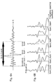
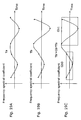
- Fig. 4 A is a diagram showing an audio signal in the time domain input to the time-frequency transforming unit 201.
- the signal in the part equivalent to the N-th frame is frequency-transformed at a time in the same diagram.
- Fig. 4 B is a diagram showing a frequency spectrum obtained by executing the time-frequency transform at a time to the audio signal in the N-th frame shown in Fig. 4 A. This diagram is plotted by using the frequency on a vertical axis and the frequency spectral coefficient value for the frequency on a horizontal axis.
- the signal in the time domain for the N-th frame is transformed to the signal in the frequency domain.
- the signal in the time domain and the signal in the frequency domain have the same number of effective samples.
- the number of the effective samples in the case of the MDCT, if the number of samples in the N-th frame shown in Fig. 4 A is 2048 samples, the number of independent frequency coefficients (MDCT coefficients) shown in Fig. 4 B is 1024 samples.
- the MDCT is an algorithm to overlap the frames by each half of the frames as shown in Fig. 3, the number of the samples newly input in Fig. 4 A is 1024 samples. Therefore, the numbers of the samples in Fig.
- Fig. 4 A and Fig. 4 B are considered to be the same in terms of each amount of data, so that the number of effective samples is regarded to be 1024 based on this.
- the number of the effective samples in the N-th frame may be 1024 as mentioned above, but it may be 128, or any discretional value. This value is predetermined between the encoding device 200 and a decoding device of the present invention.
- the audio input signal is also input to the time characteristic extracting unit 203 besides the time-frequency transforming unit 201.
- the time characteristic extracting unit 203 analyzes a temporal change of a given audio input signal, and decides whether the time resolution ability should be prioritized or the frequency resolution ability should be prioritized is decided when the audio input signal is quantized. That is to say, the time characteristic extracting unit 203 decides whether the audio input signal should be quantized in the frequency domain or in the time domain. It means, when the quantization takes place in the time domain, the temporal change of the audio input signal is informed to the decoding device by the signal in the time domain.
- the time characteristic extracting unit 203 decides to give the time resolution ability priority over the frequency resolution ability in the quantization in such band.
- a threshold value used by the time characteristic extracting unit 203 when deciding the change in the average energy is big (e.g.
- a threshold value for a difference in the average energy between adjacent sub-frames is defined according to an implementation method of the encoding device. Then, the time characteristic extracting unit 203 specifies a band for the audio input signal, for which the quantization should be done in the time domain. Selections of the band and the bandwidth are not limited to above.
- the method to specify the band at first, a signal containing a sample that gives a maximum amplitude (a peak signal) in the time domain is specified, and a frequency of the peak signal is calculated. Furthermore, the time characteristic extracting unit 203, for example, decides a bandwidth according to size of the peak signal, and specifies a band of the decided bandwidth, including the frequency obtained as a result of the calculation or a frequency close to it. In the time characteristic extracting unit 203, the decision result whether the time resolution ability is prioritized or the frequency resolution ability is prioritized, and the data indicating the specified band are output to the time-frequency transforming unit 201 and the encoded data stream generating unit 205.
- the frequency characteristic extracting unit 202 analyzes a characteristic of the frequency spectrum which is an output signal of the time-frequency transforming unit 201, and specifies a band which is better to be quantized in the time domain. For example, considering the encoding efficiency in the encoded data stream generating unit 205, there are many cases that the encoding efficiency is not improved in a band where the adjacent frequency spectral coefficients spread widely in the frequency spectrum, or a band where positive and negative codes of the adjacent frequency spectral coefficients are switched frequently or the like.
- the frequency characteristic extracting unit 202 samples a band applicable to these from the input frequency spectrum, outputs it to the time transforming unit 204, and also outputs a band inapplicable to these to the encoded data stream generating unit 205 as it is. Along with it, the data to specify the band output to the time transforming unit 204 is output to the encoded data stream generating unit 205.
- the encoded data stream generating unit 205 In the encoded data stream generating unit 205, the output signal of the frequency characteristic extracting unit 202 (data to specify a frequency spectrum and a band), the decision result of the time characteristic extracting unit 203 and the data to specify a band, and the output signal of the time transforming unit 204 (a frequency-time signal) are combined, and the encoded data stream is generated.
- Fig. 5 A is a diagram showing how an N-th frame is divided into a sub-frame 1 for its first half and a sub-frame 2 for its second half in the audio signal on the same time axis as one of Fig. 4 A.
- the diagram shows the case the sub-frame 1 and the sub-frame 2 have the same length, their lengths do not have to be the same or can overlap each other.
- the case the sub-frame 1 and the sub-frame 2 have the same length is used to simplify the explanation.
- Fig. 5 B is a diagram showing the frequency spectrum obtained by transforming the audio signal in the time domain of the sub-frame 1 shown in Fig. 5 A into a signal in the frequency domain.
- Fig. 5 C is a diagram showing the frequency spectrum obtained by transforming the audio signal in the time domain of the sub-frame 2 shown in Fig. 5 A into a signal in the frequency domain.
- the transform from the time domain to the frequency domain is conducted by using only the audio signal in each sub-frame, and the signal in the frequency domain (the frequency spectrum) obtained by the transform is supposed to be completely restored to the original signal in the time domain by executing its inverse transform (frequency-time transform).
- the MDCT transform mentioned previously is to transform a signal in the time domain in a frame having some temporal overlap each other into a signal in the frequency domain. However it causes a delay for reconstructing the signal in the time domain, so that it is not used for the case of deriving the frequency spectrum in Fig. 5 B and Fig. 5 C. Due to the same reason causing a delay, the polyphase filter or the like is not used.
- the number of samples respectively contained in the sub-frame 1 and the sub-frame 2 equals to a half of the sample quantity in the frame.
- the number of samples for the frequency spectrum in Fig. 5 A and Fig. 5 B respectively equals to a half of the sample quantity in the frame, so that these diagrams show a change in a ratio of frequency components in the same band as the band shown in Fig. 4 B at double intervals of the samples in a frequency axis direction. As shown in Fig.
- the frequency spectrum which shows a ratio of the frequency components contained in the entire audio input signal in the frame is obtained.
- the audio input signal in the frame is divided into the first half and the second half they are respectively transformed according to the time-frequency transform, it becomes clear that the ratio of the frequency components contained in each part of the audio signal is different between the first half and the second half in the N-th frame of the audio input signal. That is to say, the frequency spectrum shown in Fig. 5 B and Fig. 5 C indicates a temporal change in the ratio of the frequency components of the audio signal in the first half and the second half of the N-th frame.
- Fig. 5 B and Fig. 5 C show the example of the frequency spectrum for the case of dividing the N-th frame into two sub-frames and executing the time-frequency transform to each of the sub-frames.
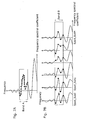
- the following describes a case that the N-th frame is further divided into (M+1) pieces of smaller sub-frames with reference to Fig. 6 A and Fig. 6 B.
- Fig. 6 A is a diagram showing how the audio signal (the N-th frame) in the time domain same as Fig. 4 A is divided into (M+1) pieces of sub-frames.
- Fig. 6 A is a diagram showing how the audio signal (the N-th frame) in the time domain same as Fig. 4 A is divided into (M+1) pieces of sub-frames.
- FIG. 6 B is a diagram showing the frequency spectrum obtained by dividing the audio input signal in a frame into (M+1) pieces of sub-frames and executing the time-frequency transform to each of the sub-frames.
- a signal SubP in the time domain of the sub-frame at a discretional location e.g. a P-th location (P is an integer)
- Spect_SubP a frequency spectral coefficient consisting of at least the same number of samples or more. The following supposes it is transformed to the frequency spectrum composing the same number of samples to simplify the explanation.
- Fig. 7 A is a diagram showing a sample contained in the frequency band BandA on the frequency spectrum obtained by executing the time-frequency transform at a time to the audio signal in the frame.
- the frequency spectrum of Fig. 7 A is the same as the frequency spectrum shown in Fig. 4 B. Also, Fig.
- FIG. 7 B is a diagram showing a sample contained in the frequency band BandB on the frequency spectrum obtained by dividing the audio input signal in the frame into (M+1) pieces of sub-frames and executing the time-frequency transform by each sub-frame. That is to say, the frequency spectrum in Fig. 7 B is the same as the frequency spectrum shown in Fig. 6 B.
- the frequency band BandA for the frequency spectrum in Fig. 7 A and the frequency band BandB for the frequency spectrum in Fig. 7 B indicate the same frequency band region. That is to say, the number of samples contained in the frequency band BandA equals to the number of samples contained in the frequency band BandB in the entire frame. It indicates that data of the frequency spectral coefficient (black diamonds in the diagram) in the frequency band BandA of Fig.
- the frequency spectral coefficient in the frequency BandB is quantized and encoded instead of quantizing and encoding the frequency spectral coefficient of the frequency band BandA. That is to say, the time transforming unit 204 executes, for example, a transform expression, which is equivalent to an inverse transform (frequency-time transform) of DCT transform, to the frequency band BandA where the time resolution ability is decided to be prioritized among the frequency spectra obtained by the time-frequency transforming unit 201, and outputs a frequency spectral coefficient equivalent to all of the samples (the frequency spectral coefficients)in the frequency band BandB indicated in Fig. 7 B.
- a transform expression which is equivalent to an inverse transform (frequency-time transform) of DCT transform
- Fig. 8 A is a diagram showing a sample in the frequency band BandC on the frequency spectrum obtained by executing the time-frequency transform to the audio signal in a frame.
- FIG. 8 B is a diagram showing a sample in the frequency band BandD on the frequency spectrum obtained by dividing the audio input signal in a frame into (M+1) pieces of sub-frames and executing the time-frequency transform by each sub-frame.
- the frequency spectrum in Fig. 8 A is the same as the frequency spectrum shown in Fig. 4 B
- the frequency spectrum in Fig. 8 B is the same as the frequency spectrum shown in Fig. 6 B.
- the frequency band BandC in the frequency spectrum in Fig. 8 A and the frequency band BandD in the frequency spectrum in Fig. 8 B show the same frequency band.
- Fig. 8 A shows the same frequency band.
- the frequency band BandD when the frequency band BandD is selected to have a piece of the sample (the frequency spectral coefficient)that belongs to the frequency band BandD in each of (M+1) pieces of the sub-bands, the number of samples in the frequency band BandC, which is the same frequency band in the frequency spectrum shown in Fig. 8 A is (M+1) pieces. Because each sample that belongs to the frequency band BandD shown in Fig. 8 B is selected from each of (M+1) pieces of the sub-frames, if each sample is plotted by using the time on a horizontal axis and the frequency spectral coefficient on a vertical axis, it is possible to say that it indicates a temporal change in a frequency spectral coefficient that belongs the frequency band BandC in a frame of the audio signal.
- Fig. 9 A is a diagram showing a sample in the frequency band BandC on the frequency spectrum obtained by executing the time-frequency transform at a time to the audio signal in a frame.
- Fig. 9 B is a diagram that each sample (a frequency spectral coefficient) shown in Fig. 8 B is re-plotted by using the time on the horizontal axis and the frequency spectral coefficient value on the vertical axis.
- the signal which is made up of extracting one sample from each of (M+1) pieces of sub-frames in the same frequency band BandD, re-plotted as shown in Fig.
- each sample (the frequency spectral coefficient) in the frequency band BandC shown in Fig. 9 A can be treated as data almost same as the time frequency signal (the frequency band BandD) in Fig. 9 B. Therefore, in the explanation hereinafter, to quantize the frequency spectral coefficient in Fig. 9 A is indicated as "perform Qf", and to quantize the time -frequency signal in Fig. 9 B is indicated as "perform Qt".
- a part of the frequency spectral coefficient of the frequency spectrum obtained by the time-frequency transforming unit 201 i.e. the frequency spectral coefficient stream contained in the frequency band BandC in Fig. 9 A is transformed to the time-frequency signal in the time domain in Fig. 9 B. Going through this transform is equivalent to the transform from the frequency spectral coefficient stream contained in the frequency band BandC in Fig. 8 A to the frequency spectral coefficient stream contained in the frequency band BandD in Fig. 8 B, which is explained before. Or, it is equivalent to the transform from the frequency spectral coefficient stream in the frequency band BandA in Fig. 7 A to the frequency spectral coefficient stream in the frequency band BandB in Fig. 7 B.
- the encoded data stream generating unit 205 shown in Fig. 2 quantizes and encodes the output from the time-frequency transforming unit 201 and the output from the time transforming unit 204, which is transformed as above, and outputs the encoded data stream.
- publicly known techniques such as the Huffman coding and the vector quantization are used.
- the encoded data stream generating unit 205 may divide several pieces of samples of the time-frequency signal located in a part which has less fluctuation of amplitude into groups, and then quantize and encode its average gain for each of the groups.
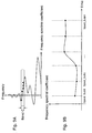
- Fig. 10 is a diagram showing encoding of the time-frequency signal by the encoded data stream generating unit 205 shown in Fig. 2. As shown in Fig.
- the encoded data stream generating unit 205 finds an average gain Gt1 and an average gain Gt2 respectively for a sample group from a frequency spectral coefficient Spec_Sub 0 to a frequency spectral coefficient Spec_Sub 2 and a sample group from a frequency spectral coefficient Spec_Sub 3 to a frequency spectral coefficient Spec_Sub M, and quantizes and encodes data specifying each of the sample groups and the average gain in each of the groups in stead of quantizing and encoding the time-frequency signal itself from the frequency spectral coefficient Spec_Sub 0 to the frequency spectral coefficient Spec_Sub M.
- the time-frequency signal shown in Fig. 10 can be expressed as two data groups, (0, 2, Gt1) and (3, M, Gt2). Also, in this case, it is not necessary to group all of each sample for the time-frequency signal. It may group samples only in a part having less fluctuation of the amplitude. For the part having a radical fluctuation of the amplitude, the frequency spectral coefficient value itself in each sample may be quantized and encoded.
- Fig. 11 is a diagram showing how an output signal of the time-frequency transforming unit 201 is corresponded to the data indicating the band time-transformed by the time transforming unit 204.
- the vertical axis shows the frequency
- the horizontal axis shows the frequency spectral coefficient corresponding to the frequency on the vertical axis.
- the frequency spectral coefficient indicates the MDCT coefficient in the same diagram.
- a part shown in a dotted line is the part that is not quantized and encoded by the encoded data stream generating unit 205.
- the time-frequency signal corresponding to this band is quantized and encoded.
- the same diagram describes an example for a case that a frequency axis direction is divided into 5 bands, and the quantization is carried out in an order of Qf, Qt, Qf, Qt and Qf from its low frequency.
- the encoded data stream output from the encoded data stream generating unit 205 includes at least data indicating whether each of the bands is quantized and encoded in the time domain or in the frequency domain, and data quantized and encoded in each of the bands.
- the number of band divisions and the quantization method for each band (i.e. whether Qf or Qt) in the encoding device 200 are not fixed, and they are not limited to this example.
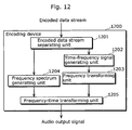
- Fig. 12 is a block diagram showing the structure of a decoding device 1200 according to the first embodiment of the present invention.
- This decoding device 1200 is a decoding device that decodes the encoded data stream output by the encoding device 200, and outputs an audio signal having an advanced level of the time resolution ability, which includes an encoded data stream separating unit 1201, a time-frequency signal generating unit 1202, a frequency transforming unit 1203, a frequency spectrum generating unit 1204 and a frequency-time transforming unit 1205.
- the encoded data stream separating unit 1201 separates encoded data in a band indicated as "Qf” and encoded data in a band indicated as “Qt” from an encoded data stream as an input signal, outputs the encoded data in the band indicated as “Qf” to the frequency spectrum generating unit 1204, and outputs the encoded data in the band indicated as "Qt” to the time-frequency signal generating unit 1202.
- the encoded data in the band indicated as "Qf” is data quantized and encoded in the frequency domain in the encoding device 200.
- the encoded data in the band indicated as "Qt” is data quantized and encoded in the time domain in the encoding device 200.
- the frequency spectrum generating unit 1204 decodes the input encoded data, further inverse-quantizes it, and generates a frequency spectrum on the frequency axis.
- the time-frequency signal generating unit 1202 decodes the input encoded data, inverse-quantizes it, and temporally generates a time-frequency signal on the time axis.
- the temporally generated time-frequency signal is input to the frequency transforming unit 1203.
- the frequency transforming unit 1203 transforms the input time-frequency signal from the frequency spectral coefficient in the time domain to the frequency spectral coefficient in the frequency domain based on a unit of a number of samples less than the ones in a frame by using a transform expression equivalent to inverse transform of the transform expression used by the time transforming unit 204 of the encoding device 200.
- Data which indicates a temporal change expressed in the time-frequency signal, is reflected on the frequency spectral coefficient obtained as a result of the partial transform to the frame according to above, and this frequency spectral coefficient is output to the frequency-time transforming unit 1205.
- the frequency-time transforming unit 1205 the frequency spectrum in the frequency domain, which is an output signal from the frequency spectrum generating unit 1204 and the frequency transforming unit 1203, is composed on the frequency axis, and transformed to an audio signal on the time axis. In this way, a time component expressed by the time-frequency signal can be reflected on the frequency spectrum output from the frequency spectrum generating unit 1204, and an audio signal having high time resolution ability can be obtained.
- a transform method which is an inverse process of the time-frequency transforming unit 201 conducted in the encoding device 200, is used.
- the MDCT transform is used in the time-frequency transforming unit 201 in the encoding device 200
- inverse MDCT transform is used in the frequency-time transforming unit 1205.
- the output of the frequency-time transforming unit 1205 obtained in this way is, for example an audio output signal expressed by a discrete temporal change in a voltage.
- this method provides possibility of more flexible and more efficient data encoding rather than the encoding method only in the frequency domain or the encoding method only in the time domain. As a result of it, it enables to encode a lot of data in a given amount of data and achieve a high quality of the audio signal reproduced.
- the time characteristic extracting unit 203 decides the time resolution ability should be prioritized when a change in the average energy between sub-frames (i.e. a difference between adjacent sub-frames) is bigger than the predefined threshold value
- a decision criterion for the time characteristic extracting unit 203 to decide whether the time resolution ability is prioritized or the frequency resolution ability is prioritized is not limited to the above method.
- the frequency characteristic extracting unit 202 decides the quantization in the time domain should be carried out to the band where the adjoined frequency spectral coefficients spread widely in the frequency spectrum, or the band where negative and positive codes are frequently switched, a decision criterion for this decision is not limited to the above method, either.
- Methods of the quantization and the encoding in the second embodiment are different from the ones in the first embodiment.
- the first embodiment for the audio input signal transformed into the frequency domain by each frame, the one in a certain band in the frame is quantized as it is, but the one in another band is re-transformed into the time domain and then the signal in the time domain is quantized.
- quantization and encoding are performed by the signal in other band.
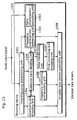
- Fig. 13 is a block diagram showing the structure of an encoding device 1300 according to the second embodiment of the present invention.
- the encoding device 1300 includes a time-frequency transforming unit 1301, a frequency characteristic extracting unit 1302, a time characteristic extracting unit 1303, a quantizing and encoding unit 1304, a reference band deciding unit 1305, a time transforming unit 1306, a time composing and encoding unit 1307, a frequency composing and encoding unit 1308 and an encoded data stream generating unit 1309.
- the time-frequency transforming unit 1301, the frequency characteristic extracting unit 1302, the time characteristic extracting unit 1303 and the time transforming unit 1306 are almost identical to the time-frequency transforming unit 201, the frequency characteristic extracting unit 202, the time characteristic extracting unit 203 and the time transforming unit 204 respectively in the encoding device 200 shown in Fig. 2.
- the audio input signal is input to the time-frequency transforming unit 1301 and the time characteristic extracting unit 1303 by each frame of a certain time length.
- the time-frequency transforming unit 1301 transforms the input signal in the time domain into a signal in the frequency domain.
- the time-frequency transforming unit 1301, for example obtains an MDCT coefficient using the MDCT transform.
- the frequency characteristic extracting unit 1302 analyzes a frequency characteristic of the frequency spectral coefficient transformed by each frame, which is the output of the time-frequency transforming unit 201, and specifies a band that is better to be quantized with giving the time resolution ability priority in the same way as the frequency characteristic extracting unit 202 in Fig. 2.
- the time characteristic extracting unit 1303 decides whether the time resolution ability should be prioritized or the frequency resolution ability should be prioritized to quantize the audio signal input per each frame. In the time characteristic extracting unit 1303, because it is not necessary to quantize and encode all of the bands for the input signal with the same time resolution ability or the same frequency resolution ability, the decision can be made by each sub-frame or by each frequency band.
- the quantizing and encoding unit 1304 quantizes and encodes signal by each predefined band.
- This quantizing and encoding unit 1304 quantizes and encodes data using publicly known techniques that are familiar to the people concerned such as the vector quantization and the Huffman coding.
- the quantizing and encoding unit 1304 internally contains a memory not shown in a diagram, holds an encoded data stream that has been encoded already and a frequency spectrum before encoding in its memory, and outputs the encoded data stream or the frequency spectrum before encoding in the band decided by the reference band deciding unit 1305 to the reference band deciding unit 1305.
- the reference band deciding unit 1305 decides a band that should be referred for the band specified by the frequency characteristic extracting unit 1302 and the time characteristic extracting unit 1303 in the encoded data stream as the output of the quantizing and encoding unit 1304.
- the reference band deciding unit 1305 quantizes and encodes only the first specified band, without referring to other band, in the time domain and encodes the rest of the bands in the time domain with reference to the frequency spectrum in the band.
- the reference band deciding unit 1305 quantizes and encodes, in the frequency domain, for example, only the band containing a component (the frequency spectral coefficient) in the lowest frequency among the bands including the frequency spectral coefficient. For example, if the frequency components of 8kHz, 16kHz and 24kHz are contained respectively in the bands specified by the frequency characteristic extracting unit 1302, only the band containing the frequency component of 8kHz is quantized and encoded. Regarding any bands other than that, e.g.
- the band containing the frequency component of 16kHz and the band containing the frequency component of 24kHz are decided to be encoded in the frequency domain with reference to the band containing the component (the frequency spectral coefficient) of the lowest frequency (8kHz) as a referred band. If the frequency spectral coefficient equivalent to harmonic overtone among the bands specified by the frequency characteristic extracting unit 1302 is not contained, the frequency characteristic extracting unit 1302 decides to quantize and encode these bands in the time domain without reference to other band.
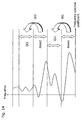
- Fig. 14 is a diagram showing an example of a method for generating an encoded data stream of a target band with reference to other band.
- the vertical axis shows a frequency and the horizontal axis shows a frequency spectral coefficient value for the frequency on the diagram.
- both of a frequency band Base1 and a frequency band Base2 are a part of a band of which coefficient of its frequency domain signal (a frequency spectrum) has already been quantized and encoded by the quantizing and encoding unit 1304.
- the signal in the bands indicated as “Qt1” and “Qt2” are meant to be the ones quantized and encoded by using the frequency spectral coefficients of the frequency band Base1 and of the frequency band Base2 respectively.
- “Qt1” means to be quantized and encoded according to the time domain transform using the signal of the frequency band Base1
- the band “Qf2” means to be quantized and encoded in the frequency domain using the signal of the Base2.
- a parameter for expressing "Qt1" with use of the band signal of Base1 is defined as a parameter Gt1
- a parameter for expressing "Qf2" with use of the band signal of the frequency band Base2 is defined as a parameter Gf2.
- the signal in the band "Qt1" is quantized and encoded by the signal in the band of the frequency band Base1 expressed in the time domain with the parameter indicated as the parameter Gt1
- the signal in the band "Qf2” is quantized and encoded by the signal in the band of Base2 expressed in the frequency domain (but the transform is not needed because it is already expressed in the frequency domain), with the parameter indicated as the parameter Gf2.
- a method for dividing the band, its sequence and quantity are not limited to these.
- Fig. 15 is a diagram showing another example of the method for generating the encoded data stream of the target band with reference to other band.
- a signal of "Qt" may be expressed by a sum of addition by using both of two bands (expressed in the time domain) of the frequency band Base1 and the frequency band Base2 that have already been quantized and encoded in the quantizing and encoding unit 1304, with the parameter Gt1 and the parameter Gt2 respectively.
- Fig. 16 is a diagram showing other examples of the method for generating the encoded data stream of the target band with reference to other band. Just as the case of Fig.
- a signal of "Qf" may be expressed by a sum of addition by using both of two bands (expressed in the frequency domain) of the frequency band Base1 and the frequency band Base2 that have already been quantized and encoded in the quantizing and encoding unit 1304 with the parameter Gf1 and the parameter Gf2 respectively.
- Either of the cases in Fig. 15 and Fig. 16 illustrates the case a certain frequency band is quantized and encoded by using the signal in two bands that have already been quantized and encoded, but the number of bands is not limited to two.
- a band subject for quantization and encoding (the target band) specified by the time characteristic extracting unit 203 among the frequency spectral coefficients in a frame is expressed by using either of the bands (the referred band) that are quantized and encoded by the quantizing and encoding unit 1304, and whether quantization and encoding are carried out to it or not is decided.
- Fig. 17 is a diagram showing an example of a method for which a frequency spectrum in a target domain is composed in the frequency domain by using the encoded data stream in the referred band that has already been quantized and encoded.
- a band A is the referred band
- a band B is the target band.
- the signal in the band A and the signal in the band B respectively consist of the same number of elements, and each is respectively described as a vector Fa and a vector Fb. Additionally, each vector is divided into two, i.e.
- the number of elements of Fa0 is the same as the number of elements of Fb0
- the number of elements of Fa1 is the same as the number of elements of Fb1.
- the number of elements of Fa0 may or may not be the same as the number of elements of Fa1.
- a parameter Gb (Gb0, Gb1) is defined.
- the parameter Gb is a vector, but Gb0 and Gb1 are a scalar value.
- a vector Fb', which is an approximation of the vector Fb is defined as the following formula by using the vector Fa and the parameter Gb. [ Formula 1 ]
- the signal in the frequency domain for the target band B is composed by getting a product from the signal in the frequency domain for the target band A multiplied by the parameter Gb that controls a composing ratio.
- the frequency composing and encoding unit 1308 quantizes and encodes data showing which referred band expresses a specific target band and the parameter Gb used for a gain control over the referred band.
- the target band and the referred band are divided into two vectors has been described. But they may be divided into less or more than two. And, dividing a band may or may not be even.
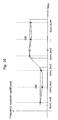
- Fig. 18 is a diagram show an example of a method for which the frequency spectrum for the target domain is composed in the time domain by using the encoded data stream in the referred band that has already been quantized and encoded.
- a signal in the referred band and a signal in the target band have been selected by the reference band deciding unit 1305.
- a band A is the referred band
- a band B is the target band.
- the signal in the band A and the signal in the band B consist of the same number of elements respectively.
- the time transforming unit 1306 transforms the signals in the frequency domain in the band A and in the band B into signals in the time domain (Tt) in the same way as the time transforming unit 204 of the first embodiment.
- the signals obtained by transforming the signals in the frequency domain of the band A and the band B are respectively a vector Ta and a vector Tb.
- Ta0, Ta1, Tb0 and Tb1 are a vector.
- the number of elements of Ta0 are the same as the number of elements of Tb0, and the number of element of Ta1 is the same as the number of elements of Tb1.
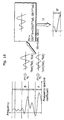
- Fig. 19 A, Fig. 19 B and Fig. 19 C are diagrams showing an example of a method that approximates the vector Tb as the signal in the time domain of the band B by using the vector Ta as the signal in the time domain of the band A.
- Fig. 19 A is a diagram showing the vector Ta expressing the signal obtained by transforming the signal in the frequency domain of the band A as the referred band into the one in the time domain.
- FIG. 19 B is a diagram showing the vector Tb expressing the signal obtained by transforming the signal in the frequency domain of the band B as the target band into the one in the time domain.
- Fig. 19 C is a diagram showing an approximate vector Tb' for the case expressing a vector approximated to the vector Tb by performing a gain control over the vector Ta.
- a value of the parameter Gb is decided to have the vector Ta multiplied by Gb approximate to the vector Tb.
- Tb' is defined as the following formula by using the vector Ta and the parameter Gb.
- the signal in the time domain for the target band B is composed by the signal in the time domain for the referred band A with the parameter Gb that performs the gain control. Therefore, in the time composing and encoding unit 1307, the data that shows which referred band is used to express a certain target band and the parameter Gb used for the gain control over the referred band are quantized and encoded.
- the case for dividing the target band and the referred band into two vectors has been described, but they may be divided less or more than two. Also, dividing a band may or may not be even.
- the encoded data stream which is an output signal of the encoding device 1300, contains following data: 1. Data obtained by quantizing and encoding signals in a referred band and in a band that is not a referred nor a target band; 2. Data indicating a relation between the referred band and the target band; 3. Data indicating how the target band is quantized and encoded by using the signal in the referred band; 4.
- Data indicating in which of the domains, the time domain or the frequency domain, the referred band, the target band and a band categorized as neither of them are quantized and encoded; and so forth. Also, the numbers of samples in the referred band and in the target band and the frequency relevant to each of the bands are contained directly or indirectly in the encoded data stream.
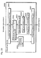
- Fig. 20 is a block diagram showing the structure of the decoding device 2000 according to the second embodiment.
- This decoding device 2000 is a decoding device that decodes an encoded data stream generated by the encoding device 1300 and outputs an audio output signal, which includes an encoded data stream separating unit 2001, a reference frequency signal generating unit 2002, a time transforming unit 2003, a time composing unit 2004, a frequency transforming unit 2005, a frequency composing unit 2006, and a frequency-time transforming unit 2007.
- the frequency-time transforming unit 2007, the time transforming unit 2003 and the frequency transforming unit 2005 in the decoding device 2000 respectively have the same structure as the frequency-time transforming unit 1205, the time transforming unit 1306 and the frequency transforming unit 1203 in the first embodiment.
- the encoded data stream separating unit 2001 reads a header and the like in the input encoded data stream, separates following data contained in the encoded data stream: 1. Data obtained by quantizing and encoding a signal in a referred band and in a band that is not a referred nor target band; 2. Data indicating a relation between the referred band and the target band; 3. Data indicating how the target band is quantized and encoded by using the signal of the referred band; 4.
- the reference frequency signal generating unit 2002 uses a publicly known decoding method, which is familiar to the people concerned, such as Huffman decoding, and encodes the signal in the frequency domain. It means that signals of Base1 and Base2 in Fig. 14 to Fig. 16 are decoded. Also, it means the signals in the frequency domain of the band A in Fig. 17 and Fig. 18 are decoded.
- the signal (the frequency spectrum) in the frequency domain expressed as the vector Fa in the band A is obtained by decoding and inverse-quantizing the data in the referred band, which is input to the reference frequency signal generating unit 2002 from the encoded data stream separating unit 2001, in the reference frequency signal generating unit 2002.
- the signal (the frequency spectrum) in the frequency domain expressed as the vector Fb in the band B is approximated by the approximate vector Fb' composed by using the vector Fa and the parameter Gb according to the formula 1.
- the parameter Gb for the gain control is obtained by separating from the encoded data stream in the encoded data stream separating unit 2001, and the data indicating that the band A is the referred band of the band B is also obtained by separating from the encoded data stream in the encoded data stream separating unit 2001.
- the signal Fb in the frequency domain of the band B as the referred band is generated by generating the approximate vector Fb'.
- the signal (the time-frequency signal) in the time domain of the band A indicated as the vector Ta is obtained by executing the time transform (the process of Tf in Fig. 18) through the time transforming unit 2003 to the frequency spectrum indicated as the vector Fa obtained by the reference frequency signal generating unit 2002.
- the signal (the time-frequency signal) in the time domain indicated as the vector Tb in the band B as a target band is approximated by the approximate vector Tb'.
- This approximate vector Tb' is composed by the vector Ta and the parameter Gb according to the formula 2.
- the signal Tb in the time domain of the band B as a target band is generated by generating the approximate vector Tb'.
- the parameter Gb for the gain control and the data indicating that the band A is the referred band of the band B are obtained from the encoded data stream separating unit 2001.
- the signal in the time domain indicated as the approximate vector Tb' obtained by the time composing unit 2004 is transformed to a signal in the frequency domain by the frequency transforming unit 2005.
- outputs of the reference frequency signal generating unit 2002, of the frequency composing unit 2006 and of the frequency transforming unit 2005 are composed as a signal component on a frequency axis.
- the frequency-time transforming unit 2007 executes an inverse transform of the time-frequency transform to the composed frequency spectrum by the time-frequency transforming unit 1301 of the encoding device 1300, and obtains the audio output signal in the time domain.
- the frequency-time transform e.g. inverse MDCT transform
- the frequency-time transform in the frequency-time transforming unit 2007 can be carried out easily by publicly known techniques, which is familiar to the people concerned.
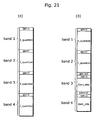
- Fig. 21 A is a diagram showing an example of the data structure of the encoded data stream generated by the encoded data stream generating unit 205 in Fig. 2.
- Fig. 21 B is a diagram showing an example of the data structure of the encoded data stream generated by the encoded data stream generating unit 1309 in Fig. 13.
- a bandwidth of each band indicated in Fig. 21 A and Fig. 21 B may or may not be a fixed bandwidth.
- the frequency spectrum in the band specified by the frequency characteristic extracting unit 202 and the time characteristic extracting unit 203 is quantized and encoded after it is further transformed to a time-frequency signal by the time transforming unit 204. Any bands other than that are quantized and encoded as they are the frequency spectrum.
- Fig. 21 A shows the case that bands specified by the frequency characteristic extracting unit 202 and the time characteristic extracting unit 203 are a band 1 and a band 4.
- a header is described in the front of each band.
- a flag is described in each header, which shows in which of the domains, the time domain or the frequency domain, the encoded data stream in the band is quantized and encoded.
- the encoded data streams f_quantize and the encoded data streams t_quantize are an encoded data stream obtained by quantizing and encoding the frequency spectrum in the frequency domain and the time domain respectively.
- the frequency spectrum in the bands specified by the frequency characteristic extracting unit 1302 and the time characteristic extracting unit 1303 is encoded by the following four types of the encoding method:
- a flag whether the band refers to other band or not, a band number to show which band is referred if refers to, a parameter to control the gain of the referred band, and so on are described in the header for each band in the encoded data stream.
- a parameter Gain_info which controls the gain of the referred band band 1; and so on.
- a parameter Gain_info to control the gain of the referred band band 2 and the like are described.
- a flag showing in which of the domains, the time domain or the frequency domain, the encoded data stream in the band is quantized and encoded is described in the header of each band in the encoded data stream. But if which band is quantized and encoded in which domain is predetermined, this flag is not necessary.
- a flag showing whether the band refers to other band or not, and a band number specifying a referred band for the band are described in the header of each band in each encoded data stream. But if which band refers to which band is predetermined, these data is not necessary.
- the referred band is selected to a band with lower frequency components and the target band is selected to a band with higher frequency components than the referred band
- the referred band is encoded by an existing encoding method, and a code to generate components in the target band is encoded as supplemental data, it is further possible to reproduce sound in a broad band by using the existing encoding method and a small volume of the supplemental data.
- the AAC method When the AAC method is used as an existing audio encoding method, it is possible to decode the encoded data stream without making a noise even in a decoding method compatible to the AAC method as long as encoding data to generate components in the target band is included in Fill_element of the AAC method. It is also possible to reproduce sound in a wider band from a relatively small amount of data when the decoding method according to the second embodiment of the present invention is used.
- the encoding device and the decoding device in the present invention structured as above are used, data encoding in the time domain can be carried out in addition to the data encoding in the frequency domain. Therefore, by selecting an encoding method with a higher encoding efficiency, the frequency resolution ability and the time resolution ability can be efficiently improved for the decoded sound that is reproduced. Also, because it is possible to construct the encoded audio data stream with a small volume of data by reusing the signal in the band which has already been encoded, a bit rate for the encoded audio data stream can be kept in a low level. Additionally, if the same bit rate is used, an encoded audio data stream that can obtain an audio signal having a high level of sound quality can be provided.
- any additional arithmetic delay in the encoding device and the decoding device can be removed, so that it has a merit in an application where consideration of the delay is required in the encoding and decoding processes.
- the reference band deciding unit 1305 decides four types of the encoding method for the band specified by the frequency characteristic extracting unit 1302 and the time characteristic extracting unit 1303, but its actual decision method is not limited to the above.
- the encoding device is useful as an audio encoding device which is located in a broadcast station for a satellite broadcasting including BS and CS, as an audio encoding device for a content distribution server which distributes contents via a communication network such as the Internet, and further as a program for encoding audio signals which is executed by a general-purpose computer.
- the decoding device is useful not only as an audio decoding device which is located in an STB at home, but also as a program for decoding audio signals which is executed by a general-purpose computer, a PDA, a cellar phone and the like, and a circuit board, an LSI or the like only for decoding audio signals which is included in an STB or a general-purpose computer, and further as an IC card which is inserted into an STB or a general-purpose computer.
Landscapes
- Engineering & Computer Science (AREA)
- Physics & Mathematics (AREA)
- Spectroscopy & Molecular Physics (AREA)
- Computational Linguistics (AREA)
- Signal Processing (AREA)
- Health & Medical Sciences (AREA)
- Audiology, Speech & Language Pathology (AREA)
- Human Computer Interaction (AREA)
- Acoustics & Sound (AREA)
- Multimedia (AREA)
- Compression, Expansion, Code Conversion, And Decoders (AREA)
Claims (26)
- Dispositif de codage qui code un signal dans un domaine des fréquences obtenu en transformant un signal d'origine d'entrée conformément à une transformation temps-fréquence et génère un signal de sortie comprenant :une première unité de spécification de bande pouvant être mise en oeuvre pour spécifier une bande pour une partie d'un spectre de fréquences sur la base d'une caractéristique du signal d'origine d'entrée,une unité de transformation en temps pouvant être mise en oeuvre pour transformer un signal dans la bande spécifiée en un signal conformément à une transformation fréquence-temps, etune unité de codage pouvant être mise en oeuvre pour coder le signal obtenu par l'unité de transformation en temps et au moins une partie du spectre de fréquences, et générer un signal de sortie à partir du signal codé et du spectre de fréquences codé.
- Dispositif de codage selon la revendication 1,
dans lequel l'unité de transformation en temps transforme le signal dans la bande spécifiée en un signal indiquant une variation dans le temps d'une composante de fréquence à un temps identique à celui du spectre de fréquences conformément à la transformation fréquence-temps. - Dispositif de codage selon la revendication 2,
dans lequel le dispositif de codage comprend en outre une unité d'approximation dans le domaine du temps pouvant être mise en oeuvre pour spécifier deux ou plusieurs bandes du spectre de fréquences, et réaliser une approximation, en utilisant un signal indiquant une variation dans le temps d'une composante de fréquence contenue dans l'une des bandes spécifiées, d'un signal indiquant une variation dans le temps d'une composante de fréquence dans une autre bande spécifiée, et
l'unité de codage code le signal utilisé pour l'approximation de la bande spécifiée par l'unité d'approximation dans le domaine du temps. - Dispositif de codage selon la revendication 3,
dans lequel l'unité d'approximation dans le domaine du temps génère des données qui spécifie la bande utilisée pour l'approximation et la bande approchée dans le spectre de fréquences. - Dispositif de codage selon la revendication 4,
dans lequel l'unité d'approximation dans le domaine du temps génère en outre des données qui indiquent un gain du signal utilisé pour l'approximation du signal approché. - Dispositif de codage selon la revendication 5,
dans lequel l'unité de codage code, à la place du signal approché, les données qui spécifient la bande utilisée pour l'approximation et les données qui indiquent le gain, qui sont générées par l'unité d'approximation dans le domaine du temps. - Dispositif de codage selon la revendication 1,
dans lequel la première unité de spécification de bande spécifie une bande de fréquences pour une partie ayant une variation importante d'énergie moyenne du signal d'origine d'entrée. - Dispositif de codage selon la revendication 1,
dans lequel le dispositif de codage comprend en outre une seconde unité de spécification de bande pouvant être mise en oeuvre pour spécifier une bande pour une partie du spectre de fréquences sur la base d'une caractéristique du spectre de fréquences, et
l'unité de transformation en temps transforme un signal de la bande spécifiée en un signal conformément à la transformation fréquence-temps. - Dispositif de codage selon la revendication 8,
dans lequel le dispositif de codage comprend en outre une unité d'approximation dans le domaine des fréquences pouvant être mise en oeuvre pour spécifier deux ou plusieurs bandes contenues dans le spectre de fréquences, et réalise une approximation, en utilisant un spectre de fréquences d'une des bandes spécifiées, d'un spectre de fréquences d'une autre bande, et
l'unité de codage code le spectre de fréquences utilisé pour l'approximation de la bande spécifiée par l'unité d'approximation dans le domaine des fréquences. - Dispositif de codage selon la revendication 9,
dans lequel l'unité d'approximation dans le domaine des fréquences génère des données qui spécifient la bande utilisée pour l'approximation et la bande approchée dans le spectre des fréquences. - Dispositif de codage selon la revendication 10,
dans lequel l'unité d'approximation dans le domaine des fréquences génère en outre des données qui indiquent un gain du spectre de fréquences utilisé pour l'approximation du spectre de fréquences approché. - Dispositif de codage selon la revendication 11,
dans lequel l'unité de codage code, à la place du spectre de fréquences approché, les données qui spécifient la bande utilisée pour l'approximation et les données qui indiquent le gain, qui sont générées par l'unité d'approximation dans le domaine des fréquences. - Dispositif de codage selon la revendication 8,
dans lequel la seconde unité de spécification de bande spécifie une bande ayant un large étalement des coefficients spectraux de fréquences dans le spectre de fréquences. - Dispositif de décodage qui décode un flux de données codées obtenu en codant un signal d'origine d'entrée, et fournit en sortie un spectre de fréquences, comprenant :une unité de décodage pouvant être mise en oeuvre pour extraire une partie du flux de données codées contenu dans le flux de données codées d'entrée, et décoder le flux de données codées extrait,une unité de transformation en fréquence pouvant être mise en oeuvre pour transformer un signal obtenu en décodant le flux de données codées extrait en un spectre de fréquences, etune unité de composition pouvant être mise en oeuvre pour composer un spectre de fréquences, qui est obtenu en décodant un flux de données codées extrait à partir d'une autre partie du flux de données codées d'entrée, et le spectre de fréquences qui est obtenu par l'unité de transformation en fréquence sur un axe des fréquences.
- Dispositif de décodage selon la revendication 14,
dans lequel le spectre de fréquences obtenu par l'unité de transformation en fréquence et le spectre de fréquences obtenu en décodant le flux de données codées extrait d'une autre partie du flux de données codées, constituent un spectre de fréquences qui indique un signal à un temps identique à celui du même signal d'origine d'entrée. - Dispositif de décodage selon la revendication 15,
dans lequel le dispositif de décodage comprend en outre une unité d'approximation en temps pouvant être mise en oeuvre pour réaliser une approximation d'une bande, qui est indiquée par le flux de données codées extrait, par un signal décodé à partir d'un flux de données codées dans une autre bande, et
l'unité de transformation en fréquence transforme le signal approché en un spectre de fréquences. - Dispositif de décodage selon la revendication 16,
dans lequel l'unité d'approximation en temps spécifie une bande du signal, qui est utilisée pour l'approximation de la bande indiquée par le flux de données codées, conformément aux données contenues dans le flux de données codées extrait, et exécute l'approximation en utilisant le signal de la bande spécifiée. - Dispositif de décodage selon la revendication 17,
dans lequel l'unité d'approximation en temps réalise en outre une approximation de la bande en mesurant un gain du signal utilisé pour l'approximation du signal approché à partir des données contenues dans le flux de données codées extrait, et en ajustant une amplitude du signal dans la bande spécifiée en utilisant le gain mesuré. - Dispositif de décodage selon la revendication 17,
dans lequel l'unité d'approximation en temps spécifie une bande déjà transformée en un spectre de fréquences, transforme le spectre de fréquences de la bande spécifiée en un signal conformément à la transformation fréquence-temps et réalise une approximation d'une bande indiquée par le flux de données codées extrait en utilisant le signal obtenu par la transformation. - Dispositif de décodage selon la revendication 16,
dans lequel le dispositif de décodage comprend en outre une unité d'approximation en fréquence pouvant être mise en oeuvre pour réaliser une approximation de la bande, qui est indiquée par le flux de données codées extrait, par un spectre de fréquences décodé à partir d'un flux de données codées dans une autre bande, et l'unité de composition compose en outre le spectre de fréquences approché par l'unité d'approximation en fréquence sur l'axe des fréquences, en plus du spectre de fréquences obtenu en décodant le flux de données codées extrait d'une autre partie du flux de données codées d'entrée, et le spectre de fréquences obtenu par l'unité de transformation en fréquence. - Dispositif de décodage selon la revendication 20,
dans lequel l'unité d'approximation en fréquence spécifie une bande du spectre de fréquences utilisé pour l'approximation de la bande indiquée par le flux de données codées, conformément aux données contenues dans le flux de données codées extrait, et exécute l'approximation en utilisant le spectre de fréquences de la bande spécifiée. - Dispositif de décodage selon la revendication 21,
dans lequel l'unité d'approximation en fréquence réalise en outre une approximation de la bande en mesurant un gain du spectre de fréquences utilisé pour l'approximation du spectre de fréquences approché à partir des données contenues dans le flux de données codées extrait, et en ajustant une amplitude du spectre de fréquences dans la bande spécifiée en utilisant le gain mesuré. - Procédé de codage destiné à coder un signal dans le domaine des fréquences obtenu en transformant un signal d'origine d'entrée conformément à une transformation temps-fréquence, et générer un signal de sortie, comprenant :une première étape de spécification de bande destinée à spécifier une bande pour une partie d'un spectre de fréquences sur la base d'une caractéristique du signal d'origine d'entrée,une étape de transformation en temps destinée à transformer un signal de la bande spécifiée en un signal conformément à une transformation fréquence-temps, etune étape de codage destinée à coder le signal obtenu par l'étape de transformation en temps et au moins une partie du spectre de fréquences, et générer un signal de sortie à partir du signal codé et du spectre de fréquences codé.
- Procédé de décodage destiné à décoder un flux de données codées obtenu en codant un signal d'origine d'entrée, et fournir en sortie un spectre de fréquences, comprenant :une étape de décodage destinée à extraire une partie du flux de données codées contenu dans le flux, de données codées d'entrée, et décoder le flux de données codées extrait,une étape de transformation en fréquence destinée à transformer un signal obtenu en décodant le flux de données codées extrait en un spectre de fréquences, etune étape de composition destinée à composer un spectre de fréquences, qui est obtenu en décodant un flux de données codées extrait à partir d'une autre partie du flux de données codées d'entrée, et le spectre de fréquences, qui est obtenu par l'étape de transformation en fréquence, sur un axe des fréquences.
- Programme destiné à coder un signal dans un domaine des fréquences obtenu en transformant un signal d'origine d'entrée conformément à une transformation temps-fréquence, et générer un signal de sortie, le programme contenant des instructions destinées à exécuter les étapes suivantes lorsqu'il est chargé dans un ordinateur,
une première étape de spécification de bande destinée à spécifier une bande pour une partie d'un spectre de fréquences sur la base d'une caractéristique du signal d'origine d'entrée,
une étape de transformation en temps destinée à transformer un signal de la bande spécifiée en un signal conformément à une transformation fréquence-temps, et
une étape de codage destinée à coder le signal obtenu par l'étape de transformation en temps et au moins une partie du spectre de fréquences, et générer un signal de sortie à partir du signal codé et du spectre de fréquences codé. - Programme destiné à décoder un flux de données codées obtenu en codant un signal d'origine d'entrée, et fournir en sortie un spectre de fréquences, le programme contenant des instructions destinées à exécuter les étapes suivantes lorsqu'il est chargé dans un ordinateur :une étape de décodage destinée à extraire une partie du flux de données codées contenu dans le flux de données codées d'entrée, et décoder le flux de données codées extrait,une étape de transformation en fréquence destinée à transformer un signal obtenu en décodant le flux de données codées extrait en un spectre de fréquences, etune étape de composition destinée à composer un spectre de fréquences, qui est obtenu en décodant un flux de données codées extrait d'une autre partie du flux de données codées d'entrée, et le spectre de fréquences, qui est obtenu par l'étape de transformation en fréquence, sur un axe des fréquences.
Applications Claiming Priority (3)
| Application Number | Priority Date | Filing Date | Title |
|---|---|---|---|
| JP2002108703 | 2002-04-11 | ||
| JP2002108703 | 2002-04-11 | ||
| PCT/JP2003/004376 WO2003085644A1 (fr) | 2002-04-11 | 2003-04-07 | Dispositif de codage et dispositif de decodage |
Publications (2)
| Publication Number | Publication Date |
|---|---|
| EP1493146A1 EP1493146A1 (fr) | 2005-01-05 |
| EP1493146B1 true EP1493146B1 (fr) | 2006-08-02 |
Family
ID=28786538
Family Applications (1)
| Application Number | Title | Priority Date | Filing Date |
|---|---|---|---|
| EP03745932A Expired - Lifetime EP1493146B1 (fr) | 2002-04-11 | 2003-04-07 | Dispositifs, methodes et programmes de codage et de décodage |
Country Status (5)
| Country | Link |
|---|---|
| US (1) | US7269550B2 (fr) |
| EP (1) | EP1493146B1 (fr) |
| CN (1) | CN1308913C (fr) |
| DE (1) | DE60307252T2 (fr) |
| WO (1) | WO2003085644A1 (fr) |
Families Citing this family (46)
| Publication number | Priority date | Publication date | Assignee | Title |
|---|---|---|---|---|
| BR0304542A (pt) * | 2002-04-22 | 2004-07-20 | Koninkl Philips Electronics Nv | Método e codificador para codificar um sinal de áudio de multicanal, aparelho para fornecer um sinal de áudio, sinal de áudio codificado, meio de armazenamento, e, método e decodificador para decodificar um sinal de áudio |
| US20050209847A1 (en) * | 2004-03-18 | 2005-09-22 | Singhal Manoj K | System and method for time domain audio speed up, while maintaining pitch |
| TWI497485B (zh) * | 2004-08-25 | 2015-08-21 | Dolby Lab Licensing Corp | 用以重塑經合成輸出音訊信號之時域包絡以更接近輸入音訊信號之時域包絡的方法 |
| AU2012205170B2 (en) * | 2004-08-25 | 2015-05-14 | Dolby Laboratories Licensing Corporation | Temporal Envelope Shaping for Spatial Audio Coding using Frequency Domain Weiner Filtering |
| CA2587674A1 (fr) * | 2004-11-16 | 2006-05-26 | Illumina, Inc. | Procedes de diffusion optique de fourier permettant d'encoder des microbilles et procede et appareil correspondants |
| US8090586B2 (en) | 2005-05-26 | 2012-01-03 | Lg Electronics Inc. | Method and apparatus for embedding spatial information and reproducing embedded signal for an audio signal |
| JP2009500656A (ja) * | 2005-06-30 | 2009-01-08 | エルジー エレクトロニクス インコーポレイティド | オーディオ信号をエンコーディング及びデコーディングするための装置とその方法 |
| US8185403B2 (en) * | 2005-06-30 | 2012-05-22 | Lg Electronics Inc. | Method and apparatus for encoding and decoding an audio signal |
| WO2007004828A2 (fr) | 2005-06-30 | 2007-01-11 | Lg Electronics Inc. | Appareil et procede de codage et decodage de signal audio |
| JP4899359B2 (ja) | 2005-07-11 | 2012-03-21 | ソニー株式会社 | 信号符号化装置及び方法、信号復号装置及び方法、並びにプログラム及び記録媒体 |
| EP1758096A1 (fr) * | 2005-08-23 | 2007-02-28 | Rainer Schierle | Méthode et appareil pour la reconnaissance de motifs dans des enregistrements accoustiques |
| JP4859925B2 (ja) * | 2005-08-30 | 2012-01-25 | エルジー エレクトロニクス インコーポレイティド | オーディオ信号デコーディング方法及びその装置 |
| KR20070025905A (ko) * | 2005-08-30 | 2007-03-08 | 엘지전자 주식회사 | 멀티채널 오디오 코딩에서 효과적인 샘플링 주파수비트스트림 구성방법 |
| US7788107B2 (en) * | 2005-08-30 | 2010-08-31 | Lg Electronics Inc. | Method for decoding an audio signal |
| MX2008002713A (es) | 2005-08-30 | 2008-03-18 | Lg Electronics Inc | Aparato y metodo para codificar y decodificar senales de audio. |
| WO2007055463A1 (fr) * | 2005-08-30 | 2007-05-18 | Lg Electronics Inc. | Dispositif pour coder et decoder un signal audio et procede correspondant |
| JP5173811B2 (ja) * | 2005-08-30 | 2013-04-03 | エルジー エレクトロニクス インコーポレイティド | オーディオ信号デコーディング方法及びその装置 |
| CN102663975B (zh) * | 2005-10-03 | 2014-12-24 | 夏普株式会社 | 显示装置 |
| KR100878828B1 (ko) * | 2005-10-05 | 2009-01-14 | 엘지전자 주식회사 | 신호 처리 방법 및 이의 장치, 그리고 인코딩 및 디코딩방법 및 이의 장치 |
| US7696907B2 (en) * | 2005-10-05 | 2010-04-13 | Lg Electronics Inc. | Method and apparatus for signal processing and encoding and decoding method, and apparatus therefor |
| US7672379B2 (en) * | 2005-10-05 | 2010-03-02 | Lg Electronics Inc. | Audio signal processing, encoding, and decoding |
| US7751485B2 (en) * | 2005-10-05 | 2010-07-06 | Lg Electronics Inc. | Signal processing using pilot based coding |
| CN101283250B (zh) * | 2005-10-05 | 2013-12-04 | Lg电子株式会社 | 信号处理的方法和装置以及编码和解码方法及其装置 |
| US7646319B2 (en) * | 2005-10-05 | 2010-01-12 | Lg Electronics Inc. | Method and apparatus for signal processing and encoding and decoding method, and apparatus therefor |
| US7653533B2 (en) * | 2005-10-24 | 2010-01-26 | Lg Electronics Inc. | Removing time delays in signal paths |
| KR100647336B1 (ko) | 2005-11-08 | 2006-11-23 | 삼성전자주식회사 | 적응적 시간/주파수 기반 오디오 부호화/복호화 장치 및방법 |
| US7752053B2 (en) * | 2006-01-13 | 2010-07-06 | Lg Electronics Inc. | Audio signal processing using pilot based coding |
| KR20070077652A (ko) * | 2006-01-24 | 2007-07-27 | 삼성전자주식회사 | 적응적 시간/주파수 기반 부호화 모드 결정 장치 및 이를위한 부호화 모드 결정 방법 |
| US9159333B2 (en) | 2006-06-21 | 2015-10-13 | Samsung Electronics Co., Ltd. | Method and apparatus for adaptively encoding and decoding high frequency band |
| US8010352B2 (en) * | 2006-06-21 | 2011-08-30 | Samsung Electronics Co., Ltd. | Method and apparatus for adaptively encoding and decoding high frequency band |
| US7907579B2 (en) * | 2006-08-15 | 2011-03-15 | Cisco Technology, Inc. | WiFi geolocation from carrier-managed system geolocation of a dual mode device |
| KR101434198B1 (ko) * | 2006-11-17 | 2014-08-26 | 삼성전자주식회사 | 신호 복호화 방법 |
| KR101379263B1 (ko) * | 2007-01-12 | 2014-03-28 | 삼성전자주식회사 | 대역폭 확장 복호화 방법 및 장치 |
| US20080201490A1 (en) * | 2007-01-25 | 2008-08-21 | Schuyler Quackenbush | Frequency domain data mixing method and apparatus |
| US8630863B2 (en) * | 2007-04-24 | 2014-01-14 | Samsung Electronics Co., Ltd. | Method and apparatus for encoding and decoding audio/speech signal |
| US20090006081A1 (en) * | 2007-06-27 | 2009-01-01 | Samsung Electronics Co., Ltd. | Method, medium and apparatus for encoding and/or decoding signal |
| KR101403340B1 (ko) * | 2007-08-02 | 2014-06-09 | 삼성전자주식회사 | 변환 부호화 방법 및 장치 |
| KR101441897B1 (ko) * | 2008-01-31 | 2014-09-23 | 삼성전자주식회사 | 잔차 신호 부호화 방법 및 장치와 잔차 신호 복호화 방법및 장치 |
| US20090259469A1 (en) * | 2008-04-14 | 2009-10-15 | Motorola, Inc. | Method and apparatus for speech recognition |
| KR101756834B1 (ko) | 2008-07-14 | 2017-07-12 | 삼성전자주식회사 | 오디오/스피치 신호의 부호화 및 복호화 방법 및 장치 |
| RU2552184C2 (ru) * | 2010-05-25 | 2015-06-10 | Нокиа Корпорейшн | Устройство для расширения полосы частот |
| US9076434B2 (en) * | 2010-06-21 | 2015-07-07 | Panasonic Intellectual Property Corporation Of America | Decoding and encoding apparatus and method for efficiently encoding spectral data in a high-frequency portion based on spectral data in a low-frequency portion of a wideband signal |
| JP5057535B1 (ja) * | 2011-08-31 | 2012-10-24 | 国立大学法人電気通信大学 | ミキシング装置、ミキシング信号処理装置、ミキシングプログラム及びミキシング方法 |
| CN106448688B (zh) * | 2014-07-28 | 2019-11-05 | 华为技术有限公司 | 音频编码方法及相关装置 |
| US10394692B2 (en) * | 2015-01-29 | 2019-08-27 | Signalfx, Inc. | Real-time processing of data streams received from instrumented software |
| CN116963111A (zh) * | 2022-04-19 | 2023-10-27 | 华为技术有限公司 | 信号处理方法和设备 |
Family Cites Families (12)
| Publication number | Priority date | Publication date | Assignee | Title |
|---|---|---|---|---|
| US5109417A (en) * | 1989-01-27 | 1992-04-28 | Dolby Laboratories Licensing Corporation | Low bit rate transform coder, decoder, and encoder/decoder for high-quality audio |
| CN1062963C (zh) * | 1990-04-12 | 2001-03-07 | 多尔拜实验特许公司 | 用于产生高质量声音信号的解码器和编码器 |
| KR100368854B1 (ko) * | 1993-06-30 | 2003-05-17 | 소니 가부시끼 가이샤 | 디지털신호의부호화장치,그의복호화장치및기록매체 |
| US5684920A (en) * | 1994-03-17 | 1997-11-04 | Nippon Telegraph And Telephone | Acoustic signal transform coding method and decoding method having a high efficiency envelope flattening method therein |
| US5654952A (en) * | 1994-10-28 | 1997-08-05 | Sony Corporation | Digital signal encoding method and apparatus and recording medium |
| SE512719C2 (sv) | 1997-06-10 | 2000-05-02 | Lars Gustaf Liljeryd | En metod och anordning för reduktion av dataflöde baserad på harmonisk bandbreddsexpansion |
| US6353584B1 (en) * | 1998-05-14 | 2002-03-05 | Sony Corporation | Reproducing and recording apparatus, decoding apparatus, recording apparatus, reproducing and recording method, decoding method and recording method |
| GB9811019D0 (en) * | 1998-05-21 | 1998-07-22 | Univ Surrey | Speech coders |
| GB2344036B (en) * | 1998-11-23 | 2004-01-21 | Mitel Corp | Single-sided subband filters |
| JP2001134295A (ja) * | 1999-08-23 | 2001-05-18 | Sony Corp | 符号化装置および符号化方法、記録装置および記録方法、送信装置および送信方法、復号化装置および符号化方法、再生装置および再生方法、並びに記録媒体 |
| WO2002023530A2 (fr) * | 2000-09-11 | 2002-03-21 | Matsushita Electric Industrial Co., Ltd. | Appareil de codage et appareil de decodage |
| US6895375B2 (en) * | 2001-10-04 | 2005-05-17 | At&T Corp. | System for bandwidth extension of Narrow-band speech |
-
2003
- 2003-04-07 EP EP03745932A patent/EP1493146B1/fr not_active Expired - Lifetime
- 2003-04-07 WO PCT/JP2003/004376 patent/WO2003085644A1/fr active IP Right Grant
- 2003-04-07 DE DE60307252T patent/DE60307252T2/de not_active Expired - Lifetime
- 2003-04-07 CN CNB038004127A patent/CN1308913C/zh not_active Expired - Lifetime
- 2003-04-09 US US10/409,101 patent/US7269550B2/en active Active
Also Published As
| Publication number | Publication date |
|---|---|
| US7269550B2 (en) | 2007-09-11 |
| DE60307252D1 (de) | 2006-09-14 |
| CN1308913C (zh) | 2007-04-04 |
| WO2003085644A1 (fr) | 2003-10-16 |
| CN1516865A (zh) | 2004-07-28 |
| US20030195742A1 (en) | 2003-10-16 |
| EP1493146A1 (fr) | 2005-01-05 |
| DE60307252T2 (de) | 2007-07-19 |
Similar Documents
| Publication | Publication Date | Title |
|---|---|---|
| EP1493146B1 (fr) | Dispositifs, methodes et programmes de codage et de décodage | |
| EP1444688B1 (fr) | Dispositif de codage et dispositif de decodage | |
| US9728196B2 (en) | Method and apparatus to encode and decode an audio/speech signal | |
| US7864843B2 (en) | Method and apparatus to encode and/or decode signal using bandwidth extension technology | |
| KR100912045B1 (ko) | 여기 파형의 외삽에 근거한 부대역 예측 코더용 패킷 손실은폐 | |
| USRE46082E1 (en) | Method and apparatus for low bit rate encoding and decoding | |
| US9361900B2 (en) | Encoding device and method, decoding device and method, and program | |
| US20220366924A1 (en) | Audio decoding device, audio encoding device, audio decoding method, audio encoding method, audio decoding program, and audio encoding program | |
| EP2270775B1 (fr) | Codec audio multicanal sans perte | |
| US20060100885A1 (en) | Method and apparatus to encode and decode an audio signal | |
| US20080140428A1 (en) | Method and apparatus to encode and/or decode by applying adaptive window size | |
| JP4399185B2 (ja) | 符号化装置および復号化装置 | |
| US7508333B2 (en) | Method and apparatus to quantize and dequantize input signal, and method and apparatus to encode and decode input signal | |
| US20020169601A1 (en) | Encoding device, decoding device, and broadcast system | |
| US8253609B2 (en) | Transform-based coding/decoding, with adaptive windows | |
| EP1355428B1 (fr) | Appareil de traitement de donnees | |
| JP2003029797A (ja) | 符号化装置、復号化装置および放送システム |
Legal Events
| Date | Code | Title | Description |
|---|---|---|---|
| PUAI | Public reference made under article 153(3) epc to a published international application that has entered the european phase |
Free format text: ORIGINAL CODE: 0009012 |
|
| 17P | Request for examination filed |
Effective date: 20030924 |
|
| AK | Designated contracting states |
Kind code of ref document: A1 Designated state(s): DE FR GB |
|
| GRAP | Despatch of communication of intention to grant a patent |
Free format text: ORIGINAL CODE: EPIDOSNIGR1 |
|
| RTI1 | Title (correction) |
Free format text: ENCODING AND DECODING DEVICES, METHODS AND PROGRAMS |
|
| GRAS | Grant fee paid |
Free format text: ORIGINAL CODE: EPIDOSNIGR3 |
|
| GRAA | (expected) grant |
Free format text: ORIGINAL CODE: 0009210 |
|
| AK | Designated contracting states |
Kind code of ref document: B1 Designated state(s): DE FR GB |
|
| REG | Reference to a national code |
Ref country code: GB Ref legal event code: FG4D |
|
| REF | Corresponds to: |
Ref document number: 60307252 Country of ref document: DE Date of ref document: 20060914 Kind code of ref document: P |
|
| ET | Fr: translation filed | ||
| PLBE | No opposition filed within time limit |
Free format text: ORIGINAL CODE: 0009261 |
|
| STAA | Information on the status of an ep patent application or granted ep patent |
Free format text: STATUS: NO OPPOSITION FILED WITHIN TIME LIMIT |
|
| 26N | No opposition filed |
Effective date: 20070503 |
|
| REG | Reference to a national code |
Ref country code: GB Ref legal event code: 732E Free format text: REGISTERED BETWEEN 20140612 AND 20140618 |
|
| REG | Reference to a national code |
Ref country code: DE Ref legal event code: R082 Ref document number: 60307252 Country of ref document: DE Representative=s name: TBK, DE |
|
| REG | Reference to a national code |
Ref country code: DE Ref legal event code: R082 Ref document number: 60307252 Country of ref document: DE Representative=s name: TBK, DE Effective date: 20140711 Ref country code: DE Ref legal event code: R081 Ref document number: 60307252 Country of ref document: DE Owner name: PANASONIC INTELLECTUAL PROPERTY CORPORATION OF, US Free format text: FORMER OWNER: PANASONIC CORPORATION, KADOMA-SHI, OSAKA, JP Effective date: 20140711 |
|
| REG | Reference to a national code |
Ref country code: FR Ref legal event code: TP Owner name: PANASONIC INTELLECTUAL PROPERTY CORPORATION OF, US Effective date: 20140722 |
|
| REG | Reference to a national code |
Ref country code: FR Ref legal event code: PLFP Year of fee payment: 14 |
|
| REG | Reference to a national code |
Ref country code: FR Ref legal event code: PLFP Year of fee payment: 15 |
|
| REG | Reference to a national code |
Ref country code: FR Ref legal event code: PLFP Year of fee payment: 16 |
|
| PGFP | Annual fee paid to national office [announced via postgrant information from national office to epo] |
Ref country code: GB Payment date: 20220217 Year of fee payment: 20 |
|
| PGFP | Annual fee paid to national office [announced via postgrant information from national office to epo] |
Ref country code: FR Payment date: 20220209 Year of fee payment: 20 |
|
| PGFP | Annual fee paid to national office [announced via postgrant information from national office to epo] |
Ref country code: DE Payment date: 20220209 Year of fee payment: 20 |
|
| REG | Reference to a national code |
Ref country code: DE Ref legal event code: R071 Ref document number: 60307252 Country of ref document: DE |
|
| REG | Reference to a national code |
Ref country code: GB Ref legal event code: PE20 Expiry date: 20230406 |
|
| PG25 | Lapsed in a contracting state [announced via postgrant information from national office to epo] |
Ref country code: GB Free format text: LAPSE BECAUSE OF EXPIRATION OF PROTECTION Effective date: 20230406 |