EP1488435B1 - An electrolyte for an energy storage device - Google Patents
An electrolyte for an energy storage device Download PDFInfo
- Publication number
- EP1488435B1 EP1488435B1 EP03744273A EP03744273A EP1488435B1 EP 1488435 B1 EP1488435 B1 EP 1488435B1 EP 03744273 A EP03744273 A EP 03744273A EP 03744273 A EP03744273 A EP 03744273A EP 1488435 B1 EP1488435 B1 EP 1488435B1
- Authority
- EP
- European Patent Office
- Prior art keywords
- esr
- supercapacitor
- solvent system
- aqueous solvent
- acetonitrile
- Prior art date
- Legal status (The legal status is an assumption and is not a legal conclusion. Google has not performed a legal analysis and makes no representation as to the accuracy of the status listed.)
- Expired - Lifetime
Links
- 239000003792 electrolyte Substances 0.000 title claims abstract description 87
- 238000004146 energy storage Methods 0.000 title claims abstract description 45
- WEVYAHXRMPXWCK-UHFFFAOYSA-N Acetonitrile Chemical compound CC#N WEVYAHXRMPXWCK-UHFFFAOYSA-N 0.000 claims abstract description 543
- 239000002904 solvent Substances 0.000 claims abstract description 150
- 238000009835 boiling Methods 0.000 claims abstract description 130
- KMTRUDSVKNLOMY-UHFFFAOYSA-N Ethylene carbonate Chemical compound O=C1OCCO1 KMTRUDSVKNLOMY-UHFFFAOYSA-N 0.000 claims abstract description 126
- RUOJZAUFBMNUDX-UHFFFAOYSA-N propylene carbonate Chemical compound CC1COC(=O)O1 RUOJZAUFBMNUDX-UHFFFAOYSA-N 0.000 claims abstract description 98
- 239000003125 aqueous solvent Substances 0.000 claims abstract description 53
- 239000003990 capacitor Substances 0.000 claims abstract description 26
- 239000000203 mixture Substances 0.000 claims description 46
- 150000003839 salts Chemical class 0.000 claims description 27
- -1 tetraethylammonium tetrafluoroborate Chemical group 0.000 claims description 26
- 229910052799 carbon Inorganic materials 0.000 claims description 21
- OKTJSMMVPCPJKN-UHFFFAOYSA-N Carbon Chemical compound [C] OKTJSMMVPCPJKN-UHFFFAOYSA-N 0.000 claims description 20
- 238000010276 construction Methods 0.000 claims description 19
- 239000011255 nonaqueous electrolyte Substances 0.000 claims description 10
- 238000010438 heat treatment Methods 0.000 claims description 9
- 230000002459 sustained effect Effects 0.000 claims description 9
- GEWWCWZGHNIUBW-UHFFFAOYSA-N 1-(4-nitrophenyl)propan-2-one Chemical compound CC(=O)CC1=CC=C([N+]([O-])=O)C=C1 GEWWCWZGHNIUBW-UHFFFAOYSA-N 0.000 claims description 7
- 238000004891 communication Methods 0.000 claims description 7
- 230000000737 periodic effect Effects 0.000 claims description 3
- 230000001413 cellular effect Effects 0.000 claims description 2
- 229910001496 lithium tetrafluoroborate Inorganic materials 0.000 claims description 2
- KBLZDCFTQSIIOH-UHFFFAOYSA-M tetrabutylazanium;perchlorate Chemical compound [O-]Cl(=O)(=O)=O.CCCC[N+](CCCC)(CCCC)CCCC KBLZDCFTQSIIOH-UHFFFAOYSA-M 0.000 claims description 2
- 150000002825 nitriles Chemical class 0.000 abstract description 9
- 150000002596 lactones Chemical class 0.000 abstract description 6
- 150000005677 organic carbonates Chemical class 0.000 abstract description 4
- 238000000804 electron spin resonance spectroscopy Methods 0.000 description 167
- YEJRWHAVMIAJKC-UHFFFAOYSA-N 4-Butyrolactone Chemical compound O=C1CCCO1 YEJRWHAVMIAJKC-UHFFFAOYSA-N 0.000 description 102
- 238000012360 testing method Methods 0.000 description 33
- 239000000243 solution Substances 0.000 description 22
- 238000000034 method Methods 0.000 description 20
- 238000004806 packaging method and process Methods 0.000 description 18
- 239000011248 coating agent Substances 0.000 description 15
- 238000000576 coating method Methods 0.000 description 15
- 150000002500 ions Chemical class 0.000 description 14
- 238000005194 fractionation Methods 0.000 description 9
- 239000000463 material Substances 0.000 description 9
- 239000012528 membrane Substances 0.000 description 9
- 239000011877 solvent mixture Substances 0.000 description 9
- 238000010587 phase diagram Methods 0.000 description 8
- 239000007787 solid Substances 0.000 description 7
- ZMXDDKWLCZADIW-UHFFFAOYSA-N N,N-Dimethylformamide Chemical compound CN(C)C=O ZMXDDKWLCZADIW-UHFFFAOYSA-N 0.000 description 6
- 238000013461 design Methods 0.000 description 6
- 239000007788 liquid Substances 0.000 description 6
- 238000002411 thermogravimetry Methods 0.000 description 6
- 230000037230 mobility Effects 0.000 description 5
- WYURNTSHIVDZCO-UHFFFAOYSA-N Tetrahydrofuran Chemical compound C1CCOC1 WYURNTSHIVDZCO-UHFFFAOYSA-N 0.000 description 4
- 230000000694 effects Effects 0.000 description 4
- WFDIJRYMOXRFFG-UHFFFAOYSA-N Acetic anhydride Chemical compound CC(=O)OC(C)=O WFDIJRYMOXRFFG-UHFFFAOYSA-N 0.000 description 3
- PNEYBMLMFCGWSK-UHFFFAOYSA-N Alumina Chemical compound [O-2].[O-2].[O-2].[Al+3].[Al+3] PNEYBMLMFCGWSK-UHFFFAOYSA-N 0.000 description 3
- RTZKZFJDLAIYFH-UHFFFAOYSA-N Diethyl ether Chemical compound CCOCC RTZKZFJDLAIYFH-UHFFFAOYSA-N 0.000 description 3
- XTHFKEDIFFGKHM-UHFFFAOYSA-N Dimethoxyethane Chemical compound COCCOC XTHFKEDIFFGKHM-UHFFFAOYSA-N 0.000 description 3
- XEKOWRVHYACXOJ-UHFFFAOYSA-N Ethyl acetate Chemical compound CCOC(C)=O XEKOWRVHYACXOJ-UHFFFAOYSA-N 0.000 description 3
- KWYUFKZDYYNOTN-UHFFFAOYSA-M Potassium hydroxide Chemical compound [OH-].[K+] KWYUFKZDYYNOTN-UHFFFAOYSA-M 0.000 description 3
- YXFVVABEGXRONW-UHFFFAOYSA-N Toluene Chemical compound CC1=CC=CC=C1 YXFVVABEGXRONW-UHFFFAOYSA-N 0.000 description 3
- 230000008901 benefit Effects 0.000 description 3
- JFDZBHWFFUWGJE-UHFFFAOYSA-N benzonitrile Chemical compound N#CC1=CC=CC=C1 JFDZBHWFFUWGJE-UHFFFAOYSA-N 0.000 description 3
- 238000010668 complexation reaction Methods 0.000 description 3
- 230000003247 decreasing effect Effects 0.000 description 3
- 230000001419 dependent effect Effects 0.000 description 3
- 239000008151 electrolyte solution Substances 0.000 description 3
- 229940021013 electrolyte solution Drugs 0.000 description 3
- 238000002474 experimental method Methods 0.000 description 3
- 238000004519 manufacturing process Methods 0.000 description 3
- 238000005259 measurement Methods 0.000 description 3
- 229910052751 metal Inorganic materials 0.000 description 3
- 239000002184 metal Substances 0.000 description 3
- 238000007614 solvation Methods 0.000 description 3
- 239000000758 substrate Substances 0.000 description 3
- WNXJIVFYUVYPPR-UHFFFAOYSA-N 1,3-dioxolane Chemical compound C1COCO1 WNXJIVFYUVYPPR-UHFFFAOYSA-N 0.000 description 2
- CSCPPACGZOOCGX-UHFFFAOYSA-N Acetone Chemical compound CC(C)=O CSCPPACGZOOCGX-UHFFFAOYSA-N 0.000 description 2
- BVKZGUZCCUSVTD-UHFFFAOYSA-L Carbonate Chemical compound [O-]C([O-])=O BVKZGUZCCUSVTD-UHFFFAOYSA-L 0.000 description 2
- IAZDPXIOMUYVGZ-UHFFFAOYSA-N Dimethylsulphoxide Chemical compound CS(C)=O IAZDPXIOMUYVGZ-UHFFFAOYSA-N 0.000 description 2
- 238000003109 Karl Fischer titration Methods 0.000 description 2
- SECXISVLQFMRJM-UHFFFAOYSA-N N-Methylpyrrolidone Chemical compound CN1CCCC1=O SECXISVLQFMRJM-UHFFFAOYSA-N 0.000 description 2
- JUJWROOIHBZHMG-UHFFFAOYSA-N Pyridine Chemical compound C1=CC=NC=C1 JUJWROOIHBZHMG-UHFFFAOYSA-N 0.000 description 2
- QAOWNCQODCNURD-UHFFFAOYSA-N Sulfuric acid Chemical compound OS(O)(=O)=O QAOWNCQODCNURD-UHFFFAOYSA-N 0.000 description 2
- 150000007960 acetonitrile Chemical class 0.000 description 2
- 238000004458 analytical method Methods 0.000 description 2
- 150000001450 anions Chemical class 0.000 description 2
- 238000013459 approach Methods 0.000 description 2
- 239000011230 binding agent Substances 0.000 description 2
- 150000001768 cations Chemical class 0.000 description 2
- 150000001875 compounds Chemical class 0.000 description 2
- 239000004020 conductor Substances 0.000 description 2
- 238000010494 dissociation reaction Methods 0.000 description 2
- 230000005593 dissociations Effects 0.000 description 2
- 239000012530 fluid Substances 0.000 description 2
- 239000000446 fuel Substances 0.000 description 2
- GAEKPEKOJKCEMS-UHFFFAOYSA-N gamma-valerolactone Chemical compound CC1CCC(=O)O1 GAEKPEKOJKCEMS-UHFFFAOYSA-N 0.000 description 2
- 239000011159 matrix material Substances 0.000 description 2
- TZIHFWKZFHZASV-UHFFFAOYSA-N methyl formate Chemical compound COC=O TZIHFWKZFHZASV-UHFFFAOYSA-N 0.000 description 2
- LQNUZADURLCDLV-UHFFFAOYSA-N nitrobenzene Chemical compound [O-][N+](=O)C1=CC=CC=C1 LQNUZADURLCDLV-UHFFFAOYSA-N 0.000 description 2
- XHXFXVLFKHQFAL-UHFFFAOYSA-N phosphoryl trichloride Chemical compound ClP(Cl)(Cl)=O XHXFXVLFKHQFAL-UHFFFAOYSA-N 0.000 description 2
- 230000000704 physical effect Effects 0.000 description 2
- 230000002829 reductive effect Effects 0.000 description 2
- 238000000926 separation method Methods 0.000 description 2
- YLQBMQCUIZJEEH-UHFFFAOYSA-N tetrahydrofuran Natural products C=1C=COC=1 YLQBMQCUIZJEEH-UHFFFAOYSA-N 0.000 description 2
- FYSNRJHAOHDILO-UHFFFAOYSA-N thionyl chloride Chemical compound ClS(Cl)=O FYSNRJHAOHDILO-UHFFFAOYSA-N 0.000 description 2
- WVLBCYQITXONBZ-UHFFFAOYSA-N trimethyl phosphate Chemical compound COP(=O)(OC)OC WVLBCYQITXONBZ-UHFFFAOYSA-N 0.000 description 2
- 230000004580 weight loss Effects 0.000 description 2
- WSLDOOZREJYCGB-UHFFFAOYSA-N 1,2-Dichloroethane Chemical compound ClCCCl WSLDOOZREJYCGB-UHFFFAOYSA-N 0.000 description 1
- ZZXUZKXVROWEIF-UHFFFAOYSA-N 1,2-butylene carbonate Chemical compound CCC1COC(=O)O1 ZZXUZKXVROWEIF-UHFFFAOYSA-N 0.000 description 1
- WDXYVJKNSMILOQ-UHFFFAOYSA-N 1,3,2-dioxathiolane 2-oxide Chemical compound O=S1OCCO1 WDXYVJKNSMILOQ-UHFFFAOYSA-N 0.000 description 1
- QKPVEISEHYYHRH-UHFFFAOYSA-N 2-methoxyacetonitrile Chemical compound COCC#N QKPVEISEHYYHRH-UHFFFAOYSA-N 0.000 description 1
- JWUJQDFVADABEY-UHFFFAOYSA-N 2-methyltetrahydrofuran Chemical compound CC1CCCO1 JWUJQDFVADABEY-UHFFFAOYSA-N 0.000 description 1
- OOWFYDWAMOKVSF-UHFFFAOYSA-N 3-methoxypropanenitrile Chemical compound COCCC#N OOWFYDWAMOKVSF-UHFFFAOYSA-N 0.000 description 1
- TXQPIYKVIOKFAB-UHFFFAOYSA-N 4,4,5,5-tetrachloro-1,3-dioxolan-2-one Chemical compound ClC1(Cl)OC(=O)OC1(Cl)Cl TXQPIYKVIOKFAB-UHFFFAOYSA-N 0.000 description 1
- HIGQQEOWQNDHJD-UHFFFAOYSA-N 4,4-dichloro-1,3-dioxolan-2-one Chemical compound ClC1(Cl)COC(=O)O1 HIGQQEOWQNDHJD-UHFFFAOYSA-N 0.000 description 1
- SBUOHGKIOVRDKY-UHFFFAOYSA-N 4-methyl-1,3-dioxolane Chemical compound CC1COCO1 SBUOHGKIOVRDKY-UHFFFAOYSA-N 0.000 description 1
- SGDKTJPVCKQTHK-UHFFFAOYSA-N 5-bromo-2-fluoro-3-nitropyridine Chemical compound [O-][N+](=O)C1=CC(Br)=CN=C1F SGDKTJPVCKQTHK-UHFFFAOYSA-N 0.000 description 1
- OIFBSDVPJOWBCH-UHFFFAOYSA-N Diethyl carbonate Chemical compound CCOC(=O)OCC OIFBSDVPJOWBCH-UHFFFAOYSA-N 0.000 description 1
- UFHFLCQGNIYNRP-UHFFFAOYSA-N Hydrogen Chemical compound [H][H] UFHFLCQGNIYNRP-UHFFFAOYSA-N 0.000 description 1
- DGAQECJNVWCQMB-PUAWFVPOSA-M Ilexoside XXIX Chemical compound C[C@@H]1CC[C@@]2(CC[C@@]3(C(=CC[C@H]4[C@]3(CC[C@@H]5[C@@]4(CC[C@@H](C5(C)C)OS(=O)(=O)[O-])C)C)[C@@H]2[C@]1(C)O)C)C(=O)O[C@H]6[C@@H]([C@H]([C@@H]([C@H](O6)CO)O)O)O.[Na+] DGAQECJNVWCQMB-PUAWFVPOSA-M 0.000 description 1
- WHXSMMKQMYFTQS-UHFFFAOYSA-N Lithium Chemical compound [Li] WHXSMMKQMYFTQS-UHFFFAOYSA-N 0.000 description 1
- RJUFJBKOKNCXHH-UHFFFAOYSA-N Methyl propionate Chemical compound CCC(=O)OC RJUFJBKOKNCXHH-UHFFFAOYSA-N 0.000 description 1
- FXHOOIRPVKKKFG-UHFFFAOYSA-N N,N-Dimethylacetamide Chemical compound CN(C)C(C)=O FXHOOIRPVKKKFG-UHFFFAOYSA-N 0.000 description 1
- 239000004698 Polyethylene Substances 0.000 description 1
- XBDQKXXYIPTUBI-UHFFFAOYSA-M Propionate Chemical compound CCC([O-])=O XBDQKXXYIPTUBI-UHFFFAOYSA-M 0.000 description 1
- QPQGTZMAQRXCJW-UHFFFAOYSA-N [chloro(phenyl)phosphoryl]benzene Chemical compound C=1C=CC=CC=1P(=O)(Cl)C1=CC=CC=C1 QPQGTZMAQRXCJW-UHFFFAOYSA-N 0.000 description 1
- 230000001133 acceleration Effects 0.000 description 1
- KXKVLQRXCPHEJC-UHFFFAOYSA-N acetic acid trimethyl ester Natural products COC(C)=O KXKVLQRXCPHEJC-UHFFFAOYSA-N 0.000 description 1
- WETWJCDKMRHUPV-UHFFFAOYSA-N acetyl chloride Chemical compound CC(Cl)=O WETWJCDKMRHUPV-UHFFFAOYSA-N 0.000 description 1
- 239000012346 acetyl chloride Substances 0.000 description 1
- BTGRAWJCKBQKAO-UHFFFAOYSA-N adiponitrile Chemical compound N#CCCCCC#N BTGRAWJCKBQKAO-UHFFFAOYSA-N 0.000 description 1
- 239000012298 atmosphere Substances 0.000 description 1
- QVGXLLKOCUKJST-UHFFFAOYSA-N atomic oxygen Chemical compound [O] QVGXLLKOCUKJST-UHFFFAOYSA-N 0.000 description 1
- PASDCCFISLVPSO-UHFFFAOYSA-N benzoyl chloride Chemical compound ClC(=O)C1=CC=CC=C1 PASDCCFISLVPSO-UHFFFAOYSA-N 0.000 description 1
- 229910002056 binary alloy Inorganic materials 0.000 description 1
- 230000015572 biosynthetic process Effects 0.000 description 1
- 229930188620 butyrolactone Natural products 0.000 description 1
- KVNRLNFWIYMESJ-UHFFFAOYSA-N butyronitrile Chemical compound CCCC#N KVNRLNFWIYMESJ-UHFFFAOYSA-N 0.000 description 1
- 238000004364 calculation method Methods 0.000 description 1
- 230000008859 change Effects 0.000 description 1
- 239000002800 charge carrier Substances 0.000 description 1
- 238000004587 chromatography analysis Methods 0.000 description 1
- 229920001940 conductive polymer Polymers 0.000 description 1
- 239000000356 contaminant Substances 0.000 description 1
- 150000004292 cyclic ethers Chemical class 0.000 description 1
- IBDMRHDXAQZJAP-UHFFFAOYSA-N dichlorophosphorylbenzene Chemical compound ClP(Cl)(=O)C1=CC=CC=C1 IBDMRHDXAQZJAP-UHFFFAOYSA-N 0.000 description 1
- DLQNMJXSNKPAMA-UHFFFAOYSA-N difluorophosphorylbenzene Chemical compound FP(F)(=O)C1=CC=CC=C1 DLQNMJXSNKPAMA-UHFFFAOYSA-N 0.000 description 1
- IEJIGPNLZYLLBP-UHFFFAOYSA-N dimethyl carbonate Chemical compound COC(=O)OC IEJIGPNLZYLLBP-UHFFFAOYSA-N 0.000 description 1
- 238000007599 discharging Methods 0.000 description 1
- 239000007772 electrode material Substances 0.000 description 1
- 238000005868 electrolysis reaction Methods 0.000 description 1
- 238000005516 engineering process Methods 0.000 description 1
- JBTWLSYIZRCDFO-UHFFFAOYSA-N ethyl methyl carbonate Chemical compound CCOC(=O)OC JBTWLSYIZRCDFO-UHFFFAOYSA-N 0.000 description 1
- 239000012467 final product Substances 0.000 description 1
- 239000011888 foil Substances 0.000 description 1
- 238000007710 freezing Methods 0.000 description 1
- 230000008014 freezing Effects 0.000 description 1
- ZTOMUSMDRMJOTH-UHFFFAOYSA-N glutaronitrile Chemical compound N#CCCCC#N ZTOMUSMDRMJOTH-UHFFFAOYSA-N 0.000 description 1
- GNOIPBMMFNIUFM-UHFFFAOYSA-N hexamethylphosphoric triamide Chemical compound CN(C)P(=O)(N(C)C)N(C)C GNOIPBMMFNIUFM-UHFFFAOYSA-N 0.000 description 1
- 229910052739 hydrogen Inorganic materials 0.000 description 1
- 239000001257 hydrogen Substances 0.000 description 1
- 230000003993 interaction Effects 0.000 description 1
- 230000009878 intermolecular interaction Effects 0.000 description 1
- 238000011835 investigation Methods 0.000 description 1
- 230000002427 irreversible effect Effects 0.000 description 1
- 238000002955 isolation Methods 0.000 description 1
- 230000000670 limiting effect Effects 0.000 description 1
- 239000011244 liquid electrolyte Substances 0.000 description 1
- 229910052744 lithium Inorganic materials 0.000 description 1
- 230000007246 mechanism Effects 0.000 description 1
- 230000008018 melting Effects 0.000 description 1
- 238000002844 melting Methods 0.000 description 1
- AUHZEENZYGFFBQ-UHFFFAOYSA-N mesitylene Substances CC1=CC(C)=CC(C)=C1 AUHZEENZYGFFBQ-UHFFFAOYSA-N 0.000 description 1
- 125000001827 mesitylenyl group Chemical group [H]C1=C(C(*)=C(C([H])=C1C([H])([H])[H])C([H])([H])[H])C([H])([H])[H] 0.000 description 1
- VNWKTOKETHGBQD-UHFFFAOYSA-N methane Chemical compound C VNWKTOKETHGBQD-UHFFFAOYSA-N 0.000 description 1
- 229940017219 methyl propionate Drugs 0.000 description 1
- KKQAVHGECIBFRQ-UHFFFAOYSA-N methyl propyl carbonate Chemical compound CCCOC(=O)OC KKQAVHGECIBFRQ-UHFFFAOYSA-N 0.000 description 1
- 238000010295 mobile communication Methods 0.000 description 1
- 238000012544 monitoring process Methods 0.000 description 1
- MCSAJNNLRCFZED-UHFFFAOYSA-N nitroethane Chemical compound CC[N+]([O-])=O MCSAJNNLRCFZED-UHFFFAOYSA-N 0.000 description 1
- 239000012299 nitrogen atmosphere Substances 0.000 description 1
- LYGJENNIWJXYER-UHFFFAOYSA-N nitromethane Chemical compound C[N+]([O-])=O LYGJENNIWJXYER-UHFFFAOYSA-N 0.000 description 1
- 239000003960 organic solvent Substances 0.000 description 1
- 229910052760 oxygen Inorganic materials 0.000 description 1
- 239000001301 oxygen Substances 0.000 description 1
- 239000002245 particle Substances 0.000 description 1
- SUSQOBVLVYHIEX-UHFFFAOYSA-N phenylacetonitrile Chemical compound N#CCC1=CC=CC=C1 SUSQOBVLVYHIEX-UHFFFAOYSA-N 0.000 description 1
- 229920000573 polyethylene Polymers 0.000 description 1
- 229920000642 polymer Polymers 0.000 description 1
- 229920000098 polyolefin Polymers 0.000 description 1
- 159000000001 potassium salts Chemical class 0.000 description 1
- 230000008569 process Effects 0.000 description 1
- 238000012545 processing Methods 0.000 description 1
- FVSKHRXBFJPNKK-UHFFFAOYSA-N propionitrile Chemical compound CCC#N FVSKHRXBFJPNKK-UHFFFAOYSA-N 0.000 description 1
- UMJSCPRVCHMLSP-UHFFFAOYSA-N pyridine Natural products COC1=CC=CN=C1 UMJSCPRVCHMLSP-UHFFFAOYSA-N 0.000 description 1
- 238000004451 qualitative analysis Methods 0.000 description 1
- 230000001172 regenerating effect Effects 0.000 description 1
- 230000004044 response Effects 0.000 description 1
- 230000002441 reversible effect Effects 0.000 description 1
- 238000007789 sealing Methods 0.000 description 1
- 239000004065 semiconductor Substances 0.000 description 1
- 229910052708 sodium Inorganic materials 0.000 description 1
- 239000011734 sodium Substances 0.000 description 1
- 239000012453 solvate Substances 0.000 description 1
- 238000002336 sorption--desorption measurement Methods 0.000 description 1
- 238000001228 spectrum Methods 0.000 description 1
- 238000012430 stability testing Methods 0.000 description 1
- 238000003756 stirring Methods 0.000 description 1
- 239000000126 substance Substances 0.000 description 1
- HXJUTPCZVOIRIF-UHFFFAOYSA-N sulfolane Chemical compound O=S1(=O)CCCC1 HXJUTPCZVOIRIF-UHFFFAOYSA-N 0.000 description 1
- YBBRCQOCSYXUOC-UHFFFAOYSA-N sulfuryl dichloride Chemical compound ClS(Cl)(=O)=O YBBRCQOCSYXUOC-UHFFFAOYSA-N 0.000 description 1
- 230000002195 synergetic effect Effects 0.000 description 1
- 230000002277 temperature effect Effects 0.000 description 1
- 230000001988 toxicity Effects 0.000 description 1
- 231100000419 toxicity Toxicity 0.000 description 1
- STCOOQWBFONSKY-UHFFFAOYSA-N tributyl phosphate Chemical compound CCCCOP(=O)(OCCCC)OCCCC STCOOQWBFONSKY-UHFFFAOYSA-N 0.000 description 1
- 238000013022 venting Methods 0.000 description 1
- XLYOFNOQVPJJNP-UHFFFAOYSA-N water Substances O XLYOFNOQVPJJNP-UHFFFAOYSA-N 0.000 description 1
Images


Classifications
-
- H—ELECTRICITY
- H01—ELECTRIC ELEMENTS
- H01G—CAPACITORS; CAPACITORS, RECTIFIERS, DETECTORS, SWITCHING DEVICES, LIGHT-SENSITIVE OR TEMPERATURE-SENSITIVE DEVICES OF THE ELECTROLYTIC TYPE
- H01G11/00—Hybrid capacitors, i.e. capacitors having different positive and negative electrodes; Electric double-layer [EDL] capacitors; Processes for the manufacture thereof or of parts thereof
- H01G11/54—Electrolytes
- H01G11/58—Liquid electrolytes
- H01G11/60—Liquid electrolytes characterised by the solvent
-
- H—ELECTRICITY
- H01—ELECTRIC ELEMENTS
- H01G—CAPACITORS; CAPACITORS, RECTIFIERS, DETECTORS, SWITCHING DEVICES, LIGHT-SENSITIVE OR TEMPERATURE-SENSITIVE DEVICES OF THE ELECTROLYTIC TYPE
- H01G11/00—Hybrid capacitors, i.e. capacitors having different positive and negative electrodes; Electric double-layer [EDL] capacitors; Processes for the manufacture thereof or of parts thereof
- H01G11/10—Multiple hybrid or EDL capacitors, e.g. arrays or modules
- H01G11/12—Stacked hybrid or EDL capacitors
-
- H—ELECTRICITY
- H01—ELECTRIC ELEMENTS
- H01M—PROCESSES OR MEANS, e.g. BATTERIES, FOR THE DIRECT CONVERSION OF CHEMICAL ENERGY INTO ELECTRICAL ENERGY
- H01M6/00—Primary cells; Manufacture thereof
- H01M6/14—Cells with non-aqueous electrolyte
- H01M6/16—Cells with non-aqueous electrolyte with organic electrolyte
- H01M6/162—Cells with non-aqueous electrolyte with organic electrolyte characterised by the electrolyte
-
- H—ELECTRICITY
- H01—ELECTRIC ELEMENTS
- H01G—CAPACITORS; CAPACITORS, RECTIFIERS, DETECTORS, SWITCHING DEVICES, LIGHT-SENSITIVE OR TEMPERATURE-SENSITIVE DEVICES OF THE ELECTROLYTIC TYPE
- H01G11/00—Hybrid capacitors, i.e. capacitors having different positive and negative electrodes; Electric double-layer [EDL] capacitors; Processes for the manufacture thereof or of parts thereof
- H01G11/54—Electrolytes
- H01G11/58—Liquid electrolytes
- H01G11/62—Liquid electrolytes characterised by the solute, e.g. salts, anions or cations therein
-
- H—ELECTRICITY
- H01—ELECTRIC ELEMENTS
- H01M—PROCESSES OR MEANS, e.g. BATTERIES, FOR THE DIRECT CONVERSION OF CHEMICAL ENERGY INTO ELECTRICAL ENERGY
- H01M10/00—Secondary cells; Manufacture thereof
- H01M10/05—Accumulators with non-aqueous electrolyte
- H01M10/056—Accumulators with non-aqueous electrolyte characterised by the materials used as electrolytes, e.g. mixed inorganic/organic electrolytes
- H01M10/0564—Accumulators with non-aqueous electrolyte characterised by the materials used as electrolytes, e.g. mixed inorganic/organic electrolytes the electrolyte being constituted of organic materials only
- H01M10/0566—Liquid materials
- H01M10/0569—Liquid materials characterised by the solvents
-
- H—ELECTRICITY
- H01—ELECTRIC ELEMENTS
- H01M—PROCESSES OR MEANS, e.g. BATTERIES, FOR THE DIRECT CONVERSION OF CHEMICAL ENERGY INTO ELECTRICAL ENERGY
- H01M2300/00—Electrolytes
- H01M2300/0017—Non-aqueous electrolytes
- H01M2300/0025—Organic electrolyte
-
- H—ELECTRICITY
- H01—ELECTRIC ELEMENTS
- H01M—PROCESSES OR MEANS, e.g. BATTERIES, FOR THE DIRECT CONVERSION OF CHEMICAL ENERGY INTO ELECTRICAL ENERGY
- H01M2300/00—Electrolytes
- H01M2300/0017—Non-aqueous electrolytes
- H01M2300/0025—Organic electrolyte
- H01M2300/0028—Organic electrolyte characterised by the solvent
- H01M2300/0037—Mixture of solvents
-
- H—ELECTRICITY
- H01—ELECTRIC ELEMENTS
- H01M—PROCESSES OR MEANS, e.g. BATTERIES, FOR THE DIRECT CONVERSION OF CHEMICAL ENERGY INTO ELECTRICAL ENERGY
- H01M2300/00—Electrolytes
- H01M2300/0088—Composites
- H01M2300/0091—Composites in the form of mixtures
-
- Y—GENERAL TAGGING OF NEW TECHNOLOGICAL DEVELOPMENTS; GENERAL TAGGING OF CROSS-SECTIONAL TECHNOLOGIES SPANNING OVER SEVERAL SECTIONS OF THE IPC; TECHNICAL SUBJECTS COVERED BY FORMER USPC CROSS-REFERENCE ART COLLECTIONS [XRACs] AND DIGESTS
- Y02—TECHNOLOGIES OR APPLICATIONS FOR MITIGATION OR ADAPTATION AGAINST CLIMATE CHANGE
- Y02E—REDUCTION OF GREENHOUSE GAS [GHG] EMISSIONS, RELATED TO ENERGY GENERATION, TRANSMISSION OR DISTRIBUTION
- Y02E60/00—Enabling technologies; Technologies with a potential or indirect contribution to GHG emissions mitigation
- Y02E60/10—Energy storage using batteries
-
- Y—GENERAL TAGGING OF NEW TECHNOLOGICAL DEVELOPMENTS; GENERAL TAGGING OF CROSS-SECTIONAL TECHNOLOGIES SPANNING OVER SEVERAL SECTIONS OF THE IPC; TECHNICAL SUBJECTS COVERED BY FORMER USPC CROSS-REFERENCE ART COLLECTIONS [XRACs] AND DIGESTS
- Y02—TECHNOLOGIES OR APPLICATIONS FOR MITIGATION OR ADAPTATION AGAINST CLIMATE CHANGE
- Y02E—REDUCTION OF GREENHOUSE GAS [GHG] EMISSIONS, RELATED TO ENERGY GENERATION, TRANSMISSION OR DISTRIBUTION
- Y02E60/00—Enabling technologies; Technologies with a potential or indirect contribution to GHG emissions mitigation
- Y02E60/13—Energy storage using capacitors
-
- Y—GENERAL TAGGING OF NEW TECHNOLOGICAL DEVELOPMENTS; GENERAL TAGGING OF CROSS-SECTIONAL TECHNOLOGIES SPANNING OVER SEVERAL SECTIONS OF THE IPC; TECHNICAL SUBJECTS COVERED BY FORMER USPC CROSS-REFERENCE ART COLLECTIONS [XRACs] AND DIGESTS
- Y02—TECHNOLOGIES OR APPLICATIONS FOR MITIGATION OR ADAPTATION AGAINST CLIMATE CHANGE
- Y02T—CLIMATE CHANGE MITIGATION TECHNOLOGIES RELATED TO TRANSPORTATION
- Y02T10/00—Road transport of goods or passengers
- Y02T10/60—Other road transportation technologies with climate change mitigation effect
- Y02T10/70—Energy storage systems for electromobility, e.g. batteries
Definitions
- the invention relates to electrolytes for use in energy storage devices.
- the invention relates to non-aqueous electrolytes capable of high temperature operation in capacitors and supercapacitors.
- the invention has been developed primarily for supercapacitors and will be described hereinafter with reference to that application. It will be appreciated, however, that the invention is not limited to that particular field of use and is also suitable for other energy storage devices such as batteries, fuel cells, pseudocapacitors and capacitors and hybrids of one or more of these devices.
- Supercapacitors alternatively known as ultracapacitors, electrical double layer capacitors or electrochemical capacitors, are energy storage devices that have considerably more specific capacitance than conventional capacitors.
- Low resistance supercapacitors are ideally suited for high power applications for mobile devices, particularly those using GSM (Global System for Mobile communication) and GPRS (General Packet Radio Service) wireless technologies.
- GSM Global System for Mobile communication
- GPRS General Packet Radio Service
- Supercapacitors can play a role in hundreds of applications.
- the energy and power storage markets, where supercapacitors reside, are currently dominated by batteries and capacitors. It is well recognised that batteries are good at storing energy but compromise design to enable high power delivery of energy. It is also well recognised that capacitors enable fast (high power) delivery of energy, but that the amount of energy delivered is very low (low capacitance).
- battery replacement devices which have higher energy density
- battery complements devices which have high power and energy densities
- capacitor replacement devices which are smaller and not only have high power density but have high frequency response.
- Modem mobile devices require power systems that are capable of dealing with large fluctuations in the load.
- a mobile telephone has a variety of modes each with a different load requirement.
- There is a stand-by mode which requires low power and is relatively constant.
- this mode is periodically punctuated by the need to find the nearest base station and a signal is sent and received, requiring a higher load.
- full talk mode where continuous contact to a base station is required, the load takes the form of a periodic signal where the instantaneous load is quite different from the average.
- the parallel supercapacitor-battery hybrid is particularly suited to this application because the power from the supercapacitor is used during the high loads that are usually short in duration and the energy from the battery can recharge the supercapacitors and supply a base load during the time of low power demand. As further miniaturization of digital wireless communication devices occur, leading to decreased battery sizes, the need for supercapacitors will increase.
- Supercapacitors also have application in the field of Hybrid Electric Vehicles (HEV).
- HEV Hybrid Electric Vehicles
- Supercapacitors can be used as an integral component of the drivetrains of these vehicles and are used as the primary power source during acceleration and for storage of energy reclaimed during regenerative braking.
- Such vehicles could conceivably halve a motorist's fuel bill and slash emissions by up to 90%.
- Capacitance arises when two parallel plates are connected to an external circuit and a voltage difference is imposed between the two plates, the surfaces become oppositely charged.
- the permittivity of the region between the plates is related to the dielectric constant of the material that can be used to separate the charged surfaces.
- These supercapacitors include two opposed metal electrodes. These electrodes are coated and are maintained in a predetermined spaced apart electrically isolated configuration by an intermediate electronically insulating separator. In very broad terms, the electrodes form current collectors for the coating material, in that the metal offers significantly less resistance than the coating material.
- the coating is typically formed from a particulate carbon or carbons and a binder used for adhering the carbon to itself and to the associated current collector.
- the coated electrodes and intermediate separator can be either stacked or wound together and disposed within a housing that contains an electrolyte. Two current collecting terminals are then connected to and extend from respective electrodes for allowing external access to those electrodes.
- the housing is sealed to prevent the ingress of contaminants and the egress of the electrolyte.
- This allows advantage to be taken of the electrical double layer that forms at the interface between the electrodes and the electrolyte. That is, there are two interfaces, those being formed between the respective electrodes and the electrolyte.
- This type of energy storage device is known as a supercapacitor. Alternatively, these have been known as ultracapacitors, electrical double layer capacitors and electrochemical capacitors.
- the electrolyte contains ions that are able to freely move throughout a matrix, such as a liquid or a polymer, and respond to the charge developed on the electrode surface.
- the double layer capacitance results from the combination of the capacitance due to the compact layer (the layer of solvated ions densely packed at the surface of the electrode) and the capacitance due to the diffuse layer (the less densely packed ions further from the electrode).
- the compact layer is generally very thin, less than a nanometre, and of very high surface area. This is where the technological advantage for supercapacitors over conventional capacitors lies, as charge storage in the extremely thin compact layer gives rise to specific capacitances of approximately 0.1 FM -2 . This is an increase by several hundred thousand-fold over conventional film capacitors. As well, the applied potential controlled, reversible nanoscale ion adsorption/desorption processes result in a rapid charging/discharging capability for supercapacitors.
- the electrode material may be constructed as a bed of highly porous carbon particles with a very high surface area.
- surface areas may range from 100m 2 per gram up to greater than 2500 m 2 per gram in certain preferred embodiments.
- the colloidal carbon matrix is held together by a binding material that not only holds the carbon together (cohesion) but it also has an important role in holding the carbon layer onto the surface of the current collecting substrate (adhesion).
- the current collecting substrate is generally a metal foil.
- the space between the carbon surfaces contains an electrolyte (frequently solvent with dissolved salt).
- the electrolyte is a source of ions which is required to form the double layer on the surface of the carbon as well as allowing ionic conductance between opposing electrodes.
- a porous separator is employed to physically isolate the carbon electrodes and prevent electrical shorting of the electrodes.
- the power performance is controlled by the ESR of the entire device, and this is the sum of the resistance of all the materials, for instance, substrate, carbon, binder, separator, electrolyte and the contact resistances as well as between the external contacts.
- the electrolyte is typically one or more solvents containing one or more dissolved ionic species.
- ESR internal resistance
- power spectrum the ability of the supercapacitor to provide power over various time domains or in various frequency ranges.
- Solvents for supercapacitors can thus be designed with the following criteria in mind:
- Aqueous based electrolytes such as sulfuric acid and potassium hydroxide solutions
- water is susceptible to electrolysis to hydrogen and oxygen on charge and as such has a relatively small electrochemical window of operation outside of which the applied voltage will degrade the solvent.
- supercapacitor cells In order to maintain electrochemical stability in applications requiring a voltage in excess of 1.5V, it is necessary to employ supercapacitor cells in series, which leads to an increase in size in relation to non-aqueous devices. Stability is important when one considers that the supercapacitors must charge and discharge many hundreds of thousands of times during the operational lifetime of the supercapacitor.
- Non aqueous solvents commonly used in related fields, eg batteries, can be classified as: high dielectric constant aprotic (e.g. organic carbonates), low dielectric constant with high donor number (e.g. dimethoxyethane, tetrahydrofuran or dioxolane), low dielectric constant with high polarisability (e.g. toluene or mesitylene) or intermediate dielectric constant aprotic (e.g. dimethylformamide, butyrolactone) solvents.
- high dielectric constant aprotic e.g. organic carbonates
- low dielectric constant with high donor number e.g. dimethoxyethane, tetrahydrofuran or dioxolane
- low dielectric constant with high polarisability e.g. toluene or mesitylene
- intermediate dielectric constant aprotic e.g. dimethylformamide, butyrolactone
- Admixing a low boiling fluid and a high boiling fluid may appear to be an attractive option, with the low boiling, low viscosity compound providing acceptable charge mobility at the low end of the temperature range, and the high boiling component reducing in viscosity and providing charge mobility at higher temperatures.
- this approach is generally not viable because while acceptable results may be achieved at ambient temperatures, at higher temperatures the low boiling component will fractionate out. Fractionation can present a challenge to the mechanical integrity of the supercapacitor packaging.
- EP 0 938 108 A2 discloses an electrolytic capacitor including (a) a capacitor element having a positive electrode, a negative electrode, and a solid organic conductive material disposed between the positive electrode and the negative electrode, (b) an electrolyte, (c) a case for accommodating the capacitor element and the electrolyte, and (d) a sealing member disposed to cover the opening of the case.
- the solid organic conductive material has at least one of organic semiconductor and conductive polymer.
- a first example embodiment provides a non-aqueous solvent system suitable for use as an electrolyte solvent in an energy storage device, said non aqueous solvent system including:
- the invention may be described as providing a non-aqueous solvent system suitable for use in an energy storage device including a plurality of compatible component solvents each with a corresponding component solvent boiling point, and wherein the non-aqueous solvent system has at least one boiling point not corresponding to a component solvent boiling point.
- the energy storage device is a supercapacitor. More preferably, the energy storage device is a carbon based supercapacitor, that is, a supercapacitor that has carbon as a component of the electrodes.
- the energy storage devices of the present invention may be in the form of cells or devices, and may include a number of cells in series or parallel.
- the non-aqueous solvent system is a combination of a low viscosity solvent and one or more compatible high viscosity solvents.
- the low viscosity/low boiling component is a nitrile, most preferably acetonitrile ("AN").
- the high viscosity/high boiling component is preferably one or more of a lactone, such as ⁇ -butyrolactone ("GBL”), or an organic carbonate such as ethylene carbonate (“EC”), propylene carbonate (“PC”) or mixtures or derivatives thereof.
- a lactone such as ⁇ -butyrolactone (“GBL)
- an organic carbonate such as ethylene carbonate (“EC”), propylene carbonate (“PC”) or mixtures or derivatives thereof.
- the species are complexed or associated and provide a synergistic change in boiling point.
- the species are in a mole ratio selected to provide an electrolyte solvent with a boiling point different from the boiling point of the low viscosity solvent.
- the sum of the moles of the low boiling components is less than the sum of the moles of the high boiling components. In an alternative preferred embodiment, the sum of the moles of the low boiling components is equal to the sum of the moles of the high boiling components. In another alternative preferred embodiment, the sum of the moles of the low boiling components is greater than the sum of the moles of the high boiling components.
- the invention provides a non-aqueous solvent system suitable for use as an electrolyte solvent in an energy storage device, said non aqueous solvent system including:
- the invention provides a non-aqueous solvent system including acetonitrile, ⁇ -butyrolactone, and ethylene carbonate. Even more preferably, the invention provides a non-aqueous solvent system including acetonitrile, ⁇ -butyrolactone, and ethylene carbonate in a mole ratio of 3:2:1 to 3:1.72:1.
- the invention provides a non-aqueous solvent system including acetonitrile, ⁇ -butyrolactone, and propylene carbonate. Even more preferably, the invention provides a non-aqueous solvent system including acetonitrile, ⁇ -butyrolactone, and propylene carbonate in a mole ratio of 3:2:1 to 3:1.72:1.
- the invention provides a non-aqueous solvent system including acetonitrile, propylene carbonate and ethylene carbonate. Even more preferably, the invention provides a non-aqueous solvent system including acetonitrile, propylene carbonate and ethylene carbonate in a ratio of 2:1:1.
- the high boiling high viscosity solvents and/or low boiling low viscosity solvents may be selected independently from the following list. It will be understood that high boiling and low boiling, and likewise high viscosity and low viscosity, are relative terms and represent properties of the component solvents relative to one another.
- Suitable solvents include: ethylene carbonate, propylene carbonate, butylene carbonate, ⁇ -butyrolactone, ⁇ -valerolactone, acetonitrile, glutaronitrile, adiponitrile, methoxyacetonitrile, 3-methoxypropionitrile, N,N-dimethylformamide, N,N-dimethylacetamide, N-methypyrrolidinone, N-methyloxazolidirione, N-N'-dimethylimisazolidinone, nitromethane, nitroethane, sulfolane, dimethyl sulfoxide, trimethyl phosphate, 1,2-dimethoxyethane, tetrahydrofuran, 2-methyltetrahydrofuran, 1,3-dioxolane, 4-methyl-1,3-dioxolane, methyl formate, methyl acetate, methyl propionate, dimethyl carbonate, ethyl methyl carbonate,
- the non-aqueous solvent systems of the present invention have a boiling point of at least 85°C, more preferably at least 90°C and even more preferably at least 100°C..
- the non-aqueous solvent systems of the present invention further include an ionic species at least partially soluble therein, such as a salt, which may be in one preferred embodiment tetraethylammonium tetrafluoroborate.
- a salt which may be in one preferred embodiment tetraethylammonium tetrafluoroborate.
- the ionic species may be present in an amount up to saturation, or in greater or lesser quantities such as 1 molar and in an amount sufficient to allow an energy storage device to function over the desired temperature range.
- the non-aqueous solvent systems of the present invention include an ion source.
- the ion source may be present in an amount up to saturation at -30°C or in an amount up to saturation at any temperature, having regard to the operational requirements of the device. Tetraethylammonium tetrafluoroborate is particularly preferred.
- a 1 molar (at ⁇ 23°C) solution of tetraethylammonium tetrafluoroborate in the solvents of the present invention have a conductivity of at least 40 mS/cm at 85°C, more preferably at least 50 mS/cm at 85°C, even more preferably at least 55 mS/cm at 85°C and most preferably at least 60 mS/cm at 85°C. It is preferable that the non aqueous systems of the present invention are suitable four use as high temperature solvents and/or low temperature solvents.
- a second example embodiment provides a method of increasing the boiling point of a non-aqueous low boiling Tow viscosity solvent suitable for use in an energy storage device, said method including the step of combining said non-aqueous low boiling low viscosity solvent with at least one compatible high boiling high viscosity solvent.
- a third example embodiment provides a method of decreasing the viscosity of a high boiling high viscosity solvent suitable for use in an energy storage device, said method including the step of combining said high boiling high viscosity solvent with at least one compatible second liquid.
- a fourth example embodiment provides a method of increasing the useful operational temperature range of a solvent suitable for use in an energy storage device, said method including the step of combining a low boiling low viscosity solvent with at least one compatible high boiling high viscosity solvent.
- a fifth example embodiment provides a high temperature solvent suitable for use in an energy storage device, said high temperature solvent including acetonitrile, ⁇ -butyrolactone and ethylene carbonate.
- the high temperature solvent includes acetonitrile, ⁇ -butyrolactone and propylene carbonate.
- a further alternative embodiment of the high temperature solvent includes acetonitrile, propylene carbonate and ethylene carbonate.
- a sixth example embodiment provides a low temperature solvent suitable for use in an energy storage device, said low temperature solvent including acetonitrile, ⁇ -butyrolactone and ethylene carbonate.
- the low temperature solvent includes acetonitrile, ⁇ -butyrolactone and propylene carbonate.
- a further alternative embodiment of the low temperature solvent includes acetonitrile, propylene carbonate and ethylene carbonate.
- a seventh example embodiment provides an energy storage device including the non-aqueous solvent system of the present technique.
- the device includes acetonitrile, ⁇ -butyrolactone and ethylene carbonate.
- the energy storage device may include a solvent including acetonitrile, ⁇ -butyrolactone and propylene carbonate.
- a further alternative embodiment of the energy storage device may include a solvent including acetonitrile, propylene carbonate and ethylene carbonate.
- the energy storage device is a capacitor or supercapacitor.
- An eighth example embodiment provides a method of predetermining the ESR of an energy storage device at a predetermined temperature, said method including the step of providing to the energy storage device a solvent system including at least one low boiling component, at least one high boiling component compatible with said low boiling component; and wherein the components are selected in an amount such that said non-aqueous solvent system does not boil at the boiling point of the low viscosity solvent alone but has a boiling point greater than said low viscosity solvent alone.
- a ninth example embodiment provides a method of predetermining the conductivity of an energy storage device at a predetermined temperature, said method including the step of providing to the energy storage device a solvent system including at least one low boiling component, at least one high boiling component compatible with said low boiling component; and wherein the components are selected in an amount such that said non-aqueous solvent system does not boil at the boiling point of the low viscosity solvent alone but has a boiling point greater than said low viscosity solvent alone.
- the preferred solvent systems include, but are not limited to: acetonitrile, ⁇ -butyrolactone and ethylene carbonate; acetonitrile, ⁇ -butyrolactone and propylene carbonate or acetonitrile, ethylene carbonate and propylene carbonate.
- a tenth example embodiment provides a supercapacitor having an ESR of no more than 1013m ⁇ cm 2 at 23°C, preferably no more than 862m ⁇ cm 2 at 23°C and even more preferably no more than 449m ⁇ cm 2 at 23°C and an ESR of no more than 7840m ⁇ cm 2 at -30°C, preferably no more than 3685m ⁇ cm 2 at -30°C and even more preferably no more than 986m ⁇ cm 2 at -30°C.
- ESR is described in terms of resistance multiplied by unit area, it will be understood by those skilled in the art that this refers to the geometric area of the current collector. Also, in those cases where the devices have differently sized current collectors, it will be understood that the resistance values relate to the area of the smallest current collector.
- An eleventh example embodiment provides a supercapacitor having an ESR of no more than 784m ⁇ cm 2 at 85°C, preferably no more than 670m ⁇ cm 2 at 85°C and even more preferably no more than 508m ⁇ cm 2 at 85°C and an ESR of no more than 7840m ⁇ cm 2 at -30°C, preferably no more than 3685m ⁇ cm 2 at -30°C and even more preferably no more than 778m ⁇ cm 2 at -30°C.
- a twelfth example embodiment provides a supercapacitor having an ESR of no more than 784m ⁇ cm 2 at 85°C, preferably no more than 670m ⁇ cm 2 at 85°C and even more preferably no more than 508m ⁇ cm 2 and an ESR of no more than 946m ⁇ cm 2 at 23°C and preferably no more than 862m ⁇ cm 2 at 23°C and even more preferably no more than 449m ⁇ cm 2 at 23°C
- a thirteenth example embodiment provides a supercapacitor having an ESR of no more than 784m ⁇ cm 2 at 85°C and preferably no more than 670m ⁇ cm 2 at 85°C and even more preferably no more than 508m ⁇ cm 2 at 85°C and an ESR of no more than 946m ⁇ cm 2 at 23°C, preferably no more than 862.4m ⁇ cm 2 at 23°C, and even more preferably an ESR of no more than 544m ⁇ cm 2 at 23°C and an ESR of no more than 7840m ⁇ cm 2 at -30°C and preferably no more than 3685m ⁇ cm 2 at -30°C and even more preferably no more than 778m ⁇ cm 2 at -30°C.
- a fourteenth example embodiment provides a supercapacitor having an ESR of no more than 771m ⁇ cm 2 at 80°C, preferably no more than 424m ⁇ cm 2 at 80°C.
- a fifteenth example embodiment provides a supercapacitor having an ESR of no more than 741m ⁇ cm 2 at 90°C, preferably no more than 412m ⁇ cm 2 at 90°C.
- a sixteenth example embodiment provides a supercapacitor having an ESR of no more than 717m ⁇ cm 2 at 100°C, preferably no more than 401m ⁇ cm 2 at 100°C.
- a seventeenth example embodiment provides a supercapacitor having an ESR of no more than 675m ⁇ cm 2 at 120°C, preferably no more than 382m ⁇ cm 2 at 120°C.
- An eighteenth example embodiment provides a supercapacitor having an ESR of no more than 657m ⁇ cm 2 at 130°C, preferably no more than 373m ⁇ cm 2 at 130°C.
- a nineteenth example embodiment provides a supercapacitor having an ESR of no more than 641m ⁇ cm 2 at 140°C, preferably no more than 366m ⁇ cm 2 at 140°C
- the supercapacitors of the present invention may have any combination of one or more of the ESR/temperature relationships mentioned above.
- the supercapacitors have an ESR of no more than (((1044.3/(0.3948*(T)+25.852))+6.5178)*28) [Series X with 50 ⁇ m Separator] and more preferably no more than (((777.58/(0.3948*(T)+25.852))+6.741)*28) [Series Z with 50 ⁇ m Separator] and even more preferably no more than (((649.32/(0.3948*(T)+25.852))+8.7202)*28) [Series Z with 20 ⁇ m Separator] where all units are in m ⁇ cm 2 at temperature T(°C).
- the ESR is preferably no more than (((1051.2/(0.3948*(T)+25.852))+13.282)*24.4) m ⁇ cm 2 .
- the supercapacitors are high temperature supercapacitors.
- a twentieth example embodiment provides a supercapacitor having a non aqueous solvent system and an ESR at -30°C of no more than 7.4, more preferably no more than 4.5, even more preferably no more than 3.4 and most preferably no more than 2.0 times the ESR at -30°C of a supercapacitor of identical construction but which contains acetonitrile as sole solvent.
- the non aqueous solvent systems are preferably binary or ternary.
- a twenty first example embodiment provides a supercapacitor having a non aqueous solvent system and an ESR at -20°C of no more than 2.7, more preferably no more than 2.2, even more preferably no more than 2.1 times the ESR at -20°C of a supercapacitor of identical construction but which contains acetonitrile as sole solvent.
- a twenty second example embodiment provides a supercapacitor having a non aqueous solvent system and an ESR at 23°C of no more than 1.8, more preferably no more than 1.5, even more preferably no more than 1.2 times the ESR at 23°C of a supercapacitor of identical construction but which contains acetonitrile as sole solvent.
- a twenty third example embodiment provides a supercapacitor having a non aqueous solvent system and an ESR at 50°C of no more than 2.0, more preferably no more than 1.5, even more preferably no more than 1.4 times the ESR at 50°C of a supercapacitor of identical construction but which contains acetonitrile as sole solvent.
- a twenty fourth example embodiment provides a supercapacitor having a non aqueous solvent system and an ESR at -30°C of no more than 13.7, more preferably no more than 8.3,even more preferably no more than 6.4 and most preferably no more than 3.5 times the ESR at 23°C of a supercapacitor of identical construction but which contains acetonitrile as sole solvent.
- a twenty fifth example embodiment provides a supercapacitor having a non aqueous solvent system and an ESR at -20°C of no more than 4.4, more preferably no more than 3.6, even more preferably no more than 3.4 times the ESR at 23°C of a supercapacitor of identical construction but which contains acetonitrile as sole solvent.
- a twenty sixth example embodiment provides a supercapacitor having a non aqueous solvent system and an ESR at 50°C of no more than 1.6, more preferably no more than 1.3 times the ESR at 23°C of a supercapacitor of identical construction but which contains acetonitrile as sole solvent.
- a twenty seventh example embodiment provides a supercapacitor having a non aqueous solvent system and an ESR at 85°C of no more than 1.4, more preferably no more than 1.2, and most preferably no more than 1.1 times of the ESR at 23°C of a supercapacitor of identical construction but which contains acetonitrile as sole solvent.
- the supercapacitors may have any or all of the relative performance properties of the tenth to twenty seventh embodiments.
- the binary, ternary or higher order mixture includes at least one high boiling high viscosity solvent and at least one low boiling low viscosity solvent.
- the binary, ternary or higher order mixture is a combination of a low viscosity solvent and one or more compatible high viscosity solvents.
- the low viscosity solvent is a nitrile, most preferably acetonitrile.
- the high viscosity solvent is one or more of a lactone, such as ⁇ butyrolactone, or an organic carbonate such as ethylene carbonate, propylene carbonate or derivatives thereof.
- a lactone such as ⁇ butyrolactone
- an organic carbonate such as ethylene carbonate, propylene carbonate or derivatives thereof.
- the given parameter is one or more of boiling point, conductivity, viscosity or ESR at a predetermined temperature.
- a twenty ninth example embodiment provides a supercapacitor preferably of a multilayer soft packaging laminate design, which has a mass loss of no more than 3% of the room temperature mass on sustained heating at 100°C, preferably a mass loss of no more than 2 % of the room temperature mass and even more preferably a mass loss of no more than 1% of the room temperature mass. Sustained heating is preferably a period in excess of 2 hours continuous use.
- a thirtieth example embodiment provides a supercapacitor, preferably of a multilayer soft packaging laminate design, which has a mass loss of no more than 2% of the room temperature mass on sustained heating at 95°C, preferably a mass loss of no more than 1 % of the room temperature mass and even more preferably a mass loss of no more than 0.5% of the room temperature mass.
- Sustained heating is preferably a period in excess of 3 hours continuous use.
- a thirty first example embodiment provides a supercapacitor, preferably of soft packaging laminate design, which has a mass loss of no more than 0.5% of the room temperature mass on sustained heating at 90°C and even more preferably zero mass loss on sustained heating at 90°C. Sustained heating is preferably a period in excess of 4 hours continuous use.
- a thirty second example embodiment provides a supercapacitor having an extrapolated ESR at infinite electrolyte conductivity (ESR ⁇ ) of no more than 325m ⁇ cm 2 more preferably no more than 189 m ⁇ cm 2 and most preferably no more than 147m ⁇ cm 2 .
- Another example embodiment relates to a device incorporating an energy storage device of the present technique.
- Such devices include, but are not limited to devices such as digital wireless devices, for example, mobile telephones.
- Devices of the present invention also include computers, and related combination devices which may be networked conventionally or in a wireless manner.
- Other devices are in the form of an electrical vehicle or hybrid electrical vehicle. It will be appreciated that the devices of the present invention are especially suited to those applications where high temperature use is expected, but where design considerations would render bulky "can" type supercapacitors unsuitable.
- the energy storage devices maybe used, for example, with a GPRS communications module for a cellular telephone, a GSM module, a Mobitex module, 3G module, a PCMCIA card, a Compact Flash card, a communications card or device for a notebook computer, a laptop computer or a Tablet computer, a wireless LAN device such as a desktop or other computer or any other wireless device.
- the device is a supercapacitor used as part of a power source in a PCMCIA card, especially a modem or fax modem card.
- the energy storage devices when used with communications modules or cards, they are in the form of a supercapacitor having a plurality of supercapacitive cells.
- the cells are preferably connected in series and even more preferably, the cells are contained within the same package, although the cells may be contained within separate packages.
- Acetonitrile (AN) is widely used as the sole solvent component of electrolyte systems because it has a high dielectric constant (38 at 20°C) and a low viscosity (0.369 cP at 20°C).
- a I M solution of tetraethylammonium tetrafluoroborate has a room temperature conductivity of 55mS/cm, which is around 2-5 times better than can be attained using most other single component organic solvents.
- Acetonitrile also has a low freezing point and relatively low viscosity, making it suitable for low temperature applications. However, acetonitrile boils at 82°C which means that at or above this temperature it is necessary to contain the vapour, and additional challenges need to be met in respect of ensuring the mechanical integrity of any packaging of devices which use AN at or above this temperature.
- thermogravimetric analysis of a supercapacitor cell containing acetonitrile made without any special consideration to containing high pressure shows a sudden and irreversible weight loss at 83°C.
- an upper temperature limit of 80-85°C is unsatisfactory, and higher temperatures (up to 95°C and above) are required for prolonged periods.
- the electrolyte has as high a conductivity and as low a contribution to device ESR as possible.
- High conductivity can be achieved primarily by using a low viscosity (or, in practical terms, low boiling) solvent, although in order for high conductivity, it is also necessary for the solvent to have a good dielectric constant to enable it to dissolve ionic species.
- solvent blends such as a blend of a nitrile, a lactone and a carbonate, and in particular acetonitrile, ⁇ -butyrolactone and propylene carbonate (PC) or a blend of acetonitrile, ⁇ -butyrolactone and ethylene carbonate (EC) or a blend of acetonitrile, propylene carbonate (PC) and ethylene carbonate (EC) produce a ternary solvent that has good conductivity, (and consequently a suitably low ESR) over a good temperature operating range, with high stability at elevated operational temperature, such as 85°C.
- PC acetonitrile
- EC ethylene carbonate
- a 1M Tetraethylammonium tetrafluoroborate solution in a mole ratio of 3 acetonitrile:1.72 - 2 ⁇ -butyrolactone:1 ethylene carbonate mixture performed unexpectedly well in the tests as is illustrated in the examples.
- This ternary mixture had a boiling temperature of ⁇ 109°C with no fractionation of acetonitrile around its boiling point as would have been expected.
- the addition of a dissolved salt can generally increase boiling temperature by around 1-3°C per mole of ionic species.
- the boiling point of another preferred ternary solvent (2AN:0.86 GBL:EC) of the present invention was around 107°C without the salt.
- Adding a salt to a concentration of 1 M gave a boiling point of around 108-113°C, an increase of up to 6°C. This corresponds to a rise of up to 3°C per mole of ionic species which is within the expected limits.
- the solvent mixtures were prepared with final volumes between 30 to 40ml which were sufficient for boiling point and conductivity tests.
- sample vial was filled with about 20ml of test electrolyte plus some boiling chips and heated rapidly ( ⁇ 10°C /min) until the temperature reached ⁇ 75°C, then reduced to a rate rise of about 2°C/min or less, with continued monitoring of the solution.
- EC being a solid at room temperature, was kept in a 50°C environment to ensure it remained liquid at all times. Where EC was used in conjunction with other solvents in a binary or ternary mixture, the salt was added subsequent to the combining of the solvents.
- a standard test cell of area 28cm 2 was used to generate results.
- two carbon-coated electrodes were cut to a size of 28cm 2 excluding terminals.
- the electrodes are cut such that they are 8cm x 3.5 cm.
- the terminals were approximately 4 cm long and were 2.5 cm from the corner along the longest edge.
- One electrode was folded in half such that the carbon was facing inwards.
- the second electrode was folded in half such that the carbon was facing outwards.
- This second electrode was encompassed in a membrane separator and the membrane-encased electrode was slid into the first electrode. Unless stated otherwise a 50 ⁇ m polyolefin membrane was used.
- both the materials and the thickness of the membranes can be varied considerably without effecting the overall functionality of the device.
- the carbon layers were facing each other with a separator in between.
- the device was assembled so that the terminals were both pointing in the same direction.
- a multilayer soft packaging laminate was wrapped around the electrodes allowing the terminals to protrude to the outside of the packet.
- the packet was heat sealed leaving one end open.
- the cell was dried using heat and vacuum.
- the packet was filled with enough electrolyte to cover the electrodes and sealed.
- the sealed packet was pierced and taken to a tight vacuum. The packet was sealed again close to the electrode stack to complete the standard test cell.
- the cell was then cycled between a low voltage and the voltage at which the cell was to be used. Electrical testing was then performed. ESR measurements were taken, at voltage as per the industry standard, which in the present case is 1.8V, at 1kHz. Capacitance was measured using a discharge current of 0.2A.
- the series data relate to variations in the construction of the supercapacitor Series X data should only be compared with other Series X data and so on. Control data obtained for acetonitrile in all series enables the relative results to be standardised and compared.
- the cells which take the form of a multiple layered electrode stacks invariably used a coating thickness of nominally 6 ⁇ m and a density of approximately 0.35mg/cm 3
- the standard test cell for a nominally 6 ⁇ m thick coating and nominally 50 ⁇ m thick separator membrane, has a volume in the order of 1.23x10 -6 m 3 and a weight of 1.76g including the multilayer packaging laminate.
- the standard test cell for a nominally 6 ⁇ m thick coating and nominally 50 ⁇ m thick separator membrane, has a volume in the order of 3.03x10 -7 m 3 and a weight of 0.43g neglecting the multilayer packaging laminate.
- the cell comprised of a multiple layered electrode stack, for a nominally 6 ⁇ m thick coating and nominally 50 ⁇ m thick separator membrane, has a volume in the order of 8.62x 10 -7 m 3 and a weight of 0.97g including the multilayer packaging laminate.
- the cell comprised of a multiple layered electrode stack, for a nominally 6 ⁇ m thick coating and nominally 50 ⁇ m thick separator membrane, has a volume in the order of 3.19x10 -7 m 3 and a weight of 0.39g neglecting the multilayer packaging laminate.
- the two cell device comprised of two multiple layered electrode stacks connected in series, for a nominally 6 ⁇ m thick coating and nominally 50 ⁇ m thick separator membrane, has a volume in the order of 1.72x10 -6 m 3 and a weight of 1.94g including the multilayer packaging laminate.
- the two cell device comprised of two multiple layered electrode stacks connected in series, for a nominally 6 ⁇ m thick coating and nominally 50 ⁇ m thick separator membrane, has a volume in the order of 6.37 x 10 -6 m 3 and a weight of 0.78g neglecting the multilayer packaging laminate.
- acetonitrile is an extremely useful electrolyte solvent. It has a very low viscosity and a very high dielectric constant. Both these attributes combine to make an acetonitrile electrolyte which has a very high conductivity.
- the downside of using acetonitrile as the electrolyte in a supercapacitor is the fact that it boils at around 80°C which means that there are additional containment problems to address if the supercapacitor is to be used at high temperatures.
- Solvent Melting Point/Boiling Point (°C) Dielectric Constant Density (g/cm 3 ) at 20°C Viscosity (cP) at 25°C Acetonitrile (AN) -46/82 38 (at 20°C) 0.78 0.369 ⁇ -butyrolactone (GBL) -44/204-6 39 (at 25°C) 1.13 1.17 Propylene Carbonate (PC) -48/242 65 (at 25°C) 1.21 2.8 (20°C) Ethylene Carbonate (EC) 35-8/247-9 95 (at 25°C) 1.41 1.92 (40°C)
- ⁇ -Butvrolactone GBL
- GBL ⁇ -Butvrolactone
- the conductivity measurements over a range of temperatures is shown in the following table: ⁇ - Butyrolactone Temperature (Deg C) Conductivity (mS/cm) 0.92M -5.6 9.0 0.1 10.5 23.6 16.9 85.2 33.2 131.0 51.0
- Electrolyte ESR (m ⁇ ) 23°C Capacitance (0.2A) (F) 23°C AN 1M TEATFB 25.1 0.72 GBL 0.92M TEATFB 62.1 0.70
- PC Propylene Carbonate
- propylene carbonate does not have a conductivity anywhere near the room temperature conductivity of AN until it reaches 180°C.
- the averages for the ESR of the test cells were found to be:
- Electrolyte ESR (m ⁇ ) 23°C Capacitance (0.2A) 23°C AN 1M TEATFB 25.1 0.72 PC 1M TEATFB 65.4
- Ethylene Carbonate is slightly different from the other solvent systems used in that it is a solid at ambient temperatures. Consequently, it was not possible to obtain data for EC alone at temperatures below about 35-40°C.
- ESR of Series X and Series Y cells is given in the following table and a plot of ESR against temperature is shown in Figure 4 .
- the main binary systems investigated were those with a combination of a low boiling, non viscous liquid, and a higher boiling more viscous liquid.
- these were: AN:GBL, AN:0.86 GBL, AN:PC, and AN:EC
- the electrolytes were made up as 1M (tetraethylammonium tetrafluoroborate) TEATFB solutions and underwent electrical performance and stability testing across a range of -20°C to 95°C.
- Electrolyte ESR m ⁇
- AN:0.86GBL and AN:GBL solutions with 1M TEATFB was determined for a range of temperatures. The results are shown in the following table.
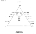
- a number of ternary solvent mixtures were prepared. The selection of the most likely solvent mixtures and ratios was in part based upon the results obtained from plotting the binary mixtures around the outer periphery of the triangular phase diagrams shown in the Figures.
- Boiling point elevation was also seen when AN was blended with different mole ratios of PC, EC and GBL. Without wishing to be bound by theory, these observations lead to the hypothesis that the AN may form complexes with the other solvent molecules in the solution which resulted in the elevation of acetonitrile boiling temperature. It was also notice that the boiling temperature increased as the conductivity (at any given temperature) of the solution decreased.
- the ESR of the ternary mixture was compared with the ESR of acetonitrile at a range of temperatures. In this way, the relative performance of the mixtures can be evaluated in a manner independent of device construction.
- the table below shows the ratio of the ESR of a ternary electrolyte device to the ESR of a corresponding acetonitrile electrolyte device, where both devices are at the temperature specified in the table. The ratio for embodiments using a binary electrolyte is also given.
- the absolute value of the ESR of the AN control device was 38.0m ⁇ at -30°C, 33.5m ⁇ at -20°C, 20.5m ⁇ at 23°C and 18.5m ⁇ at 50°C for series X.
- the absolute value of the ESR of the AN control device was 35.2m ⁇ at -30°C, 31.2m ⁇ at -20°C, 19.4m ⁇ at 23°C and 16.4m ⁇ at 50°C.
- Figure 8 demonstrates the suitability of the solvent for use at temperatures in excess of those attainable for acetonitrile, as well as illustrating the low ESR values which are attained using the ternary mixtures of the present invention. It is notable that the solvent mixtures of the present invention provide ESR's at high temperature that are similar to the ESR's which can be obtained from AN at room temperature.
- Figure 9 Shows ESR against temperature while Figure 11 shows 1/conductivity against ESR.
- the deviation in Figure 9 at elevated temperatures is believed in that case to be due to a decrease in porosity of the separator at above 90°C.
- a decrease in porosity results in an increase in the resistivity of the separator.
- Figures 8 to 11 illustrate that the solvent mixture of the present invention actually behaves in the same manner as a single solvent. Fractionating systems, with non-interacting components, would not provide the seamless electrochemical behaviour over such a wide temperature range and especially over a temperature range which includes the boiling point of AN, a major component of the mixture.
- ESR 1044.3 / 0.3948 * T + 25.852 + 6.5178 50 ⁇ ⁇ m Separator
- ESR 777.58 / 0.3948 * T + 25.852 + 6.741 50 ⁇ ⁇ m Separator
- series z ESR 649.32 / 0.3948 * T + 25.852 + 8.7202 20 ⁇ ⁇ m Separator
- ESR 1002.4 / 0.4461 * T + 45.223 + 5.2336 50 ⁇ ⁇ m Separator
- ESR 673.91 / 0.4461 * T + 45.223 + 6.7856 20 ⁇ ⁇ m Separator
- the equations were derived by plotting conductivity versus temperature and the inverse of conductivity versus ESR for each of the two solvents. A straight line fit was placed though each data set. The lines of best fit can be seen in Figures 8 and 11 . The R 2 values for the curve fit was from about 0.96 to in excess of 0.99. The linear equations were then equated using the assumption that the conductivities are equal at any given temperature. The formula was then rearranged so as to be given in terms of ESR vs. temperature. The ESR can then be multiplied by the area of the smallest opposed electrode (or the area of mutual overlap between electrodes, if there is some offset) to give a value of ESR cm 2 .
- the plot in Figure 11 can also be used to extrapolate an ESR value at a point where 1/conductivity equals zero, ie ESR at infinite conductivity.
- ESR ⁇ 5.2336m ⁇ , or when adjusted for area, 147m ⁇ cm 2 .
- ESR ⁇ 6.823m ⁇ , or when adjusted for area, 191m ⁇ cm 2 .
- the ESR ⁇ from the 3AN:1.72GBL:EC line was 6.741m ⁇ , or when adjusted for area, 189m ⁇ cm 2 .
- ESR ⁇ is a useful parameter for comparing devices.
- the boiling point of the electrolyte with 3AN:1.72GBL:EC or 3AN:2GBL:EC ternary solvent system was found to be significantly higher than that of AN alone. This electrolyte system also had good conductivity at the high and low ends of the temperature range of interest.
- TEATFB Extra salt
- the final moisture found in the electrolyte was measured through Karl Fischer titration to be ⁇ 16ppm.
- the stability of multilayer soft packaging laminate devices of the present invention was tested by thermogravimetric analysis in a DMT-Thermo Balance under a flowing air atmosphere.
- the cells take the form of a multiple layered electrode stacks.
- Temperature was ramped at 0.1 °C per minute from ambient temperature.
- the TGA shows the acetonitrile-only capacitors venting electrolyte solvent occurs between 83°C and 86°C, see Figures 27 and 28 which show the TGA results, including temperature and weight loss profiles.
- the supercapacitor cells, Figures 29 and 30 , and devices, Figures 31 and 32 , of the present invention having 3AN:1.72GBL:EC solvent systems showed no loss until over about 100°C.
- the TGA stability demonstrates the suitability of the solvents systems of the present invention to provide stable devices with desirable power windows over a wide temperature range.
- the objective of the present applicants was to determine an electrolyte which would be stable at elevated temperatures whilst retaining a usable ESR at lower temperatures (at least -20°C). Initially this was thought to be unrealisable when using acetonitrile, as the boiling point of acetonitrile is only 82°C. Trials were performed and an unusual and unprecedented trend was seen - devices with mixtures of acetonitrile managed to survive a period of time at temperatures greater than or equal to 85°C. Apparently, a boiling point elevation phenomenon was being achieved.
- the boiling point elevation due to salt is generally of the range of ⁇ 1-3°C per mole of ionic species in solution.
- the second explanation is that there is complexation or association between the solvents which leads to an increase in boiling point.
- any other soluble salts may be used, eg Lithium, Sodium, Potassium salts and the like.
- the following table shows the boiling point elevations observed in a 3AN:2GBL:EC mixture incorporating alternative electrolyte salts.
- the ternary phase diagrams summarise the results of room temperature conductivity, room temperature ESR, ESR at low temperatures and boiling point elevation for solvent mixtures of acetonitrile, propylene carbonate and ethylene carbonate; acetonitrile, propylene carbonate and ⁇ -butyrolactone; and acetonitrile, ethylene carbonate and ⁇ -butyrolactone.
- Figure 33 shows how the trends in a value of a particular property, eg boiling point, may be evaluated.
- a particular property eg boiling point
Landscapes
- Engineering & Computer Science (AREA)
- Chemical & Material Sciences (AREA)
- Chemical Kinetics & Catalysis (AREA)
- Electrochemistry (AREA)
- Power Engineering (AREA)
- Microelectronics & Electronic Packaging (AREA)
- Manufacturing & Machinery (AREA)
- General Chemical & Material Sciences (AREA)
- Electric Double-Layer Capacitors Or The Like (AREA)
- Secondary Cells (AREA)
Abstract
Description
- The invention relates to electrolytes for use in energy storage devices. In particular, the invention relates to non-aqueous electrolytes capable of high temperature operation in capacitors and supercapacitors.
- The invention has been developed primarily for supercapacitors and will be described hereinafter with reference to that application. It will be appreciated, however, that the invention is not limited to that particular field of use and is also suitable for other energy storage devices such as batteries, fuel cells, pseudocapacitors and capacitors and hybrids of one or more of these devices.
- Supercapacitors, alternatively known as ultracapacitors, electrical double layer capacitors or electrochemical capacitors, are energy storage devices that have considerably more specific capacitance than conventional capacitors. Low resistance supercapacitors are ideally suited for high power applications for mobile devices, particularly those using GSM (Global System for Mobile communication) and GPRS (General Packet Radio Service) wireless technologies.
- Supercapacitors can play a role in hundreds of applications. The energy and power storage markets, where supercapacitors reside, are currently dominated by batteries and capacitors. It is well recognised that batteries are good at storing energy but compromise design to enable high power delivery of energy. It is also well recognised that capacitors enable fast (high power) delivery of energy, but that the amount of energy delivered is very low (low capacitance). Overlaying these limitations of existing batteries and capacitors against market demand reveals the three main areas of opportunity for supercapacitors: battery replacement, devices which have higher energy density; battery complements, devices which have high power and energy densities; and capacitor replacement, devices which are smaller and not only have high power density but have high frequency response.
- Currently, the relatively high power density of supercapacitors make them ideal for parallel combination with batteries that have high energy density to form a hybrid energy storage system. When a load requires energy that is not constant, complementing the battery with a supercapacitor allows the peaks to be drawn from the charged-up supercapacitor. This reduces the load on the battery and in many cases extends the lifecycle of a battery as well as the lifetime of rechargeable batteries.
- Modem mobile devices require power systems that are capable of dealing with large fluctuations in the load. For example, a mobile telephone has a variety of modes each with a different load requirement. There is a stand-by mode, which requires low power and is relatively constant. However, this mode is periodically punctuated by the need to find the nearest base station and a signal is sent and received, requiring a higher load. In full talk mode where continuous contact to a base station is required, the load takes the form of a periodic signal where the instantaneous load is quite different from the average. A number of communication protocols exist, such as GSM and GPRS, but they are all characterized with a periodic load. The parallel supercapacitor-battery hybrid is particularly suited to this application because the power from the supercapacitor is used during the high loads that are usually short in duration and the energy from the battery can recharge the supercapacitors and supply a base load during the time of low power demand. As further miniaturization of digital wireless communication devices occur, leading to decreased battery sizes, the need for supercapacitors will increase.
- Supercapacitors also have application in the field of Hybrid Electric Vehicles (HEV). Supercapacitors can be used as an integral component of the drivetrains of these vehicles and are used as the primary power source during acceleration and for storage of energy reclaimed during regenerative braking. Such vehicles could conceivably halve a motorist's fuel bill and slash emissions by up to 90%.
- Capacitance arises when two parallel plates are connected to an external circuit and a voltage difference is imposed between the two plates, the surfaces become oppositely charged. The fundamental relationship for this separation of charges is described by the following equation

where C denotes capacitance with a unit of farads (F), ε is the permittivity with a unit of farads per metre (m), A is the area of overlap of the charged plates and L is the separation distance. The permittivity of the region between the plates is related to the dielectric constant of the material that can be used to separate the charged surfaces. - The problem with existing commercial capacitors using conventional materials is that their performance is limited by their dimensions. For example, a capacitor based around a metallized coating of a polyethylene sheet that is 50 µm thick will develop only 0.425 µF for one square metre of capacitor. Thus, over 2.3 million square metres will be required to develop 1 F.
- The supercapacitors developed by the present applicant are disclosed in detail in the applicants copending applications, for example,
PCT/AU98/00406 PCT/AU99/00278 PCT/AU99/00780 PCT/AU99/01081 PCT/AU00/00836 PCT/AU01/00553 - These supercapacitors developed by the applicant overcome the dimensionality problem described above by using as a coating material an extremely high surface area carbon.
- These supercapacitors include two opposed metal electrodes. These electrodes are coated and are maintained in a predetermined spaced apart electrically isolated configuration by an intermediate electronically insulating separator. In very broad terms, the electrodes form current collectors for the coating material, in that the metal offers significantly less resistance than the coating material. The coating is typically formed from a particulate carbon or carbons and a binder used for adhering the carbon to itself and to the associated current collector.
- The coated electrodes and intermediate separator can be either stacked or wound together and disposed within a housing that contains an electrolyte. Two current collecting terminals are then connected to and extend from respective electrodes for allowing external access to those electrodes. The housing is sealed to prevent the ingress of contaminants and the egress of the electrolyte. This allows advantage to be taken of the electrical double layer that forms at the interface between the electrodes and the electrolyte. That is, there are two interfaces, those being formed between the respective electrodes and the electrolyte. This type of energy storage device is known as a supercapacitor. Alternatively, these have been known as ultracapacitors, electrical double layer capacitors and electrochemical capacitors.
- The electrolyte contains ions that are able to freely move throughout a matrix, such as a liquid or a polymer, and respond to the charge developed on the electrode surface. The double layer capacitance results from the combination of the capacitance due to the compact layer (the layer of solvated ions densely packed at the surface of the electrode) and the capacitance due to the diffuse layer (the less densely packed ions further from the electrode).
- In supercapacitors, the compact layer is generally very thin, less than a nanometre, and of very high surface area. This is where the technological advantage for supercapacitors over conventional capacitors lies, as charge storage in the extremely thin compact layer gives rise to specific capacitances of approximately 0.1 FM-2. This is an increase by several hundred thousand-fold over conventional film capacitors. As well, the applied potential controlled, reversible nanoscale ion adsorption/desorption processes result in a rapid charging/discharging capability for supercapacitors.
- The electrode material may be constructed as a bed of highly porous carbon particles with a very high surface area. For example, surface areas may range from 100m2 per gram up to greater than 2500 m2 per gram in certain preferred embodiments. The colloidal carbon matrix is held together by a binding material that not only holds the carbon together (cohesion) but it also has an important role in holding the carbon layer onto the surface of the current collecting substrate (adhesion).
- The current collecting substrate is generally a metal foil. The space between the carbon surfaces contains an electrolyte (frequently solvent with dissolved salt). The electrolyte is a source of ions which is required to form the double layer on the surface of the carbon as well as allowing ionic conductance between opposing electrodes. A porous separator is employed to physically isolate the carbon electrodes and prevent electrical shorting of the electrodes.
- The energy storage capacity for a supercapacitor can be described by the equation

where E is the energy in joules and V is the rated or operating voltage of the supercapacitor. Apart from the voltage limitation, it is the size of the supercapacitor that controls the amount of energy stored, and the distinguishing feature of supercapacitors are the particularly high values of capacitance. Another measure of supercapacitor performance is the ability to store and release the energy rapidly; this is the power, P, of a supercapacitor and is given by
where R is the internal resistance of the supercapacitor. For capacitors, it is more common to refer to the internal resistance as the equivalent series resistance or ESR. As can be deduced from the foregoing equations, the power performance is controlled by the ESR of the entire device, and this is the sum of the resistance of all the materials, for instance, substrate, carbon, binder, separator, electrolyte and the contact resistances as well as between the external contacts. - One variable of interest in the field of supercapacitors that has yet to be fully explored is the nature of the electrolyte involved. The electrolyte is typically one or more solvents containing one or more dissolved ionic species. In many cases, the physical and electrochemical properties of electrolyte are a key factor in determining the internal resistance (ESR) of the supercapacitor and the "power spectrum" of the supercapacitor, ie the ability of the supercapacitor to provide power over various time domains or in various frequency ranges.
- The factors influencing the conductance (κ) of an electrolyte solution are described in detail in an article by B.E. Conway taken from "The Fourth International Seminar on Double Layer Capacitors and Similar Energy Storage Devices", December 12-14, 1994, held at Ocean Resort Hotel and Conference Centre, Deerfield Beach, Florida and coordinated by Florida Educational Seminars, Inc., 1900 Glades Road, Suite 358, Boca Raton, FL 33431.
- In summary, there are two principle factors which are involved in determining the conductance - these are:
- a) the concentration of free charge carriers, cations and anions; and
- b) the ionic mobility or conductance contribution per dissociated ion in the electrolyte.
- There are a number of sub factors which in turn influence these two principle factors. These are:
- The solubility of the selected salt.
- The degree of dissociation into free ions and factors such as the extent of ion-pairing of the ionic species. This in turn is influenced by the salt concentration, temperature and the dielectric constant of the solvent.
- The viscosity of the solvent, which is a temperature dependent property. As temperature increases, there is a corresponding decrease in viscosity.
- Solvents for supercapacitors can thus be designed with the following criteria in mind:
- Solvent for selected ionic species
- Degree of dissociation of cation/anion pairing in solution
- Dielectric constant
- Electron-pair donicity
- Permits high ion mobility
- Extent of solvation of free ions and radii of solvated ions
- Temperature coefficient of viscosity (ie low viscosity in the intended temperature range) and ion pairing equilibria.
- There is also the necessity for the solvent to be chemically stable. Aqueous based electrolytes, such as sulfuric acid and potassium hydroxide solutions, are often used as they enable production of an electrolyte with high conductivity. However, water is susceptible to electrolysis to hydrogen and oxygen on charge and as such has a relatively small electrochemical window of operation outside of which the applied voltage will degrade the solvent. In order to maintain electrochemical stability in applications requiring a voltage in excess of 1.5V, it is necessary to employ supercapacitor cells in series, which leads to an increase in size in relation to non-aqueous devices. Stability is important when one considers that the supercapacitors must charge and discharge many hundreds of thousands of times during the operational lifetime of the supercapacitor.
- There are of course processing requirements on the solvent also, such as cost, toxicity, purity and dryness considerations.
- Non aqueous solvents commonly used in related fields, eg batteries, can be classified as: high dielectric constant aprotic (e.g. organic carbonates), low dielectric constant with high donor number (e.g. dimethoxyethane, tetrahydrofuran or dioxolane), low dielectric constant with high polarisability (e.g. toluene or mesitylene) or intermediate dielectric constant aprotic (e.g. dimethylformamide, butyrolactone) solvents.
- However, in addition to the specific electrolyte requirements of supercapacitors mentioned above, there is also the practical consideration that supercapacitors do not operate in isolation. Rather, in use, they are in confined environments in the presence of components which generate high temperatures, and like the other components, this must be borne in mind when selecting the electrolyte solvent. Also, it needs to be borne in mind that the supercapacitors must be capable of operation at start-up at temperatures much lower (even into the sub zero range) than the high operating temperatures referred to above.
- The energy storage of batteries, in contrast to the power delivery of supercapacitors, is not critically dependent on the contribution of the electrolyte to the ESR of the cell, although even in batteries, low ESR is desirable. Solvents which have high boiling points invariably have high viscosities, and consequently, low charge mobilities at low temperatures. High boiling solvents, such as cyclic ethers and lactones can therefore be used in batteries with less regard to what would be an unacceptably high ESR in supercapacitors.
-
Figure 1 shows the relationship between literature boiling point and viscosity for a number of substances. -
Figure 2 shows the relationship between conductivity and reciprocal solvent viscosity at 25 C for 0.65M tetraethylammonium tetrafluoroborate (TEATFB) for a variety of solvents. Source: Makoto Ue, Kazuhiko Ida and Shoichiro Mori ; "Electrochemical Properties of Organic Liquid Electrolytes Based on Quaternary Onium Salts for Electrical Double-Layer Capacitors."J. Electrochem. Soc., Vol. 141, No. 11, November 1994 -
Figure 3 is a plot of ESR and reciprocal conductivity, where the conductivity is varied by changing the concentration of TEATFB in acetonitrile, and shows in a general way the relationship between ESR and conductivity for a supercapacitive cell. - These three Figures also serve to illustrate the other relationships that exist between the properties, such as boiling point and ESR, viscosity and ESR and boiling point and conductivity.
- Admixing a low boiling fluid and a high boiling fluid may appear to be an attractive option, with the low boiling, low viscosity compound providing acceptable charge mobility at the low end of the temperature range, and the high boiling component reducing in viscosity and providing charge mobility at higher temperatures. In practice, however, this approach is generally not viable because while acceptable results may be achieved at ambient temperatures, at higher temperatures the low boiling component will fractionate out. Fractionation can present a challenge to the mechanical integrity of the supercapacitor packaging.
- It is an object of the present invention to provide a non-aqueous solvent suitable for use in the energy storage device which overcomes one or more of the abovementioned disadvantages, or at least provides a commercially viable alternative.
-
EP 0 938 108 A2 - Aspects of the present invention are set out in the appended claims.
- A first example embodiment provides a non-aqueous solvent system suitable for use as an electrolyte solvent in an energy storage device, said non aqueous solvent system including:
- at least one low boiling component,
- at least one high boiling component compatible with said low boiling component; and wherein the components are selected in an amount such that said non-aqueous solvent system does not boil at the boiling point of the low viscosity solvent alone but has a boiling point greater than said low viscosity solvent alone.
- Alternatively, the invention may be described as providing a non-aqueous solvent system suitable for use in an energy storage device including a plurality of compatible component solvents each with a corresponding component solvent boiling point, and wherein the non-aqueous solvent system has at least one boiling point not corresponding to a component solvent boiling point.
- Preferably the energy storage device is a supercapacitor. More preferably, the energy storage device is a carbon based supercapacitor, that is, a supercapacitor that has carbon as a component of the electrodes.
- The energy storage devices of the present invention may be in the form of cells or devices, and may include a number of cells in series or parallel.
- Preferably, the non-aqueous solvent system is a combination of a low viscosity solvent and one or more compatible high viscosity solvents.
- Preferably the low viscosity/low boiling component is a nitrile, most preferably acetonitrile ("AN").
- The high viscosity/high boiling component is preferably one or more of a lactone, such as γ-butyrolactone ("GBL"), or an organic carbonate such as ethylene carbonate ("EC"), propylene carbonate ("PC") or mixtures or derivatives thereof.
- Preferably, the species are complexed or associated and provide a synergistic change in boiling point. Preferably, the species are in a mole ratio selected to provide an electrolyte solvent with a boiling point different from the boiling point of the low viscosity solvent.
- In one preferred embodiment, the sum of the moles of the low boiling components is less than the sum of the moles of the high boiling components. In an alternative preferred embodiment, the sum of the moles of the low boiling components is equal to the sum of the moles of the high boiling components. In another alternative preferred embodiment, the sum of the moles of the low boiling components is greater than the sum of the moles of the high boiling components.
- In a preferred embodiment, the invention provides a non-aqueous solvent system suitable for use as an electrolyte solvent in an energy storage device, said non aqueous solvent system including:
- a nitrile, at least one of a lactone or a carbonate compatible with said nitrile; and wherein the components are selected in an amount such that said non-aqueous solvent system does not boil at the boiling point of the nitrile but has a boiling point greater than the boiling point of the nitrile.
- In one particularly preferred embodiment, the invention provides a non-aqueous solvent system including acetonitrile, γ-butyrolactone, and ethylene carbonate. Even more preferably, the invention provides a non-aqueous solvent system including acetonitrile, γ-butyrolactone, and ethylene carbonate in a mole ratio of 3:2:1 to 3:1.72:1.
- In another particularly preferred embodiment, the invention provides a non-aqueous solvent system including acetonitrile, γ-butyrolactone, and propylene carbonate. Even more preferably, the invention provides a non-aqueous solvent system including acetonitrile, γ-butyrolactone, and propylene carbonate in a mole ratio of 3:2:1 to 3:1.72:1.
- In yet another particularly preferred embodiment, the invention provides a non-aqueous solvent system including acetonitrile, propylene carbonate and ethylene carbonate. Even more preferably, the invention provides a non-aqueous solvent system including acetonitrile, propylene carbonate and ethylene carbonate in a ratio of 2:1:1.
- Other preferred embodiments include 2AN:GBL:PC and 2AN:GBL:EC
- Without wishing to be limited to the particular solvents which may be used, the high boiling high viscosity solvents and/or low boiling low viscosity solvents may be selected independently from the following list. It will be understood that high boiling and low boiling, and likewise high viscosity and low viscosity, are relative terms and represent properties of the component solvents relative to one another.
- Suitable solvents include: ethylene carbonate, propylene carbonate, butylene carbonate, γ-butyrolactone, γ-valerolactone, acetonitrile, glutaronitrile, adiponitrile, methoxyacetonitrile, 3-methoxypropionitrile, N,N-dimethylformamide, N,N-dimethylacetamide, N-methypyrrolidinone, N-methyloxazolidirione, N-N'-dimethylimisazolidinone, nitromethane, nitroethane, sulfolane, dimethyl sulfoxide, trimethyl phosphate, 1,2-dimethoxyethane, tetrahydrofuran, 2-methyltetrahydrofuran, 1,3-dioxolane, 4-methyl-1,3-dioxolane, methyl formate, methyl acetate, methyl propionate, dimethyl carbonate, ethyl methyl carbonate, diethyl carbonate, methyl propyl carbonate, 1-methyl-2-pyrrolidone, 1,2-dichloroethane, sulphuryl chloride, thionyl chloride, acetyl chloride, tetrachloroethylene carbonate, benzoyl chloride, dichloroethylene carbonate, nitrobenzene, acetic anhydride, phosphorus oxychloride, benzonitrile, selenium oxychloride, propanediol-1,2-carbonate, benzylcyanide (nitrile), ethylene sulphite, iso-butyronifrile, propionitrile, phenylphosphonic difluoride, n-butyronitrile, acetone, ethyl acetate, phenylphosphonic dichloride, diethyl ether, diphenyl phosphonic chloride, trimethyl phosphate, tributyl phosphate, pyridine, hexamethyl phosphoramide and the like.
- The non-aqueous solvent systems of the present invention have a boiling point of at least 85°C, more preferably at least 90°C and even more preferably at least 100°C..
- Preferably, the non-aqueous solvent systems of the present invention further include an ionic species at least partially soluble therein, such as a salt, which may be in one preferred embodiment tetraethylammonium tetrafluoroborate. The ionic species may be present in an amount up to saturation, or in greater or lesser quantities such as 1 molar and in an amount sufficient to allow an energy storage device to function over the desired temperature range.
- Preferably, the non-aqueous solvent systems of the present invention include an ion source. The ion source may be present in an amount up to saturation at -30°C or in an amount up to saturation at any temperature, having regard to the operational requirements of the device. Tetraethylammonium tetrafluoroborate is particularly preferred. In one highly preferred embodiment, a 1 molar (at ~23°C) solution of tetraethylammonium tetrafluoroborate in the solvents of the present invention have a conductivity of at least 40 mS/cm at 85°C, more preferably at least 50 mS/cm at 85°C, even more preferably at least 55 mS/cm at 85°C and most preferably at least 60 mS/cm at 85°C. It is preferable that the non aqueous systems of the present invention are suitable four use as high temperature solvents and/or low temperature solvents.
- A second example embodiment provides a method of increasing the boiling point of a non-aqueous low boiling Tow viscosity solvent suitable for use in an energy storage device, said method including the step of combining said non-aqueous low boiling low viscosity solvent with at least one compatible high boiling high viscosity solvent.
- A third example embodiment provides a method of decreasing the viscosity of a high boiling high viscosity solvent suitable for use in an energy storage device, said method including the step of combining said high boiling high viscosity solvent with at least one compatible second liquid.
- A fourth example embodiment provides a method of increasing the useful operational temperature range of a solvent suitable for use in an energy storage device, said method including the step of combining a low boiling low viscosity solvent with at least one compatible high boiling high viscosity solvent.
- A fifth example embodiment provides a high temperature solvent suitable for use in an energy storage device, said high temperature solvent including acetonitrile, γ-butyrolactone and ethylene carbonate. In an alternative embodiment, the high temperature solvent includes acetonitrile, γ-butyrolactone and propylene carbonate. A further alternative embodiment of the high temperature solvent includes acetonitrile, propylene carbonate and ethylene carbonate.
- A sixth example embodiment provides a low temperature solvent suitable for use in an energy storage device, said low temperature solvent including acetonitrile, γ-butyrolactone and ethylene carbonate. In an alternative embodiment, the low temperature solvent includes acetonitrile, γ-butyrolactone and propylene carbonate. A further alternative embodiment of the low temperature solvent includes acetonitrile, propylene carbonate and ethylene carbonate.
- A seventh example embodiment provides an energy storage device including the non-aqueous solvent system of the present technique. In one preferred embodiment the device includes acetonitrile, γ-butyrolactone and ethylene carbonate.
- In an alternative embodiment, the energy storage device may include a solvent including acetonitrile, γ-butyrolactone and propylene carbonate. A further alternative embodiment of the energy storage device may include a solvent including acetonitrile, propylene carbonate and ethylene carbonate.
- Preferably the energy storage device is a capacitor or supercapacitor.
- An eighth example embodiment provides a method of predetermining the ESR of an energy storage device at a predetermined temperature, said method including the step of providing to the energy storage device a solvent system including at least one low boiling component, at least one high boiling component compatible with said low boiling component; and wherein the components are selected in an amount such that said non-aqueous solvent system does not boil at the boiling point of the low viscosity solvent alone but has a boiling point greater than said low viscosity solvent alone.
- A ninth example embodiment provides a method of predetermining the conductivity of an energy storage device at a predetermined temperature, said method including the step of providing to the energy storage device a solvent system including at least one low boiling component, at least one high boiling component compatible with said low boiling component; and wherein the components are selected in an amount such that said non-aqueous solvent system does not boil at the boiling point of the low viscosity solvent alone but has a boiling point greater than said low viscosity solvent alone.
- The preferred solvent systems include, but are not limited to: acetonitrile, γ-butyrolactone and ethylene carbonate; acetonitrile, γ-butyrolactone and propylene carbonate or acetonitrile, ethylene carbonate and propylene carbonate.
- A tenth example embodiment provides a supercapacitor having an ESR of no more than 1013mΩ cm2 at 23°C, preferably no more than 862mΩ cm2 at 23°C and even more preferably no more than 449mΩ cm2 at 23°C and an ESR of no more than 7840mΩ cm2 at -30°C, preferably no more than 3685mΩ cm2 at -30°C and even more preferably no more than 986mΩ cm2 at -30°C.
- Where ESR is described in terms of resistance multiplied by unit area, it will be understood by those skilled in the art that this refers to the geometric area of the current collector. Also, in those cases where the devices have differently sized current collectors, it will be understood that the resistance values relate to the area of the smallest current collector.
- An eleventh example embodiment provides a supercapacitor having an ESR of no more than 784mΩ cm2 at 85°C, preferably no more than 670mΩ cm2 at 85°C and even more preferably no more than 508mΩ cm2 at 85°C and an ESR of no more than 7840mΩ cm2 at -30°C, preferably no more than 3685mΩ cm2 at -30°C and even more preferably no more than 778mΩ cm2 at -30°C.
- A twelfth example embodiment provides a supercapacitor having an ESR of no more than 784mΩ cm2 at 85°C, preferably no more than 670mΩ cm2 at 85°C and even more preferably no more than 508mΩ cm2 and an ESR of no more than 946mΩ cm2 at 23°C and preferably no more than 862mΩ cm2 at 23°C and even more preferably no more than 449mΩ cm2 at 23°C
- A thirteenth example embodiment provides a supercapacitor having an ESR of no more than 784mΩ cm2 at 85°C and preferably no more than 670mΩ cm2 at 85°C and even more preferably no more than 508mΩ cm2 at 85°C and an ESR of no more than 946mΩ cm2 at 23°C, preferably no more than 862.4mΩ cm2 at 23°C, and even more preferably an ESR of no more than 544mΩ cm2 at 23°C and an ESR of no more than 7840mΩ cm2 at -30°C and preferably no more than 3685mΩ cm2 at -30°C and even more preferably no more than 778mΩ cm2 at -30°C.
- A fourteenth example embodiment provides a supercapacitor having an ESR of no more than 771mΩ cm2 at 80°C, preferably no more than 424mΩ cm2 at 80°C.
- A fifteenth example embodiment provides a supercapacitor having an ESR of no more than 741mΩ cm2 at 90°C, preferably no more than 412mΩ cm2 at 90°C.
- A sixteenth example embodiment provides a supercapacitor having an ESR of no more than 717mΩ cm2 at 100°C, preferably no more than 401mΩ cm2 at 100°C.
- A seventeenth example embodiment provides a supercapacitor having an ESR of no more than 675mΩ cm2 at 120°C, preferably no more than 382mΩ cm2 at 120°C.
- An eighteenth example embodiment provides a supercapacitor having an ESR of no more than 657mΩ cm2 at 130°C, preferably no more than 373mΩ cm2 at 130°C.
- A nineteenth example embodiment provides a supercapacitor having an ESR of no more than 641mΩ cm2 at 140°C, preferably no more than 366mΩ cm2 at 140°C
- The supercapacitors of the present invention may have any combination of one or more of the ESR/temperature relationships mentioned above.
- In one highly preferred embodiment, the supercapacitors have an ESR of no more than (((1044.3/(0.3948*(T)+25.852))+6.5178)*28) [Series X with 50µm Separator] and more preferably no more than (((777.58/(0.3948*(T)+25.852))+6.741)*28) [Series Z with 50µm Separator] and even more preferably no more than (((649.32/(0.3948*(T)+25.852))+8.7202)*28) [Series Z with 20µm Separator] where all units are in mΩ cm2 at temperature T(°C).
- In an alternative embodiment, where the device is a multilayer electrode stack device, as may be preferred in production cells, the ESR is preferably no more than (((1051.2/(0.3948*(T)+25.852))+13.282)*24.4) mΩ cm2.
- These values are applicable for single cell devices. Where two or more cells are connected in series, a much higher value in mΩ cm2 will be obtained.
- Preferably, the supercapacitors are high temperature supercapacitors.
- A twentieth example embodiment provides a supercapacitor having a non aqueous solvent system and an ESR at -30°C of no more than 7.4, more preferably no more than 4.5, even more preferably no more than 3.4 and most preferably no more than 2.0 times the ESR at -30°C of a supercapacitor of identical construction but which contains acetonitrile as sole solvent.
- The non aqueous solvent systems are preferably binary or ternary.
- A twenty first example embodiment provides a supercapacitor having a non aqueous solvent system and an ESR at -20°C of no more than 2.7, more preferably no more than 2.2, even more preferably no more than 2.1 times the ESR at -20°C of a supercapacitor of identical construction but which contains acetonitrile as sole solvent.
- A twenty second example embodiment provides a supercapacitor having a non aqueous solvent system and an ESR at 23°C of no more than 1.8, more preferably no more than 1.5, even more preferably no more than 1.2 times the ESR at 23°C of a supercapacitor of identical construction but which contains acetonitrile as sole solvent.
- A twenty third example embodiment provides a supercapacitor having a non aqueous solvent system and an ESR at 50°C of no more than 2.0, more preferably no more than 1.5, even more preferably no more than 1.4 times the ESR at 50°C of a supercapacitor of identical construction but which contains acetonitrile as sole solvent.
- A twenty fourth example embodiment provides a supercapacitor having a non aqueous solvent system and an ESR at -30°C of no more than 13.7, more preferably no more than 8.3,even more preferably no more than 6.4 and most preferably no more than 3.5 times the ESR at 23°C of a supercapacitor of identical construction but which contains acetonitrile as sole solvent.
- A twenty fifth example embodiment provides a supercapacitor having a non aqueous solvent system and an ESR at -20°C of no more than 4.4, more preferably no more than 3.6, even more preferably no more than 3.4 times the ESR at 23°C of a supercapacitor of identical construction but which contains acetonitrile as sole solvent.
- A twenty sixth example embodiment provides a supercapacitor having a non aqueous solvent system and an ESR at 50°C of no more than 1.6, more preferably no more than 1.3 times the ESR at 23°C of a supercapacitor of identical construction but which contains acetonitrile as sole solvent.
- A twenty seventh example embodiment provides a supercapacitor having a non aqueous solvent system and an ESR at 85°C of no more than 1.4, more preferably no more than 1.2, and most preferably no more than 1.1 times of the ESR at 23°C of a supercapacitor of identical construction but which contains acetonitrile as sole solvent.
- The supercapacitors may have any or all of the relative performance properties of the tenth to twenty seventh embodiments.
- A twenty eighth example embodiment provides method of selecting a solvent system for use in an electrical storage device including the steps of:
- selecting a plurality of potential solvents;
- preparing a primary, binary, ternary or higher order mixture of said potential solvents, optionally adding an ion source;
- determining a property of said primary, binary, ternary or higher order mixture;
- preparing a phase diagram of said mixtures; and
- identifying a solvent mixture adapted to provide a predetermined value of said property.
- Preferably, the binary, ternary or higher order mixture includes at least one high boiling high viscosity solvent and at least one low boiling low viscosity solvent.
- Preferably, the binary, ternary or higher order mixture is a combination of a low viscosity solvent and one or more compatible high viscosity solvents.
- Preferably the low viscosity solvent is a nitrile, most preferably acetonitrile.
- Preferably the high viscosity solvent is one or more of a lactone, such as γ butyrolactone, or an organic carbonate such as ethylene carbonate, propylene carbonate or derivatives thereof.
- Preferably, the given parameter is one or more of boiling point, conductivity, viscosity or ESR at a predetermined temperature.
- A twenty ninth example embodiment provides a supercapacitor preferably of a multilayer soft packaging laminate design, which has a mass loss of no more than 3% of the room temperature mass on sustained heating at 100°C, preferably a mass loss of no more than 2 % of the room temperature mass and even more preferably a mass loss of no more than 1% of the room temperature mass. Sustained heating is preferably a period in excess of 2 hours continuous use.
- A thirtieth example embodiment provides a supercapacitor, preferably of a multilayer soft packaging laminate design, which has a mass loss of no more than 2% of the room temperature mass on sustained heating at 95°C, preferably a mass loss of no more than 1 % of the room temperature mass and even more preferably a mass loss of no more than 0.5% of the room temperature mass.. Sustained heating is preferably a period in excess of 3 hours continuous use.
- A thirty first example embodiment provides a supercapacitor, preferably of soft packaging laminate design, which has a mass loss of no more than 0.5% of the room temperature mass on sustained heating at 90°C and even more preferably zero mass loss on sustained heating at 90°C. Sustained heating is preferably a period in excess of 4 hours continuous use.
- A thirty second example embodiment provides a supercapacitor having an extrapolated ESR at infinite electrolyte conductivity (ESR∞) of no more than 325mΩ cm2 more preferably no more than 189 mΩ cm2 and most preferably no more than 147mΩ cm2.
- Another example embodiment relates to a device incorporating an energy storage device of the present technique. Such devices include, but are not limited to devices such as digital wireless devices, for example, mobile telephones. Devices of the present invention also include computers, and related combination devices which may be networked conventionally or in a wireless manner. Other devices are in the form of an electrical vehicle or hybrid electrical vehicle. It will be appreciated that the devices of the present invention are especially suited to those applications where high temperature use is expected, but where design considerations would render bulky "can" type supercapacitors unsuitable.
- The energy storage devices maybe used, for example, with a GPRS communications module for a cellular telephone, a GSM module, a Mobitex module, 3G module, a PCMCIA card, a Compact Flash card, a communications card or device for a notebook computer, a laptop computer or a Tablet computer, a wireless LAN device such as a desktop or other computer or any other wireless device.
- Most preferably, the device is a supercapacitor used as part of a power source in a PCMCIA card, especially a modem or fax modem card.
- Preferably, when the energy storage devices are used with communications modules or cards, they are in the form of a supercapacitor having a plurality of supercapacitive cells. The cells are preferably connected in series and even more preferably, the cells are contained within the same package, although the cells may be contained within separate packages.
-
-
Figure 1 shows a graph of 1/boiling point against 1/viscosity for a range of solvents. -
Figure 2 shows a graph of conductivity against 1/viscosity for a range of solvents. -
Figure 3 shows a graph of ESR against 1/conductivity (as a function of TEATFB concentration at 23°C) for Series Y standard test cells with acetonitrile. -
Figure 4 shows a graph of ESR against temperature for mono solvent systems for Series Y and Series X standard test cells. -
Figures 5 shows the relationship between conductivity and ESR for a Series X standard test cell with acetonitrile. -
Figure 6 shows a graph of ESR vs 1/conductivity (obtained by varying the temperature) for a Series X standard test cell with acetonitrile. -
Figure 7 collatesFigures 6 and3 to allow comparison of the concentration and temperature effects. -
Figure 8 shows lines of best fit for conductivity against temperature for three electrolyte systems; namely 1M TEATFB in 3AN:1.72GBL:EC, 3AN:2GBL:EC and AN. -
Figure 9 shows ESR against temperature for standard test cells with 1M TEATFB in 3AN:1.72GBL:EC (Series X and Z), 3AN:2GBL:EC (Series Z) and AN (Series X). The separator is nominally 50µm thick. -
Figure 10 shows ESR against temperature for Series Z standard test cells having 1M TEATFB in 3AN:2GBL:EC and AN electrolytes. The separator is nominally 20µm thick. -
Figure 11 shows ESR against 1/conductivity for standard test cells with 1M TEATFB in 3AN:1.72GBL:EC (Series X and Z), 3AN:2GBL:EC (Series Z) and AN (Series X). The separator is nominally 50µm thick. -
Figure 12 shows ESR against 1/conductivity for Series Z standard test cells having 1M TEATFB in 3AN:2GBL:EC and AN electrolytes. The separator is nominally 20µm thick. -
Figure 13 shows ESR verses temperature for a multiple layered electrode stack in a single cell and also for two of these cells connected in series to form a two cell device. The electrolyte used was 1M TEATFB in 3AN:1.72GBL:EC. The separator was nominally 50µm thick. -
Figure 14 showsESR verses 1/conductivity for a multiple layered electrode stack in a single cell and also for two of these cells connected in series to form a two cell device. The electrolyte used was 1M TEATFB in 3AN:1.72GBL:EC. The separator was nominally 50µm thick. -
Figures 15 to 26 show phase diagrams for electrolyte mixtures. The phase diagrams show the mole ratios of the solvent mixture. The property of that particular solvent mixture is represented in boldface text, in italics or underlined. -
Figures 27 and28 show thermogravimetric analysis of a multilayered soft packaging laminate supercapacitor cell with prior art electrolyte (acetonitrile). The cell in this figure takes the form of a multiple layered electrode stack. -
Figures 29 and30 show thermogravimetric analysis of a multilayered soft packaging laminate supercapacitor cell with an electrolyte of the present invention (3AN:1.72GBL:EC). The cell in this figure takes the form of a multiple layered electrode stack -
Figures 31 and32 show thermogravimetric analysis of a multilayered soft packaging laminate supercapacitor device with an electrolyte of the present invention. -
Figure 33 shows a contour plot of boiling points for AN:PC:GBL ratios. - The present invention is described with reference to the supercapacitors developed by the present applicant and disclosed in detail in the applicants copending applications, for example,
PCT/AU98/00406 PCT/AU99/00278 PCT/AU99/00780 PCT/AU99/01081 PCT/AU00/00836 PCT/AU01/00553 - Acetonitrile (AN) is widely used as the sole solvent component of electrolyte systems because it has a high dielectric constant (38 at 20°C) and a low viscosity (0.369 cP at 20°C). A I M solution of tetraethylammonium tetrafluoroborate has a room temperature conductivity of 55mS/cm, which is around 2-5 times better than can be attained using most other single component organic solvents.
- Acetonitrile also has a low freezing point and relatively low viscosity, making it suitable for low temperature applications. However, acetonitrile boils at 82°C which means that at or above this temperature it is necessary to contain the vapour, and additional challenges need to be met in respect of ensuring the mechanical integrity of any packaging of devices which use AN at or above this temperature.
- A thermogravimetric analysis of a supercapacitor cell containing acetonitrile made without any special consideration to containing high pressure shows a sudden and irreversible weight loss at 83°C. In some applications, an upper temperature limit of 80-85°C is unsatisfactory, and higher temperatures (up to 95°C and above) are required for prolonged periods.
- As mentioned, it is important that the electrolyte has as high a conductivity and as low a contribution to device ESR as possible. High conductivity can be achieved primarily by using a low viscosity (or, in practical terms, low boiling) solvent, although in order for high conductivity, it is also necessary for the solvent to have a good dielectric constant to enable it to dissolve ionic species.
- As mentioned above, simply employing a single compound with a higher boiling solvent is not desirable for various reasons. While a number of higher boiling solvents are available with good dielectric constants, they are invariably significantly more viscous than lower boiling solvents. Further, high viscosity solutions do not exhibit appropriate conductivities until much higher temperatures (where the viscosity is reduced). Thus, while these high temperature solvents are capable of good conductance at high temperature, they have unsatisfactorily high ESRs at ambient or subzero temperatures. To illustrate the problem, at room temperature the conductivity of acetonitrile is around 55 mS/cm while that of γ-butyrolactone (GBL) is only around 18 mS/cm. Conductivity increases with temperature but the conductivity of γ-butyrolactone does not approach the room temperature conductivity of acetonitrile until the temperature reaches 130°C. To those skilled in the art, admixing the two would not appear to produce a solution to the problem as acetonitrile, which boils around 80°C would be expected to fractionate out of the mixture long before a suitable conductivity of γ-butyrolactone was achieved. Surprisingly, in the present case, such fractionation did not occur.
- In particular, the present applicant has found that solvent blends, such as a blend of a nitrile, a lactone and a carbonate, and in particular acetonitrile, γ-butyrolactone and propylene carbonate (PC) or a blend of acetonitrile, γ-butyrolactone and ethylene carbonate (EC) or a blend of acetonitrile, propylene carbonate (PC) and ethylene carbonate (EC) produce a ternary solvent that has good conductivity, (and consequently a suitably low ESR) over a good temperature operating range, with high stability at elevated operational temperature, such as 85°C.
- Without wishing to be bound by theory, it is believed that this stability at elevated temperatures is due to association between the species, i.e. rather than being a mere admixture which undergoes fractionation of the lower boiling components as temperature increases, an association between the species means that the acetonitrile does not fractionate out of the mixture. The fact that no fractionation occurred leads to the hypothesis that acetonitrile forms complexes with the other solvent molecules in the solution which results in the elevation of the acetonitrile boiling temperature, i.e. the formation of a new complex with a higher boiling point.
- A 1M Tetraethylammonium tetrafluoroborate solution in a mole ratio of 3 acetonitrile:1.72 - 2 γ-butyrolactone:1 ethylene carbonate mixture performed unexpectedly well in the tests as is illustrated in the examples. This ternary mixture had a boiling temperature of ~109°C with no fractionation of acetonitrile around its boiling point as would have been expected.
- Thermo gravimetric analysis of supercapacitor test cells and devices containing 3 acetonitrile: 1.72 γ-butyrolactone: 1 ethylene carbonate showed that the weight of the material remained constant up to at least 103°C before sample loss occurred. It was highly significant that no sample loss commenced immediately above 82°C, the boiling point of acetonitrile. Such an observation bears out the hypothesis of some intermolecular interactions taking place.
- Further, qualitative analysis of samples containing the ternary system, but with a significant mole excess of acetonitrile showed some fractionation, indicating that beyond a certain point, there was no further opportunity for complexation of the acetonitrile.
- Further investigations as to the mechanism of the temperature elevation without fractionation were conducted and in particular whether or not it involved some solvation of the ionic species in solution. Depending on the solvent and particular ionic species, the addition of a dissolved salt can generally increase boiling temperature by around 1-3°C per mole of ionic species. For example, the boiling point of another preferred ternary solvent (2AN:0.86 GBL:EC) of the present invention was around 107°C without the salt. Adding a salt to a concentration of 1 M gave a boiling point of around 108-113°C, an increase of up to 6°C. This corresponds to a rise of up to 3°C per mole of ionic species which is within the expected limits.
- By contrast, the difference between the boiling point of the mixture and the boiling point of pure acetonitrile is around 25°C. There is strong evidence that the mixture is more than merely an admixture, but rather a solution in which there is an interaction between the species.
- In order to identify those solvent systems stable over an extended lifetime at elevated temperatures (≥85°C), the following general procedure was adopted.
- Dried, recrystallised TEATFB was used throughout. Solvents used in this experiment were obtained from Merck Germany with the highest quality available i.e. Selectipur® and were run through a chromatography column packed with about 10cm of γ alumina. The moisture content in the final product was estimated by Karl Fischer titration as follows: GBL = 10ppm, PC = 5ppm, AN = 2ppm. EC was a solid and was not further purified. Once the salt was added, the mixture was shaken well until all salts were dissolved.
- Where ratios of solvents were used, these refer to mole ratios.
- Solutions of TEATFB were all 1 molar unless otherwise indicated. Where experiments are conducted on solvent only (eg, AN, or 2AN:0.86 GBL:EC) this is indicated in the text.
- The solvent mixtures were prepared with final volumes between 30 to 40ml which were sufficient for boiling point and conductivity tests.
- The conductivity of these electrolytes were measured inside a dry nitrogen atmosphere in a glove box using a handheld ULTRAMETER (Model 6P) from Nyron L Company in accordance with the recommended procedure in the operating manual.
- For boiling point determination, the sample vial was filled with about 20ml of test electrolyte plus some boiling chips and heated rapidly (~10°C /min) until the temperature reached ~75°C, then reduced to a rate rise of about 2°C/min or less, with continued monitoring of the solution.
- EC, being a solid at room temperature, was kept in a 50°C environment to ensure it remained liquid at all times. Where EC was used in conjunction with other solvents in a binary or ternary mixture, the salt was added subsequent to the combining of the solvents.
- Unless otherwise stated, a standard test cell of area 28cm2 was used to generate results. For the standard test cells, two carbon-coated electrodes were cut to a size of 28cm2 excluding terminals. The electrodes are cut such that they are 8cm x 3.5 cm. The terminals were approximately 4 cm long and were 2.5 cm from the corner along the longest edge. One electrode was folded in half such that the carbon was facing inwards. The second electrode was folded in half such that the carbon was facing outwards. This second electrode was encompassed in a membrane separator and the membrane-encased electrode was slid into the first electrode. Unless stated otherwise a 50µm polyolefin membrane was used. Those skilled in the art will appreciate that both the materials and the thickness of the membranes can be varied considerably without effecting the overall functionality of the device. The carbon layers were facing each other with a separator in between. The device was assembled so that the terminals were both pointing in the same direction.
- A multilayer soft packaging laminate was wrapped around the electrodes allowing the terminals to protrude to the outside of the packet. The packet was heat sealed leaving one end open. The cell was dried using heat and vacuum. The packet was filled with enough electrolyte to cover the electrodes and sealed. The sealed packet was pierced and taken to a tight vacuum. The packet was sealed again close to the electrode stack to complete the standard test cell.
- Examples of electrode arrangements may be found in our copending applications
PCT/AU01/01613 PCT/AU01/01590 - The cell was then cycled between a low voltage and the voltage at which the cell was to be used. Electrical testing was then performed. ESR measurements were taken, at voltage as per the industry standard, which in the present case is 1.8V, at 1kHz. Capacitance was measured using a discharge current of 0.2A.
- Where the following data is dependent upon the construction of the supercapacitor, such data is given as being either "Series X", which has a nominal 4.5µm carbon layer; "Series Z" which has a nominal 7.3µm carbon layer thickness; "Series Y", which has a nominal 10µm carbon layer thickness; and "Series W" which has a 13.5µm coating thickness. The density of the series is as follows: Series X - 0.22mg/cm3; Series Y - 0.33mg/cm3; Series W - 1.12mg/cm3 and Series Z - 0.35mg/cm3. Because the series data relate to variations in the construction of the supercapacitor Series X data should only be compared with other Series X data and so on. Control data obtained for acetonitrile in all series enables the relative results to be standardised and compared. The cells which take the form of a multiple layered electrode stacks invariably used a coating thickness of nominally 6µm and a density of approximately 0.35mg/cm3
- Experimental errors in observed values have not been quoted here, although those skilled in the art will be familiar with the precision and accuracy with which such values are normally determined.
- Descriptions of the construction of multilayered electrode stack devices are disclosed in our copending application
PCT/AU01/01613 - The standard test cell, for a nominally 6µm thick coating and nominally 50µm thick separator membrane, has a volume in the order of 1.23x10⁻⁶ m3 and a weight of 1.76g including the multilayer packaging laminate.
- The standard test cell, for a nominally 6µm thick coating and nominally 50µm thick separator membrane, has a volume in the order of 3.03x10⁻⁷ m3 and a weight of 0.43g neglecting the multilayer packaging laminate.
- The cell comprised of a multiple layered electrode stack, for a nominally 6µm thick coating and nominally 50µm thick separator membrane, has a volume in the order of 8.62x 10⁻⁷ m3 and a weight of 0.97g including the multilayer packaging laminate.
- The cell comprised of a multiple layered electrode stack, for a nominally 6µm thick coating and nominally 50µm thick separator membrane, has a volume in the order of 3.19x10⁻⁷ m3 and a weight of 0.39g neglecting the multilayer packaging laminate.
- The two cell device comprised of two multiple layered electrode stacks connected in series, for a nominally 6µm thick coating and nominally 50µm thick separator membrane, has a volume in the order of 1.72x10⁻⁶ m3 and a weight of 1.94g including the multilayer packaging laminate.
- The two cell device comprised of two multiple layered electrode stacks connected in series, for a nominally 6µm thick coating and nominally 50µm thick separator membrane, has a volume in the order of 6.37 x 10⁻⁶ m3 and a weight of 0.78g neglecting the multilayer packaging laminate.
- It will be obvious to those skilled in the art that altering the physical properties, including the density of the coating, the thickness of the coating, the density of the separator, the thickness of the separator and or the density of the multilayer soft packaging laminate or the thickness of the multilayer soft packaging laminate or the thickness or density of the current collector will alter the volume and thickness of the cells similarly.
- As mentioned earlier, acetonitrile is an extremely useful electrolyte solvent. It has a very low viscosity and a very high dielectric constant. Both these attributes combine to make an acetonitrile electrolyte which has a very high conductivity. The downside of using acetonitrile as the electrolyte in a supercapacitor is the fact that it boils at around 80°C which means that there are additional containment problems to address if the supercapacitor is to be used at high temperatures.
- In order to identify an alternate solvent with a comparable conductivity, the parameters for likely mono solvent systems were established before focussing on binary and ternary solvent systems. Three different solvents were mixed with tetraethylammonium tetrafluoroborate up to saturation or 1M, which ever is the lesser. These mixtures were then purified in the usual method and tested in a variety of methods including electrical testing, in standard test cells, as well as conductivity measurements over a range of temperatures.
- Three main electrolyte solvents were tested: γ-butyrolactone (GBL), propylene carbonate (PC) and ethylene carbonate (EC). Acetonitrile was also used as a control.
- The relevant physical properties of the solvents in question are as follows:
Solvent Melting Point/Boiling Point (°C) Dielectric Constant Density (g/cm3) at 20°C Viscosity (cP) at 25°C Acetonitrile (AN) -46/82 38 (at 20°C) 0.78 0.369 γ-butyrolactone (GBL) -44/204-6 39 (at 25°C) 1.13 1.17 Propylene Carbonate (PC) -48/242 65 (at 25°C) 1.21 2.8 (20°C) Ethylene Carbonate (EC) 35-8/247-9 95 (at 25°C) 1.41 1.92 (40°C) -
Acetonitrile Temperature (deg C) Conductivity (mS/cm) 1M TEATFB -20 32.8 0 48.1 25 59.6 50 70.2 75 79.7 Figure 4 shows ESR versus Temperature for PC, GBL and AN. In order to illustrate the principle further,Figures 5 and6 show plots of ESR against conductivity and ESR against 1/conductivity respectively for AN. - The following data was obtained in a standard test cell:
-
Electrolyte ESR (mΩ)23°C Capacitance (0.2A) (F) 23°C AN 1 M TEATFB 25.1 0.72 -
Electrolyte ESR (mΩ)23°C Capacitance (0.2A) (F) 23°C AN 1M TEATFB 20.5 0.52 - γ-Butvrolactone (GBL): The saturation point for this liquid, with respect to tetraethylammonium tetrafluoroborate, is around 0.92M at room temperature (23°C). The conductivity measurements over a range of temperatures is shown in the following table:
γ- Butyrolactone Temperature (Deg C) Conductivity (mS/cm) 0.92M -5.6 9.0 0.1 10.5 23.6 16.9 85.2 33.2 131.0 51.0 - It can be seen from this table that the conductivity of the solution does not rival the room temperature conductivity of 1M acetonitrile (55mS/cm) until over 130°C. This is most likely due to the increased viscosity of the GBL as compared to AN. The test cells at room temperature (below) also show a proportionally higher ESR than the control.
-
Electrolyte ESR (mΩ) 23°C Capacitance (0.2A) (F) 23°C AN 1M TEATFB 25.1 0.72 GBL 0.92M TEATFB 62.1 0.70 - Propylene Carbonate (PC): Propylene carbonate can solvate slightly more than one molar of tetraethylammonium tetrafluoroborate. The saturation limit is around 1.2M at room temperature. The conductivity data was found to be as follows:
PC 1M Temperature (Deg C) Conductivity (mS/cm) -22.5 1.3 0 8.0 25 13.8 85 30.2 180 55.1 - Like GBL, propylene carbonate does not have a conductivity anywhere near the room temperature conductivity of AN until it reaches 180°C. The averages for the ESR of the test cells were found to be:
-
Electrolyte ESR (mΩ) 23°C Capacitance (0.2A) 23°C AN 1M TEATFB 25.1 0.72 PC 1M TEATFB 65.4 - Interestingly the dielectric constant of propylene carbonate is higher than acetonitrile (almost double in fact) which should allow it to dissociate more salt. While such a characteristic is desirable the main drawback with using propylene carbonate, which corresponds to the higher ESR, is its exorbitantly high viscosity : PC is over 7 times more viscous than AN. The main benefit with PC is its 242°C boiling point.
- Ethylene Carbonate (EC) is slightly different from the other solvent systems used in that it is a solid at ambient temperatures. Consequently, it was not possible to obtain data for EC alone at temperatures below about 35-40°C.
- The ESR of Series X and Series Y cells is given in the following table and a plot of ESR against temperature is shown in
Figure 4 .ESR at specified temp (mΩ) -20°C 23° C 50°C 85°C 1M TEATFB in AN 33.5 20.5 18.5 1M TEATFB in PC 293.9 65.4 40.0 0.92M TEATFB in GBL 62.1 44.1 EC Solid Solid - Following a thorough analysis of the boiling points and conductivities of various combinations of acetonitrile (AN), ethylene carbonate (EC), γ-butyrolactone (GBL), and propylene carbonate (PC), binary mixtures of each were prepared to investigate their suitability for high temperature application.
- The main binary systems investigated were those with a combination of a low boiling, non viscous liquid, and a higher boiling more viscous liquid. In particular, these were: AN:GBL, AN:0.86 GBL, AN:PC, and AN:EC
- The electrolytes were made up as 1M (tetraethylammonium tetrafluoroborate) TEATFB solutions and underwent electrical performance and stability testing across a range of -20°C to 95°C.
- Control data for AN is given and those skilled in the art will readily appreciate that this value can be used to standardize the data between Series X, Series Y and Series Z and allow a direct comparison of the quantitative differences between the two data sets, should this be desired.
Solution Conductivity (mS/cm) Tested temp (°C) Boiling Point (°C) 0.86GBL:AN 31.3 29.0 108-110 GBL:AN 30.6 23.8 106 0.86GBL:2AN 38.1 26.4 97 GBL:2AN 36.9 23.0 97 1.72GBL:AN 25.9 26.9 125-126 2GBL:AN 24.8 23.0 121 PC:AN 27.0 26.2 112 PC:2AN 26.7 26.4 112 2PC:AN 21.3 27.3 131-132 PC:2.5AN 36.0 28.9 96 PC:3AN 37.7 29.4 92 EC:AN 28.5 26.2 110-113 EC:2AN 43.3 26.2 93 2EC:AN 28.5 27.1 113 EC:1.5AN 32.0 30.5 104 - The ESR and Capacitance of supercapacitors incorporating the solvent systems of the present invention were investigated at 23°C. The control data and results are summarised below and are plotted on the phase diagrams and in
Figure 5 . -
Electrolyte ESR (mΩ) 23°C Capacitance (0.2A) (F) 23°C AN 1M TEATFB 20.5 0.52 -
Electrolyte ESR (mΩ) 23°C Capacitance (0.2A) (F) 23°C AN 1M TEATFB 25.1 0.72 -
Electrolyte ESR (mΩ) 23°C Capacitance (0.2A) (F) 23°C AN 1M TEATFB 19.4 0.74 -
Electrolyte ESR (mΩ) Capacitance (F) AN: 0.86GBL 1M TEATFB 26.8 0.40 -
Electrolyte ESR (mΩ) Capacitance (F) AN:GBL 1M TEATFB: 31.9 0.75 -
Electrolyte ESR (mΩ) Capacitance (F) AN: 0.86GBL 1M TEATFB 27.5 0.75 -
Electrolyte ESR (mΩ) Capacitance (F) AN:EC 1M TEATFB 35.9 0.38 -
Electrolyte ESR (mΩ) Capacitance (F) AN:PC 1M TEATFB 38.3 0.32 -
Electrolyte ESR (mΩ) Capacitance (F) AN:PC 1M TEATFB 41.6 0.48 - The results for the mixtures were plotted on phase diagrams, as shown in
Figures 15 to 26 . - The ESR of various binary mixtures was measured at a range of temperatures, and the results are shown in the following table.
-
Data Series ESR at specified temp (mΩ) Electrolytes: -20°C 23°C 85°C Series X AN: 0.86GBL 70.7 26.8 23.4 Series Z AN: 0.86GBL 27.5 Series Z AN:GBL 65.1 31.7 21.7 Series X AN:EC 230.3 35.9 28.3 Series X AN:PC 38.3 Series Y AN:PC 41.6 27.3 - The conductivity of AN:0.86GBL and AN:GBL solutions with 1M TEATFB was determined for a range of temperatures. The results are shown in the following table.
AN: 0.86GBL Temperature (°C) Conductivity (mS/cm) 1M TEATFB -30 13.4 -20 17.0 0 24.3 23 31.8 50 42.4 85 55.2 AN:GBL Temperature (°C) Conductivity (mS/cm) 1M TEATFB -30 10.9 -20 13.3 0 19.8 23 30.6 50 39.4 85 52.5 - A number of ternary solvent mixtures were prepared. The selection of the most likely solvent mixtures and ratios was in part based upon the results obtained from plotting the binary mixtures around the outer periphery of the triangular phase diagrams shown in the Figures.
- The conductivity and boiling point of the electrolytes prepared are shown in the following table:
Solvent system (1M TEATFB) Conductivity (mS/cm) Tested temp (°C) Boiling Point (°C) PC:AN:0.86GBL 23.2 30.8 132 PC:AN:GBL 23.0 23.0 122-124 PC:2AN:0.86GBL 29.0 28.0 101-105 PC:2AN:GBL 28.3 24.2 106-108 3AN:0.86GBL:PC 32.4 31.0 104 3AN:GBL:PC 32.6 23.0 98 3AN:1.72GBL:PC 28.7 29.9 109 3AN:2GBL:PC 28.1 23.9 109 6AN:0.86GBL:2PC 35.1 28.9 98 6AN:GBL:2PC 34.3 23.0 96 EC:2AN:0.86GBL 30.5 27.7 108-113 EC:2AN:GBL 31.4 23.8 108 0.86GBL:EC:AN 25.6 29.9 130 GBL:EC:AN 26.4 23.0 118-120 3AN:1.72GBL:EC 30.5 32.1 109 3AN:2GBL:EC 30.9 23.7 107-110 3AN:0.86GBL:2EC 30.0 32.3 108-110 3AN:GBL:2EC 31.6 23.2 107 EC:AN:PC 22.4 27.8 106-107 PC:EC:2AN 28.3 29.3 108-110 3AN:EC:PC 31.7 28.7 101-104 4.5AN:2EC:PC 32.0 28.7 *104 6AN:2PC:EC 34.4 29.0 *100 - Those entries in the table above marked with an asterisk exhibited some apparent fractionation before reaching the stated boiling point. Without wishing to be bound by theory, it is believed this was as a result of excess acetonitrile in those mixtures over and above that required to provide the true high boiling ternary mixture.
- Boiling point elevation was also seen when AN was blended with different mole ratios of PC, EC and GBL. Without wishing to be bound by theory, these observations lead to the hypothesis that the AN may form complexes with the other solvent molecules in the solution which resulted in the elevation of acetonitrile boiling temperature. It was also notice that the boiling temperature increased as the conductivity (at any given temperature) of the solution decreased.
- From the results above, some promising systems were chosen for ESR and capacitance testing because they appear to have the temperature range and conductivities to meet ESR requirements across the temperature range from -30°C to 95°C.
- The following results were obtained with standard test cells.
-
Solvent System 23°C ESR (mΩ) Capacitance (F) 3AN:1.72GBL:PC 1M TEATFB 31.7 0.44 3AN: 0.86GBL:2EC 1M TEATFB 30.3 0.46 2AN:PC:EC 1M TEATFB 34.5 0.42 2AN: 0.86GBL:PC 1M TEATFB 34.0 0.41 2AN: 0.86GBL:EC 1M TEATFB 31.5 0.43 3AN:1.72GBL:EC 1M TEATFB 30.5 0.42 -
Solvent System 23°C ESR (mΩ) Capacitance (F) 3AN:2GBL:PC 1M TEATFB 33.8 0.71 3AN:GBL:2EC 1M TEATFB 31.6 0.70 2AN:GBL:PC 1M TEATFB 34.9 0.70 2AN:GBL:EC 1M TEATFB 31.6 0.72 3AN:2GBL:EC 1M TEATFB 26.7 0.72 - A number of trials were also conducted using Series Y standard test cells. Series X and Series Y results are compared in the following table. All averages are based on 2-5 cells.
ESR and Capacitance 23°C ESR (mΩ) Capacitance (F) ESR (mΩ) Capacitance (F) Electrolyte: Series Y Series Y Series X Series X 2AN: 0.86GBL:EC Average 41.4 0.8 31.5 0.48 AN:PC: 0.86GBL Average: 48.5 0.78 - Series W and Series Z results for standard test cells are compared in the following table. Averages are based on results from 5 cells.
ESR and Capacitance 23°C ESR (mΩ) Capacitance (F) ESR(mΩ) Capacitance (F) Electrolyte: Series W Series W Series Z Series Z 2AN:GBL:EC 30.0 1.13 31.6 0.72 AN:PC: GBL 39.1 1.32 32.8 0.70 - The ESR of the ternary mixtures were measured at varying temperatures. The results are the average of 3-5 standard test cells in Series X and Series Z and are shown in the tables below and in
Figure 8 . -
Solvent System ESR at specified temp (mΩ) -30°C -20°C 23° C 50°C 85°C 2AN:0.86GBL:EC 135.0 74.5 31.5 27.1 26.3 2AN:0.86GBL:PC 187.9 77.9 34.0 26.4 25.3 2AN:PC:EC 149.2 90.9 34.5 29.8 28.5 3AN:1.72GBL:EC 130.6 70.6 30.5 26.0 25.5 3AN:0.86GBL:2EC 280.1 73.8 30.3 26.4 24.6 3AN:1.72GBL:PC 170.4 73.1 31.7 26.9 24.6 -
Solvent System ESR at specified temp (mΩ) -30°C -20°C 23° C 50°C 85°C 2AN:GBL:EC 85.64 74.05 35.05 32.83 23.3 2AN:GBL:PC 89.79 59.02 34.79 33.59 22.3 3AN:2GBL:EC 64.3 53.8 26.7 22.5 20.9 3AN:GBL:2EC 83.80 70.10 31.57 29.72 23.1 3AN:2GBL:PC 96.46 73.15 32.71 31.66 22.28 - The ESR of the ternary mixtures at varying temperatures for Series X and Series Z were adjusted for geometric area and a value of ESR multiplied by square cm of current collector (ESRx28cm2)at different temperatures was obtained and is shown below in the table.
-
Boiling Point (°C) Solvent System ESRxArea at specified temp (mΩ cm2) -30°C -20°C 23° C 50°C 85°C 108-113 2AN:0.86GBL:EC 3763 2117 862 784 706 101-105 2AN:0.86GBL:PC 5253 2195 941 706 706 108-110 2AN:PC:EC 4155 2509 941 862 784 109 3AN:1.72GBL:EC 3684 1960 862 706 706 108-110 3AN:0.86GBL:2EC 7840 2038 862 706 706 109 3AN:1.72GBL:PC 4782 2038 862 784 706 -
Boiling Point (°C) Solvent System ESRxArea at specified temp (mΩ cm2) -30°C -20°C 23° C 50°C 85° C 108 2AN:GBL:EC 2489.2 2113.4 1012.6 907.2 637.1 107-110 3AN:2GBL:EC 1800.4 1506.4 747.6 630 585.2 107 3AN:GBL:2EC 2230.8 1876.7 901.7 821.1 606.8 109 3AN:2GBL:PC 2812.5 2097.9 945.4 880.0 619.3 - The ESR of the ternary mixture was compared with the ESR of acetonitrile at a range of temperatures. In this way, the relative performance of the mixtures can be evaluated in a manner independent of device construction. The table below shows the ratio of the ESR of a ternary electrolyte device to the ESR of a corresponding acetonitrile electrolyte device, where both devices are at the temperature specified in the table. The ratio for embodiments using a binary electrolyte is also given. For reference, the absolute value of the ESR of the AN control device was 38.0mΩ at -30°C, 33.5mΩ at -20°C, 20.5mΩ at 23°C and 18.5mΩ at 50°C for series X. For the series Z device, the absolute value of the ESR of the AN control device was 35.2mΩ at -30°C, 31.2mΩ at -20°C, 19.4mΩ at 23°C and 16.4mΩ at 50°C.
-
Boiling Point (°C) Solvent System ESR of ternary/ESR of AN -30°C -20°C 23° C 50°C 108-113 2AN: 0.86GBL:EC 3.5 2.2 1.5 1.5 101-105 2AN:0.86GBL:PC 4.9 2.3 1.7 1.4 108-110 2AN:PC:EC 3.9. 2.7 1.7 1.6 109 3AN:1.72GBL:EC 3.4 2.1 1.5 1.4 108-110 3AN:0.86GBL:2EC 7.4 2.2 1.5 1.4 109 3AN:1.72GBL:PC 4.5 2.2 1.5 1.5 108-110 AN:0.86GBL 2.1 1.2 -
Boiling Point (°C) Solvent System ESR of ternary/ESR of AN -30°C -20°C 23° C 50° C 108 2AN:GBL:EC 2.4 2.4 1.8 2.0 106-108 2AN:GBL:PC 2.8 2.5 1.8 2.0 107-110 3AN:2GBL:EC 2.0 2.2 1.6 1.7 107 3AN:GBL:2EC 2.2 2.1 1.6 1.7 109 3AN:2GBL:PC 2.8 2.4 1.7 1.8 106 AN:GBL 2.4 2.1 1.6 1.8 - It is not possible to compare the ESR of ternary electrolytes against AN at temperatures much in excess of the boiling point of AN. However, in order to be able to compare the relative performances of all the ternary electrolytes (and the AN:0.86GBL, and AN:GBL binary mixtures) at elevated temperatures, they have been compared in the following tables against the ESR of AN at room temperature for series X (where the absolute value of the ESR of the AN control device at room temperature was 20.5mΩ) and series Z (where the absolute value of the ESR of the AN control device at room temperature was 19.4mΩ).
-
Boiling Point (°C) Solvent System ESR of ternary/ESR of AN @ room temp -30°C -20°C 23° C 50°C 85°C 108-113 2AN:0.86GBL:EC 6.6 3.6 1.5 1.3 1.3 101-105 2AN:0.86GBL:PC 9.2 3.8 1.7 1.3 1.2 108-110 2AN:PC:EC 7.3 4.4 1.7 1.5 1.4 109 3AN:1.72GBL:EC 6.4 3.4 1.5 1.3 1.2 108-110 3AN:0.86GBL:2EC 13.7 3.6 1.5 1.3 1.2 109 3AN:1.72GBL:PC 8.3 3.6 1.5 1.3 1.2 108-110 AN:0.86GBL 3.4 1.2 1.1 -
Boiling Point (°C) Solvent System ESR of ternary/ESR of AN @ room temp -30°C -20°C 23° C 50°C 85°C 106-108 2AN:GBL:PC 5.1 4.0 1.8 1.6 1.2 106-108 2AN:GBL:PC 5.1 4.0 1.8 1.6 1.2 107-110 3AN:2GBL:EC 3.5 3.5 1.6 1.5 1.1 107 3AN:GBL:2EC 4.0 3.4 1.6 1.5 1.1 109 3AN:2GBL:PC 5.0 3.7 1.7 1.6 1.1 106 AN:GBL 4.3 3.2 1.6 1.5 1.2 - Trials of the 3AN:1.72GBL:EC and 3AN:2GBL:EC ternary mix electrolytes demonstrated desirable ESR's across all temperature ranges. Most importantly, these cells appear to be quite stable at temperatures above 85°C .
- The relationship between conductivity and temperature for AN and 3AN:1.72GBL:EC and 3AN:2GBL:EC is shown in
Figure 8 . The continuing relationship between conductivity and ESR can be seen to continue smoothly to temperatures in excess of 100°C. -
Figure 8 demonstrates the suitability of the solvent for use at temperatures in excess of those attainable for acetonitrile, as well as illustrating the low ESR values which are attained using the ternary mixtures of the present invention. It is notable that the solvent mixtures of the present invention provide ESR's at high temperature that are similar to the ESR's which can be obtained from AN at room temperature. -
Figure 9 Shows ESR against temperature whileFigure 11 shows 1/conductivity against ESR. The deviation inFigure 9 at elevated temperatures is believed in that case to be due to a decrease in porosity of the separator at above 90°C. A decrease in porosity results in an increase in the resistivity of the separator. - In combination,
Figures 8 to 11 illustrate that the solvent mixture of the present invention actually behaves in the same manner as a single solvent. Fractionating systems, with non-interacting components, would not provide the seamless electrochemical behaviour over such a wide temperature range and especially over a temperature range which includes the boiling point of AN, a major component of the mixture. - When measured in a 28cm2 test cell, ESR and temperature for the high temperature electrolyte 3AN:1.72GBL:EC were found to be related by the following equation:


- Where the temperature T is in degrees Celsius and the ESR is in mΩ.
- The relationship between ESR and temperature for AN (calculated) was also quantified and found to be:


- The equations were derived by plotting conductivity versus temperature and the inverse of conductivity versus ESR for each of the two solvents. A straight line fit was placed though each data set. The lines of best fit can be seen in
Figures 8 and11 . The R2 values for the curve fit was from about 0.96 to in excess of 0.99. The linear equations were then equated using the assumption that the conductivities are equal at any given temperature. The formula was then rearranged so as to be given in terms of ESR vs. temperature. The ESR can then be multiplied by the area of the smallest opposed electrode (or the area of mutual overlap between electrodes, if there is some offset) to give a value of ESR cm2. The more general equation is written thus:


where the units for the above equations are: mΩ cm2 - The plot in
Figure 11 can also be used to extrapolate an ESR value at a point where 1/conductivity equals zero, ie ESR at infinite conductivity. Using the lines of best fit fromFigure 11 , for the AN series X line an ESR at infinite conductivity, ESR∞ = 5.2336mΩ, or when adjusted for area, 147mΩ cm2. Similarly, for AN series Y (Figure 7 ), ESR∞= 6.823mΩ, or when adjusted for area, 191mΩ cm2. The ESR∞ from the 3AN:1.72GBL:EC line was 6.741mΩ, or when adjusted for area, 189mΩ cm2. ESR∞ is a useful parameter for comparing devices. - Similar equations can be constructed for other electrolyte systems, and for differing cell constructions. For example,
Figures 7 ,9 ,11 ,13 and14 illustrate differences in observed values which are effected by supercapacitor construction. - For example, in a standard test cell as disclosed above, the variation in separator thickness attributed to moving between a 20µm separator and a 50µm separator.
50µm Separator Electrolyte Equation 1M AN ESR = (((1002.4/(0.4461 *T+45.223))+5.2336)*28)mΩ cm2 Series X 1M 3AN:2GBL:EC ESR = (((646.94/(0.4009*T+22.646))+8.8613)*28)mΩ cm2 Series Z 1M 3AN:1.72GBL:EC (1) ESR = (((777.58/(0.3948*(R4)+25.852))+6.741)*28) mΩ cm2 (1) Series Z (2) Series X (2) ESR =(((1044.3/(0.3948*(N4)+25.852))+6.5178)*28) mΩ cm2 20µm Separator Electrolyte Equation 1M AN ESR = (((673.91/(0.4461 *T+45.223))+6.7856)*28) mΩ cm2 Series Z 1M 3AN:2GBL:EC ESR = (((501.19/(0.4009*T+22.646))+9.9452)*28) mΩ cm2 Series Z 1M 3AN:1.72GBL:EC ESR = (((649.32/(0.3948*(B4)+25.852))+8.7202)*28) mΩ cm2 Series Z 1M 3AN:1.72GBL:EC Multiple Layered Electrode Stack Cells Single cell: ESR = (((1051.2/(0.3948*(T)+25.852))+13.282)*24.4) mΩ cm2 Two cells connected in series: ESR =(((2045/(0.3948*(T)+25.852))+13.009)*48.8) mΩ cm2 - The boiling point of the electrolyte with 3AN:1.72GBL:EC or 3AN:2GBL:EC ternary solvent system was found to be significantly higher than that of AN alone. This electrolyte system also had good conductivity at the high and low ends of the temperature range of interest.
- Based on the boiling point and performance in the test cell, an extensive analysis of the results revealed that the 1M TEATFB in 3AN:1.72GBL:EC - 3AN:2GBL:EC was the preferred choice and this electrolyte solution was prepared to use in further testing.
- By way of example, the following shows the method of calculation of the actual values used for the production of electrolyte as follows:

- Extra salt (TEATFB) added ∼ 15.876g to make total salt concentration in mixture to 1 Molar TEATFB.
- The moisture in this electrolyte was removed by putting approximately 100g of γ alumina into this electrolyte and stirring well for one minute. The alumina was allowed to settle before being filtered out.
- The final moisture found in the electrolyte was measured through Karl Fischer titration to be ~ 16ppm.
- The stability of multilayer soft packaging laminate devices of the present invention was tested by thermogravimetric analysis in a DMT-Thermo Balance under a flowing air atmosphere. For this test the cells take the form of a multiple layered electrode stacks.
- Temperature was ramped at 0.1 °C per minute from ambient temperature.
- The TGA shows the acetonitrile-only capacitors venting electrolyte solvent occurs between 83°C and 86°C, see
Figures 27 and28 which show the TGA results, including temperature and weight loss profiles. By contrast, the supercapacitor cells,Figures 29 and30 , and devices,Figures 31 and32 , of the present invention having 3AN:1.72GBL:EC solvent systems showed no loss until over about 100°C. - In combination with the low ESR over a wide temperature range, the TGA stability demonstrates the suitability of the solvents systems of the present invention to provide stable devices with desirable power windows over a wide temperature range.
- As stated earlier, the objective of the present applicants was to determine an electrolyte which would be stable at elevated temperatures whilst retaining a usable ESR at lower temperatures (at least -20°C). Initially this was thought to be unrealisable when using acetonitrile, as the boiling point of acetonitrile is only 82°C. Trials were performed and an unusual and unprecedented trend was seen - devices with mixtures of acetonitrile managed to survive a period of time at temperatures greater than or equal to 85°C. Apparently, a boiling point elevation phenomenon was being achieved.
- There are two non-limiting theories on how this boiling point elevation could be realised. The first is that the elevation is a manifestation of the effect of salt in a solution. This is a well-established theory. The boiling point elevation due to salt is generally of the range of ~1-3°C per mole of ionic species in solution. The second explanation is that there is complexation or association between the solvents which leads to an increase in boiling point.
- An experiment to distinguish between these explanations was conducted using one mixture with and without salt. Select results have been reproduced below.
Solution Boiling Point °C 2AN:0.86GBL:EC + 1M TEATFB 108-113 2AN:0.86GBL:EC (Solvent only) 107 AN (solvent only) 82 - It can be seen from the results above that the effect of adding salt to the 2AN:0.86GBL:EC mixture is to increase boiling point by about 1-6°C. That is up to 3°C per mole of ionic species. This is within the theoretical limits of what has previously been seen on the addition of salt.
- By contrast the difference between the mixture of2AN:0.86GBL:EC and the pure acetonitrile is 25°C. If the mixture is not an actual solution then one would expect to see some fractionation at 82°C. The fact that this is not seen implies that there is indeed a solvation effect on the acetonitrile.
- Hence it implies that, whilst the addition of salt does raise the boiling point somewhat, the main boiling point elevation is due to the mixture effect.
- While the invention has been illustrated with TEATFB, any other soluble salts may be used, eg Lithium, Sodium, Potassium salts and the like. The following table shows the boiling point elevations observed in a 3AN:2GBL:EC mixture incorporating alternative electrolyte salts.
Boiling point of alternative salts in 3AN:2GBL:ECSalt in 3AN:2GBL:EC Boiling point (°C) Solvent only 104-106 1M Tetrabutylammonium Perchlorate 107 1M Tetrabutylammonium Tetrafluoroborate 105-107 1M Tetrabutylammonium Hexafluorophosphate 107 1M Triethylmethylammonium Tetrafluoroborate 108 0.5 M Lithium Tetrafluoroborate 106 - The ternary phase diagrams summarise the results of room temperature conductivity, room temperature ESR, ESR at low temperatures and boiling point elevation for solvent mixtures of acetonitrile, propylene carbonate and ethylene carbonate; acetonitrile, propylene carbonate and γ-butyrolactone; and acetonitrile, ethylene carbonate and γ-butyrolactone.
-
Figure 33 shows how the trends in a value of a particular property, eg boiling point, may be evaluated. By creating a "contour plot" in which experimental date of equal value (ie equal boiling point) are joined, it becomes possible to predict other intermediate solvent compositions which may have that boiling point, or determine which other compositions may have a suitable boiling temperature. While this has been exemplified for boiling point elevation in AN:PC:GBL, those skilled in the art will appreciate that it can be applied equally to other solvent systems, and to other properties which depend upon the composition of the electrolyte, such as ESR and conductivity. - The ternary phase diagrams clearly show that the attempt to find a high temperature electrolyte is a trade off between high boiling point/high viscosity (and resultant low conductivity) on the one hand and high conductivity with a low boiling point on the other. Unfortunately the ultra high temperature electrolytes have low conductivity because they have a high viscosity, as discussed in the introduction and shown in
Figures 1 to 3 . - The unexpected synergy of the solvent components, apparently as a result of complexation, allows for the selection of electrolyte solvents which have a better performance profile over a wide range of components than would be predicted from looking at the component solvents alone.
Claims (34)
- A non-aqueous solvent system suitable for use as an electrolyte solvent in an energy storage device, said non-aqueous solvent system including, by molar ratios: 1 part propylene carbonate (PC) or ethylene carbonate (EC), 2-3 parts acetonitrile (AN) and 0.43 to 2 parts γ-butyrolactone (GBL).
- A non-aqueous solvent system according to claim 1 including, by molar ratios: 3 parts acetonitrile (AN); 1.72 to 2 parts γ-butyrolactone (GBL); and 1 part ethylene carbonate (EC).
- A non-aqueous solvent system according to claim 1 including by molar ratios: 3 parts acetonitrile (AN); 1.72 to 2 parts γ-butyrolactone (GBL); and I part propylene carbonate (PC).
- A non-aqueous solvent system according to any one of the preceding claims having a boiling point of at least 85°C.
- A non-aqueous solvent system according to any one of the preceding claims having a boiling point of at least 90°C.
- A non-aqueous solvent system according to any one of the preceding claims having a boiling point of at least 100°C.
- A non-aqueous solvent system according to any one of the preceding claims having a boiling point of at least 106°C.
- A non aqueous electrolyte for an energy storage device including:a non aqueous solvent system according to any one of the preceding claims; andan ionic species at least partially soluble therein.
- A non aqueous electrolyte according to claim 8 wherein the ionic species is a salt.
- A non aqueous electrolyte according to claim 9 wherein the salt is selected from tetraethylammonium tetrafluoroborate, tetrabutylammonium perchlorate, tetrabutylammonium tetrafluoroborate, tetrabutylammonium hexafluorophosphate, triethylmethylammonium tetrafluoroborate, lithium tetrafluoroborate and mixtures thereof.
- A non aqueous electrolyte according to claim 10 wherein the salt is tetraethylammonium tetrafluoroborate.
- A non aqueous electrolyte according to claim 9 wherein the salt is a hexafluorophosphate salt.
- A non aqueous electrolyte according to any one of claims 8 to 12 wherein the ionic species is present in an amount up to saturation.
- A non aqueous electrolyte according to any one of claims 8 to 12 wherein the ionic species is present in an amount of 1M.
- A non aqueous electrolyte according to any one of claims 8 to 14 having a conductivity of at least 40mS/cm at 85°C.
- An energy storage device including a non-aqueous solvent system according to any one of claims 1 to 7 or a non-aqueous electrolyte according to any one of claims 8 to 15.
- An energy storage device according to claim 16 wherein the energy storage device is a capacitor or supercapacitor.
- An energy storage device according to claim 16 or 17 wherein the energy storage device is a carbon based supercapacitor.
- An energy storage device according to any one of claims 16 to 18 comprising a plurality of opposed pairs of stacked electrodes in a spaced apart array.
- A supercapacitor comprising an energy storage device according to claim 17 with an ESR of no more than:

- A supercapacitor including a non-aqueous solvent system according to any one of claims 1 to 7 having an ESR at -30°C of no more than 7.4 times the ESR at -30°C of a supercapacitor of identical construction but which contains acetonitrile as sole solvent.
- A supercapacitor including a non-aqueous solvent system according to any one of claims 1 to 7 having a non aqueous solvent system and an ESR at 23°C of no more than 1.8 times the ESR at 23°C of a supercapacitor of identical construction but which contains acetonitrile as sole solvent.
- A supercapacitor including a non-aqueous solvent system according to any one of claims 1 to 7 having a non aqueous solvent system and an ESR at 50°C of no more than 2.0 times the ESR at 50°C of a supercapacitor of identical construction but which contains acetonitrile as sole solvent.
- A supercapacitor including a non-aqueous solvent system according to any one of claims 1 to 7 having a non aqueous solvent system and an ESR at -30°C of no more than 13.7 times the ESR at 23°C of a supercapacitor of identical construction but which contains acetonitrile as sole solvent.
- A supercapacitor including a non-aqueous solvent system according to any one of claims 1 to 7 having a non aqueous solvent system and an ESR at 85°C of no more than 1.4 times the ESR at 23°C of a supercapacitor of identical construction but which contains acetonitrile as sole solvent.
- A supercapacitor according to claim 17 which has a mass loss of no more than 3% of the room temperature mass on sustained heating at 100°C.
- A supercapacitor according to claim 17 which has a mass loss of no more than 3% of the room temperature mass on sustained heating at 106°C.
- A supercapacitor according to claim 17 having an extrapolated ESR at infinite electrolyte conductivity (ESR∞) of no more than 325mΩ cm2.
- A device incorporating an energy storage device according to any one of claims 16 to 19 or a supercapacitor according to any one of claims 20 to 28.
- A device according to claim 29 characterised by a periodic load.
- A device according to claim 30 in the form of a digital wireless device, a mobile telephone, a computer, an electrical vehicle or hybrid electrical vehicle or a communications module or card.
- A device according to claim 31 wherein the digital wireless device is a wireless LAN device.
- A device according to claim 31 in the form of a GPRS communications module for a cellular telephone.
- A device according to claim 31 in the form of a GSM module, a Mobitex module, 3G module, a PCMCIA card, or a Compact Flash card.
Applications Claiming Priority (3)
| Application Number | Priority Date | Filing Date | Title |
|---|---|---|---|
| AUPS1195A AUPS119502A0 (en) | 2002-03-19 | 2002-03-19 | An electrolyte for an energy storage device |
| AUPS119502 | 2002-03-19 | ||
| PCT/AU2003/000334 WO2003079381A1 (en) | 2002-03-19 | 2003-03-19 | An electrolyte for an energy storage device |
Publications (3)
| Publication Number | Publication Date |
|---|---|
| EP1488435A1 EP1488435A1 (en) | 2004-12-22 |
| EP1488435A4 EP1488435A4 (en) | 2008-03-26 |
| EP1488435B1 true EP1488435B1 (en) | 2011-08-24 |
Family
ID=27809103
Family Applications (1)
| Application Number | Title | Priority Date | Filing Date |
|---|---|---|---|
| EP03744273A Expired - Lifetime EP1488435B1 (en) | 2002-03-19 | 2003-03-19 | An electrolyte for an energy storage device |
Country Status (5)
| Country | Link |
|---|---|
| US (1) | US7314514B2 (en) |
| EP (1) | EP1488435B1 (en) |
| JP (2) | JP2005521239A (en) |
| AU (2) | AUPS119502A0 (en) |
| WO (1) | WO2003079381A1 (en) |
Families Citing this family (12)
| Publication number | Priority date | Publication date | Assignee | Title |
|---|---|---|---|---|
| ATE355629T1 (en) * | 2003-08-20 | 2006-03-15 | Samsung Sdi Co Ltd | ELECTROLYTE FOR RECHARGEABLE LITHIUM BATTERY AND RECHARGEABLE LITHIUM BATTERY CONTAINING THE SAME |
| JP2006019274A (en) | 2004-06-30 | 2006-01-19 | Samsung Sdi Co Ltd | Lithium secondary battery |
| CA2677940C (en) * | 2007-02-16 | 2013-10-22 | Universal Supercapacitors Llc | Electrochemical supercapacitor/lead-acid battery hybrid electrical energy storage device |
| WO2010028439A1 (en) * | 2008-09-09 | 2010-03-18 | Cap-Xx Limited | A charge storage device |
| US8576541B2 (en) | 2010-10-04 | 2013-11-05 | Corning Incorporated | Electrolyte system |
| JPWO2013146136A1 (en) * | 2012-03-27 | 2015-12-10 | 住友精化株式会社 | Electrolyte for capacitor, electric double layer capacitor and lithium ion capacitor |
| KR20140090277A (en) * | 2012-12-06 | 2014-07-17 | 삼성전기주식회사 | Electrolyte and device for storaging energy with the same |
| KR101520394B1 (en) * | 2013-12-19 | 2015-05-14 | 한국에너지기술연구원 | Stacked flow energy storage system and use thereof |
| US10312028B2 (en) * | 2014-06-30 | 2019-06-04 | Avx Corporation | Electrochemical energy storage devices and manufacturing methods |
| US10157713B2 (en) * | 2015-12-14 | 2018-12-18 | YUNASKO, Ltd. | Electrolyte for an electrochemical double layer capacitor, and an electrochemical double layer capacitor using the such |
| CN109155206A (en) | 2016-05-20 | 2019-01-04 | 阿维科斯公司 | The nonaqueous electrolyte of supercapacitor |
| WO2017201183A1 (en) | 2016-05-20 | 2017-11-23 | Avx Corporation | Ultracapacitor for use at high temperatures |
Family Cites Families (36)
| Publication number | Priority date | Publication date | Assignee | Title |
|---|---|---|---|---|
| JPS5240025B2 (en) * | 1973-08-23 | 1977-10-08 | ||
| JPS5271630A (en) * | 1975-12-10 | 1977-06-15 | Hitachi Maxell | Nonnaqueous electrolyte battery |
| EP0063129A1 (en) * | 1980-10-22 | 1982-10-27 | Anumin Pty. Limited | Lithium batteries |
| US4664830A (en) * | 1985-07-17 | 1987-05-12 | Nippon Chemi-Con Corp. | Electrolyte for electrolytic capacitor |
| JPH0612746B2 (en) * | 1986-03-12 | 1994-02-16 | 日本ケミコン株式会社 | Electrolytic solution for electrolytic capacitors |
| JPS62259418A (en) * | 1986-05-02 | 1987-11-11 | 日本ケミコン株式会社 | Electrolyte for electrolytic capacitor |
| KR0122882B1 (en) * | 1987-03-12 | 1997-11-21 | 사또오 도시아끼 | Liquid electrolyte for use in electrolytic capacitor |
| JPS6454674A (en) * | 1987-08-25 | 1989-03-02 | Sumitomo Electric Industries | Organic electolyte secondary battery |
| JPH01319922A (en) * | 1988-06-21 | 1989-12-26 | Elna Co Ltd | Electrolytic-capacitor driving electrolyte |
| JP3239267B2 (en) * | 1990-05-21 | 2001-12-17 | 日本電池株式会社 | Organic electrolyte battery |
| JP2851722B2 (en) | 1991-07-26 | 1999-01-27 | 日本石油株式会社 | Polymer solid electrolyte and method for producing the same |
| JPH0636802A (en) * | 1992-07-15 | 1994-02-10 | Nippon Steel Corp | Lithium secondary battery |
| JPH06333597A (en) * | 1993-05-25 | 1994-12-02 | Sanyo Electric Co Ltd | Nonaqueous electrolyte battery |
| JP3311104B2 (en) * | 1993-09-17 | 2002-08-05 | 株式会社東芝 | Lithium secondary battery |
| EP0796510B1 (en) | 1994-12-09 | 1999-04-21 | Danionics A/S | A non-aqueous electrolyte system for use in batteries, capacitors or electrochromic devices and a method for the preparation thereof |
| US5953204A (en) | 1994-12-27 | 1999-09-14 | Asahi Glass Company Ltd. | Electric double layer capacitor |
| JPH10144571A (en) * | 1996-09-13 | 1998-05-29 | Tdk Corp | Solid electric double layer capacitor |
| US5750284A (en) * | 1997-01-08 | 1998-05-12 | Motorola, Inc. | Electrolyte composition for rechargeable electrochemical cells |
| AUPO709497A0 (en) | 1997-05-30 | 1997-06-26 | Commonwealth Scientific And Industrial Research Organisation | Terminal connection to double layer capacitors |
| US5965054A (en) * | 1997-08-12 | 1999-10-12 | Covalent Associates, Inc. | Nonaqueous electrolyte for electrical storage devices |
| CA2215849A1 (en) * | 1997-09-11 | 1999-03-11 | Christophe Michot | New solvent and electrolytic composition with high conductivity and wide stability range |
| AU9441498A (en) * | 1997-09-22 | 1999-04-12 | W.L. Gore & Associates Gmbh | An electrochemical energy storage means |
| US6277525B1 (en) | 1997-09-25 | 2001-08-21 | Canon Kabushiki Kaisha | Method for producing electrolyte and method for producing secondary battery |
| US6166899A (en) | 1997-12-18 | 2000-12-26 | Nippon Chemi-Con Corporation | Electrolyte for electrolytic capacitor and electrolytic capacitor having the same |
| JPH11283874A (en) * | 1998-01-28 | 1999-10-15 | Matsushita Electric Ind Co Ltd | Electrolytic capacitor |
| AUPP297298A0 (en) | 1998-04-15 | 1998-05-07 | Energy Storage Systems Pty Ltd | Charge storage devices |
| AUPP596598A0 (en) | 1998-09-16 | 1998-10-08 | Energy Storage Systems Pty Ltd | A flexible charge storage device |
| US6256190B1 (en) | 1998-09-29 | 2001-07-03 | General Electric Company | Ultracapacitor electroyte |
| JP2000124077A (en) * | 1998-10-19 | 2000-04-28 | Matsushita Electric Ind Co Ltd | Electric double-layer capacitor |
| JP2000173874A (en) * | 1998-12-02 | 2000-06-23 | Nichicon Corp | Electrolytic solution for driving electric double-layered capacitor |
| EP1138051B1 (en) | 1998-12-05 | 2006-04-19 | Energy Storage Systems Pty, Ltd | A charge storage device |
| EP1204980A4 (en) | 1999-07-12 | 2006-01-18 | Energy Storage Systems Pty Ltd | An energy storage device |
| US6159886A (en) | 1999-07-28 | 2000-12-12 | Phillips Petroleum Company | Clay composition containing a tannin and a method for producing bricks therefrom |
| JP2002025867A (en) * | 2000-07-04 | 2002-01-25 | Jeol Ltd | Electric double-layer capacitor and carbon material for the electric double-layer capacitor |
| AUPR194400A0 (en) | 2000-12-06 | 2001-01-04 | Energy Storage Systems Pty Ltd | An energy storage device |
| AUPR199400A0 (en) | 2000-12-09 | 2001-01-11 | Energy Storage Systems Pty Ltd | A connection between a conductive substrate and a laminate |
-
2002
- 2002-03-19 AU AUPS1195A patent/AUPS119502A0/en not_active Abandoned
-
2003
- 2003-03-19 JP JP2003577283A patent/JP2005521239A/en active Pending
- 2003-03-19 WO PCT/AU2003/000334 patent/WO2003079381A1/en active Application Filing
- 2003-03-19 EP EP03744273A patent/EP1488435B1/en not_active Expired - Lifetime
- 2003-03-19 AU AU2003209849A patent/AU2003209849A1/en not_active Abandoned
- 2003-03-19 US US10/508,158 patent/US7314514B2/en not_active Expired - Fee Related
-
2009
- 2009-08-27 JP JP2009197065A patent/JP2010010699A/en active Pending
Also Published As
| Publication number | Publication date |
|---|---|
| US7314514B2 (en) | 2008-01-01 |
| US20050211136A1 (en) | 2005-09-29 |
| AU2003209849A1 (en) | 2003-09-29 |
| AUPS119502A0 (en) | 2002-04-18 |
| JP2010010699A (en) | 2010-01-14 |
| WO2003079381A1 (en) | 2003-09-25 |
| EP1488435A4 (en) | 2008-03-26 |
| EP1488435A1 (en) | 2004-12-22 |
| JP2005521239A (en) | 2005-07-14 |
Similar Documents
| Publication | Publication Date | Title |
|---|---|---|
| US8475676B2 (en) | Electrolyte | |
| US8773841B2 (en) | Charge storage device | |
| JP2010010699A (en) | Electrolyte for energy storage device | |
| US8057937B2 (en) | Hybrid battery | |
| JP2001512903A (en) | Non-aqueous electrolyte for electrical storage devices | |
| US8907133B2 (en) | Electrolyte compositions and electrochemical double layer capacitors formed there from | |
| US20140098466A1 (en) | Electrolyte | |
| EP1027712A1 (en) | Nonaqueous electrical storage device | |
| Galek et al. | Interfacial aspects induced by saturated aqueous electrolytes in electrochemical capacitor applications | |
| EP1583116A2 (en) | Electrolyte for electrical double layer capacitor and electrical double layer capacitor using the electrolyte | |
| Samantaray et al. | Unleashing recent electrolyte materials for next-generation supercapacitor applications: a comprehensive review | |
| EP2929553A1 (en) | Electrolyte compositions and electrochemical double layer capacitors formed there from | |
| Jadhav et al. | Electrochemical supercapacitors: history, types, designing processes, operation mechanisms, and advantages and disadvantages | |
| US5969936A (en) | Electric double layer capacitor and electrolyte therefor | |
| WO2016057585A1 (en) | Electrolytes for high temperature edlc | |
| Cahela et al. | Overview of electrochemical double layer capacitors | |
| JP2000124077A (en) | Electric double-layer capacitor | |
| US20080137265A1 (en) | High voltage non-toxic electrolytes for ultracapacitors | |
| Ryu et al. | A hybrid power source with a shared electrode of polyaniline doped with LiPF6 | |
| WO2012124427A1 (en) | Nonaqueous electrolyte solution for electric double layer capacitors | |
| Ue | Application of Ionic Liquids to Double‐Layer Capacitors | |
| JP2007194311A (en) | Electric double-layer capacitor | |
| JP2009065074A (en) | Electrolyte for pseudocapacitor, and pseudocapacitor | |
| JP2002175948A (en) | Electric double-layer capacitor and nonaqueous electrolytic solution | |
| JPH10326725A (en) | Electric double layer capacitor and electrolyte solution for it |
Legal Events
| Date | Code | Title | Description |
|---|---|---|---|
| PUAI | Public reference made under article 153(3) epc to a published international application that has entered the european phase |
Free format text: ORIGINAL CODE: 0009012 |
|
| 17P | Request for examination filed |
Effective date: 20041013 |
|
| AK | Designated contracting states |
Kind code of ref document: A1 Designated state(s): AT BE BG CH CY CZ DE DK EE ES FI FR GB GR HU IE IT LI LU MC NL PT RO SE SI SK TR |
|
| AX | Request for extension of the european patent |
Extension state: AL LT LV MK |
|
| RAP1 | Party data changed (applicant data changed or rights of an application transferred) |
Owner name: ENERGY STORAGE SYSTEMS LIMITED |
|
| RAP1 | Party data changed (applicant data changed or rights of an application transferred) |
Owner name: CAP-XX LIMITED |
|
| RAP1 | Party data changed (applicant data changed or rights of an application transferred) |
Owner name: CAP-XX LIMITED |
|
| A4 | Supplementary search report drawn up and despatched |
Effective date: 20080225 |
|
| 17Q | First examination report despatched |
Effective date: 20091222 |
|
| GRAP | Despatch of communication of intention to grant a patent |
Free format text: ORIGINAL CODE: EPIDOSNIGR1 |
|
| REG | Reference to a national code |
Ref country code: DE Ref legal event code: R079 Ref document number: 60338175 Country of ref document: DE Free format text: PREVIOUS MAIN CLASS: H01G0009035000 Ipc: H01G0009038000 |
|
| RIC1 | Information provided on ipc code assigned before grant |
Ipc: H01G 9/038 20060101AFI20110311BHEP Ipc: H01M 6/16 20060101ALI20110311BHEP |
|
| GRAS | Grant fee paid |
Free format text: ORIGINAL CODE: EPIDOSNIGR3 |
|
| GRAA | (expected) grant |
Free format text: ORIGINAL CODE: 0009210 |
|
| AK | Designated contracting states |
Kind code of ref document: B1 Designated state(s): DE FR GB IT |
|
| REG | Reference to a national code |
Ref country code: GB Ref legal event code: FG4D |
|
| REG | Reference to a national code |
Ref country code: DE Ref legal event code: R096 Ref document number: 60338175 Country of ref document: DE Effective date: 20111027 |
|
| PG25 | Lapsed in a contracting state [announced via postgrant information from national office to epo] |
Ref country code: IT Free format text: LAPSE BECAUSE OF FAILURE TO SUBMIT A TRANSLATION OF THE DESCRIPTION OR TO PAY THE FEE WITHIN THE PRESCRIBED TIME-LIMIT Effective date: 20110824 |
|
| PLBE | No opposition filed within time limit |
Free format text: ORIGINAL CODE: 0009261 |
|
| STAA | Information on the status of an ep patent application or granted ep patent |
Free format text: STATUS: NO OPPOSITION FILED WITHIN TIME LIMIT |
|
| 26N | No opposition filed |
Effective date: 20120525 |
|
| REG | Reference to a national code |
Ref country code: DE Ref legal event code: R097 Ref document number: 60338175 Country of ref document: DE Effective date: 20120525 |
|
| PGFP | Annual fee paid to national office [announced via postgrant information from national office to epo] |
Ref country code: FR Payment date: 20140311 Year of fee payment: 12 |
|
| PGFP | Annual fee paid to national office [announced via postgrant information from national office to epo] |
Ref country code: GB Payment date: 20140319 Year of fee payment: 12 |
|
| PGFP | Annual fee paid to national office [announced via postgrant information from national office to epo] |
Ref country code: DE Payment date: 20140417 Year of fee payment: 12 |
|
| REG | Reference to a national code |
Ref country code: DE Ref legal event code: R119 Ref document number: 60338175 Country of ref document: DE |
|
| GBPC | Gb: european patent ceased through non-payment of renewal fee |
Effective date: 20150319 |
|
| REG | Reference to a national code |
Ref country code: FR Ref legal event code: ST Effective date: 20151130 |
|
| PG25 | Lapsed in a contracting state [announced via postgrant information from national office to epo] |
Ref country code: GB Free format text: LAPSE BECAUSE OF NON-PAYMENT OF DUE FEES Effective date: 20150319 Ref country code: DE Free format text: LAPSE BECAUSE OF NON-PAYMENT OF DUE FEES Effective date: 20151001 |
|
| PG25 | Lapsed in a contracting state [announced via postgrant information from national office to epo] |
Ref country code: FR Free format text: LAPSE BECAUSE OF NON-PAYMENT OF DUE FEES Effective date: 20150331 |