EP1487164A2 - Dispositif, méthode, programme et médium d'enregistrement pour la communication où la légalité d'une requête de déconnexion est jugée - Google Patents
Dispositif, méthode, programme et médium d'enregistrement pour la communication où la légalité d'une requête de déconnexion est jugée Download PDFInfo
- Publication number
- EP1487164A2 EP1487164A2 EP04252830A EP04252830A EP1487164A2 EP 1487164 A2 EP1487164 A2 EP 1487164A2 EP 04252830 A EP04252830 A EP 04252830A EP 04252830 A EP04252830 A EP 04252830A EP 1487164 A2 EP1487164 A2 EP 1487164A2
- Authority
- EP
- European Patent Office
- Prior art keywords
- connection
- request
- disconnection
- processing
- established
- Prior art date
- Legal status (The legal status is an assumption and is not a legal conclusion. Google has not performed a legal analysis and makes no representation as to the accuracy of the status listed.)
- Withdrawn
Links
Images


Classifications
-
- H—ELECTRICITY
- H04—ELECTRIC COMMUNICATION TECHNIQUE
- H04L—TRANSMISSION OF DIGITAL INFORMATION, e.g. TELEGRAPHIC COMMUNICATION
- H04L12/00—Data switching networks
- H04L12/02—Details
- H04L12/12—Arrangements for remote connection or disconnection of substations or of equipment thereof
-
- H—ELECTRICITY
- H04—ELECTRIC COMMUNICATION TECHNIQUE
- H04L—TRANSMISSION OF DIGITAL INFORMATION, e.g. TELEGRAPHIC COMMUNICATION
- H04L12/00—Data switching networks
- H04L12/28—Data switching networks characterised by path configuration, e.g. LAN [Local Area Networks] or WAN [Wide Area Networks]
- H04L12/2803—Home automation networks
-
- Y—GENERAL TAGGING OF NEW TECHNOLOGICAL DEVELOPMENTS; GENERAL TAGGING OF CROSS-SECTIONAL TECHNOLOGIES SPANNING OVER SEVERAL SECTIONS OF THE IPC; TECHNICAL SUBJECTS COVERED BY FORMER USPC CROSS-REFERENCE ART COLLECTIONS [XRACs] AND DIGESTS
- Y02—TECHNOLOGIES OR APPLICATIONS FOR MITIGATION OR ADAPTATION AGAINST CLIMATE CHANGE
- Y02D—CLIMATE CHANGE MITIGATION TECHNOLOGIES IN INFORMATION AND COMMUNICATION TECHNOLOGIES [ICT], I.E. INFORMATION AND COMMUNICATION TECHNOLOGIES AIMING AT THE REDUCTION OF THEIR OWN ENERGY USE
- Y02D30/00—Reducing energy consumption in communication networks
- Y02D30/50—Reducing energy consumption in communication networks in wire-line communication networks, e.g. low power modes or reduced link rate
Definitions
- the present invention relates generally to the field of a communication apparatus, a communication method, a communication program and an information recording medium having the communication program recorded thereon, and more particularly to the communication apparatus and method for performing at least one of transmission and reception of data relative to the other processing apparatus connected to a network, the communication program for executing such communication and the information recording medium on which the communication program has been recorded.
- the IEEE1394 standard enables data to be transmitted at a high transmission speed, with the result that a high degree of freedom in formation of topology can be ensured, and the standard is suitable for transmission of real-time data through an isochronous data transmission, thus providing advantages effects, as well as high usability in comparison with the conventional interface standards.
- Data transmission based on the IEEE1394 requires a physical establishment of connection for data transmission between respective information processing apparatuses (hereinafter referred merely to as the "apparatus").
- the interconnection between the apparatuses is managed based on a standard called "IEC-61883 Part 1 standard", in addition to the above-mentioned IEEE1394 standard.
- logic plugs i.e., terminals
- information indicative of the connection state of the respective plugs is defined for each of the plugs, and a control is made to update the stored contents in the plug register in accordance with variation of connection state through the plugs, to manage the respective connection states, as described in Japanese Laid-Open Patent Application No. 2002-217907, pages 3 and 4.
- the IEEE1394 standard is established for a wider range of apparatus in comparison with the IEC-61883 Part 1 standard. Accordingly, there is a possibility that there exists an apparatus, which is not based on the IEC-61883 Part 1 standard, but is based on the IEEE1394 standard. There is also a possibility that there exists an apparatus, which is not based per se on the IEC-61883 Part 1 standard, but enables transmission and reception of data based on the IEEE1394 standard through the above-mentioned serial bus.
- the update of the stored contents is carried out at the timing of a lock-transaction defined in the above-mentioned IEC-61883 Part 1 standard.
- the update of the stored contents provides a state in which the connection is established, the isochronous data are transmitted through the serial bus, and disconnection of the connection causes the transmission of the isochronous data to be halted.
- connections based on the IEC-61883 Part 1 standard include two kinds of connection, i.e. , a so-called “Broadcast connection” and a so-called “Point-to point connection” (hereinafter referred to as the "p2p connection”).
- the Broadcast connection is composed of two kinds of connection, i.e., Broadcast-out connection in which a single plug (i.e., an output plug) provided in a transmitting apparatus is connected to only an isochronous channel on the serious bus, irrespective of the plug of the receiving apparatus, and Broadcast-in connectioninwhichasingleplug (i.e. , aninputplug) provided in a receiving apparatus is connected to only a single isochronous channel on the serious bus, irrespective of the plug of the transmitting apparatus.
- a single plug i.e., an output plug
- Broadcast-inwhichasingleplug i.e. , aninputplug
- the p2p connection is connection in which a plug provided in a single apparatus (i.e., the plug having a function of input or output in the single apparatus) is connected to a plug provided in the other apparatus, in which connection with the above-mentioned single apparatus is established (i.e., the plug having a function of input or output in the other apparatus) through a single isochronous channel on the serious bus, and has a function of protecting the connection established once, in the above-mentioned Broadcast connection. Accordingly, the p2p connection is used in case where it is necessary to protect a one-to-one connection between apparatuses for dubbing of music information.
- the transmitting apparatus and the receiving apparatus are subjected independently to a setting operation, without any mutual independence in operation between these apparatuses.
- the other apparatus than the apparatus, which has the connection established, or is provided with a control program, which has currently been executed to control the data transmission is permitted to rewrite the plug register of the apparatus, which has the connection established or make a control of the data transmission.
- the Broadcast connection it is possible not only to disconnect the connection established between a certain apparatus and the other apparatus, through any other irrelevant apparatus than these apparatuses, but also to compel the isochronous channel for broadcasting, which is utilized in the apparatus connected through the Broadcast connection, to carry out the data transmission, to be switched to the isochronous channel utilized in the above-mentioned other irrelevant apparatus.
- the protection of the connection for the p2p connection is guaranteed only in the range of the above-mentioned operation rule.
- the data transmission is carried out based on the IEEE1394 standard, even between the apparatuses, which are not based on the IEC-61883 Part 1 standard, as mentioned above. Accordingly, it is technically possible for the apparatus, which is not based on the above-mentioned operation rule, but is based on the IEEE 1394 standard, to compel the plug register through which the data transmission is carried out based on the above-mentioned operation rule, to be updated.
- the apparatus which is not based on the IEC-61883 Part 1 standard and is out of the p2p connection standard, may update the plug register of the currently connected plug of the other apparatus, which is connected through the p2p connection, resulting in an unintentional halt of the isochronous transmission in the p2p connection to be prevented.
- An object of the present invention which was made in view of the above-mentioned problems, is therefore to provide communication apparatus and method, which permit protection of connection currently established between apparatuses, even when there is an invalid request for disconnection of the connection, which is out of the standard, a communication program for executing the communication and an information recording medium on which such a communication program has been recorded.
- a communication apparatus which is to be connected to a network to establish, one or more connection with one or more processing apparatus connected to the network, to perform at least one of transmission and reception of data
- said communication apparatus comprises: a reception device for receiving a disconnection request for disconnection of said connection, from said processing apparatus; a judgment device for judging whether the disconnection request as received is legal or not; and a protection device for causing, only when there was made a judgment that the disconnection request as received is not legal, disablement of execution of a disconnection processing in response to said disconnection request to protect said connection.
- the communication apparatus may further comprises: a storage device for storing the number of established connection for each connected processing apparatus, which is indicative of the number of connection established with the processing apparatus, for each processing apparatus; and the number of established connection for each connected processing apparatus calculating device for, when said connection with the processing apparatus is to be disconnected, subtracting the number of connection to be disconnected from said number of established connection for each connected processing apparatus corresponding to the connection prior to disconnection, and wherein: said judgment device judges, when the disconnection request is received from the processing apparatus in which the number of established connection for each connected processing apparatus has already become null, that the disconnection request is not legal.
- the communication apparatus may further comprises: a storage device for storing (i) the number of self-established connection, which is indicative of the number of connection established due to a request for establishment, which is made to the processing apparatus by said communication apparatus, and (ii) a total number of connections, is established between the communication apparatus and the processing apparatus; and the number of self-established connection calculating device not only for adding, when the request for establishment of the connection is made to said one of the processing apparatus by said communication apparatus to establish the connection, the number of connection to be established to said the number of self-established connection, but also for subtracting, when any one of connections currently established with said communication apparatus is to be disconnected by said communication apparatus, the number of the connection to be disconnected from said number of self-established connection, and wherein: said judgment device judges, when total number of connections, which are made, in consequence of execution of said disconnection processing, to the processing apparatus by said communication apparatus becomes smaller than said number of self-established connection, that the disconnection request corresponding to said disconnection processing is not legal.
- the communication apparatus may further comprises: a storage device for storing the number of externally established connection, which is indicative of the number of connection established due to a request for establishment, which is made to said communication apparatus by said processing apparatus; and the number of externally established connection calculating device not only for adding, when the request for establishment of the connection is made to said communication apparatus by said processing apparatus to establish the connection, the number of connection to be established to said number of externally established connection, but also for subtracting, when any one of connections currently established with said communication apparatus is to be disconnected by said processing apparatus, the number of the connection to be disconnected from said number of externally established connection, and wherein:
- said communication apparatus may be based on a predetermined standard in correspondence with the network; and said judgment device may judge, when the request as received is based on said predetermined standard, said disconnection request is legal, and when the request as received is not based on said predetermined standard, said disconnection request is not legal.
- said predetermined standard may be an IEEE (Institute of Electrical and Electronic Engineers) standard 1394; and said protection device may cause said disablement of the execution of the disconnection processing, and generate a bus reset according to the IEEE standard 1394, to protect said connection.
- IEEE Institute of Electrical and Electronic Engineers
- said protection device may cause said disablement of the execution of the disconnection processing, and send a response that the disconnection processing in response to said disconnection request has not been executed, to the processing apparatus from which said disconnection request was sent.
- said protection device may cause said disablement of the execution of the disconnection processing
- said communication apparatus may further comprise a disablement device for disabling a response to said disconnection request from being sent to said processing apparatus from which said disconnection request was sent.
- said protection device may cause said disablement of the execution of the disconnection processing, and send a response that the disconnection processing in response to said disconnection request has been executed, to the processing apparatus from which said disconnection request was sent.
- connection may be a p2p (Point-to Point) connection based on an IEEE (Institute of Electrical and Electronic Engineers) standard 1394 and said communication apparatus is based on both of said IEEE standard 1394 and an IEC (International Electrotechnical Commision)-61883, Part 1 standard.
- IEEE Institute of Electrical and Electronic Engineers
- IEC International Electrotechnical Commision
- a communication method which is to be carried out by a communication apparatus connected to a network to establish, one or more connection with one or more processing apparatus connected to the network, to perform at least one of transmission and reception of data, said communication method comprises:
- a communication program is to be executed by a computer that is included in a communication apparatus connected to a network to establish, one or more connection with one or more processing apparatus connected to the network, to perform at least one of transmission and reception of data, to cause the computer to function as:
- an information recording medium has the above-mentioned communication program recorded thereon so as to be readable by the computer.
- the present invention is applied to a transmission control processing that is executed in a transmitting apparatus, which transmits required data based on IEEE 1394 standard, to the other apparatus.
- FIG. 1 shows a conceptual structure of a plug register
- FIG. 2 shows a data format of an output plug control register (hereinafter referred to as "oPCR"), which serves as a plug register on an output side in the p2p connection
- FIG. 3 shows a data format of an input plug control register (hereinafter referred to as "iPCR”), which serves as a plug register on an input side in the above-mentioned p2p connection
- FIG. 4 shows procedures of a request for update of the respective plug register based on the IEEE 1394 standard and a response to the request
- FIG. 5 shows an example of establishment of the p2p connection.
- the IEEE 1394 standard stipulates that, when a packet communication of required data is carried out among a plurality of apparatuses in accordance with the standard, an address, which is indicative of a place in which the data are to be written in the data receiving apparatus connected to a serial bus serving as an example of the network, and an address, which is indicative of a place from which the data are to be read in the data transmitting apparatus are described in an address space having a width of 64 bits based on the IEEE 1212 standard.
- the IEEE 1394 stipulates that the upper 10 bits in the address space represent a bus ID (i.e., identification information by which the respective serial buses for serially connecting the apparatuses are identified with each other) , the subsequent 6 bits represent a apparatus number (i.e., identification information by which the apparatuses serially connected are identified with each other, and information of the 16 bits, i . e . , the combination of the bus ID and the apparatus number, represents a apparatus ID.
- a bus ID i.e., identification information by which the respective serial buses for serially connecting the apparatuses are identified with each other
- the subsequent 6 bits represent a apparatus number (i.e., identification information by which the apparatuses serially connected are identified with each other
- information of the 16 bits, i . e . , the combination of the bus ID and the apparatus number represents a apparatus ID.
- the subsequent 48 bits by which the apparatus ID is followed serve as an address space, which is indicative of storage locations in a memory included in the apparatus provided with the above-mentioned apparatus ID.
- a region of the memory, which corresponds to the upper 20 bits in the address space of 48 bits, is divided into a private space, which can be utilized freely for a closed (i.e. , completed) request of reading in the apparatus, and an initial address used for information interchange between the apparatuses.
- the region, which is shown in the left-hand side of FIG. 1, between the address of "0900h” (wherein “h” being indicative of hexadecimal) and the address of "09FFh” is stipulated as a region for the above-mentioned plug register defined in the IEC-61883 Part 1 standard.
- plug is substantialized in the plug register, in order to form a signal path, which is logically analogous to the conventional analog interface, when making a control of the data transmission to the respective apparatuses, which are connected through the serial bus and the interfaces of the respective apparatuses that are connected by that serial bus.
- each of the apparatuses is provided with the oPCR 11 having an attribute of the output plug and the iPCR 13 having an attribute of the input plug.
- the apparatus includes an output master plug register (hereinafter referred to as the "oMPR") 10 and an input master plug register (hereinafter referred to as the "iMPR") 12, which are indicative of informations of the inherent output and input plugs of the apparatus, respectively.
- oMPR output master plug register
- iMPR input master plug register
- Each of the apparatuses does not include two or more oMPR 10 and two or more iMPR 12. However, each of the apparatuses may include two or more oPCR 11 and two or more iPCR 13.
- each of the oPCR 110 and the iPCR 130 may be provided at the maximum number of 31, as shown in FIG. 1.
- the flow of the data serving as the isochronous data between the apparatuses in which the connection is established is controlled by updating the respective plug registers corresponding to these plugs.
- the above-mentioned oPCR 110 and iPCR 130 are stipulated as the register spaces having the width of 32 bits , respectively. Each of the register spaces is divided into a plurality of fields.
- the oPCR 110 is composed of an on-line flag 21, a broadcast connection counter 22, a p2p connection counter (hereinafter referred to as the "p2p counter") 23, a spare information 24 for future expanded capability, a channel number 25, a data transmission speed 26, an overhead ID 27 and a pay load 28.
- the on-line flag 21 is indicative of a state in which the connection of the output plug corresponding to the oPCR 110 is kept in "ON" or "OFF" condition.
- the broadcast connection counter 22 is indicative of the number of broadcast connection, which is formed via the output plug corresponding to the oPCR 110.
- the p2p counter 23 is indicative of the number of p2p connection, which is formed via the output plug corresponding to the oPCR 110.
- the channel number 25 is indicative of the number of channel utilized for transmission of the isochronous data.
- the data transmission speed 26 is indicative of the transmission speed when transmitting the data.
- the overhead ID 27 is indicative of an amount of overhead to be added to the isochronous data.
- the pay load 28 is indicative of an amount of data of the isochronous data to be transmitted per cycle.
- the iPCR 130 is composed of an on-line flag 31, a broadcast connection counter 32, a p2p counter 33, spare informations 34 and 36 for future expanded capability and a channel number 35.
- the on-line flag 31 is indicative of a state in which the connection of the input plug corresponding to the iPCR 130 is kept in "ON" or "OFF" condition.
- the broadcast connection counter 32 is indicative of the number of broadcast connection, which is formed via the input plug corresponding to the iPCR 130.
- the p2p counter 33 is indicative of the number of p2p connection, which is formed via the output plug corresponding to the oPCR 110.
- the channel number 35 is indicative of the number of channel utilized for transmission of the isochronous data.
- the apparatus provided with the oPCR 110 or iPCR 130 having the contents of description to be changed can make such a change per se, and the other apparatus than the above-mentioned apparatus can issue a lock-transaction through the bus of the IEEE 1349 standard, to make a change in the contents of description.
- the data to be subjected to change in the contents of description are transmitted from the apparatus on the requesting side to the other apparatus on the response side, the thus transmitted data are processed with the use of the predetermined address space in the apparatus on the response side, and then, the processing is carried out in accordance with the procedures of comparing and swapping for reply to the apparatus on the requesting side.
- the apparatus 40 through which the lock-transaction is to be executed transmits a request packet having the contents of description in which the current value of the plug register in the apparatus 41 in which the contents of description of the plug register are to be changed, is described as "arg_value”, and a value after completion of change is described as "data_value", to the above-mentioned apparatus 41 through the serial bus.
- the apparatus 41 which has received the request packet, compares the value of "arg_value” in the request packet received with the current value of the plug register to be changed in the apparatus 41. When there is obtained a comparison result that these values are identical to each other, the apparatus 41 rewrites the value of the plug register from the value "arg_value” into the value "data_value” as described in the request packet transmitted (see (1) in FIG. 4). When there is obtained s comparison result that these values are different from each other, the apparatus 41 performs a processing of making no change (see (2) in FIG. 4) , on the other hand.
- the apparatus 41 sends the response packet in which the value of the plug register in the apparatus 41 at the time when receiving the above-mentioned request packet is described as "old_value" (Note: the value is “X” in the case of (1) in FIG. 4, and the value is “Z” in the case of (2) in the same figure) , to the apparatus 40 through the serial bus.
- the apparatus 40 which has received the response packet, compares the value of "old_value” of the response packet as receivedwith the value of "arg_value” described in the request packet, which has previously been sent by the apparatus 40 itself. When there is obtained a comparison result that these values are identical to each other, the apparatus 40 judges that the change was completed successfully (see (1) in FIG. 4). When there is obtained a comparison result that these values are different from each other, the apparatus 40 judges that the change was failed (see (2) in FIG. 4) , on the other hand.
- the apparatus 50 is logically provided with an input plug 500 for the input of data
- the apparatus 51 is logically provided with an output plug 510 for the output of data
- the apparatus 52 is logically provided with an input plug 520 for the input of data.
- the isochronous data can be sent to the serial bus 53 through the output plug 510 of the apparatus 51 and the other apparatuses 50 or 52 can receive the isochronous data through the input plug 500 or 520 of the other apparatus 50 or 52, respectively, thus achieving the transmission of the data.
- Each of the apparatuses 50 to 52 is logically provided with an oPCR for controlling an attribute of the output plug defined based on the IEC-61883 Part 1 standard, an iPCR for controlling an attribute of the input plug, and a p2p counter, which is indicative of the number of establishment of the p2p connection.
- the apparatus 50 has the iPCR 501
- the apparatus 51 has the oPCR 511
- the apparatus 52 has the iPCR 521.
- the IPCR 501 has the p2p counter 502
- the oPCR 511 has the p2p counter 512
- the iPCR 521 has the p2p counter 522.
- the apparatus 50 having the function as the controller obtains the channel 54 and the required band from an IRM (Isochronous Resource Manager).
- IRM Isochronous Resource Manager
- the apparatus 50 first makes a control to increment the p2p counter 512 of the oPCR 511 in the apparatus 51 on the transmitting side by "1".
- the apparatus 50 makes a control to increment the p2p counter 502 of the iPCR 501 in the apparatus 50 itself on the receiving side by "1". This establishes the p2p connection, as shown in broken line on the left-hand side in FIG. 5, for the data transmission from the apparatus 51 to the apparatus 50, to transmit the data from the apparatus 51 to the apparatus 50 through the channel 54.
- the apparatus 51 having the function as the controller makes a control to increment the p2p counter 512 of the oPCR 511 of the apparatus 51 itself by "1". Accordingly, the total amount in the p2p counter 512 of the oPCR 511 in the apparatus 51 becomes "2", including the case of the p2p connection, as shown in broken line on the left-hand side in FIG. 5, from the apparatus 51 to the apparatus 50.
- the apparatus 51 makes a control to increment the p2p counter 522 of the iPCR 521 in the apparatus 52 on the receiving side by "1".
- the existence of the p2p connection in the oPCR 511 of the apparatus 51 on the transmitting side as shown in broken line on the left-hand side in FIG. 5, from the apparatus 51 to the apparatus 50, makes it possible to establish a new p2p connection, utilizing the current channel 54 and the band, without obtaining any other channel and any required band.
- Two or more p2p connections may be established in the same PCR in the same manner as the oPCR 511 of the apparatus 51.
- the value of the p2p counter 512, etc. of the PCR in the certain apparatus is identical to the total amount of them.
- Release of the p2p connection as already established is controlled by subtracting, by "1", the value of the p2p counter 512 of the PCR in the apparatus or the other apparatus, which value is a resultant from the increment by any apparatus having the function as the controller in the above-mentioned p2p connection.
- the p2p connection is established among the apparatuses 50 to 51, which are connected to each other by the serial bus 53, to transmit the data in this manner.
- FIG. 6 is a block diagram illustrating the schematic configuration of the transmitting apparatus TR.
- the transmitting apparatus TR includes a controller 60; a plug register managing unit 61, which serves as a reception device, a judgment device , a storage device, the number of established connection for each connected processing apparatus calculating device and a protection device; an information signal generating unit 62 and a transmission unit 63.
- the plug register managing unit 61 is logically provided with the oPCR 610, which is indicative of the attribute of the output plug.
- the oPCR 610 is logically provided with the p2p counter 611, which is indicative of the number of establishment of connection.
- the controller 60 serves when the transmitting apparatus TR causes the p2p connection with the other apparatus connected through the serial bus 64 to be established, and controls over the establishment of the above-mentioned p2p connection.
- the plug resister managing unit 61 conducts transmission or reception of control signals relative to the other apparatus not shown in FIG. 6, through the controller 60 and the serial bus 64, and further performs the update processing of the oPCR 610. In addition, the plug register managing unit 61 gives instructions to start or halt the transmission of the isochronous packet data in the transmission unit 63.
- the information signal generating unit 62 is a block for generating information to be transmitted, which includes audio information or video information.
- the transmission unit 63 forms the isochronous packet based on the information from the information signal generating unit 62, and transmits it through the serial bus 64 under the instructions from the plug register managing unit 61.
- the controller 60 causes the transmitting apparatus TR to establish the p2p connection with the other apparatus not shown, which is connected to the serial bus 64. More specifically, the controller 60 makes a request for establishment of the p2p connection to the other apparatus, in which the p2p connection is to be established as mentioned above, receives a response of a successful request from the other apparatus, and sends the control signals to update the oPCR 610 of the plug register managing unit 61.
- the plug register managing unit 61 receives the control signals having the contents of the requests for updating the plug register, from the other apparatus through the controller 60 and the serial bus 64.
- the request for disconnecting the p2p connection corresponds to the disconnection request according to the present invention.
- the plug register managing unit 61 judges, from the contents of request included in the control signals, as whether or not the request for update is based on the IEC-61883 Part 1 standard. When there is judged that the disconnection request is based on that standard, the plug register managing unit 61 updates the value of register. The establishment of the p2p connection between the transmitting apparatus TR and the other apparatus or disconnection thereof is made based on the updated value of the plug register. The update processing will be described later.
- the plug register managing unit 61 executes the predetermined protection processing.
- the protection processing will also be described later.
- FIG. 7 is a flowchart showing the update processing of the plug register.
- the plug register managing unit 61 receives the request for update of the plug register concerning the oPCR 610, and judges as whether or not the lock-transaction required for the request for update (hereinafter referred to as the "lock processing") is successful (Step S11).
- Step S12 the plug register managing unit 61 then judges as whether or not the request for update of the plug register is correct (Step S12).
- the request for update which is made from the apparatus based on the above-mentioned IEC-61883 Part 1 standard, is judged to be correct, on the one hand, and the request for update, which is made from any other apparatus that is not based on the above-mentioned standard, is judged to be incorrect, on the other hand.
- a concrete judgment in Step S12 will be described later.
- the plug register managing unit 61 updates the oPCR 610 based on the contents of the request for update (Step S13).
- Step S13 the plug register managing unit 61 sends the result of update in Step S13 to the apparatus, which made the corresponding request for update (Step S14), and the series of processing is completed (Step S16).
- Step S14 the plug register managing unit 61 sends the result of update in Step S13 to the apparatus, which made the corresponding request for update (Step S14), and the series of processing is completed (Step S16).
- Step S16 Such a series of processing enables the p2p connection according to the request for update to be established or disconnected.
- Step S12 When it is judged in Step S12 that the request for update is incorrect (No in Step S12), a protection processing described later is executed, without updating the oPCR 610 (Step S15), and a series of processing is completed (Step S16).
- the series of processing protects the p2p connection according to the request for update, leading to no disconnection.
- Step S11 When it is judged in Step S11 that the lock processing has ended in failure (YES in Step S11), the judgment result is sent to the apparatus, which made the corresponding request for update (Step S14) and the series of processing is completed (Step S16).
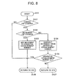
- FIG. 8 is a flowchart showing the judgment processing, according to the embodiment of the present invention, as whether or not the request for update is correct.
- the plug register managing unit 61 mainly executes the judgment processing.
- the judgment processing according to the embodiment of the present invention is to count the number of p2p connection established between the transmitting apparatus TR and the other apparatus, for each apparatus, which made the request for establishment of connection, and judge the correctness in accordance with variation of the number of connection established. Accordingly, the concept of the "number of established connection for each connected processing apparatus" for the transmitting apparatus TR is utilized, as the number of p2p connection established for each of the other apparatuses connected through the serial bus 64, in judgment of the correctness.
- Step S121 it is judged whether or not the request for update of the plug register includes change in the p2p counter 611 of the transmitting apparatus TR.
- Step S121 the request for update is judged to be correct, and the processing enters Step S13 as shown in FIG. 6. More specifically, when the request for update does not includes change in the p2p counter 611, no change therein leads to no relationship between the request for update and the p2p connection, with the result that such a request is judged as the request for update for the broadcast connection.
- the broadcast connection enables any other apparatus than the apparatus, which establishes the connection, to carry out the disconnection. Accordingly, it is judged that such a request is correct and satisfies the standard.
- Step S121 In case where it is judges in Step S121 that the request for update includes change in the p2p counter 611 (YES in Step S121), and namely that the request for update is a request of the p2p connection, on the other hand, it is then judged as whether or not the request for update includes increment in the p2p counter 611 (Step S122).
- Step S122 When it is judged that the request for update includes the increment in the p2p counter 611, and namely that such a request is a request for establishment of the p2p connection (YES in Step S122), an increment (e.g. of "1") due to the establishment is added to the number of established connection for each connected processing apparatus of the corresponding apparatus (Step S123) and then the processing enters Step S13 as shown in FIG. 7.
- Step S122 In case where it is judged in Step S122 that the request for update includes no increment in the p2p counter 611, and namely, the request for update is a request for disconnection of the p2p connection, (NO in Step S122), on the other hand, a decrement (e. g. of "1") due to the disconnection is subtracted from the number of established connection for each connected processing apparatus of the corresponding apparatus (Step S124).
- Step S125 After subtraction in Step S124, it is judged as whether or not the number of established connection for each connected processing apparatus is any one of "null" and a positive number (Step S125). At this stage, it is judged from the judgment in Step S125 that the request for update, in which the number of established connection for each connected processing apparatus is a negative number, is to disconnect the connection by any apparatus in which the p2p connection has not been established at that time. Accordingly, in the embodiment of the present invention, such a request for update is judged to be incorrect.
- Step S125 When the number of established connection for each connected processing apparatus is judged as any one of "null" and a positive number (YES in Step S125), the request for update is judged to be correct and then the processing enters Step S13 as shown in FIG. 7.
- Step S125 When the number of established connection for each connected processing apparatus is judged as a negative number (NO in Step S125) , it is judged that the request for update is not correct, and namely that such a request for update, which was made by the other apparatus than the apparatus having establishment of the p2p connection and does not satisfy the IEC-61883 Part 1 standard, and then the processing enters Step S15 as shown in FIG. 7.
- the number of established connection for each connected processing apparatus in the above-mentioned embodiment of the present invention may be stored for each of the apparatuses, which perform transfer and reception of information relative only to the apparatus and establish another connection to the other apparatus to perform transfer and reception of information relative thereto.
- Step S15 description will be given below of the protection processing of the p2p connection, which is to be performed in Step S15 when it is judged that the request for update does not satisfy the IEC-61883 Part 1 standard.
- a bus reset is generated to perform the protection processing.
- FIG. 9 is a view illustrating an initialization processing flow when the bus reset generates
- FIG. 10 is a view illustrating initialization of the judgment processing for correctness of the request for update, when the bus reset generates.
- Step S21 the judgment processing for correctness of the request for update itself is initialized. More specifically, the initialization processing is executed to set all of the number of established connection for each connected processing apparatus as "null" as shown in FIG. 10 (Step S211), in the embodiment of the present invention.
- Step S22 the plug register is initialized (Step S22), and then the processing enters Step S14 as shown in FIG. 7 (Step S23).
- Step S12 the above-described judgment processing (Step S12, etc.) is executed based on the initialization processing as shown in FIG. 9.
- Step S21 and Step S22 may be varied optionally. More specifically, the initialization of the judgment processing may be executed after completion of initialization of the oPCR 610. Alternatively, these processings may be executed simultaneously.
- the plug register (including oPCR 610) is initialized with the bus reset, without executing any update of the oPCR 610.
- the IEC-61883 Part 1 standard stipulates that a mode of connection, which has been established prior to the bus reset, is recovered within a second after generation of the bus reset.
- the transmitting state of the isochronous data is kept in the same state as that prior to the generation of the bus reset, within a second after the generation of the bus reset.
- the transmission of the isochronous data is not interrupted immediately before and after the generation of the bus reset. Accordingly, the generation of the bus reset makes it possible to protect the p2p connection to avoid any problem in transfer and receipt of the data.
- the request for update of the p2p connection which was made by the other apparatus connected through the serial bus 64, satisfies the predetermined standard, and when the standard is not satisfied, no response to the request for update is made, thus protecting the p2p connection from any request for update, which was made by any incorrect nonstandardized apparatus.
- the judgment according to the present invention is applicable to a case where, although the other apparatus connected to the serial bus 64 is based on the IEC-61883 Part 1 standard, a communication error may cause for some reasons. More specifically, there is a possibility that the p2p connection as already established may be interrupted in accordance with an erroneous request for update due to transmission error. In such a case, even when the transmitting apparatus TR received the erroneous request for update due to the transmission error, the plug register managing unit 61 judges that the request for update in which the number of established connection for each connected processing apparatus is a negative number, is to disconnect the connection by any apparatus in which the p2p connection has not actually been established at that time, with the result that no response to the request for update is made. It is therefore possible to avoid an erroneous update of the plug register due to the transmission error, thus protecting the p2p connection.
- the number of the p2p connection with the other apparatus is counted for each of the apparatus, and it is judged whether or not the request for update satisfies the standard, on the basis of the counted number. It is therefore possible to protect the p2p connections with all the apparatuses as connected, irrespective as whether that connection is established by the other apparatus or the transmitting apparatus.
- the bus reset When it is judged that any other apparatus by which the request for update of the plug register was made does not satisfy the IEC-61883 Part 1 standard, the bus reset generates, thus making it possible to protect the existing p2p connection to avoid any problem in transfer and receipt of the data.
- the above-mentioned processing ensures the protection of the existing p2p connection already established, without interruption thereof.
- Step S14 no processing is executed in Step S14, after the protection processing in Step S15 as shown in FIG. 7, leading to completion of the processing.
- the transmitting apparatus TR does not execute any update of the oPCR 610 in Step S15 as shown in FIG. 7, on the one hand, and a response packet in which the value of "arg_value" of the request packet received from the apparatus, by which the request for update was made, is changed to the value of "old_value", is sent in the result response processing in Step S14 .
- the apparatus which received such a response packet (i.e., the apparatus from which the request for update was sent) compares the "old_value" of the response packet as received with the "arg_value", which was sent by the own apparatus, to judge that the update has been successful, because these values are identical to each other. In this case, it is possible to protect the existing p2p connection, and reduce the possibility that the apparatus, which sent the incorrect request for update, makes a further incorrect and nonstandardized request for update to the transmitting apparatus TR, thus providing useful technical effects.
- Step S15 no update of the oPCR 610 is executed in Step S15 as shown in FIG. 7, and there may be performed, in the result response processing in Step S14, a processing of making either a response in which the value of "old_value” is changed to a different value from the actual register value, or a response having a response code of "resp_conflict_error", which is indicative of disablement in update of the data.
- the controller 60 is not essential in the embodiment of the present invention.
- the present invention is therefore applicable to an apparatus provided with no controller 60 for the transmitting apparatus, i.e., an apparatus, which provides no establishment of the p2p connection for itself, and has only a function of enabling establishment of the p2p connection upon a request from the other apparatus.
- the second embodiment is to protect the p2p connection, which was established by the transmitting apparatus for itself, against a request for disconnection of the p2p connection made by the other apparatus.
- FIG. 11 is a flowchart showing the judgment processing, according to the second embodiment of the present invention, as whether or not the request for update is correct
- FIG. 12 is a view illustrating initialization of the judgment processing for correctness of the request for update, when the bus reset generates in the second embodiment of the present invention.
- the plug register managing unit 61 serves as the reception device, the judgment device, the storage device, the the number of self-established connection calculating device and the protection device.
- the plug register managing unit 61 counts the number of the p2p connection established by the transmitting apparatus TR by itself, and make a judgment of correctness on the basis of variation of the number. Accordingly, the judgment utilizes the concept of the number of the p2p connection established by the transmitting apparatus TR by itself, i . e . , the number of self-established connection.
- Step S131 it is judged as whether or not the request for update of the plug register includes change in the p2p counter 611 of the transmitting apparatus TR (Step S131), as shown in FIG. 11.
- Step S131 the request for update is judged to be correct, and the processing enters Step S13 as shown in FIG. 7. More specifically, no change in the p2p counter 611 means that the request for update does not relate to the p2p connection, but relates to the broadcast connection. It is reasonable to judge that such a request for update is standardized and correct, because the broadcast connection enables any other apparatus than the apparatus, which established the connection, to carry out the disconnection.
- Step S132 it is then judged as whether the request for update was made by the controller 60 of the transmitting apparatus TR or by the other apparatus.
- Step S132 When it is judged that the request for update was made by the controller 60 of the transmitting apparatus TR (YES in Step S132), it is then judged as whether or not the request for update includes increment in the p2p counter 611 (Step S133).
- Step S133 In case where it is judged that the request for update includes increment in the p2p counter 611, and namely that such a request is a request for establishment of the p2p connection (YES in Step S133), an increment (e.g. of "1") due to the establishment is added to the the number of self-established connection (Step S134) and then the processing enters Step S13 as shown in FIG. 7.
- an increment e.g. of "1" due to the establishment is added to the the number of self-established connection (Step S134) and then the processing enters Step S13 as shown in FIG. 7.
- Step S133 In case where it is judged that the request for update includes no increment in the p2p counter 611, and namely that such a request is a request for disconnection of the p2p connection, made by the controller 60 (NO in Step S133), on the other hand, a decrement (e.g. of "1") due to the disconnection is subtracted from the the number of self-established connection (Step S135) and then the processing enters Step S13 as shown in FIG. 7.
- a decrement e.g. of "1”
- Step S132 in case where the request for update is made by the other apparatus (NO in Step S132), it is then judged whether or not such a request for update includes increment in the p2p counter 611 (Step S136).
- Step S136 In case where it is judged that the request for update includes increment in the p2p counter 611, and namely that the request for update is a request for establishment of the p2p connection made by the apparatus, which sent the request for update (YES in Step S136), it is then judged that such the request for update is correct, and the processing enters Step S13 as shown in FIG. 7.
- Step S137 it is then judged whether or not the value of the p2p counter 611 after the update is not less than the number of self-established connection.
- the p2p counter 611 indicates the total amount of the number of establishment. It is therefore reasonable to judge that the request for update in which the value of the p2p counter is less than the number of self-established connection, is an incorrect request for update made by any apparatus that does not satisfy the IEC-61883 Part 1 standard, because the value of the p2p counter 611 always become not less than the number of self-established connection.
- Step S137 In case where it is judged in Step S137 that the value of the p2p counter 611 after the update is not less than the number of self-established connection (YES in Step S137), the request for update is judged to be correct and then, the processing enters Step S13 as shown in FIG. 7.
- Step S137 In case where it is judged in Step S137 that the value of the p2p counter 611 after the update is less than the number of self-established connection (NO in Step S137) , it is then judged that the request for update is not correct, and namely, that such a request is a request for update, which was made by the other apparatus that does not satisfy the IEC-61883 Part 1 standard, than the apparatus having establishment of the p2p connection, and then the processing enters Step S15 as shown in FIG. 7.
- the protection processing after the judgment processing is executed in the same manner as the first embodiment of the present invention.
- a processing is executed to set the number of self-established connection as "null" in Step S21 upon generating the bus reset as shown in FIG. 12 (Step S221).
- the judgment of the embodiment of the present invention may be applicable to a case where, although the other apparatus connected to the serial bus 64 is based on the IEC-61883 Part 1 standard, a communication error may cause for some reasons.
- the plug register managing unit 61 judges that the request for update in which the value of the p2p counter is less than the number of self-established connection, is to disconnect the connection by any apparatus in which the p2p connection has not actually been established at that time, with the result that no response to the request for update is made. It is therefore possible to avoid an erroneous update of the plug register due to the transmission error, thus protecting the p2p connection.
- the number of the p2p connection, which was made by the own apparatus is counted, and the request for update in which the value of the p2p counter 611 is less than the above-mentioned number, is judged as a nonstandardized request, and the disconnection based on such a request is not executed. It is therefore possible to protect effectively the connection, which is established by the own apparatus, of the existing p2p connections as already established.
- the third embodiment is to protect the p2p connection, which was established in the transmitting apparatus TR by the other apparatus, against a request for disconnection of the p2p connection, which is to be transmitted.
- FIG. 13 is a flowchart showing the judgment processing, according to the third embodiment of the present invention, as whether or not the request for update is correct
- FIG. 14 is a flowchart illustrating initialization of the judgment processing for correctness of the request for update, when the bus reset generates in the third embodiment of the present invention.
- the plug register managing unit 61 serves as a reception device, a judgment device, a storage device, the number of externally established connection calculating device and a protection device.
- the judgment processing the number of the p2p connection to the transmitting apparatus, which is established by he other apparatus, is counted, and a judgment is made on the basis of variation of the number. Accordingly, the judgment utilizes the concept of the number of the p2p connection established by the other apparatus, which is connected to the IEEE serial bus 64, i.e., the number of externally established connection.
- Step S141 it is judged as whether or not the request for update of the plug register includes change in the p2p counter 611 of the transmitting apparatus TR.
- Step S141 the request for update is judged to be correct, and the processing enters Step S13 as shown in FIG. 7. More specifically, no change in the p2p counter 611 means that the request for update does not relate to the p2p connection, but relates to the broadcast connection. It is reasonable to judge that such a request for update is standardized and correct, because the broadcast connection enables any other apparatus than the apparatus, which established the connection, to carry out the disconnection.
- Step S142 it is then judged as whether or not the request for update was made by the controller 60 of the transmitting apparatus TR.
- Step S142 In case where it is judged that the request for update was made by the controller 60 of the transmitting apparatus TR (YES in Step S142), the request for update is judged to be correct, and the processing enters Step S13 as shown in FIG. 7.
- Step S143 it is then judged as whether or not the request for update includes increment in the p2p counter 611.
- Step S143 In case where it is judged that the request for update includes increment in the p2p counter 611, and namely that such a request is a request for establishment of the p2p connection made by the other apparatus (YES in Step S143), an increment (e.g. of "1") due to the establishment is added to the number of externally established connection (Step S144) and then the processing enters Step S13 as shown in FIG. 7.
- Step S143 In case where it is judged in Step S143 that the request for update includes no increment in the p2p counter 611, and namely that such a request is a request for disconnection of the p2p connection, made by the other apparatus (NO in Step S143) , on the other hand, a decrement (e.g. of "1") due to the disconnection is subtracted from the number of externally established connection (Step S145) , and it is then judged as whether or not the number of externally established connection after subtraction is anyone of "null" andapositive number (Step S146).
- a decrement e.g. of "1”
- the number of externally established connection which is the number of connection established by the other apparatus, of the p2p connections, may be assumes as "null". It is therefore judged that the request for update in which the number of externally established connection is a negative number is an incorrect request for update.
- Step S146 the request for update is judged to be correct, and the processing enters Step S13 as shown in FIG. 7.
- Step S146 In case where the number of externally established connection is judged to be negative (NO in Step S146), it is judged that the request for update is incorrect, and namely that such a request for update is a request, which was made by the other apparatus than the apparatus having establishment of the p2p connection and does not satisfy the IEC-61883 Part 1 standard, and then the processing enters Step S15 as shown in FIG. 7.
- the protection processing after the judgment processing is executed in the same manner as the first embodiment of the present invention.
- a processing is executed to set the other-apparatus-establishment number as "null" in Step S21 upon generating the bus reset as shown in FIG. 14 (Step S231) .
- the judgment of the embodiment of the present invention may be applicable to a case where, although the other apparatus connected to the serial bus 64 is based on the IEC-61883 Part 1 standard, a communication error may cause for some reasons.
- the plug register managing unit 61 judges that the request for update in which the other-apparatus-establishment number is negative, is to disconnect the connection by any apparatus in which the p2p connection has not actually been established at that time, with the result that no response to the request for update is made. It is therefore possible to avoid an erroneous update of the plug register due to the transmission error, thus protecting the p2p connection.
- the number of the p2p connection, which was made by the other apparatus is counted, and the request for update in which the value of the p2p counter 611 is negative, is judged as a nonstandardized request, and the disconnection of the p2p connection according to such a request is not executed. It is therefore possible to protect effectively the connection, which is established by the own apparatus, of the existing p2p connections as already established.
- the controller 60 is not essential in the embodiment of the present invention.
- the present invention is therefore applicable to an apparatus provided with no controller 60 for the transmitting apparatus, i.e., an apparatus, which provides no establishment of the p2p connection for itself, and has only a function of enabling establishment of the p2p connection upon a request from the other apparatus.
- the present invention is applied to the transmitting apparatus TR. It is needless to say that the present invention may be applicable to a receiving apparatus for receiving data in the similar manner.
- the receiving apparatus RE to which the present invention is applied includes a controller 70 and a plug register managing unit 71 in the same manner as the above-described transmitting apparatus TR.
- the receiving apparatus RE also includes a reception unit 72 for receiving an isochronous packet through the serial bus 74, and an information signal processing unit 73 for processing the isochronous packet as received in the form of information signals including audio information or video information.
- the plug register managing unit 71 which is logically provided with an iPCR 710, performs transfer and reception of control signals relative to the other apparatus through the controller 70 or the serial bus 74, and further updates the iPCR 710, and controls start and halt of reception by the reception unit 72.
- the receiving apparatus RE differs from the above-described transmitting apparatuses TR according to the first to third embodiments of the present invention only in that the p2p connection established by the oPCT 610 is protected in the transmitting apparatuses TR, while the p2p connection established by the iPCR 710 is protected in the receiving apparatus RE. Accordingly, the same judgment processing and the same protection of the p2p connection as those in the above-mentioned first to third embodiments of the present invention are applied in such a receiving apparatus RE.
- the present invention is applied to the transmitting apparatus, which is connected through the serial bus serving as an example of a network.
- the present invention may be applicable to a network to which the respective apparatuses are connected through a parallel bus or a radio communication.
- a program corresponding to the flowcharts of the update processing of the plug register and the judgment processing for correctness of the request for update, which are described above with reference to FIGS. 7 to 14, may be stored in an information recording medium such as a flexible disc. Execution of such a program by reading it through a microcomputer makes it possible to cause the microcomputer to function as the controller 60 or 70, and the plug register managing unit 61 or 71.
Landscapes
- Engineering & Computer Science (AREA)
- Computer Networks & Wireless Communication (AREA)
- Signal Processing (AREA)
- Information Transfer Systems (AREA)
- Communication Control (AREA)
- Small-Scale Networks (AREA)
Applications Claiming Priority (2)
| Application Number | Priority Date | Filing Date | Title |
|---|---|---|---|
| JP2003138915 | 2003-05-16 | ||
| JP2003138915A JP2004343526A (ja) | 2003-05-16 | 2003-05-16 | 通信装置、通信方法並びに通信用プログラム及び情報記録媒体 |
Publications (2)
| Publication Number | Publication Date |
|---|---|
| EP1487164A2 true EP1487164A2 (fr) | 2004-12-15 |
| EP1487164A3 EP1487164A3 (fr) | 2005-03-16 |
Family
ID=33296749
Family Applications (1)
| Application Number | Title | Priority Date | Filing Date |
|---|---|---|---|
| EP04252830A Withdrawn EP1487164A3 (fr) | 2003-05-16 | 2004-05-14 | Dispositif, methode, programme et medium d'enregistrement pour communications, o la legalite d'une requete de deconnexion est jugee |
Country Status (3)
| Country | Link |
|---|---|
| US (1) | US7420930B2 (fr) |
| EP (1) | EP1487164A3 (fr) |
| JP (1) | JP2004343526A (fr) |
Families Citing this family (3)
| Publication number | Priority date | Publication date | Assignee | Title |
|---|---|---|---|---|
| JP3952053B2 (ja) * | 2004-09-21 | 2007-08-01 | 船井電機株式会社 | 接続管理プログラム |
| US8166156B2 (en) * | 2006-11-30 | 2012-04-24 | Nokia Corporation | Failure differentiation and recovery in distributed systems |
| CN106465443B (zh) * | 2015-05-18 | 2020-01-17 | 华为技术有限公司 | D2d通信中的ip地址分配方法及用户设备 |
Citations (3)
| Publication number | Priority date | Publication date | Assignee | Title |
|---|---|---|---|---|
| EP1014364A1 (fr) * | 1998-12-25 | 2000-06-28 | Sony Corporation | Méthode de réception sur une chaíne d'appareils audiovisuels interconnectés |
| EP1073236A2 (fr) * | 1999-07-26 | 2001-01-31 | Samsung Electronics Co., Ltd. | Procédé de gestion des connexions d'une interface numérique |
| US20020171624A1 (en) * | 2001-05-03 | 2002-11-21 | Mitsubishi Digital Electronics America, Inc. | Control system and user interface for network of input devices |
Family Cites Families (8)
| Publication number | Priority date | Publication date | Assignee | Title |
|---|---|---|---|---|
| US5737600A (en) * | 1994-09-12 | 1998-04-07 | International Business Machines Corporation | Method and system for log management in a coupled data processing system |
| US6169725B1 (en) * | 1998-10-30 | 2001-01-02 | Sony Corporation Of Japan | Apparatus and method for restoration of internal connections in a home audio/video system |
| EP1071255A4 (fr) | 1999-01-22 | 2003-03-19 | Matsushita Electric Ind Co Ltd | Systeme de gestion de reseau, controleur, cible et consommateur destines a etre utilises dans ledit systeme de gestion de reseau |
| JP3454217B2 (ja) | 1999-12-28 | 2003-10-06 | 日本電気株式会社 | 通信経路制御方法、機器制御装置、及びブリッジ |
| US6388533B2 (en) * | 2000-03-02 | 2002-05-14 | Texas Instruments Incorporated | Programmable ring oscillator |
| JP4396011B2 (ja) | 2000-08-22 | 2010-01-13 | ソニー株式会社 | 情報制御方法、情報処理装置および情報制御システム |
| JP4166956B2 (ja) | 2001-01-12 | 2008-10-15 | パイオニア株式会社 | データ伝送システム、コネクション確立方法及び情報伝送装置 |
| US7392541B2 (en) * | 2001-05-17 | 2008-06-24 | Vir2Us, Inc. | Computer system architecture and method providing operating-system independent virus-, hacker-, and cyber-terror-immune processing environments |
-
2003
- 2003-05-16 JP JP2003138915A patent/JP2004343526A/ja active Pending
-
2004
- 2004-05-14 US US10/845,527 patent/US7420930B2/en not_active Expired - Fee Related
- 2004-05-14 EP EP04252830A patent/EP1487164A3/fr not_active Withdrawn
Patent Citations (3)
| Publication number | Priority date | Publication date | Assignee | Title |
|---|---|---|---|---|
| EP1014364A1 (fr) * | 1998-12-25 | 2000-06-28 | Sony Corporation | Méthode de réception sur une chaíne d'appareils audiovisuels interconnectés |
| EP1073236A2 (fr) * | 1999-07-26 | 2001-01-31 | Samsung Electronics Co., Ltd. | Procédé de gestion des connexions d'une interface numérique |
| US20020171624A1 (en) * | 2001-05-03 | 2002-11-21 | Mitsubishi Digital Electronics America, Inc. | Control system and user interface for network of input devices |
Also Published As
| Publication number | Publication date |
|---|---|
| US7420930B2 (en) | 2008-09-02 |
| EP1487164A3 (fr) | 2005-03-16 |
| JP2004343526A (ja) | 2004-12-02 |
| US20050025107A1 (en) | 2005-02-03 |
Similar Documents
| Publication | Publication Date | Title |
|---|---|---|
| US6275889B1 (en) | Connection control apparatus | |
| US6389496B1 (en) | Bridge including portals with ability to redefine network topology | |
| EP0827062A1 (fr) | Appareil électronique et son procédé de commande mode de fonctionnement | |
| EP1327328B1 (fr) | Procede permettant de connecter plusieurs bus de communication par des liaisons sans fil | |
| US6754184B2 (en) | Information processing apparatus and method, and distribution medium | |
| KR100746900B1 (ko) | 전자장치, 및 전자장치의 물리층 회로의 상태를 제어하는방법 | |
| US6895003B1 (en) | Communication system, apparatus, and method in which data transmission is interrupted for a bus reset | |
| JP3599048B2 (ja) | データ転送制御システム、電子機器、プログラム及びデータ転送制御方法 | |
| US6775714B1 (en) | Communication method, communication apparatus, communication system and providing medium | |
| EP1487164A2 (fr) | Dispositif, méthode, programme et médium d'enregistrement pour la communication où la légalité d'une requête de déconnexion est jugée | |
| JP3291926B2 (ja) | 電子機器制御方式 | |
| US6988200B2 (en) | Data transmit/receive device and data transmit/receive method | |
| JP4336536B2 (ja) | 伝送速度設定装置、伝送速度設定方法、情報伝送システム並びに伝送速度設定用プログラム及び情報記録媒体 | |
| US6457072B1 (en) | System and method for effectively performing physical direct memory access operations | |
| JP4166956B2 (ja) | データ伝送システム、コネクション確立方法及び情報伝送装置 | |
| US7227846B2 (en) | Data transmission/ reception system, connection restoring method and information transmission/ reception apparatus | |
| KR20040026137A (ko) | 인터페이스 회로 | |
| WO2020090361A1 (fr) | Dispositif de relais pour véhicule | |
| JP4683120B2 (ja) | 電子機器および通信方法 | |
| JP4546960B2 (ja) | 分散された複数の局のネットワークのためのネットワーク加入者局及び該ネットワーク加入者局を操作するための方法 | |
| JPWO2006090714A1 (ja) | 情報中継装置、情報中継方法及び情報中継用プログラム並びに情報記録媒体 | |
| EP1246402A1 (fr) | Procécédé pour connecter plusieurs bus de communication à l'aide d'une liaison sans fil | |
| EP1246400A1 (fr) | Procédé pour connecter plusieurs bus de communication à l'aide d'une liaison sans fil | |
| KR100677222B1 (ko) | Ieee 1394 기반의 양방향 비동기 연결 방법 | |
| JP2004241891A (ja) | 複数ノードがシリアルバスに接続されたシステムの通信方法 |
Legal Events
| Date | Code | Title | Description |
|---|---|---|---|
| PUAI | Public reference made under article 153(3) epc to a published international application that has entered the european phase |
Free format text: ORIGINAL CODE: 0009012 |
|
| AK | Designated contracting states |
Kind code of ref document: A2 Designated state(s): AT BE BG CH CY CZ DE DK EE ES FI FR GB GR HU IE IT LI LU MC NL PL PT RO SE SI SK TR |
|
| AX | Request for extension of the european patent |
Extension state: AL HR LT LV MK |
|
| PUAL | Search report despatched |
Free format text: ORIGINAL CODE: 0009013 |
|
| RTI1 | Title (correction) |
Free format text: COMMUNICATION APPARATUS, METHOD, PROGRAM AND RECORDING MEDIUM, WHERE THE LEGALITY OF A DISCONNECTION REQUEST IS JUDGED |
|
| AK | Designated contracting states |
Kind code of ref document: A3 Designated state(s): AT BE BG CH CY CZ DE DK EE ES FI FR GB GR HU IE IT LI LU MC NL PL PT RO SE SI SK TR |
|
| AX | Request for extension of the european patent |
Extension state: AL HR LT LV MK |
|
| 17P | Request for examination filed |
Effective date: 20050412 |
|
| AKX | Designation fees paid |
Designated state(s): DE FR GB |
|
| 17Q | First examination report despatched |
Effective date: 20050818 |
|
| 17Q | First examination report despatched |
Effective date: 20050818 |
|
| STAA | Information on the status of an ep patent application or granted ep patent |
Free format text: STATUS: THE APPLICATION IS DEEMED TO BE WITHDRAWN |
|
| 18D | Application deemed to be withdrawn |
Effective date: 20071005 |