EP1487053A1 - Antenna positioner with non-orthogonal axes and associated method - Google Patents
Antenna positioner with non-orthogonal axes and associated method Download PDFInfo
- Publication number
- EP1487053A1 EP1487053A1 EP04013483A EP04013483A EP1487053A1 EP 1487053 A1 EP1487053 A1 EP 1487053A1 EP 04013483 A EP04013483 A EP 04013483A EP 04013483 A EP04013483 A EP 04013483A EP 1487053 A1 EP1487053 A1 EP 1487053A1
- Authority
- EP
- European Patent Office
- Prior art keywords
- positioner
- level
- azimuthal
- cross
- canted
- Prior art date
- Legal status (The legal status is an assumption and is not a legal conclusion. Google has not performed a legal analysis and makes no representation as to the accuracy of the status listed.)
- Withdrawn
Links
Images


Classifications
-
- H—ELECTRICITY
- H01—ELECTRIC ELEMENTS
- H01Q—ANTENNAS, i.e. RADIO AERIALS
- H01Q3/00—Arrangements for changing or varying the orientation or the shape of the directional pattern of the waves radiated from an antenna or antenna system
- H01Q3/02—Arrangements for changing or varying the orientation or the shape of the directional pattern of the waves radiated from an antenna or antenna system using mechanical movement of antenna or antenna system as a whole
- H01Q3/08—Arrangements for changing or varying the orientation or the shape of the directional pattern of the waves radiated from an antenna or antenna system using mechanical movement of antenna or antenna system as a whole for varying two co-ordinates of the orientation
Definitions
- An antenna stabilization system is generally used when mounting an antenna on an object that is subject to pitch and roll motions, such as a ship at sea, a ground vehicle, an airplane, or a buoy, for example. It is desirable to maintain a line-of-sight between the antenna and a satellite, for example, to which it is pointed.
- the pointing direction of an antenna mounted on a ship at sea is subject to rotary movement of the ship caused by changes in the ship's heading, as well as to the pitch and roll motion caused by movement of the sea.
- U.S. Patent No. 4,156,241 to Mobley et al. discloses a satellite antenna mounted on a platform on a surface of a ship. The antenna is stabilized and decoupled from motion of the ship using sensors mounted on the platform.
- U.S. Patent No. 5,769,020 to Shields discloses a system for stabilizing platforms on board a ship. More specifically, the antenna is carried by a platform on the deck of the ship having a plurality of sensors thereon. The sensors on the platform cooperate with a plurality of sensors in a hull of the ship to sense localized motion due to pitch, roll, and variations from flexing of the ship to make corrections to the pointing direction of the antenna.
- U.S. Patent No. 4,596,989 to Smith et al. discloses an antenna system that includes an acceleration displaceable mass to compensate for linear acceleration forces caused by motion of a ship. The system senses motion of the ship and attempts to compensate for the motion by making adjustments to the position of the antenna.
- U.S. Patent No. 6,433,736 to Timothy, et al. discloses an antenna tracking system including an attitude and heading reference system that is mounted directly to an antenna or to a base upon which the antenna is mounted.
- the system also includes a controller connected to the attitude heading reference system. Internal navigation data is received from the attitude heading reference system.
- the system searches, and detects a satellite radio frequency beacon, and the controller initiates self scan tracking to point the antenna reflector in a direction of the satellite.
- An antenna stabilization system may include an azimuthal positioner, a cross-level positioner connected thereto, an elevational positioner connected to the cross-level positioner, and an antenna connected to the elevational positioner.
- the system may also include respective motors to move the azimuthal, cross-level, and elevational positioner so that a line-of-sight between the antenna and a satellite is maintained.
- a tachometer feedback configuration including a base-mounted inertial reference sensor (BMIRS), has been used to reduce the coupling between positioners.
- This configuration may increase pointing errors due to misalignments, phasing, scaling and structural deflections between the BMIRS and the positioners.
- an antenna assembly for operation on a moving platform and wherein a controller decouples at least two positioners.
- the antenna assembly may comprise a base to be mounted on the moving platform, an azimuthal positioner extending upwardly from the base, and a canted cross-level positioner extending from the azimuthal positioner at a cross-level cant angle canted from perpendicular.
- the canted cross-level positioner may be rotatable about a cross-level axis to define a roll angle, resulting in coupling between the azimuthal positioner and the canted cross-level positioner.
- An elevational positioner may be connected to the canted cross-level positioner. Again, coupling will result between the elevational positioner and the azimuthal positioner because of the roll angle.
- the antenna assembly may also comprise an antenna, such as a reflector antenna, connected to the elevational positioner.
- a controller may operate the azimuthal, canted cross-level, and elevational positioners to aim the antenna along a desired line-of-sight.
- the controller may also decouple at least one of the azimuthal and canted cross-level positioners, and the azimuthal and elevational positioners. Decoupling the positioners advantageously allows for more accurate pointing of the antenna assembly along the desired line-of-sight and without requiring excessive corrective motion of the positioners.
- the elevational positioner may comprise an azimuthal gyroscope associated therewith, and the canted cross-level positioner may comprise a cross-level motor and cross-level tachometer associated therewith. Accordingly, the controller may decouple based upon the azimuthal gyroscope and the cross-level tachometer. More specifically, the controller may decouple based upon the roll angle and an elevation angle defined by the desired line-of-sight being within respective first predetermined ranges.
- the elevational positioner may also comprise a cross-level gyroscope associated therewith, and the azimuthal positioner may comprise an azimuthal motor and an azimuthal tachometer associated therewith. Accordingly, the controller may decouple based upon the cross-level gyroscope and the azimuthal tachometer. More specifically, the controller may decouple based upon the roll angle and an elevation angle defined by the desired line-of-sight being within respective second predetermined ranges.
- Each of the azimuthal, canted cross-level, and elevational positioners may comprise respective motors and tachometers associated therewith, and the controller may decouple based upon the tachometers. More specifically, the controller may decouple based upon the roll angle and an elevation angle defined by the desired line-of-sight being within third predetermined ranges.
- the elevational positioner may comprise an azimuthal gyroscope, a cross-level gyroscope, and an elevational gyroscope associated therewith. Accordingly, the controller may advantageously decouple the positioners of the antenna assembly based upon at least some of the gyroscopes and tachometers.
- the present invention is directed to an antenna positioning assembly comprising at least a first and second positioner non-orthogonally connected together thereby coupling the first and second positioners to one another.
- the antenna positioning assembly may also comprise a controller for operating the positioners to aim an antenna along a desired line-of-sight while decoupling the at least first and second positioners.
- a method aspect of the present invention is for operating an antenna assembly comprising a plurality of positioners.
- the plurality of positioners may comprise at least first and second positioners non-orthogonally connected together thereby coupling the first and second positioners to one another.
- the method may comprise controlling the positioners to aim an antenna connected thereto along a desired line-of-sight and while decoupling the at least first and second positioners.
- the antenna assembly 20 illustratively includes a base 22 mounted to a moving platform 24 .
- the moving platform 24 may, for example, be a deck of a ship at sea, a buoy, a land vehicle traveling across terrain, or any other moving platform as understood by those skilled in the art.
- the antenna assembly 20 illustratively includes an azimuthal positioner 30 extending upwardly from the base 22 .
- the azimuthal positioner 30 has an azimuthal axis 32 about which the azimuthal positioner may rotate.
- a canted cross-level positioner 34 illustratively extends from the azimuthal positioner 30 at a cross-level cant angle ⁇ canted from perpendicular.
- the canted cross-level positioner 34 has a cross-level axis 36 about which the canted cross-level positioner may rotate and is generally referred to by those skilled in the art as roll.
- the angel defined by the roll of the canted cross-level positioner 34 defines a roll angle x resulting in coupling between the canted cross-level positioner and the azimuthal positioner, as illustrated by the arrow 16 in FIG. 2.
- the cross-level cant angle ⁇ may be between a range of about 30 to 60 degrees from perpendicular.
- the amount of coupling between the azimuthal positioner 30 and the canted cross-level positioner 32 is affected by the roll angle x .
- An elevational positioner 38 is illustratively connected to the canted cross-level positioner 34 . This also results in coupling between the elevational positioner 38 and the azimuthal positioner 30 because of the roll angle x , as illustrated by the arrow 17 in FIG. 2. The amount of coupling between the elevational positioner 38 and the azimuthal positioner 30 is affected by the roll angle x , as well as the cross-level cant angle ⁇ .
- the elevational positioner 38 includes an elevational axis 39 about which the elevational positioner may rotate. The rotation of the elevational positioner 38 about the elevational axis 39 allows the antenna assembly 20 to make elevational adjustments.
- the antenna assembly illustratively includes an azimuthal gyroscope 60 , a cross-level gyroscope 62 , and an elevational gyroscope 64 . More particularly, the azimuthal gyroscope 60 , the cross-level gyroscope 62 , and the elevational gyroscope 64 are mounted on the elevational positioner 38 . The elevational gyroscope 64 is in line with the elevation angle of the line-of-sight of the elevational positioner 38 as caused by movement thereof.
- the azimuthal gyroscope 60 is in line with the azimuthal angle of the line-of-sight of the elevational positioner as caused by movement of the azimuthal positioner 30 and the cross-level positioner 34 .
- the cross-level gyroscope 62 is in line with roll angle of the line-of-sight of the elevational positioner 38 as caused by movement of the canted cross-level positioner 34 and the azimuthal positioner 30 .
- each of the azimuthal positioner 30 , the canted cross-level positioner 34 , and the elevational positioner 38 illustratively comprises a motor 33 , 35, 37 and a tachometer 70, 72, 74 associated therewith.
- An antenna 40 is illustratively connected to the elevational positioner 38 .
- the antenna 40 may be a reflector antenna, for example, suitable for receiving signals from a satellite, or any other type of antenna as understood by those skilled in the art.
- Rotation about the azimuthal axis 32 , the cross-level axis 34 , and the elevational axis 39 advantageously allows the antenna 40 to be pointed in any direction to provide accurate line-of-sight aiming between the antenna and the satellite, for example. This may be especially advantageous in cases where the antenna is mounted on a rotating platform.
- Torques for the azimuthal positioner 30 , the canted cross-level positioner 34 , and the elevational positioner 38 may be calculated from the equations shown, for clarity of explanation, in the block diagram 80 of FIG. 3. More specifically, these derivations provide line-of-sight kinematics 85, which, as will be described in greater detail below, are used in subsequent derivations.
- ⁇ is the fixed elevational cant
- x is the roll angle
- ⁇ is the azimuthal angle
- ⁇ is the elevational angle.
- T X mtr -T EL/XL x I X x ⁇ X x
- the torques on the canted cross-level positioner 34 are as follows:
- Kinematic torques from the canted cross-level positioner 34 may operate through the inverse transform on the azimuthal positioner 30 .
- reaction torques from the elevational positioner 38 to the canted cross-level positioner 34 operated through the canted roll angle x and the cross-level cant angle ⁇ are produced:
- the sum of the two vectors' x-terms is equal to the torque of the cross-level motor 35 as calculated above.
- the y-term in the second vector is equal to the cross-level motor torque.
- the effective inertia seen by the elevational motor 37 is also illustrated.
- the sum of torques on the azimuthal axis 32 are as follows:
- the block diagram 80 illustrated in FIG. 3 is produced showing the relationship between the torques of the azimuthal motor 33 and the cross-level motor 35 , and the line-of-sight inertial and relative rates 84 , and the developed line-of-sight kinematics 85 .
- the antenna assembly 20 further includes a controller 50 for operating the azimuthal positioner 30 , canted cross-level positioner 34 , and the elevational positioner 38 to aim the antenna 40 along a desired line-of-sight.
- the controller 50 also decouples the azimuthal positioner 30 and canted cross-level positioner 34 , and/or the azimuthal positioner and the elevational positioner 38 . Decoupling the positioners 30, 34, 38, advantageously decreases undesired motion of one of the positioners due to desired motion of another one of the positioners. In other words, the motion and the torques of the positioners are no longer coupled.
- the controller 50 decouples using a low elevation line-of-sight stabilization control algorithm 90 , shown for clarity of explanation in the block diagram 95 of FIG. 4.
- the controller 50 decouples based upon the azimuthal gyroscope 60 and the cross-level tachometer 72 . More particularly, the controller 50 decouples based upon the cross-level cant angle ⁇ and an elevation angle ⁇ defined by the desired line-of-sight being within predetermined ranges.
- the line-of-sight elevation angle relative to the base may between about -30 and +70 degrees.
- the block diagram 95 of FIG. 4 shows the low elevation line-of-sight stabilization control algorithm 90 for controlling the antenna assembly 20 . Derivation of the low elevation line-of-sight stabilization control algorithm 90 is now described.
- the azimuthal positioner 30 couples to the canted cross-level positioner 34 .
- a 1 is the transition matrix
- x represents the states
- u represents the motor torques
- B relates the motor torques to the state rates such that:
- a matrix, k is inserted before the motor torques, as follows:
- the k ij matrix is substituted to produce the following:
- the above matrix is desirable for the above matrix to be the identity matrix that will decouple the canted cross-level positioner 34 and the elevational positioner 38 from the azimuthal positioner 30 , and visa-versa:
- the controller 50 must switch before ⁇ reaches 60 degrees, having the canted cross-level positioner 34 control the line-of-sight azimuthal rate and the azimuthal positioner 30 controlled in a relative rate or tach mode.
- the controller 50 decouples using a high elevation line-of-sight stabilization control illustrated for clarity of explanation in the block diagram 96 of FIG. 5.
- the line-of-sight kinematics 87 is also illustrated in the block diagram 96 of FIG. 5.
- the controller 50 decouples based upon the cross-level gyroscope 62 and the azimuthal tachometer 70 . More particularly, the controller 50 decouples based upon the roll angle ⁇ and an elevation angle ⁇ defined by the desired line-of-sight being within predetermined ranges. For example, for a cant of 30 degrees the line-of-sight elevation angle relative to the base may between about +50 and +120 degrees.
- FIG. 5 A block diagram showing a high elevation line-of-sight stabilization control algorithm 91 for controlling the antenna assembly 20 is illustrated in FIG. 5. Derivation of the high elevation line-of-sight stabilization control algorithm 91 is now described.
- the canted cross-level positioner 34 may be used to stabilize an azimuthal line of sight, and the azimuthal positioner 30 may be controlled in a relative rate mode. There may be a hysteresis or phasing region so that the switching between the positioners used to stabilize the line-of-sight does not occur rapidly.
- the measurement equation changes from the low elevation case (described above) to the following:
- the controller 50 decouples using a tachometer feedback control algorithm 92 (FIG. 6).
- the controller 50 decouples based on the tachometers 70, 72, 74 .
- the controller 50 decouples without regard to the elevation angle
- a block diagram 97 showing a tachometer feedback control algorithm 92 for controlling the antenna assembly 20 is illustrated, for clarity of explanation, in FIG. 6.
- the line-of-sight kinematics 80 is illustrated in the block diagram 97 of FIG. 7. Derivation of the tachometer feedback control algorithm 92 is now described.
- Inertial information of motion of the base 22 is provided to stabilize the line-of-sight.
- the tachometer feedback control algorithm 92 developed below addresses decoupling between the positioners 30, 34, 38 without regard to elevation angles. Those skilled in the art will recognize that the dynamics do not change from the equations derived above, but the kinematics do. For demonstrative purposes only, inertia tensors of each of the positioners 30, 34, 38 are shown below:
- the resulting control architecture is shown in the block diagram 97 FIG. 6.
- FIG. 7a is a graph of a low elevation, azimuthal line-of-sight step response modeled in accordance with the prior art, and showing an azimuthal gyroscope reading 100 , a cross-level tachometer reading 101 , and an elevational gyroscope reading 102 .
- FIG. 7b is a graph of a low elevation, azimuthal line-of-sight step response modeled in accordance with the present invention, and showing the results of decoupling.
- the resulting gyroscope reading 100' cross-level tachometer reading 101' , and elevational gyroscope reading 102' are shown.
- the oscillations of the canted cross-level positioner 34 have illustratively been removed, and the azimuthal positioner 30 illustratively settles to its desired rate.
- FIG. 8a is a graph of a low elevation cross-level tachometer step response modeled in accordance with the prior art showing an azimuthal gyroscope reading 105 , a cross-level tachometer reading 106, and an elevational gyroscope reading 107 .
- FIG. 8b is a graph of a low elevation, cross-level tachometer step response modeled in accordance with the present invention, and showing the results of decoupling. More particularly, the resulting azimuthal gyroscope reading 105' , cross-level tachometer reading 106' , and elevational gyroscope reading 107' are shown.
- the oscillations of the azimuthal positioner 30 have illustratively been removed, and the canted cross-level positioner 34 more quickly settles to its desired rate.
- FIG. 9a is a graph of a low elevation, elevational line-of-sight step response modeled in accordance with the prior art, and showing an azimuthal gyroscope reading 110 , a cross-level tachometer reading 111 , and an elevational gyroscope reading 112 .
- FIG. 9b is a graph of a low elevation, elevational line-of-sight step response modeled in accordance with the present invention, and showing the results of decoupling. More particularly, the resulting azimuthal gyroscope reading 110' , cross-level tachometer reading 111' , and elevational gyroscope reading 112' are shown. The oscillations of the elevational positioner 38 have illustratively been removed.
- FIG. 10a is a graph of a high elevation, azimuthal line-of-sight step response modeled in accordance with the prior art, and showing an azimuthal tachometer reading 113 , a cross-level gyroscope reading 114 , and an elevational gyroscope reading 115 .
- FIG. 10b is a graph of a high elevation, azimuthal line-of-sight step response modeled in accordance with the present invention, and showing the results of decoupling. More particularly, the resulting azimuthal tachometer reading 113' , cross-level gyroscope reading 114' , and elevational gyroscope reading 115' are shown.
- the oscillations of the azimuthal positioner 30 have illustratively been removed, and the canted cross-level positioner 34 more quickly settles to its desired rate.
- FIG. 11a is a graph of a high elevation azimuthal line-of-sight step response modeled in accordance with the prior art, and showing an azimuthal tachometer reading 118 , an azimuthal gyroscope reading 117 , and an elevational gyroscope reading 119.
- FIG. 11b is a graph of a high elevation, azimuthal line-of-sight step response modeled in accordance with the present invention, and showing the results of decoupling. More particularly, the resulting azimuthal tachometer reading 118' , azimuthal gyroscope reading 117' , and elevational gyroscope reading 119' are shown. The oscillations of the azimuthal positioner 30 have illustratively been removed.
- FIG. 12a is a graph of a high elevation, elevational line-of-sight step response modeled in accordance with the prior art, and showing an azimuthal tachometer reading 121 , an azimuthal gyroscope reading 120 , and an elevational gyroscope reading 122 .
- FIG. 12b is a graph of a high elevation, elevational line-of-sight step response, modeled in accordance with the present invention, and showing the results of decoupling. More particularly, the resulting azimuthal tachometer reading 121' , azimuthal gyroscope reading 120' , and elevational gyroscope reading 122' are shown. The oscillations of the azimuthal positioner 30 have illustratively been removed.
- FIG. 13a is a graph of an azimuthal step response modeled in accordance with the prior art, and showing an azimuthal tachometer reading 124 , a cross-level tachometer reading 126 , and an elevational tachometer reading 128 .
- FIG. 13b is a graph of an azimuthal step response modeled in accordance with the present invention, and showing the results of decoupling. More particularly, the resulting azimuthal tachometer reading 124' , cross-level tachometer reading 126' , and elevational tachometer reading 128' are shown. The oscillations of the canted cross-level positioner 34 and the elevational positioner 38 have been removed.
- FIG. 14a is a graph of a cross-level step response modeled in accordance with the prior art, and showing an azimuthal tachometer reading 130 , a cross-level tachometer reading 132 , and an elevational tachometer reading 134 .
- FIG. 14b is a graph of a cross-level step response modeled in accordance with the present invention, and showing the results of decoupling. More particularly, the resulting azimuthal tachometer reading 130', cross-level tachometer reading 132', and elevational tachometer reading 134' are shown. The oscillations of the azimuthal positioner 30 and the elevational positioner 38 have illustratively been removed.
- FIG. 15a is a graph of an elevational step response modeled in accordance with the prior art, and showing an azimuthal tachometer reading 136 , a cross-level tachometer reading 137, and an elevational tachometer reading 138 .
- FIG. 15b is a graph of an elevational step response modeled in accordance with the present invention, and showing the results of decoupling. More particularly, the resulting azimuthal tachometer reading 136' , cross-level tachometer reading 137' , and elevational tachometer reading 138' are shown. Oscillations of the azimuthal positioner 30 and the canted cross-level positioner 34 have illustratively been removed.
- a method aspect of the present invention is for operating an antenna assembly 20 comprising a plurality of positioners and a controller 50 .
- the plurality of positioners comprises at least first and second positioners non-orthogonally connected together, thereby coupling the first and second positioners to one another.
- the method comprises controlling the positioners to aim an antenna 40 connected thereto along a desired line-of-sight and while decoupling the at least first and second positioners.
Abstract
Description
- An antenna stabilization system is generally used when mounting an antenna on an object that is subject to pitch and roll motions, such as a ship at sea, a ground vehicle, an airplane, or a buoy, for example. It is desirable to maintain a line-of-sight between the antenna and a satellite, for example, to which it is pointed. The pointing direction of an antenna mounted on a ship at sea, for example, is subject to rotary movement of the ship caused by changes in the ship's heading, as well as to the pitch and roll motion caused by movement of the sea.
- U.S. Patent No. 4,156,241 to Mobley et al. discloses a satellite antenna mounted on a platform on a surface of a ship. The antenna is stabilized and decoupled from motion of the ship using sensors mounted on the platform. U.S. Patent No. 5,769,020 to Shields discloses a system for stabilizing platforms on board a ship. More specifically, the antenna is carried by a platform on the deck of the ship having a plurality of sensors thereon. The sensors on the platform cooperate with a plurality of sensors in a hull of the ship to sense localized motion due to pitch, roll, and variations from flexing of the ship to make corrections to the pointing direction of the antenna.
- U.S. Patent No. 4,596,989 to Smith et al. discloses an antenna system that includes an acceleration displaceable mass to compensate for linear acceleration forces caused by motion of a ship. The system senses motion of the ship and attempts to compensate for the motion by making adjustments to the position of the antenna.
- U.S. Patent No. 6,433,736 to Timothy, et al. discloses an antenna tracking system including an attitude and heading reference system that is mounted directly to an antenna or to a base upon which the antenna is mounted. The system also includes a controller connected to the attitude heading reference system. Internal navigation data is received from the attitude heading reference system. The system searches, and detects a satellite radio frequency beacon, and the controller initiates self scan tracking to point the antenna reflector in a direction of the satellite.
- An antenna stabilization system may include an azimuthal positioner, a cross-level positioner connected thereto, an elevational positioner connected to the cross-level positioner, and an antenna connected to the elevational positioner. The system may also include respective motors to move the azimuthal, cross-level, and elevational positioner so that a line-of-sight between the antenna and a satellite is maintained.
- It has been found, however, that movement of one of the positioners may cause undesired movement of another positioner, i.e., the azimuthal positioner may be coupled to the cross-level positioner, or the elevational positioner. Accordingly, larger, more powerful motors have been used to compensate for the undesired motion. It has also been found, however, that the use of larger motors may cause overcompensation, and an accumulation of undesired movement, which may increase errors in the pointing direction.
- A tachometer feedback configuration, including a base-mounted inertial reference sensor (BMIRS), has been used to reduce the coupling between positioners. This configuration, however, may increase pointing errors due to misalignments, phasing, scaling and structural deflections between the BMIRS and the positioners.
- In view of the foregoing background, it is therefore an object of the present invention to provide an antenna assembly for accurately and reliably pointing an antenna along a desired line-of-sight.
- This and other objects, features, and advantages in accordance with the present invention are provided by an antenna assembly for operation on a moving platform and wherein a controller decouples at least two positioners. More particularly, the antenna assembly may comprise a base to be mounted on the moving platform, an azimuthal positioner extending upwardly from the base, and a canted cross-level positioner extending from the azimuthal positioner at a cross-level cant angle canted from perpendicular. The canted cross-level positioner may be rotatable about a cross-level axis to define a roll angle, resulting in coupling between the azimuthal positioner and the canted cross-level positioner. An elevational positioner may be connected to the canted cross-level positioner. Again, coupling will result between the elevational positioner and the azimuthal positioner because of the roll angle.
- The antenna assembly may also comprise an antenna, such as a reflector antenna, connected to the elevational positioner. A controller may operate the azimuthal, canted cross-level, and elevational positioners to aim the antenna along a desired line-of-sight. Moreover, the controller may also decouple at least one of the azimuthal and canted cross-level positioners, and the azimuthal and elevational positioners. Decoupling the positioners advantageously allows for more accurate pointing of the antenna assembly along the desired line-of-sight and without requiring excessive corrective motion of the positioners.
- The elevational positioner may comprise an azimuthal gyroscope associated therewith, and the canted cross-level positioner may comprise a cross-level motor and cross-level tachometer associated therewith. Accordingly, the controller may decouple based upon the azimuthal gyroscope and the cross-level tachometer. More specifically, the controller may decouple based upon the roll angle and an elevation angle defined by the desired line-of-sight being within respective first predetermined ranges.
- The elevational positioner may also comprise a cross-level gyroscope associated therewith, and the azimuthal positioner may comprise an azimuthal motor and an azimuthal tachometer associated therewith. Accordingly, the controller may decouple based upon the cross-level gyroscope and the azimuthal tachometer. More specifically, the controller may decouple based upon the roll angle and an elevation angle defined by the desired line-of-sight being within respective second predetermined ranges.
- Each of the azimuthal, canted cross-level, and elevational positioners may comprise respective motors and tachometers associated therewith, and the controller may decouple based upon the tachometers. More specifically, the controller may decouple based upon the roll angle and an elevation angle defined by the desired line-of-sight being within third predetermined ranges.
- The elevational positioner may comprise an azimuthal gyroscope, a cross-level gyroscope, and an elevational gyroscope associated therewith. Accordingly, the controller may advantageously decouple the positioners of the antenna assembly based upon at least some of the gyroscopes and tachometers.
- Considered in somewhat different terms, the present invention is directed to an antenna positioning assembly comprising at least a first and second positioner non-orthogonally connected together thereby coupling the first and second positioners to one another. The antenna positioning assembly may also comprise a controller for operating the positioners to aim an antenna along a desired line-of-sight while decoupling the at least first and second positioners.
- A method aspect of the present invention is for operating an antenna assembly comprising a plurality of positioners. The plurality of positioners may comprise at least first and second positioners non-orthogonally connected together thereby coupling the first and second positioners to one another. The method may comprise controlling the positioners to aim an antenna connected thereto along a desired line-of-sight and while decoupling the at least first and second positioners.
-
- FIG. 1 is a schematic diagram of an antenna assembly according to the present invention.
- FIG. 2 is a more detailed schematic block diagram of the antenna assembly shown in FIG. 1.
- FIG. 3 is a schematic block diagram illustrating coupling between an azimuthal and canted cross-level positioner of the antenna assembly shown in FIG. 1.
- FIG. 4 is a schematic block diagram illustrating a low elevation line-of-sight stabilization control algorithm for controlling the antenna assembly shown in FIG. 1.
- FIG. 5 is a schematic block diagram illustrating a high elevation line-of-sight stabilization control algorithm for controlling the antenna assembly shown in FIG. 1.
- FIG. 6 is a schematic block diagram illustrating a tachometer feedback control algorithm for controlling the antenna assembly shown in FIG. 1.
- FIG. 7a is a graph of operation of an antenna assembly modeled in accordance with the prior art.
- FIG. 7b is a graph of operation of an antenna assembly modeled in accordance with the present invention.
- FIG. 8a is a graph of operation of an antenna assembly modeled in accordance with the prior art.
- FIG. 8b is a graph of operation of an antenna assembly modeled in accordance with the present invention.
- FIG. 9a is a graph of operation of an antenna assembly modeled in accordance with the prior art.
- FIG. 9b is a graph of operation of an antenna assembly modeled in accordance with the present invention.
- FIG. 10a is a graph of operation of an antenna assembly modeled in accordance with the prior art.
- FIG. 10b is a graph of operation of an antenna assembly modeled in accordance with the present invention.
- FIG. 11a is a graph of operation of an antenna assembly modeled in accordance with the prior art.
- FIG. 11b is a graph of operation of an antenna assembly modeled in accordance with the present invention.
- FIG. 12a is a graph of operation of an antenna assembly modeled in accordance with the prior art.
- FIG. 12b is a graph of operation of an antenna assembly modeled in accordance with the present invention.
- FIG. 13a is a graph of operation of an antenna assembly modeled in accordance with the prior art.
- FIG. 13b is a graph of operation of an antenna assembly modeled in accordance with the present invention.
- FIG. 14a is a graph of operation of an antenna assembly modeled in accordance with the prior art.
- FIG. 14b is a graph of operation of an antenna assembly modeled in accordance with the present invention.
- FIG. 15a is a graph of operation of an antenna assembly modeled in accordance with the prior art.
- FIG. 15b is a graph of operation of an antenna assembly modeled in accordance with the present invention.
-
- The present invention will now be described more fully hereinafter with reference to the accompanying drawings, in which preferred embodiments of the invention are shown. This invention may, however, be embodied in many different forms and should not be construed as limited to the embodiments set forth herein. Rather, these embodiments are provided so that this disclosure will be thorough and complete, and will fully convey the scope of the invention to those skilled in the art. Like numbers refer to like elements throughout, and prime notations are used in the graphs to refer to modeled readings resulting after decoupling.
- Referring initially to FIGS. 1-2, an antenna assembly 20 for operation on a moving platform 24 is now described. The antenna assembly 20 illustratively includes a base 22 mounted to a moving platform 24. The moving platform 24 may, for example, be a deck of a ship at sea, a buoy, a land vehicle traveling across terrain, or any other moving platform as understood by those skilled in the art.
- The antenna assembly 20 illustratively includes an azimuthal positioner 30 extending upwardly from the base 22. The azimuthal positioner 30 has an azimuthal axis 32 about which the azimuthal positioner may rotate.
- A canted cross-level positioner 34 illustratively extends from the azimuthal positioner 30 at a cross-level cant angle γ canted from perpendicular. The canted cross-level positioner 34 has a cross-level axis 36 about which the canted cross-level positioner may rotate and is generally referred to by those skilled in the art as roll. The angel defined by the roll of the canted cross-level positioner 34 defines a roll angle x resulting in coupling between the canted cross-level positioner and the azimuthal positioner, as illustrated by the arrow 16 in FIG. 2. As will be discussed in greater detail below, the cross-level cant angle γ may be between a range of about 30 to 60 degrees from perpendicular. The amount of coupling between the azimuthal positioner 30 and the canted cross-level positioner 32 is affected by the roll angle x.
- An elevational positioner 38 is illustratively connected to the canted cross-level positioner 34. This also results in coupling between the elevational positioner 38 and the azimuthal positioner 30 because of the roll angle x, as illustrated by the arrow 17 in FIG. 2. The amount of coupling between the elevational positioner 38 and the azimuthal positioner 30 is affected by the roll angle x, as well as the cross-level cant angle γ. The elevational positioner 38 includes an elevational axis 39 about which the elevational positioner may rotate. The rotation of the elevational positioner 38 about the elevational axis 39 allows the antenna assembly 20 to make elevational adjustments.
- The antenna assembly illustratively includes an azimuthal gyroscope 60, a cross-level gyroscope 62, and an elevational gyroscope 64. More particularly, the azimuthal gyroscope 60, the cross-level gyroscope 62, and the elevational gyroscope 64 are mounted on the elevational positioner 38. The elevational gyroscope 64 is in line with the elevation angle of the line-of-sight of the elevational positioner 38 as caused by movement thereof. The azimuthal gyroscope 60 is in line with the azimuthal angle of the line-of-sight of the elevational positioner as caused by movement of the azimuthal positioner 30 and the cross-level positioner 34. The cross-level gyroscope 62 is in line with roll angle of the line-of-sight of the elevational positioner 38 as caused by movement of the canted cross-level positioner 34 and the azimuthal positioner 30. Further, each of the azimuthal positioner 30, the canted cross-level positioner 34, and the elevational positioner 38 illustratively comprises a motor 33, 35, 37 and a tachometer 70, 72, 74 associated therewith.
- An antenna 40 is illustratively connected to the elevational positioner 38. The antenna 40 may be a reflector antenna, for example, suitable for receiving signals from a satellite, or any other type of antenna as understood by those skilled in the art. Rotation about the azimuthal axis 32, the cross-level axis 34, and the elevational axis 39 advantageously allows the antenna 40 to be pointed in any direction to provide accurate line-of-sight aiming between the antenna and the satellite, for example. This may be especially advantageous in cases where the antenna is mounted on a rotating platform.
- Line of sight kinematics are developed below to provide a better understanding of the interaction between the azimuthal 30, the canted cross-level 34, and the elevational positioners 38:

- These kinematics assume a stationary base, accordingly:
- In these equations, the superscript E represents the elevational positioner, x represents cross-level positioner, and A represents azimuthal positioner.
- The cross-level positioner inertial rates are extracted from the following:
- The above equations provide a relative rate as measured by the cross-level positioner tachometer 72 using the following equations:

- The above equations provide the elevational positioner 38 relative rate as measured by the elevational tachometer 74 using the following equation:


- Torques for the azimuthal positioner 30, the canted cross-level positioner 34, and the elevational positioner 38, may be calculated from the equations shown, for clarity of explanation, in the block diagram 80 of FIG. 3. More specifically, these derivations provide line-of-sight kinematics 85, which, as will be described in greater detail below, are used in subsequent derivations. In the following equations, γ is the fixed elevational cant, x is the roll angle, ψ is the azimuthal angle, and is the elevational angle.
- The torques on each of the elevational 38, canted cross-level 34, and azimuthal 30 positioners are now developed. The torque on the elevational positioner is developed from the following equations:

- The second term above is much smaller than the first term and, accordingly, is set to zero. The off diagonal terms in the inertia tensor are typically small and are considered zero for this analysis. Substituting for the elevational positioner 38 accelerations from the kinematics above produces the following equation:

- The elevational torques that act on the cross-level positioner 34 through the inverse transform to produce the following:

- The torques about a cross-level axis 36 are determined as follows:

- Collecting the ω ˙ X / x terms, the effective inertia 81 seen by the cross-level motor 35 is as follows:
- The sum of torques on the cross-level axis 36 is as follows:

- The torques on the canted cross-level positioner 34 are as follows:

- Kinematic torques from the canted cross-level positioner 34 may operate through the inverse transform on the azimuthal positioner 30. In addition the reaction torques from the elevational positioner 38 to the canted cross-level positioner 34 operated through the canted roll angle x and the cross-level cant angle γ. Accordingly, the following equations are produced:


- The sum of the two vectors' x-terms is equal to the torque of the cross-level motor 35 as calculated above. The y-term in the second vector is equal to the cross-level motor torque.
- The resulting z-term, as it acts on azimuthal axis 32, is as follows:

- For azimuthal motion, the torques about the azimuthal axis 32 (ΣF=ma) are as follows:
- Collecting the ω ˙ A / z terms, the effective inertia seen by the azimuthal motor 32 is:

- The effective inertia seen by the elevational motor 37 is also illustrated. The sum of torques on the azimuthal axis 32 are as follows:

- Accordingly, and for clarity of explanation, the block diagram 80 illustrated in FIG. 3 is produced showing the relationship between the torques of the azimuthal motor 33 and the cross-level motor 35, and the line-of-sight inertial and relative rates 84, and the developed line-of-sight kinematics 85.
- The antenna assembly 20 further includes a controller 50 for operating the azimuthal positioner 30, canted cross-level positioner 34, and the elevational positioner 38 to aim the antenna 40 along a desired line-of-sight. The controller 50 also decouples the azimuthal positioner 30 and canted cross-level positioner 34, and/or the azimuthal positioner and the elevational positioner 38. Decoupling the positioners 30, 34, 38, advantageously decreases undesired motion of one of the positioners due to desired motion of another one of the positioners. In other words, the motion and the torques of the positioners are no longer coupled.
- In one embodiment the controller 50 decouples using a low elevation line-of-sight stabilization control algorithm 90, shown for clarity of explanation in the block diagram 95 of FIG. 4. The controller 50 decouples based upon the azimuthal gyroscope 60 and the cross-level tachometer 72. More particularly, the controller 50 decouples based upon the cross-level cant angle γ and an elevation angle defined by the desired line-of-sight being within predetermined ranges. For example, the line-of-sight elevation angle relative to the base may between about -30 and +70 degrees.
- The block diagram 95 of FIG. 4 shows the low elevation line-of-sight stabilization control algorithm 90 for controlling the antenna assembly 20. Derivation of the low elevation line-of-sight stabilization control algorithm 90 is now described.
- As noted above, when the azimuthal motor 33 torques, the azimuthal positioner 30 couples to the canted cross-level positioner 34. The line-of-sight kinematics 86 is illustrated in the block diagram 95 of FIG. 4. Derivation of the low elevation line-of-sight algorithm 90 begins with the following state equation:
- In the above equation, A1 is the transition matrix, x represents the states, u represents the motor torques, and B relates the motor torques to the state rates such that:

- In the above equation,

- The angular accelerations are meant to be in the first term and are later placed on the left hand side of the equation for state consistency. Also, the variables, 'J' and 'I', are interchangeable as the mass moment of inertia. A measurement equation is as follows:
- In the above equation, y is the measurement state, C relates the states to the measurements, and D relates the motor torques to the measurements:

- A matrix, k, is inserted before the motor torques, as follows:

- Rewriting the state equation produces the following equation:

- The above state equation is now substituted into the measurement equation as follows:

- The above equation may be simplified for easier manipulation as follows:

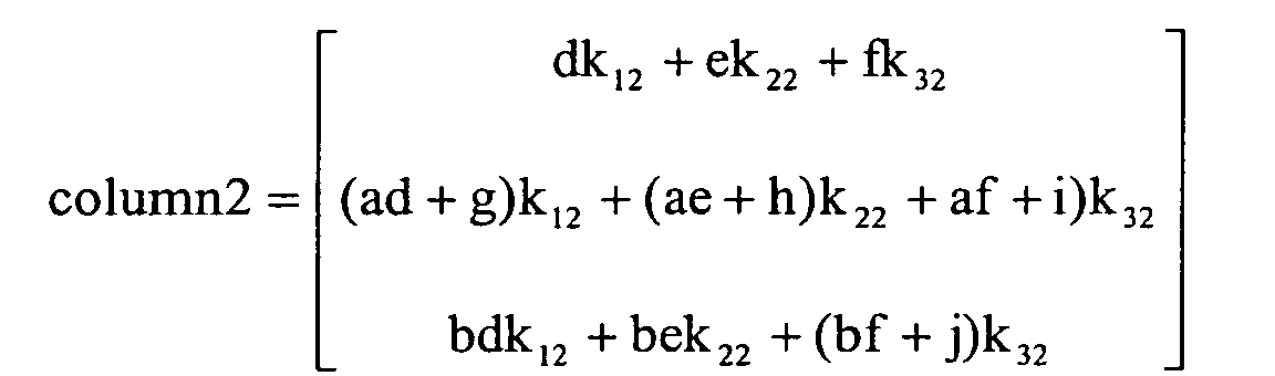
- The kij matrix is substituted to produce the following:

- The above is reduced as follows:


- It is desirable for the above matrix to be the identity matrix that will decouple the canted cross-level positioner 34 and the elevational positioner 38 from the azimuthal positioner 30, and visa-versa:

- This forms the following three equations:


- Solving for kij produces the following:
- In the above equation,

- For a fixed cant angle γ of approximately 30 degrees, it is noted that the denominator goes to zero for a non-solution when χ is zero and the elevational angle is 60 degrees. Therefore, a singularity exists. To keep this from happening the controller 50 must switch before reaches 60 degrees, having the canted cross-level positioner 34 control the line-of-sight azimuthal rate and the azimuthal positioner 30 controlled in a relative rate or tach mode.
- Accordingly, an operator may compensate as though the axes were orthogonal. The resulting control architecture is illustrated by the block diagram 95 of FIG. 4.
- In another embodiment of the antenna assembly 20, the controller 50 decouples using a high elevation line-of-sight stabilization control illustrated for clarity of explanation in the block diagram 96 of FIG. 5. The line-of-sight kinematics 87 is also illustrated in the block diagram 96 of FIG. 5. The controller 50 decouples based upon the cross-level gyroscope 62 and the azimuthal tachometer 70. More particularly, the controller 50 decouples based upon the roll angle γ and an elevation angle defined by the desired line-of-sight being within predetermined ranges. For example, for a cant of 30 degrees the line-of-sight elevation angle relative to the base may between about +50 and +120 degrees.
- A block diagram showing a high elevation line-of-sight stabilization control algorithm 91 for controlling the antenna assembly 20 is illustrated in FIG. 5. Derivation of the high elevation line-of-sight stabilization control algorithm 91 is now described.
- At high elevation angles, the canted cross-level positioner 34 may be used to stabilize an azimuthal line of sight, and the azimuthal positioner 30 may be controlled in a relative rate mode. There may be a hysteresis or phasing region so that the switching between the positioners used to stabilize the line-of-sight does not occur rapidly. The measurement equation changes from the low elevation case (described above) to the following:

- The dynamics (state equations) are the same and substituting into the measurement equation produces the following:

- Simplifying the above for easier manipulation produces the following:

- Inserting the kij matrix produces the following:

- The above equation reduces to the following:


- This forms the following three equations:


- Solving for kij produces the following:
- In the above equations,

- It should be noted that the denominator goes to zero for a non-solution when the elevation angle is 0 degrees. Therefore, a singularity exists. To keep this from happening the control must switch before the elevation angle reaches 0 degrees. The resulting control architecture is illustrated in Figure 5.
- In yet another embodiment of the antenna positioner 20, the controller 50 decouples using a tachometer feedback control algorithm 92 (FIG. 6). The controller 50 decouples based on the tachometers 70, 72, 74. For this embodiment the controller 50 decouples without regard to the elevation angle
- A block diagram 97 showing a tachometer feedback control algorithm 92 for controlling the antenna assembly 20 is illustrated, for clarity of explanation, in FIG. 6. The line-of-sight kinematics 80 is illustrated in the block diagram 97 of FIG. 7. Derivation of the tachometer feedback control algorithm 92 is now described.
- Inertial information of motion of the base 22 is provided to stabilize the line-of-sight. The tachometer feedback control algorithm 92 developed below addresses decoupling between the positioners 30, 34, 38 without regard to elevation angles. Those skilled in the art will recognize that the dynamics do not change from the equations derived above, but the kinematics do. For demonstrative purposes only, inertia tensors of each of the positioners 30, 34, 38 are shown below:


- Bracketed numbers represent the motor axis. Using the kinematics developed above, the measurement equation becomes:

- The dynamics are the same and, accordingly, are substituted into the measurement equation to produce the following:

- Simplifying the above equation for easier manipulation produces the following:

- Inserting the kij matrix into the above equation produces the following:which may then be reduced to:


- Setting the three column matrix above to the identity matrix forms the following three equations:


- Solving for kij produces the following:
- In the above equation,

- The resulting control architecture is shown in the block diagram 97 FIG. 6.
- Turning now additionally to the graphs of FIGS. 7a - 15b, modeled results of decoupling of the antenna assembly 20 is now described. FIG. 7a is a graph of a low elevation, azimuthal line-of-sight step response modeled in accordance with the prior art, and showing an azimuthal gyroscope reading 100, a cross-level tachometer reading 101, and an elevational gyroscope reading 102. FIG. 7b is a graph of a low elevation, azimuthal line-of-sight step response modeled in accordance with the present invention, and showing the results of decoupling. More particularly, the resulting gyroscope reading 100', cross-level tachometer reading 101', and elevational gyroscope reading 102' are shown. The oscillations of the canted cross-level positioner 34 have illustratively been removed, and the azimuthal positioner 30 illustratively settles to its desired rate.
- FIG. 8a is a graph of a low elevation cross-level tachometer step response modeled in accordance with the prior art showing an azimuthal gyroscope reading 105, a cross-level tachometer reading 106, and an elevational gyroscope reading 107. FIG. 8b is a graph of a low elevation, cross-level tachometer step response modeled in accordance with the present invention, and showing the results of decoupling. More particularly, the resulting azimuthal gyroscope reading 105', cross-level tachometer reading 106', and elevational gyroscope reading 107' are shown. The oscillations of the azimuthal positioner 30 have illustratively been removed, and the canted cross-level positioner 34 more quickly settles to its desired rate.
- FIG. 9a is a graph of a low elevation, elevational line-of-sight step response modeled in accordance with the prior art, and showing an azimuthal gyroscope reading 110, a cross-level tachometer reading 111, and an elevational gyroscope reading 112. FIG. 9b is a graph of a low elevation, elevational line-of-sight step response modeled in accordance with the present invention, and showing the results of decoupling. More particularly, the resulting azimuthal gyroscope reading 110', cross-level tachometer reading 111', and elevational gyroscope reading 112' are shown. The oscillations of the elevational positioner 38 have illustratively been removed.
- FIG. 10a is a graph of a high elevation, azimuthal line-of-sight step response modeled in accordance with the prior art, and showing an azimuthal tachometer reading 113, a cross-level gyroscope reading 114, and an elevational gyroscope reading 115. FIG. 10b is a graph of a high elevation, azimuthal line-of-sight step response modeled in accordance with the present invention, and showing the results of decoupling. More particularly, the resulting azimuthal tachometer reading 113', cross-level gyroscope reading 114', and elevational gyroscope reading 115' are shown. The oscillations of the azimuthal positioner 30 have illustratively been removed, and the canted cross-level positioner 34 more quickly settles to its desired rate.
- FIG. 11a is a graph of a high elevation azimuthal line-of-sight step response modeled in accordance with the prior art, and showing an azimuthal tachometer reading 118, an azimuthal gyroscope reading 117, and an elevational gyroscope reading 119. FIG. 11b is a graph of a high elevation, azimuthal line-of-sight step response modeled in accordance with the present invention, and showing the results of decoupling. More particularly, the resulting azimuthal tachometer reading 118', azimuthal gyroscope reading 117', and elevational gyroscope reading 119' are shown. The oscillations of the azimuthal positioner 30 have illustratively been removed.
- FIG. 12a is a graph of a high elevation, elevational line-of-sight step response modeled in accordance with the prior art, and showing an azimuthal tachometer reading 121, an azimuthal gyroscope reading 120, and an elevational gyroscope reading 122. FIG. 12b is a graph of a high elevation, elevational line-of-sight step response, modeled in accordance with the present invention, and showing the results of decoupling. More particularly, the resulting azimuthal tachometer reading 121', azimuthal gyroscope reading 120', and elevational gyroscope reading 122' are shown. The oscillations of the azimuthal positioner 30 have illustratively been removed.
- FIG. 13a is a graph of an azimuthal step response modeled in accordance with the prior art, and showing an azimuthal tachometer reading 124, a cross-level tachometer reading 126, and an elevational tachometer reading 128. FIG. 13b is a graph of an azimuthal step response modeled in accordance with the present invention, and showing the results of decoupling. More particularly, the resulting azimuthal tachometer reading 124', cross-level tachometer reading 126', and elevational tachometer reading 128' are shown. The oscillations of the canted cross-level positioner 34 and the elevational positioner 38 have been removed.
- FIG. 14a is a graph of a cross-level step response modeled in accordance with the prior art, and showing an azimuthal tachometer reading 130, a cross-level tachometer reading 132, and an elevational tachometer reading 134. FIG. 14b is a graph of a cross-level step response modeled in accordance with the present invention, and showing the results of decoupling. More particularly, the resulting azimuthal tachometer reading 130', cross-level tachometer reading 132', and elevational tachometer reading 134' are shown. The oscillations of the azimuthal positioner 30 and the elevational positioner 38 have illustratively been removed.
- FIG. 15a is a graph of an elevational step response modeled in accordance with the prior art, and showing an azimuthal tachometer reading 136, a cross-level tachometer reading 137, and an elevational tachometer reading 138. FIG. 15b is a graph of an elevational step response modeled in accordance with the present invention, and showing the results of decoupling. More particularly, the resulting azimuthal tachometer reading 136', cross-level tachometer reading 137', and elevational tachometer reading 138' are shown. Oscillations of the azimuthal positioner 30 and the canted cross-level positioner 34 have illustratively been removed.
- A method aspect of the present invention is for operating an antenna assembly 20 comprising a plurality of positioners and a controller 50. The plurality of positioners comprises at least first and second positioners non-orthogonally connected together, thereby coupling the first and second positioners to one another. The method comprises controlling the positioners to aim an antenna 40 connected thereto along a desired line-of-sight and while decoupling the at least first and second positioners.
Claims (10)
- An antenna positioning assembly for operation on a moving platform comprising:a plurality of positioners comprising at least first and second positioners non-orthogonally connected together thereby coupling said first and second positioners to one another; anda controller for operating said positioners to aim an antenna along a desired line-of-sight and while decoupling the at least first and second positioners.
- An antenna positioning assembly according to Claim 1 wherein said first positioner comprises an azimuthal positioner; wherein said second positioner comprises a canted cross-level positioner extending from said azimuthal positioner resulting in coupling therebetween; further comprising an azimuthal gyroscope; wherein said canted cross-level positioner comprises a cross-level motor and cross-level tachometer associated therewith; and wherein said controller decouples based upon said azimuthal gyroscope and said cross-level tachometer.
- An antenna positioning assembly according to Claim 1 wherein said first positioner comprises an azimuthal positioner; wherein said second positioner comprises a canted cross-level positioner extending from said azimuthal positioner resulting in coupling therebetween; further comprising a cross-level gyroscope; wherein said azimuthal positioner comprises an azimuthal motor and an azimuthal tachometer associated therewith; and wherein said controller decouples based upon said cross-level gyroscope and said azimuthal tachometer.
- An antenna positioning assembly according to Claim 1 wherein said first positioner comprises an azimuthal positioner; wherein said second positioner comprises a canted cross-level positioner extending from said azimuthal positioner at a cross-level cant angle canted from perpendicular and rotatable about a cross-level axis to define a roll angle resulting in coupling therebetween; wherein said plurality of positioners further comprises an elevational positioner connected to said canted cross-level positioner resulting in coupling between said elevational positioner and said azimuthal positioner because of said roll angle; wherein each of said azimuthal, canted cross-level, and elevational positioners comprises respective motors and tachometers associated therewith; and wherein said controller decouples based upon said tachometers.
- An antenna positioning assembly according to Claim 1 wherein said first positioner comprises an azimuthal positioner; wherein said second positioner comprises a canted cross-level positioner extending from said azimuthal positioner at a cross-level cant angle canted from perpendicular and rotatable about a cross-level axis to define a roll angle resulting in coupling therebetween; wherein said plurality of positioners further comprises an elevational positioner connected to said canted cross-level positioner resulting in coupling between said elevational positioner and said azimuthal positioner because of said roll angle.
- A method for operating an antenna assembly comprising a plurality of positioners, the plurality of positioners comprising at least first and second positioners non-orthogonally connected together thereby coupling the first and second positioners to one another, the method comprising:controlling the positioners to aim an antenna connected thereto along a desired line-of-sight and while decoupling the at least first and second positioners.
- A method according to Claim 6 wherein the first positioner comprises an azimuthal positioner; wherein the second positioner comprises a canted cross-level positioner extending from the azimuthal positioner at a cross-level cant angle canted from perpendicular and rotatable about a cross-level axis to define a roll angle resulting in coupling therebetween; wherein the antenna assembly comprises an azimuthal gyroscope; wherein the canted cross-level positioner comprises a cross-level motor and cross-level tachometer associated therewith; and wherein controlling is based upon the azimuthal gyroscope and the cross-level tachometer.
- A method according to Claim 6 wherein the first positioner comprises an azimuthal positioner; wherein the second positioner comprises a canted cross-level positioner extending from the azimuthal positioner at a cross-level cant angle canted from perpendicular and rotatable about a cross-level axis to define a roll angle resulting in coupling therebetween; wherein the antenna assembly comprises a cross-level gyroscope; wherein the azimuthal positioner comprises an azimuthal motor and an azimuthal tachometer associated therewith; and wherein controlling is based upon the cross-level gyroscope and the azimuthal tachometer.
- A method according to Claim 6 wherein the first positioner comprises an azimuthal positioner; wherein the second positioner comprises a canted cross-level positioner extending from the azimuthal positioner at a cross-level cant angle canted from perpendicular and rotatable about a cross-level axis to define a roll angle resulting in coupling therebetween; wherein the plurality of positioners further comprises an elevational positioner connected to the canted cross-level positioner resulting in coupling between the elevational positioner and the azimuthal positioner because of the roll angle; wherein each of the azimuthal, canted cross-level, and elevational positioners comprises respective motors and tachometers associated therewith; and wherein controlling is based upon the tachometers.
- A method according to Claim 6 wherein the first positioner comprises an azimuthal positioner; wherein the second positioner comprises a canted cross level positioner extending from the azimuthal positioner at a cross-level cant angle canted from perpendicular and rotatable about a cross-level axis to define a roll angle resulting in coupling therebetween; wherein the plurality of positioners further comprises an elevational positioner connected to the canted cross-level positioner.
Applications Claiming Priority (2)
| Application Number | Priority Date | Filing Date | Title |
|---|---|---|---|
| US458851 | 2003-06-11 | ||
| US10/458,851 US6859185B2 (en) | 2003-06-11 | 2003-06-11 | Antenna assembly decoupling positioners and associated methods |
Publications (1)
| Publication Number | Publication Date |
|---|---|
| EP1487053A1 true EP1487053A1 (en) | 2004-12-15 |
Family
ID=33299653
Family Applications (1)
| Application Number | Title | Priority Date | Filing Date |
|---|---|---|---|
| EP04013483A Withdrawn EP1487053A1 (en) | 2003-06-11 | 2004-06-08 | Antenna positioner with non-orthogonal axes and associated method |
Country Status (2)
| Country | Link |
|---|---|
| US (1) | US6859185B2 (en) |
| EP (1) | EP1487053A1 (en) |
Families Citing this family (169)
| Publication number | Priority date | Publication date | Assignee | Title |
|---|---|---|---|---|
| US20040208499A1 (en) * | 2002-09-07 | 2004-10-21 | Grober David E. | Stabilized buoy platform for cameras, sensors, illuminators and tools |
| FI121517B (en) * | 2004-02-11 | 2010-12-15 | Tracker Oy | Directional Antenna Mechanism |
| US7541766B1 (en) * | 2004-06-01 | 2009-06-02 | Sato Jeffrey S | System and method for the intelligent use of software deadband control in a control system |
| WO2006050392A1 (en) * | 2004-10-28 | 2006-05-11 | Seaspace Corporation | Antenna positioner system |
| US8061226B2 (en) * | 2008-06-02 | 2011-11-22 | Kvh Industries, Inc. | System and method for closed loop gyroscope stabilization |
| DE112009003183T5 (en) * | 2008-12-17 | 2012-02-16 | Asc Signal Corporation | Method, device and system for tracking a subreflector of a reflector antenna |
| US10009065B2 (en) | 2012-12-05 | 2018-06-26 | At&T Intellectual Property I, L.P. | Backhaul link for distributed antenna system |
| US9113347B2 (en) | 2012-12-05 | 2015-08-18 | At&T Intellectual Property I, Lp | Backhaul link for distributed antenna system |
| US9999038B2 (en) | 2013-05-31 | 2018-06-12 | At&T Intellectual Property I, L.P. | Remote distributed antenna system |
| US9525524B2 (en) | 2013-05-31 | 2016-12-20 | At&T Intellectual Property I, L.P. | Remote distributed antenna system |
| US9391692B2 (en) * | 2013-07-05 | 2016-07-12 | Gilat Satellite Networks Ltd. | System for dual frequency range mobile two-way satellite communications |
| US8897697B1 (en) | 2013-11-06 | 2014-11-25 | At&T Intellectual Property I, Lp | Millimeter-wave surface-wave communications |
| US9209902B2 (en) | 2013-12-10 | 2015-12-08 | At&T Intellectual Property I, L.P. | Quasi-optical coupler |
| US9692101B2 (en) | 2014-08-26 | 2017-06-27 | At&T Intellectual Property I, L.P. | Guided wave couplers for coupling electromagnetic waves between a waveguide surface and a surface of a wire |
| US9768833B2 (en) | 2014-09-15 | 2017-09-19 | At&T Intellectual Property I, L.P. | Method and apparatus for sensing a condition in a transmission medium of electromagnetic waves |
| US10063280B2 (en) | 2014-09-17 | 2018-08-28 | At&T Intellectual Property I, L.P. | Monitoring and mitigating conditions in a communication network |
| US9628854B2 (en) | 2014-09-29 | 2017-04-18 | At&T Intellectual Property I, L.P. | Method and apparatus for distributing content in a communication network |
| US9615269B2 (en) | 2014-10-02 | 2017-04-04 | At&T Intellectual Property I, L.P. | Method and apparatus that provides fault tolerance in a communication network |
| US9685992B2 (en) | 2014-10-03 | 2017-06-20 | At&T Intellectual Property I, L.P. | Circuit panel network and methods thereof |
| US9503189B2 (en) | 2014-10-10 | 2016-11-22 | At&T Intellectual Property I, L.P. | Method and apparatus for arranging communication sessions in a communication system |
| US9973299B2 (en) | 2014-10-14 | 2018-05-15 | At&T Intellectual Property I, L.P. | Method and apparatus for adjusting a mode of communication in a communication network |
| US9762289B2 (en) | 2014-10-14 | 2017-09-12 | At&T Intellectual Property I, L.P. | Method and apparatus for transmitting or receiving signals in a transportation system |
| US9627768B2 (en) | 2014-10-21 | 2017-04-18 | At&T Intellectual Property I, L.P. | Guided-wave transmission device with non-fundamental mode propagation and methods for use therewith |
| US9577306B2 (en) | 2014-10-21 | 2017-02-21 | At&T Intellectual Property I, L.P. | Guided-wave transmission device and methods for use therewith |
| US9520945B2 (en) | 2014-10-21 | 2016-12-13 | At&T Intellectual Property I, L.P. | Apparatus for providing communication services and methods thereof |
| US9564947B2 (en) | 2014-10-21 | 2017-02-07 | At&T Intellectual Property I, L.P. | Guided-wave transmission device with diversity and methods for use therewith |
| US9653770B2 (en) | 2014-10-21 | 2017-05-16 | At&T Intellectual Property I, L.P. | Guided wave coupler, coupling module and methods for use therewith |
| US9780834B2 (en) | 2014-10-21 | 2017-10-03 | At&T Intellectual Property I, L.P. | Method and apparatus for transmitting electromagnetic waves |
| US9312919B1 (en) | 2014-10-21 | 2016-04-12 | At&T Intellectual Property I, Lp | Transmission device with impairment compensation and methods for use therewith |
| US9769020B2 (en) | 2014-10-21 | 2017-09-19 | At&T Intellectual Property I, L.P. | Method and apparatus for responding to events affecting communications in a communication network |
| US9800327B2 (en) | 2014-11-20 | 2017-10-24 | At&T Intellectual Property I, L.P. | Apparatus for controlling operations of a communication device and methods thereof |
| US9680670B2 (en) | 2014-11-20 | 2017-06-13 | At&T Intellectual Property I, L.P. | Transmission device with channel equalization and control and methods for use therewith |
| US9544006B2 (en) | 2014-11-20 | 2017-01-10 | At&T Intellectual Property I, L.P. | Transmission device with mode division multiplexing and methods for use therewith |
| US10243784B2 (en) | 2014-11-20 | 2019-03-26 | At&T Intellectual Property I, L.P. | System for generating topology information and methods thereof |
| US9654173B2 (en) | 2014-11-20 | 2017-05-16 | At&T Intellectual Property I, L.P. | Apparatus for powering a communication device and methods thereof |
| US10340573B2 (en) | 2016-10-26 | 2019-07-02 | At&T Intellectual Property I, L.P. | Launcher with cylindrical coupling device and methods for use therewith |
| US9461706B1 (en) | 2015-07-31 | 2016-10-04 | At&T Intellectual Property I, Lp | Method and apparatus for exchanging communication signals |
| US9997819B2 (en) | 2015-06-09 | 2018-06-12 | At&T Intellectual Property I, L.P. | Transmission medium and method for facilitating propagation of electromagnetic waves via a core |
| US9954287B2 (en) | 2014-11-20 | 2018-04-24 | At&T Intellectual Property I, L.P. | Apparatus for converting wireless signals and electromagnetic waves and methods thereof |
| US9742462B2 (en) | 2014-12-04 | 2017-08-22 | At&T Intellectual Property I, L.P. | Transmission medium and communication interfaces and methods for use therewith |
| US10009067B2 (en) | 2014-12-04 | 2018-06-26 | At&T Intellectual Property I, L.P. | Method and apparatus for configuring a communication interface |
| US10144036B2 (en) | 2015-01-30 | 2018-12-04 | At&T Intellectual Property I, L.P. | Method and apparatus for mitigating interference affecting a propagation of electromagnetic waves guided by a transmission medium |
| US9876570B2 (en) | 2015-02-20 | 2018-01-23 | At&T Intellectual Property I, Lp | Guided-wave transmission device with non-fundamental mode propagation and methods for use therewith |
| US9749013B2 (en) | 2015-03-17 | 2017-08-29 | At&T Intellectual Property I, L.P. | Method and apparatus for reducing attenuation of electromagnetic waves guided by a transmission medium |
| US9705561B2 (en) | 2015-04-24 | 2017-07-11 | At&T Intellectual Property I, L.P. | Directional coupling device and methods for use therewith |
| US10224981B2 (en) | 2015-04-24 | 2019-03-05 | At&T Intellectual Property I, Lp | Passive electrical coupling device and methods for use therewith |
| US9793954B2 (en) | 2015-04-28 | 2017-10-17 | At&T Intellectual Property I, L.P. | Magnetic coupling device and methods for use therewith |
| US9948354B2 (en) | 2015-04-28 | 2018-04-17 | At&T Intellectual Property I, L.P. | Magnetic coupling device with reflective plate and methods for use therewith |
| US9490869B1 (en) | 2015-05-14 | 2016-11-08 | At&T Intellectual Property I, L.P. | Transmission medium having multiple cores and methods for use therewith |
| US9871282B2 (en) | 2015-05-14 | 2018-01-16 | At&T Intellectual Property I, L.P. | At least one transmission medium having a dielectric surface that is covered at least in part by a second dielectric |
| US9748626B2 (en) | 2015-05-14 | 2017-08-29 | At&T Intellectual Property I, L.P. | Plurality of cables having different cross-sectional shapes which are bundled together to form a transmission medium |
| US10679767B2 (en) | 2015-05-15 | 2020-06-09 | At&T Intellectual Property I, L.P. | Transmission medium having a conductive material and methods for use therewith |
| US10650940B2 (en) | 2015-05-15 | 2020-05-12 | At&T Intellectual Property I, L.P. | Transmission medium having a conductive material and methods for use therewith |
| US9917341B2 (en) | 2015-05-27 | 2018-03-13 | At&T Intellectual Property I, L.P. | Apparatus and method for launching electromagnetic waves and for modifying radial dimensions of the propagating electromagnetic waves |
| US10154493B2 (en) | 2015-06-03 | 2018-12-11 | At&T Intellectual Property I, L.P. | Network termination and methods for use therewith |
| US10103801B2 (en) | 2015-06-03 | 2018-10-16 | At&T Intellectual Property I, L.P. | Host node device and methods for use therewith |
| US10812174B2 (en) | 2015-06-03 | 2020-10-20 | At&T Intellectual Property I, L.P. | Client node device and methods for use therewith |
| US10348391B2 (en) | 2015-06-03 | 2019-07-09 | At&T Intellectual Property I, L.P. | Client node device with frequency conversion and methods for use therewith |
| US9866309B2 (en) | 2015-06-03 | 2018-01-09 | At&T Intellectual Property I, Lp | Host node device and methods for use therewith |
| US9912381B2 (en) | 2015-06-03 | 2018-03-06 | At&T Intellectual Property I, Lp | Network termination and methods for use therewith |
| US9913139B2 (en) | 2015-06-09 | 2018-03-06 | At&T Intellectual Property I, L.P. | Signal fingerprinting for authentication of communicating devices |
| US9608692B2 (en) | 2015-06-11 | 2017-03-28 | At&T Intellectual Property I, L.P. | Repeater and methods for use therewith |
| US10142086B2 (en) | 2015-06-11 | 2018-11-27 | At&T Intellectual Property I, L.P. | Repeater and methods for use therewith |
| US9820146B2 (en) | 2015-06-12 | 2017-11-14 | At&T Intellectual Property I, L.P. | Method and apparatus for authentication and identity management of communicating devices |
| US9667317B2 (en) | 2015-06-15 | 2017-05-30 | At&T Intellectual Property I, L.P. | Method and apparatus for providing security using network traffic adjustments |
| US9865911B2 (en) | 2015-06-25 | 2018-01-09 | At&T Intellectual Property I, L.P. | Waveguide system for slot radiating first electromagnetic waves that are combined into a non-fundamental wave mode second electromagnetic wave on a transmission medium |
| US9509415B1 (en) | 2015-06-25 | 2016-11-29 | At&T Intellectual Property I, L.P. | Methods and apparatus for inducing a fundamental wave mode on a transmission medium |
| US9640850B2 (en) | 2015-06-25 | 2017-05-02 | At&T Intellectual Property I, L.P. | Methods and apparatus for inducing a non-fundamental wave mode on a transmission medium |
| US10341142B2 (en) | 2015-07-14 | 2019-07-02 | At&T Intellectual Property I, L.P. | Apparatus and methods for generating non-interfering electromagnetic waves on an uninsulated conductor |
| US9628116B2 (en) | 2015-07-14 | 2017-04-18 | At&T Intellectual Property I, L.P. | Apparatus and methods for transmitting wireless signals |
| US9836957B2 (en) | 2015-07-14 | 2017-12-05 | At&T Intellectual Property I, L.P. | Method and apparatus for communicating with premises equipment |
| US9722318B2 (en) | 2015-07-14 | 2017-08-01 | At&T Intellectual Property I, L.P. | Method and apparatus for coupling an antenna to a device |
| US10170840B2 (en) | 2015-07-14 | 2019-01-01 | At&T Intellectual Property I, L.P. | Apparatus and methods for sending or receiving electromagnetic signals |
| US9847566B2 (en) | 2015-07-14 | 2017-12-19 | At&T Intellectual Property I, L.P. | Method and apparatus for adjusting a field of a signal to mitigate interference |
| US10320586B2 (en) | 2015-07-14 | 2019-06-11 | At&T Intellectual Property I, L.P. | Apparatus and methods for generating non-interfering electromagnetic waves on an insulated transmission medium |
| US10044409B2 (en) | 2015-07-14 | 2018-08-07 | At&T Intellectual Property I, L.P. | Transmission medium and methods for use therewith |
| US10033108B2 (en) | 2015-07-14 | 2018-07-24 | At&T Intellectual Property I, L.P. | Apparatus and methods for generating an electromagnetic wave having a wave mode that mitigates interference |
| US10148016B2 (en) | 2015-07-14 | 2018-12-04 | At&T Intellectual Property I, L.P. | Apparatus and methods for communicating utilizing an antenna array |
| US9882257B2 (en) | 2015-07-14 | 2018-01-30 | At&T Intellectual Property I, L.P. | Method and apparatus for launching a wave mode that mitigates interference |
| US10205655B2 (en) | 2015-07-14 | 2019-02-12 | At&T Intellectual Property I, L.P. | Apparatus and methods for communicating utilizing an antenna array and multiple communication paths |
| US9853342B2 (en) | 2015-07-14 | 2017-12-26 | At&T Intellectual Property I, L.P. | Dielectric transmission medium connector and methods for use therewith |
| US10033107B2 (en) | 2015-07-14 | 2018-07-24 | At&T Intellectual Property I, L.P. | Method and apparatus for coupling an antenna to a device |
| US9608740B2 (en) | 2015-07-15 | 2017-03-28 | At&T Intellectual Property I, L.P. | Method and apparatus for launching a wave mode that mitigates interference |
| US9793951B2 (en) | 2015-07-15 | 2017-10-17 | At&T Intellectual Property I, L.P. | Method and apparatus for launching a wave mode that mitigates interference |
| US10090606B2 (en) | 2015-07-15 | 2018-10-02 | At&T Intellectual Property I, L.P. | Antenna system with dielectric array and methods for use therewith |
| US9912027B2 (en) | 2015-07-23 | 2018-03-06 | At&T Intellectual Property I, L.P. | Method and apparatus for exchanging communication signals |
| US9948333B2 (en) | 2015-07-23 | 2018-04-17 | At&T Intellectual Property I, L.P. | Method and apparatus for wireless communications to mitigate interference |
| US9749053B2 (en) | 2015-07-23 | 2017-08-29 | At&T Intellectual Property I, L.P. | Node device, repeater and methods for use therewith |
| US9871283B2 (en) | 2015-07-23 | 2018-01-16 | At&T Intellectual Property I, Lp | Transmission medium having a dielectric core comprised of plural members connected by a ball and socket configuration |
| US10784670B2 (en) | 2015-07-23 | 2020-09-22 | At&T Intellectual Property I, L.P. | Antenna support for aligning an antenna |
| US10020587B2 (en) | 2015-07-31 | 2018-07-10 | At&T Intellectual Property I, L.P. | Radial antenna and methods for use therewith |
| US9735833B2 (en) | 2015-07-31 | 2017-08-15 | At&T Intellectual Property I, L.P. | Method and apparatus for communications management in a neighborhood network |
| US9967173B2 (en) | 2015-07-31 | 2018-05-08 | At&T Intellectual Property I, L.P. | Method and apparatus for authentication and identity management of communicating devices |
| US9904535B2 (en) | 2015-09-14 | 2018-02-27 | At&T Intellectual Property I, L.P. | Method and apparatus for distributing software |
| US10079661B2 (en) | 2015-09-16 | 2018-09-18 | At&T Intellectual Property I, L.P. | Method and apparatus for use with a radio distributed antenna system having a clock reference |
| US10009901B2 (en) | 2015-09-16 | 2018-06-26 | At&T Intellectual Property I, L.P. | Method, apparatus, and computer-readable storage medium for managing utilization of wireless resources between base stations |
| US10009063B2 (en) | 2015-09-16 | 2018-06-26 | At&T Intellectual Property I, L.P. | Method and apparatus for use with a radio distributed antenna system having an out-of-band reference signal |
| US9705571B2 (en) | 2015-09-16 | 2017-07-11 | At&T Intellectual Property I, L.P. | Method and apparatus for use with a radio distributed antenna system |
| US10136434B2 (en) | 2015-09-16 | 2018-11-20 | At&T Intellectual Property I, L.P. | Method and apparatus for use with a radio distributed antenna system having an ultra-wideband control channel |
| US10051629B2 (en) | 2015-09-16 | 2018-08-14 | At&T Intellectual Property I, L.P. | Method and apparatus for use with a radio distributed antenna system having an in-band reference signal |
| US9769128B2 (en) | 2015-09-28 | 2017-09-19 | At&T Intellectual Property I, L.P. | Method and apparatus for encryption of communications over a network |
| US9729197B2 (en) | 2015-10-01 | 2017-08-08 | At&T Intellectual Property I, L.P. | Method and apparatus for communicating network management traffic over a network |
| US10074890B2 (en) | 2015-10-02 | 2018-09-11 | At&T Intellectual Property I, L.P. | Communication device and antenna with integrated light assembly |
| US9882277B2 (en) | 2015-10-02 | 2018-01-30 | At&T Intellectual Property I, Lp | Communication device and antenna assembly with actuated gimbal mount |
| US9876264B2 (en) | 2015-10-02 | 2018-01-23 | At&T Intellectual Property I, Lp | Communication system, guided wave switch and methods for use therewith |
| US10665942B2 (en) | 2015-10-16 | 2020-05-26 | At&T Intellectual Property I, L.P. | Method and apparatus for adjusting wireless communications |
| US10051483B2 (en) | 2015-10-16 | 2018-08-14 | At&T Intellectual Property I, L.P. | Method and apparatus for directing wireless signals |
| US10355367B2 (en) | 2015-10-16 | 2019-07-16 | At&T Intellectual Property I, L.P. | Antenna structure for exchanging wireless signals |
| US9912419B1 (en) | 2016-08-24 | 2018-03-06 | At&T Intellectual Property I, L.P. | Method and apparatus for managing a fault in a distributed antenna system |
| US9860075B1 (en) | 2016-08-26 | 2018-01-02 | At&T Intellectual Property I, L.P. | Method and communication node for broadband distribution |
| US10291311B2 (en) | 2016-09-09 | 2019-05-14 | At&T Intellectual Property I, L.P. | Method and apparatus for mitigating a fault in a distributed antenna system |
| US11032819B2 (en) | 2016-09-15 | 2021-06-08 | At&T Intellectual Property I, L.P. | Method and apparatus for use with a radio distributed antenna system having a control channel reference signal |
| US10135147B2 (en) | 2016-10-18 | 2018-11-20 | At&T Intellectual Property I, L.P. | Apparatus and methods for launching guided waves via an antenna |
| US10340600B2 (en) | 2016-10-18 | 2019-07-02 | At&T Intellectual Property I, L.P. | Apparatus and methods for launching guided waves via plural waveguide systems |
| US10135146B2 (en) | 2016-10-18 | 2018-11-20 | At&T Intellectual Property I, L.P. | Apparatus and methods for launching guided waves via circuits |
| US10374316B2 (en) | 2016-10-21 | 2019-08-06 | At&T Intellectual Property I, L.P. | System and dielectric antenna with non-uniform dielectric |
| US10811767B2 (en) | 2016-10-21 | 2020-10-20 | At&T Intellectual Property I, L.P. | System and dielectric antenna with convex dielectric radome |
| US9991580B2 (en) | 2016-10-21 | 2018-06-05 | At&T Intellectual Property I, L.P. | Launcher and coupling system for guided wave mode cancellation |
| US9876605B1 (en) | 2016-10-21 | 2018-01-23 | At&T Intellectual Property I, L.P. | Launcher and coupling system to support desired guided wave mode |
| US10312567B2 (en) | 2016-10-26 | 2019-06-04 | At&T Intellectual Property I, L.P. | Launcher with planar strip antenna and methods for use therewith |
| US10224634B2 (en) | 2016-11-03 | 2019-03-05 | At&T Intellectual Property I, L.P. | Methods and apparatus for adjusting an operational characteristic of an antenna |
| US10225025B2 (en) | 2016-11-03 | 2019-03-05 | At&T Intellectual Property I, L.P. | Method and apparatus for detecting a fault in a communication system |
| US10498044B2 (en) | 2016-11-03 | 2019-12-03 | At&T Intellectual Property I, L.P. | Apparatus for configuring a surface of an antenna |
| US10291334B2 (en) | 2016-11-03 | 2019-05-14 | At&T Intellectual Property I, L.P. | System for detecting a fault in a communication system |
| US10340601B2 (en) | 2016-11-23 | 2019-07-02 | At&T Intellectual Property I, L.P. | Multi-antenna system and methods for use therewith |
| US10340603B2 (en) | 2016-11-23 | 2019-07-02 | At&T Intellectual Property I, L.P. | Antenna system having shielded structural configurations for assembly |
| US10178445B2 (en) | 2016-11-23 | 2019-01-08 | At&T Intellectual Property I, L.P. | Methods, devices, and systems for load balancing between a plurality of waveguides |
| US10535928B2 (en) | 2016-11-23 | 2020-01-14 | At&T Intellectual Property I, L.P. | Antenna system and methods for use therewith |
| US10090594B2 (en) | 2016-11-23 | 2018-10-02 | At&T Intellectual Property I, L.P. | Antenna system having structural configurations for assembly |
| US10361489B2 (en) | 2016-12-01 | 2019-07-23 | At&T Intellectual Property I, L.P. | Dielectric dish antenna system and methods for use therewith |
| US10305190B2 (en) | 2016-12-01 | 2019-05-28 | At&T Intellectual Property I, L.P. | Reflecting dielectric antenna system and methods for use therewith |
| US9927517B1 (en) | 2016-12-06 | 2018-03-27 | At&T Intellectual Property I, L.P. | Apparatus and methods for sensing rainfall |
| US10727599B2 (en) | 2016-12-06 | 2020-07-28 | At&T Intellectual Property I, L.P. | Launcher with slot antenna and methods for use therewith |
| US10135145B2 (en) | 2016-12-06 | 2018-11-20 | At&T Intellectual Property I, L.P. | Apparatus and methods for generating an electromagnetic wave along a transmission medium |
| US10326494B2 (en) | 2016-12-06 | 2019-06-18 | At&T Intellectual Property I, L.P. | Apparatus for measurement de-embedding and methods for use therewith |
| US10382976B2 (en) | 2016-12-06 | 2019-08-13 | At&T Intellectual Property I, L.P. | Method and apparatus for managing wireless communications based on communication paths and network device positions |
| US10755542B2 (en) | 2016-12-06 | 2020-08-25 | At&T Intellectual Property I, L.P. | Method and apparatus for surveillance via guided wave communication |
| US10819035B2 (en) | 2016-12-06 | 2020-10-27 | At&T Intellectual Property I, L.P. | Launcher with helical antenna and methods for use therewith |
| US10637149B2 (en) | 2016-12-06 | 2020-04-28 | At&T Intellectual Property I, L.P. | Injection molded dielectric antenna and methods for use therewith |
| US10694379B2 (en) | 2016-12-06 | 2020-06-23 | At&T Intellectual Property I, L.P. | Waveguide system with device-based authentication and methods for use therewith |
| US10020844B2 (en) | 2016-12-06 | 2018-07-10 | T&T Intellectual Property I, L.P. | Method and apparatus for broadcast communication via guided waves |
| US10439675B2 (en) | 2016-12-06 | 2019-10-08 | At&T Intellectual Property I, L.P. | Method and apparatus for repeating guided wave communication signals |
| US10446936B2 (en) | 2016-12-07 | 2019-10-15 | At&T Intellectual Property I, L.P. | Multi-feed dielectric antenna system and methods for use therewith |
| US10547348B2 (en) | 2016-12-07 | 2020-01-28 | At&T Intellectual Property I, L.P. | Method and apparatus for switching transmission mediums in a communication system |
| US10389029B2 (en) | 2016-12-07 | 2019-08-20 | At&T Intellectual Property I, L.P. | Multi-feed dielectric antenna system with core selection and methods for use therewith |
| US10243270B2 (en) | 2016-12-07 | 2019-03-26 | At&T Intellectual Property I, L.P. | Beam adaptive multi-feed dielectric antenna system and methods for use therewith |
| US10359749B2 (en) | 2016-12-07 | 2019-07-23 | At&T Intellectual Property I, L.P. | Method and apparatus for utilities management via guided wave communication |
| US9893795B1 (en) | 2016-12-07 | 2018-02-13 | At&T Intellectual Property I, Lp | Method and repeater for broadband distribution |
| US10139820B2 (en) | 2016-12-07 | 2018-11-27 | At&T Intellectual Property I, L.P. | Method and apparatus for deploying equipment of a communication system |
| US10027397B2 (en) | 2016-12-07 | 2018-07-17 | At&T Intellectual Property I, L.P. | Distributed antenna system and methods for use therewith |
| US10168695B2 (en) | 2016-12-07 | 2019-01-01 | At&T Intellectual Property I, L.P. | Method and apparatus for controlling an unmanned aircraft |
| US10916969B2 (en) | 2016-12-08 | 2021-02-09 | At&T Intellectual Property I, L.P. | Method and apparatus for providing power using an inductive coupling |
| US10389037B2 (en) | 2016-12-08 | 2019-08-20 | At&T Intellectual Property I, L.P. | Apparatus and methods for selecting sections of an antenna array and use therewith |
| US10777873B2 (en) | 2016-12-08 | 2020-09-15 | At&T Intellectual Property I, L.P. | Method and apparatus for mounting network devices |
| US10411356B2 (en) | 2016-12-08 | 2019-09-10 | At&T Intellectual Property I, L.P. | Apparatus and methods for selectively targeting communication devices with an antenna array |
| US10326689B2 (en) | 2016-12-08 | 2019-06-18 | At&T Intellectual Property I, L.P. | Method and system for providing alternative communication paths |
| US9998870B1 (en) | 2016-12-08 | 2018-06-12 | At&T Intellectual Property I, L.P. | Method and apparatus for proximity sensing |
| US9911020B1 (en) | 2016-12-08 | 2018-03-06 | At&T Intellectual Property I, L.P. | Method and apparatus for tracking via a radio frequency identification device |
| US10530505B2 (en) | 2016-12-08 | 2020-01-07 | At&T Intellectual Property I, L.P. | Apparatus and methods for launching electromagnetic waves along a transmission medium |
| US10103422B2 (en) | 2016-12-08 | 2018-10-16 | At&T Intellectual Property I, L.P. | Method and apparatus for mounting network devices |
| US10938108B2 (en) | 2016-12-08 | 2021-03-02 | At&T Intellectual Property I, L.P. | Frequency selective multi-feed dielectric antenna system and methods for use therewith |
| US10069535B2 (en) | 2016-12-08 | 2018-09-04 | At&T Intellectual Property I, L.P. | Apparatus and methods for launching electromagnetic waves having a certain electric field structure |
| US10601494B2 (en) | 2016-12-08 | 2020-03-24 | At&T Intellectual Property I, L.P. | Dual-band communication device and method for use therewith |
| US10340983B2 (en) | 2016-12-09 | 2019-07-02 | At&T Intellectual Property I, L.P. | Method and apparatus for surveying remote sites via guided wave communications |
| US10264586B2 (en) | 2016-12-09 | 2019-04-16 | At&T Mobility Ii Llc | Cloud-based packet controller and methods for use therewith |
| US9838896B1 (en) | 2016-12-09 | 2017-12-05 | At&T Intellectual Property I, L.P. | Method and apparatus for assessing network coverage |
| US10756428B2 (en) * | 2017-02-13 | 2020-08-25 | General Dynamics Mission Systems, Inc. | Systems and methods for inertial navigation system to RF line-of sight alignment calibration |
| US9973940B1 (en) | 2017-02-27 | 2018-05-15 | At&T Intellectual Property I, L.P. | Apparatus and methods for dynamic impedance matching of a guided wave launcher |
| US10298293B2 (en) | 2017-03-13 | 2019-05-21 | At&T Intellectual Property I, L.P. | Apparatus of communication utilizing wireless network devices |
Citations (4)
| Publication number | Priority date | Publication date | Assignee | Title |
|---|---|---|---|---|
| EP0296322A2 (en) * | 1987-06-15 | 1988-12-28 | E-Systems, Inc. | An airborne antenna and a system for mechanically steering an airborne antenna |
| US5948044A (en) * | 1996-05-20 | 1999-09-07 | Harris Corporation | Hybrid GPS/inertially aided platform stabilization system |
| US6198452B1 (en) * | 1999-05-07 | 2001-03-06 | Rockwell Collins, Inc. | Antenna configuration |
| EP1134839A1 (en) * | 2000-03-15 | 2001-09-19 | Hitachi, Ltd. | Antenna drive device and artificial satellite tracking system using the same |
Family Cites Families (15)
| Publication number | Priority date | Publication date | Assignee | Title |
|---|---|---|---|---|
| US4035805A (en) | 1975-07-23 | 1977-07-12 | Scientific-Atlanta, Inc. | Satellite tracking antenna system |
| JPS6013321B2 (en) | 1975-11-11 | 1985-04-06 | イギリス国 | satellite tracking device |
| US3987452A (en) | 1975-12-09 | 1976-10-19 | International Telephone And Telegraph Corporation | Tracking antenna mount with complete hemispherical coverage |
| US4156241A (en) | 1977-04-01 | 1979-05-22 | Scientific-Atlanta, Inc. | Satellite tracking antenna apparatus |
| US4596989A (en) | 1983-02-14 | 1986-06-24 | Tracor Bei, Inc. | Stabilized antenna system having an acceleration displaceable mass |
| FR2550390B1 (en) * | 1983-08-03 | 1985-11-29 | Legall Jean Claude | PASSIVE STABILIZATION ANTENNA MOUNT |
| US4823134A (en) | 1988-04-13 | 1989-04-18 | Harris Corp. | Shipboard antenna pointing and alignment system |
| US5670967A (en) * | 1991-10-21 | 1997-09-23 | Sarjala; Markku | Method and arrangement for mechanical stabilization |
| US5517204A (en) * | 1992-03-10 | 1996-05-14 | Tokimec Inc. | Antenna directing apparatus |
| US5419521A (en) | 1993-04-15 | 1995-05-30 | Matthews; Robert J. | Three-axis pedestal |
| US5922039A (en) * | 1996-09-19 | 1999-07-13 | Astral, Inc. | Actively stabilized platform system |
| US5769020A (en) | 1997-06-16 | 1998-06-23 | Raytheon Company | System and method for stabilizing multiple flatforms onboard a vessel |
| US6002364A (en) | 1997-07-31 | 1999-12-14 | Cbs Corporation | Apparatus and method for beam steering control system of a mobile satellite communications antenna |
| US6195060B1 (en) | 1999-03-09 | 2001-02-27 | Harris Corporation | Antenna positioner control system |
| US6433736B1 (en) * | 2000-11-22 | 2002-08-13 | L-3 Communications Corp. | Method and apparatus for an improved antenna tracking system mounted on an unstable platform |
-
2003
- 2003-06-11 US US10/458,851 patent/US6859185B2/en not_active Expired - Fee Related
-
2004
- 2004-06-08 EP EP04013483A patent/EP1487053A1/en not_active Withdrawn
Patent Citations (5)
| Publication number | Priority date | Publication date | Assignee | Title |
|---|---|---|---|---|
| EP0296322A2 (en) * | 1987-06-15 | 1988-12-28 | E-Systems, Inc. | An airborne antenna and a system for mechanically steering an airborne antenna |
| US5948044A (en) * | 1996-05-20 | 1999-09-07 | Harris Corporation | Hybrid GPS/inertially aided platform stabilization system |
| US6122595A (en) * | 1996-05-20 | 2000-09-19 | Harris Corporation | Hybrid GPS/inertially aided platform stabilization system |
| US6198452B1 (en) * | 1999-05-07 | 2001-03-06 | Rockwell Collins, Inc. | Antenna configuration |
| EP1134839A1 (en) * | 2000-03-15 | 2001-09-19 | Hitachi, Ltd. | Antenna drive device and artificial satellite tracking system using the same |
Also Published As
| Publication number | Publication date |
|---|---|
| US20040252067A1 (en) | 2004-12-16 |
| US6859185B2 (en) | 2005-02-22 |
Similar Documents
| Publication | Publication Date | Title |
|---|---|---|
| EP1487053A1 (en) | Antenna positioner with non-orthogonal axes and associated method | |
| JP3656575B2 (en) | Satellite tracking antenna controller | |
| US7808429B2 (en) | Beam steering control for mobile antennas | |
| US7239975B2 (en) | Method and system for automatic stabilization and pointing control of a device | |
| US10061319B2 (en) | Method and device for in-flight terrain identification for microdrone | |
| US20120280853A1 (en) | Radar system and method for detecting and tracking a target | |
| JP6586990B2 (en) | Space stabilization apparatus and space stabilization method | |
| JP2002158525A (en) | Antenna controller for satellite tracking | |
| JP4191588B2 (en) | Satellite tracking antenna controller | |
| JP4775296B2 (en) | Imaging space stabilization device and subject tracking device | |
| Shen et al. | A nonlinear observer for attitude estimation of vehicle-mounted satcom-on-the-move | |
| JP4489654B2 (en) | Antenna control device for satellite tracking | |
| JP4440814B2 (en) | Antenna control device | |
| CN113063416A (en) | Robot attitude fusion method based on adaptive parameter complementary filtering | |
| CN114993296B (en) | High dynamic integrated navigation method for guided projectile | |
| US20040133381A1 (en) | Control scheme for spatial and level searching of a panoramic stabilized periscope | |
| US20020161491A1 (en) | Method for controlling lateral position of an underwater towed body | |
| JP3142503B2 (en) | Tracking antenna device | |
| US11549785B2 (en) | Arrangement and method for autoalignment of a stabilized subsystem | |
| JP5517564B2 (en) | Vibration control device | |
| JP2009284458A (en) | Antenna attitude control device | |
| JPH098533A (en) | Antenna posture controller | |
| JP3393025B2 (en) | Three-axis controller for directional antenna | |
| Widy et al. | Robust attitude estimation method for underwater vehicles with external and internal magnetic noise rejection using Adaptive Indirect Kalman Filter | |
| JP3428858B2 (en) | Three-axis controller for directional antenna |
Legal Events
| Date | Code | Title | Description |
|---|---|---|---|
| PUAI | Public reference made under article 153(3) epc to a published international application that has entered the european phase |
Free format text: ORIGINAL CODE: 0009012 |
|
| 17P | Request for examination filed |
Effective date: 20040608 |
|
| AK | Designated contracting states |
Kind code of ref document: A1 Designated state(s): AT BE BG CH CY CZ DE DK EE ES FI FR GB GR HU IE IT LI LU MC NL PL PT RO SE SI SK TR |
|
| AX | Request for extension of the european patent |
Extension state: AL HR LT LV MK |
|
| AKX | Designation fees paid |
Designated state(s): AT BE BG CH CY CZ DE DK EE ES FI FR GB GR HU IE IT LI LU MC NL PL PT RO SE SI SK TR |
|
| 17Q | First examination report despatched |
Effective date: 20080213 |
|
| STAA | Information on the status of an ep patent application or granted ep patent |
Free format text: STATUS: THE APPLICATION IS DEEMED TO BE WITHDRAWN |
|
| 18D | Application deemed to be withdrawn |
Effective date: 20100105 |