EP1482323B1 - Method and system for identification and location of objects - Google Patents
Method and system for identification and location of objects Download PDFInfo
- Publication number
- EP1482323B1 EP1482323B1 EP04012514A EP04012514A EP1482323B1 EP 1482323 B1 EP1482323 B1 EP 1482323B1 EP 04012514 A EP04012514 A EP 04012514A EP 04012514 A EP04012514 A EP 04012514A EP 1482323 B1 EP1482323 B1 EP 1482323B1
- Authority
- EP
- European Patent Office
- Prior art keywords
- ultrasonic
- time
- signals
- radio
- transmitters
- Prior art date
- Legal status (The legal status is an assumption and is not a legal conclusion. Google has not performed a legal analysis and makes no representation as to the accuracy of the status listed.)
- Not-in-force
Links
- 238000000034 method Methods 0.000 title claims abstract description 35
- 238000004891 communication Methods 0.000 claims description 28
- 230000005540 biological transmission Effects 0.000 claims description 20
- 238000005259 measurement Methods 0.000 claims description 10
- 230000001360 synchronised effect Effects 0.000 claims description 4
- 230000007704 transition Effects 0.000 abstract 1
- 238000002604 ultrasonography Methods 0.000 description 10
- 238000012545 processing Methods 0.000 description 7
- 230000004807 localization Effects 0.000 description 6
- 238000011156 evaluation Methods 0.000 description 4
- 230000001419 dependent effect Effects 0.000 description 1
- 238000011161 development Methods 0.000 description 1
- 230000018109 developmental process Effects 0.000 description 1
- 238000005516 engineering process Methods 0.000 description 1
- 230000003252 repetitive effect Effects 0.000 description 1
- 230000002123 temporal effect Effects 0.000 description 1
- 238000012795 verification Methods 0.000 description 1
Images


Classifications
-
- G—PHYSICS
- G01—MEASURING; TESTING
- G01S—RADIO DIRECTION-FINDING; RADIO NAVIGATION; DETERMINING DISTANCE OR VELOCITY BY USE OF RADIO WAVES; LOCATING OR PRESENCE-DETECTING BY USE OF THE REFLECTION OR RERADIATION OF RADIO WAVES; ANALOGOUS ARRANGEMENTS USING OTHER WAVES
- G01S5/00—Position-fixing by co-ordinating two or more direction or position line determinations; Position-fixing by co-ordinating two or more distance determinations
- G01S5/0009—Transmission of position information to remote stations
- G01S5/0018—Transmission from mobile station to base station
-
- G—PHYSICS
- G01—MEASURING; TESTING
- G01S—RADIO DIRECTION-FINDING; RADIO NAVIGATION; DETERMINING DISTANCE OR VELOCITY BY USE OF RADIO WAVES; LOCATING OR PRESENCE-DETECTING BY USE OF THE REFLECTION OR RERADIATION OF RADIO WAVES; ANALOGOUS ARRANGEMENTS USING OTHER WAVES
- G01S5/00—Position-fixing by co-ordinating two or more direction or position line determinations; Position-fixing by co-ordinating two or more distance determinations
- G01S5/18—Position-fixing by co-ordinating two or more direction or position line determinations; Position-fixing by co-ordinating two or more distance determinations using ultrasonic, sonic, or infrasonic waves
- G01S5/30—Determining absolute distances from a plurality of spaced points of known location
-
- G—PHYSICS
- G01—MEASURING; TESTING
- G01S—RADIO DIRECTION-FINDING; RADIO NAVIGATION; DETERMINING DISTANCE OR VELOCITY BY USE OF RADIO WAVES; LOCATING OR PRESENCE-DETECTING BY USE OF THE REFLECTION OR RERADIATION OF RADIO WAVES; ANALOGOUS ARRANGEMENTS USING OTHER WAVES
- G01S11/00—Systems for determining distance or velocity not using reflection or reradiation
- G01S11/16—Systems for determining distance or velocity not using reflection or reradiation using difference in transit time between electrical and acoustic signals
-
- G—PHYSICS
- G01—MEASURING; TESTING
- G01S—RADIO DIRECTION-FINDING; RADIO NAVIGATION; DETERMINING DISTANCE OR VELOCITY BY USE OF RADIO WAVES; LOCATING OR PRESENCE-DETECTING BY USE OF THE REFLECTION OR RERADIATION OF RADIO WAVES; ANALOGOUS ARRANGEMENTS USING OTHER WAVES
- G01S2205/00—Position-fixing by co-ordinating two or more direction or position line determinations; Position-fixing by co-ordinating two or more distance determinations
- G01S2205/001—Transmission of position information to remote stations
- G01S2205/002—Transmission of position information to remote stations for traffic control, mobile tracking, guidance, surveillance or anti-collision
Landscapes
- Physics & Mathematics (AREA)
- Engineering & Computer Science (AREA)
- General Physics & Mathematics (AREA)
- Radar, Positioning & Navigation (AREA)
- Remote Sensing (AREA)
- Measurement Of Velocity Or Position Using Acoustic Or Ultrasonic Waves (AREA)
- Radar Systems Or Details Thereof (AREA)
Abstract
Description
Die Erfindung betrifft ein Verfahren zur Identifikation und Ortsbestimmung von Objekten in einem begrenzten Areal, insbesondere im Innenbereich, wie z.B. innerhalb von Gebäuden.The invention relates to a method for the identification and localization of objects in a limited area, in particular in the interior, such. inside buildings.
Es ist allgemein bekannt, das sogenannte GPS (Global Positioning System) zur Ortsbestimmung von Personen und Objekten zu verwenden. Weltweit werden Empfänger, die das GPS-Signal auswerten, z.B. im Flugverkehr oder in der Automobilindustrie eingesetzt. Die erreichbare Ortsauflösung liegt je nach Anwendung und Empfängersystem im Bereich von einigen Metern bis einigen 10 Metern, was für die Ortsbestimmung im Außenbereich ausreichend ist.
Ein Nachteil des GPS-Systems und allgemein von Satelliten gestützten Systemen besteht darin, dass diese nicht für die hochgenaue Ortsbestimmung im Innenbereich, wie z.B. in Gebäuden, oder im Außenbereich in von den Satelliten abgeschatteten Bereichen, wie z.B. Gebäudeschluchten, verwendet werden können. Eine Identifikation von Objekten ist mit diesen Systemen ebenso nicht möglich.It is generally known to use the so-called GPS (Global Positioning System) for determining the position of persons and objects. Worldwide, receivers that evaluate the GPS signal are used eg in air traffic or in the automotive industry. The achievable spatial resolution is depending on the application and receiver system in the range of a few meters to some 10 meters, which is sufficient for the location in the outdoor area.
A disadvantage of the GPS system and satellite-based systems in general is that they can not be used for high accuracy indoor location such as in buildings, or outdoors in satellite shaded areas such as building gullies. Identification of objects is also not possible with these systems.
Auf dem Gebiet der Ortsbestimmung im Innenbereich sind Verfahren bekannt, die auf Transponder-Technologien basieren, und für Logistikzwecke und die Nahbereichsidentifikation eingesetzt. Die Ortung durch Entfernungsmessungen ist das hier am meisten angewandte Verfahren. Dabei erfolgt die Ortung durch eine Laufzeitmessung von Funk-, Infrarot-, Ultraschall- oder Laser-Signalen. Genauere Systeme setzen auch modulierte Signale ein, um mittels einer geeigneten Signalverarbeitung eine höhere Auflösung zu erzielen. Andere Verfahren, wie Feldstärkemessungen oder die Auswertung des empfangenen Signalwinkels bei komplexeren Basisstationen, die mit phasengesteuerten Antennenanordnungen ausgerüstet sind, werden meistens zusätzlich zur Entfernungsmessung eingesetzt.In the area of indoor location, methods based on transponder technologies are known and used for logistics purposes and short-range identification. Locating by distance measurements is the most used method here. The location is determined by a transit time measurement of radio, infrared, ultrasonic or laser signals. More accurate systems also use modulated signals to achieve higher resolution through appropriate signal processing. Other methods, such as field strength measurements or the evaluation of the received signal angle in more complex base stations, which are equipped with phased array antennas, are usually used in addition to the distance measurement.
Ein Problem der Innenbereichs-Ortungssysteme aber auch der Außenbereichs-Ortungssysteme, z. B. in abgeschatteten Gebäudebereichen, besteht darin, dass im Innenbereich, z. B. in Gebäuden, eine hohe Signaldynamik und Mehrwegsignale auftreten, die z.B. durch Reflexionen der Navigationssignale innerhalb der Gebäude entstehen. Diese Mehrwegsignale verzerren sehr stark den Übertragungskanal und erschweren eine zuverlässige Ortung bzw. Bestimmung der Position eines Objekts. Insbesondere eine quasi gleichzeitige Ortung von mehreren Objekten ist dadurch problematisch.A problem of indoor location systems as well as outdoor location systems, e.g. B. in shaded areas of buildings, is that indoors, z. In buildings, high signal dynamics and multipath signals occur, e.g. caused by reflections of the navigation signals within the buildings. These multipath signals severely distort the transmission channel and make it difficult to reliably locate or determine the position of an object. In particular, a quasi-simultaneous location of multiple objects is problematic.
Die
Die Aufgabe der vorliegenden Erfindung besteht darin, ein Verfahren zur Identifikation und Ortsbestimmung von Objekten anzugeben, die eine einfache, zuverlässige und genaue Bestimmung der Position von insbesondere mehreren Objekten gestattet,The object of the present invention is to specify a method for the identification and location of objects which allows a simple, reliable and accurate determination of the position of in particular a plurality of objects,
Diese Aufgabe wird erfindungsgemäß durch die Merkmale des unabhängigen Patentanspruches 1 gelöst.This object is achieved by the features of
Bevorzugte Ausgestaltungen und Weiterbildungen der Erfindung sind durch die Merkmale der abhängigen Patentansprüche beschrieben.Preferred embodiments and further developments of the invention are described by the features of the dependent claims.
Das Verfahren beruht im wesentlichen darauf, dass Ultraschallsignale von einem oder mehreren in einem Überwachungsgebiet ortsfest angeordneten US-Sendern abgestrahlt werden und in einem im/am zu ortenden Objekt angeordneten Empfänger empfangen werden, wobei die Empfangszeit registriert wird. Aus dem Sende- und Empfangszeitpunkt jedes Ultraschallsignals, welcher bekannt ist bzw. ermittelt wird, wird nun die Laufzeit jedes Signals und damit der Abstand zwischen dem jeweiligen US-Sender und dem US-Empfänger ermittelt.Essentially, the method is based on the fact that ultrasound signals are emitted by one or more US transmitters stationarily arranged in a surveillance area and are received in a receiver arranged in / at the location to be located, the reception time being registered. From the transmission and reception time of each ultrasonic signal, which is known or determined, the duration of each signal and thus the distance between the respective US transmitter and the US receiver is now determined.
Die ermittelten Laufzeiten werden über ein drahtloses Kommunikationssystem vom US-Empfänger an eine zentrale Steuerungseinrichtung übertragen. In der Steuerungseinrichtung kann mit Hilfe bekannter Methoden anhand von mindestens drei Laufzeiten und den bekannten Positionen der zugehörigen US-Sender der Standort des US-Empfängers und damit des Objekts ermittelt werden.The determined transit times are transmitted via a wireless communication system from the US receiver to a central control device. In the control device, the location of the US receiver and thus of the object can be determined with the aid of known methods on the basis of at least three transit times and the known positions of the associated US transmitters.
In einer bevorzugten Ausgestaltung der Erfindung werden die Laufzeiten der einzelnen Ultraschallsignale und/oder die den Laufzeiten entsprechenden Entfernungen bereits in der objektzugeordneten Komponente ermittelt und über das Kommunikationssystem an die zentrale Komponente übertragen.In a preferred embodiment of the invention, the transit times of the individual ultrasound signals and / or the distances corresponding to the transit times are already determined in the object-associated component and transmitted via the communication system to the central component.
Vorzugsweise werden die Sendezeitpunkte für die Ultraschallsignale der einzelnen US-Sender durch die zentrale Komponente gesteuert, wobei die zentrale Komponente und die dem Objekt zugeordnete Komponente jeweils eine Zeitbasis aufweisen, die laufend miteinander synchronisiert werden. Dabei erfolgt die Synchronisation der Zeitbasen vorzugsweise über das drahtlose Kommunikationssystem.
Es kann auch vorgesehen sein, dass gleichzeitig mit dem US-Signalen ein Funksignal von einem der ortsfesten Funksender/-Empfänger ausgesendet wird, wobei durch den Empfang des Funksignals in der objektbezogenen Komponente die Laufzeitmessung für die ausgesendeten US-Signale gestartet wird.The transmission times for the ultrasound signals of the individual US transmitters are preferably controlled by the central component, wherein the central component and the component assigned to the object each have a time base which is continuously synchronized with one another. The synchronization of the time bases preferably takes place via the wireless communication system.
It can also be provided that at the same time as the US signals, a radio signal from one of the fixed radio transmitter / receiver is emitted, wherein the transit time measurement for the emitted US signals is started by the reception of the radio signal in the object-related component.
In einer vorteilhaften Ausgestaltung der Erfindung erfolgt das Aussenden der Ultraschallsignale in einem sich ständig wiederholenden Zyklus, wobei der Zyklus in mehrere Zeitfenster unterteilt ist, und jedem US-Sender ein Zeitfenster zugeordnet ist, innerhalb dessen er sein Ultraschallsignal aussendet.In an advantageous embodiment of the invention, the emission of the ultrasonic signals is carried out in a repetitive cycle, wherein the cycle is divided into a plurality of time windows, and each US transmitter is assigned a time window within which it emits its ultrasonic signal.
Auch die Synchronisation der Zeitbasen kann innerhalb eines solchen bestimmten Zeitfensters erfolgen.The synchronization of the time bases can also take place within such a specific time window.
Durch die Anwendung eines Zeitmultiplexverfahrens können die vom US-Empfänger empfangenen Ultraschallsignale anhand des zum jeweiligen Empfangszeitpunkt geltenden Zeitfensters genau einem US-Sender zugeordnet werden.
Zur Unterdrückung von Störungen durch Mehrfachausbreitung und Reflexionen der US-Signale wird vom US-Empfänger nur das innerhalb eines Zeitfensters zuerst empfangene Ultraschallsignal ausgewertet.By applying a time-division multiplexing method, the ultrasonic signals received by the US receiver can be assigned to exactly one US transmitter based on the time window valid at the respective time of reception.
To suppress interference due to multiple propagation and reflections of the US signals, the US receiver only evaluates the ultrasound signal received within a time window first.
In der Ausgestaltung der Erfindung sind die US-Sender in zwei oder mehrere Gruppen eingeteilt, wobei alle US-Sender einer Gruppe auf einer bestimmten Sendefrequenz senden. Damit die US-Sender jeder Gruppe unterscheidbar sind, wird für jede Gruppe eine von der benachbarten Gruppe unterschiedliche Sendefrequenz für die US-Sender verwendet.
Die US-Sender einer Gruppe senden nie gleichzeitig.In the embodiment of the invention, the US transmitters are divided into two or more groups, with all US transmitters of a group transmitting at a specific transmission frequency. In order to distinguish the US stations of each group, each group uses a different transmission frequency from the neighboring group for the US stations.
The US stations of a group never send at the same time.
Als drahtloses Kommunikationssystem wird ein Funkkommunikationssystem verwendet, wobei zwischen einem in der objektbezogenen Komponente angeordneten Funksender-/Empfänger und einem mit der zentralen Komponente verbundenen Funksender-/Empfänger Funksignale ausgetauscht werden.
Auch hier kann der Austausch von Funksignalen vorteilhaft innerhalb eines oder mehreren definierten Zeitfenstern erfolgen.As a wireless communication system, a radio communication system is used wherein radio signals are exchanged between a radio transceiver located in the object-related component and a radio transceiver connected to the central component.
Again, the exchange of radio signals can advantageously take place within one or more defined time windows.
Zur groben Ortsbestimmung einer objektbezogenen Komponenten wird seitens der zentralen Komponente die Empfangsfeldstärke der von den objektbezogenen Funksendem empfangenen Funksignale ermittelt.For the coarse localization of an object-related components, the reception field strength of the radio signals received by the object-related radio transmitter is determined by the central component.
Ein System zur Durchführung des Verfahrens zur Ortsbestimmung von Objekten innerhalb eines begrenzten Areals ist gekennzeichnet durch eine zentrale Komponente, welche im wesentlichen eine Datenverarbeitungseinrichtung, eine Zeitbasis und mindestens eine drahtlose Kommunikationseinrichtung umfasst. Die zentrale Komponente ist mit mindestens drei innerhalb des Areals ortsfest angeordnete Ultraschallsendern verbunden.
Eine jeweils in / an jedem Objekt angeordnete Komponente umfasst im wesentlichen mindestens einen Ultraschallempfänger, eine Datenverarbeitungseinheit, eine Zeitbasis und eine drahtlose Kommunikationseinrichtung.A system for carrying out the method for localization of objects within a limited area is characterized by a central component, which essentially comprises a data processing device, a time base and at least one wireless communication device. The central component is connected to at least three stationary within the area arranged ultrasound transmitters.
A component respectively arranged in / on each object essentially comprises at least one ultrasound receiver, a data processing unit, a time base and a wireless communication device.
Die US-Sender sind in Gruppen eingeteilt, wobei den Gruppen verschiedenen Sendefrequenzen zugeordnet sind.The US stations are divided into groups, the groups are assigned to different transmission frequencies.
Die drahtlose Kommunikationseinrichtung ist eine Funkkommunikationseinrichtung.The wireless communication device is a radio communication device.
Die Vorteile der Erfindung gegenüber bekannten Ortungssystemen liegen auf der Hand.The advantages of the invention over known positioning systems are obvious.
Aufgrund des verwendeten Zeitmultiplex-Verfahrens bei der Aussendung der Ultraschallsignale ist generell keine Codierung der US-Signale notwendig, da jedes empfangene US-Signal und damit der zugehörige US-Sender genau einem Zeitfenster zugeordnet werden kann. Dies setzt voraus, dass die Länge des Zeitfensters größer ist als die maximale Laufzeit der US-Signale, die durch die Reichweite der US-Signale begrenzt wird.
Da keine Codierung der gesendeten Signale notwendig ist, können sowohl die US-Sender als auch die US-Empfänger sehr einfach aufgebaut werden.Due to the used time division multiplex method in the transmission of the ultrasonic signals is generally no coding of the US signals necessary because each received US signal and thus the associated US transmitter can be assigned to exactly one time window. This assumes that the length of the time window is greater than the maximum transit time of the US signals, which is limited by the range of the US signals.
Since no coding of the transmitted signals is necessary, both the US transmitter and the US receiver can be very simple.
Folglich ist in der objektseitigen Komponente keine aufwändige Datenerfassung und Verarbeitung notwendig. Es werden lediglich die Laufzeiten der empfangenen US-Signale bzw. eine der Laufzeit entsprechende Entfernung berechnet und an eine zentrale Komponente übertragen, die dann die notwendigen weiteren Auswertungen und Berechnungen durchführt. Erfindungsgemäß ist somit eine quasi gleichzeitige Ortsbestimmung von vielen Objekten ohne gegenseitige Beeinflussung möglich.Consequently, no elaborate data acquisition and processing is necessary in the object-side component. Only the transit times of the received US signals or a distance corresponding to the transit time are calculated and transmitted to a central component, which then carries out the necessary further evaluations and calculations. Thus, according to the invention, a quasi-simultaneous localization of many objects without mutual interference is possible.
Ein weiterer Vorteil der vorliegenden Erfindung besteht darin, dass bei Anwendungen, bei denen keine oder eine eingeschränkte Sichtverbindung zu den Sendern des Systems zur Bestimmung der Position eines Objekts besteht, also bei Anwendungen im Innenbereich, wie z.B. Gebäuden, bei denen zwangsläufig eine hohe Signaldynamik und Mehrwegsignale, die den Übertragungssignal stark verzerren, auftreten, eine hohe Ortungszuverlässigkeit eines Objekts, eine dreidimensionale Ortung und eine Ortung mit einem System ermöglicht, das unempfindlich gegenüber Störsignalen ist.Another advantage of the present invention is that in applications where there is no or limited line of sight to the transmitters of the system for determining the position of an object, ie in indoor applications, such as buildings, which inevitably high signal dynamics and Multipath signals that severely distort the transmission signal occur, enabling a high positioning reliability of an object, a three-dimensional location and a location with a system that is insensitive to interference signals.
Generell ist anstelle des verwendeten Zeitmultiplexverfahrens der US-Signale ein Frequenzmultiplex- oder Codemultiplexverfahren denkbar. Diese Verfahren sind jedoch im Vergleich zum Zeitmultiplex technisch recht aufwändig was den Aufbau der US-Sender und US-Empfänger betrifft. Ein Codemultiplex erfordert eine sehr aufwändige Datenverarbeitung und Modulation der US-Signale.In general, instead of the time division multiplexing of the US signals used, a frequency division multiplexing or code division multiplexing method is conceivable. However, these methods are technically quite complicated compared to the time division multiplex in terms of the structure of the US transmitter and US receiver. A code division requires a very complex data processing and modulation of the US signals.
Ein Ausführungsbeispiel der Erfindung wird im folgenden anhand der Zeichnungsfiguren näher erläutert. Aus den Zeichnung und deren Beschreibung ergeben sich weitere Merkmale, Vorteile und Anwendungsmöglichkeiten der Erfindung.
-
Figur 1 -
Figur 2 -
Figur 3
-
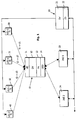
FIG. 1 shows a possible arrangement of the components for carrying out the method according to the invention; -
FIG. 2 shows the principle of applied time division multiplexing; -
FIG. 3 shows a practical example of the time-division multiplexing method according to the invention.
Der Zweck des erfindungsgemäßen Verfahrens ist es, eine Vielzahl von innerhalb eines begrenzten Areal befindlichen Objekten zu identifizieren und zu orten.
Wie in
As in
Des weiteren umfasst das System eine zentrale Komponente 20, die eine Datenverarbeitungseinrichtung 21 und eine Zeitbasis 22 umfasst und mit einer oder mehreren stationären, drahtlosen Kommunikationseinrichtungen 23, 24, in Form von Funkkommunikationseinrichtungen, verbunden ist und über diese Funksignale empfangen und aussenden kann.Furthermore, the system comprises a
Es sind eine Vielzahl von stationären Ultraschallsendern 30, 31, 32, 40 vorgesehen, die mit der zentralen Komponente 1 verbunden sind und von dieser gesteuert werden. Die US-Sender 30-32, 40 sind über ein mit US-Signalen zu überdeckendes Areal verteilt angeordnet, wobei deren Position der zentralen Komponenten 20 genau bekannt ist. Die US-Sender 30-32, 40 sind in Gruppen eingeteilt. Jede Gruppe umfasst mindestens drei US-Sender, z.B. US1-1, US2-1, US3-1, die auf einer ersten US-Frequenz f1 senden. Eine benachbarte Gruppe umfasst ebenfalls mehrere US-Sender, z.B. US2-1,..., etc, die auf einer zweiten US-Frequenz f2 senden.A plurality of stationary
Die Ortung der objektbezogenen Komponente 10 und damit des Objekts selbst erfolgt mittels einer Laufzeitmessung der von den US-Sendern 30-32, 40 abgestrahlten US-Signale zur Bestimmung der Entfernung zwischen dem an dem zu ortenden Objekt angebrachten US-Empfänger und den auf festen Positionen angebrachten US- Sendern 30-32, 40.The location of the object-related
Zur Groblokalisierung und /oder zusätzlichen Überprüfung des Ortungsergebnisses wird eine Feldstärkemessung vorgenommen. Dabei wird an den Funkempfängern 23, 24 die Feldstärke des von dem am ortenden Objekt angebrachten Funksenders 14 abgestrahlten Funksignals gemessen. Je größer die Feldstärke, desto näher ist das Objekt an dem entsprechenden Funkempfänger 23, 24.For coarse localization and / or additional verification of the location result, a field strength measurement is made. In this case, the field strength of the radio transmitter radiated by the
Mittels einer Frequenzmessung der im objektbezogenen US-Empfänger 11 empfangenen US- Signal wird zusätzlich eine Unterscheidung zwischen benachbarten Gruppen von US- Sendern (Clustern) vorgenommen.By means of a frequency measurement of the US signal received in the object-related
Erfindungsgemäß werden die Laufzeiten t1, t2, t3 der Ultraschallsignale von den einzelnen ortsfesten US-Sendern 30-32, 40 zum US-Empfänger 11 der objektbezogenen Komponente 10 gemessen. Jede Laufzeit kann aufgrund der bekannten Schallgeschwindigkeit (in Luft bei Raumtemperatur ca. 344 m/s) einer bestimmten Entfernung d1, d2, d3 zwischen dem US-Sender und dem US-Empfänger zugeordnet werden.According to the invention, the transit times t1, t2, t3 of the ultrasonic signals from the individual stationary US transmitters 30-32, 40 to the
Die ermittelten Laufzeiten t1, t2, t3 werden über das Funkkommunikationssystem 14 und 23 bzw. 24 von der objektbezogenen Komponente 10 an die zentrale Komponente 20 übertragen und dort mit Hilfe der bekannten Beziehung d = t · c, wobei c = Schallgeschwindigkeit, in dazu proportionale Entfernungen d1, d2, d3 umgesetzt. Alternativ können die Entfernungen d1, d2, d3 erfindungsgemäß auch bereits in der objektbezogenen Komponente 10 berechnet und an die zentrale Komponente 20 übertragen werden.The determined transit times t1, t2, t3 are transmitted via the
Aus diesen Entfernungswerten d1, d2, d3 lässt sich mittels bekannter geometrischer Verfahren die relative Position des objektbezogenen US-Empfängers 11 zu den US-Sendern 30-32, 40 und - falls die absolute Position der US-Sender bekannt ist - die absolute Position des US-Empfängers 11 und damit des Objekts bestimmen.From these distance values d1, d2, d3, the relative position of the object-related
Die übergeordnete zentrale Komponente 20 koordiniert also die US- Sender 30-32, 40, synchronisiert die Zeitbasen 13 auf den objektbezogenen Komponenten und steuert die Kommunikation zwischen den objektbezogenen Komponenten 10 und der zentralen Komponente 20 über das drahtlose Kommunikationssystem 14, 23,24.The higher-level
In
Jeder US-Sender US1, US2, US3 sendet sein Signal zu Beginn eines festgelegten Zeitfensters aus. Der jeweiligen Sendezeitpunkt der US-Signale wird von der zentralen Komponente gesteuert. Zum Beispiel sendet US1 im Zeitfenster 1, US2 im Zeitfenster 2, usw. Die US-Signale der US-Sender US1, US2, US3 werden im US-Empfänger UE empfangen. Hierbei sind die Zeitbasen 13 der objektbezogenen Komponenten und der zentralen Komponente 22 miteinander synchronisiert. Dies erfolgt durch den Austausch eines Synchronisierungsprotokolls über das Funkkommunikationssystem. Die US-Signale werden im US-Empfänger der objektbezogenen Komponente 10 empfangen. Dort werden aus der Empfangszeit und dem durch die Zeitfenster vorgegebenen Zeitrahmen die Laufzeiten der in den jeweiligen Zeitfenstern empfangenen US-Signale berechnet und in einem zu versendenden Broadcast-Telegramm abgespeichert. Somit kann jedes im US-Empfänger empfangene US-Signal anhand des gerade aktuellen Zeitfensters genau einem US-Sender zugeordnet werden. In einem dafür vorgesehenen Zeitfenster werden die abgespeicherten Broadcast-Telegramme von der objektbezogenen Komponenten 10 and die zentrale Komponente gesendet.In
Each US transmitter US1, US2, US3 transmits its signal at the beginning of a specified time window. The respective transmission time of the US signals is from the controlled central component. For example, US1 in the time window sends 1, US2 in the
Im US-Empfänger wird pro Zeitschlitz jeweils nur das zuerst empfangene US-Signal, d.h. das Signal mit der kürzesten Laufzeit, ausgewertet. Aus der Länge eines Zeitschlitzes ergibt sich der maximal mögliche Abstand zwischen US-Empfänger am Objekt und US- Sender. Die maximale Reichweite der US-Sender beträgt ca. 10-15 m. Die Auflösung der verwendeten Zeitbasen 13, 22 und ihre Synchronie bestimmt die Genauigkeit der Abstandsmessung und damit die Präzision der Lokalisierung. Bei der Ortsbestimmung sind Genauigkeiten im Bereich von einigen Zentimetern erreichbar.In the US receiver, only the first received US signal is received per time slot, i. the signal with the shortest runtime, evaluated. The length of a time slot results in the maximum possible distance between the US receiver on the object and the US transmitter. The maximum range of the US transmitter is about 10-15 m. The resolution of the
Die Anzahl der Zeitschlitze bestimmt die maximale Anzahl der möglichen US-Sender innerhalb der US- Reichweite und begrenzt damit die zeitliche Auflösung der Ortsbestimmung, das heißt die kürzeste Zeit zwischen zwei aufeinander folgenden Ortsbestimmungen eines bestimmten Objekts.The number of time slots determines the maximum number of possible US transmitters within the US range and thus limits the temporal resolution of the location, that is, the shortest time between two consecutive location determinations of a particular object.
Zur flächenmäßigen Abdeckung eines größeren Areals werden mehrere Sender/Empfänger des drahtlosen Kommunikationssystems und mehrere US-Sender kombiniert. Dabei wird die Zuordnung der objektbezogenen Komponente 10 zu den jeweiligen Sende-/Empfangsstationen 23, 24 des Kommunikationssystems mittels der Feldstärke der empfangenen HF-Signale vorgenommen.To cover the area of a larger area are multiple transmitter / receiver wireless communication system and several US stations combined. In this case, the assignment of the object-related
Durch den gleichzeitigen Empfang des eine Funksignals der Komponente 10 durch beide Kommunikationseinrichtungen 23 und 24 und die Auswertung der jeweiligen Feldstärke kann die zentrale Komponente ermitteln, welcher Gruppe von US-Sendern das Objekt am nächsten liegt. Befindet sich das Objekt genau an der Grenze zwischen zwei Gruppen von US-Sendern können die erfassten Laufzeiten t1, t2 und t3 von US-Sendern unterschiedlicher Gruppen stammen. Da die US-Sender benachbarter Gruppen mit verschiedener Frequenz f1 bzw. f2 senden, kann durch die Auswertung der Frequenz leicht ermittelt werden, von welcher Gruppe das einzelne US-Signal stammt.By the simultaneous reception of the one radio signal of the
Ein Zyklus des Zeitmultiplexverfahrens dauert in diesem Beispiel 10 s. Der Zyklus ist in 200 Zeitfenster von jeweils 50 ms Länge aufgeteilt. Erfindungsgemäß sind Zeit-Synchronisationsfenster S1...Sx vorgesehen, in welchen eine Datenübertragung zwischen der zentralen Komponente 20 und der objektbezogenen Komponente 10 zur Synchronisation deren Zeitbasis 13 erfolgt. Des weiteren sind Ultraschall-Sende- und Empfangsfenster U1...Uy vorgesehen, in denen das Aussenden und Empfangen der US-Signale erfolgt. Jeder US-Sender sendet nur in einem Zeitfenster Uy eines Zyklus.
In den Kommunikationsfenstern erfolgt die Funkkommunikation zwischen der zentralen Komponente 20 und einer oder mehreren bestimmten objektbezogenen Komponenten10.
Schließlich sind eine Reihe von Broadcastfenster B vorgesehen, in welchen Ortungsnachrichten, welche die Ultraschall-Laufzeiten- bzw. Distanzwerte enthalten, über das Funkkommunikationssystem von den objektbezogenen Komponenten 10 zur zentralen Komponente übermittelt werden. Jede objektbezogene Komponente sendet sein Ortungstelegramm z.B. drei mal in zufällig ausgewählten Broadcastfenstern, z.B. nach dem slotted-ALOHA-Verfahren.
Die einzelnen Zeit-Synchronisationsfenster, Ultraschall-Sende- und Empfangsfenster, Kommunikationsfenster und Broadcastfenster treten innerhalb eines Zyklus in einer in
One cycle of time division multiplexing takes 10 s in this example. The cycle is divided into 200 time slots of 50 ms each. According to the invention, time synchronization windows S1... Sx are provided, in which a data transmission takes place between the
In the communication windows, the radio communication takes place between the
Finally, a series of broadcast windows B are provided, in which location messages containing the ultrasound transit time or distance values, respectively, over the radio communication system of the object-related
The individual time synchronization windows, ultrasonic transmit and receive windows, communication windows and broadcast windows occur within a cycle in an in
Claims (12)
- Method for identifying and locating objects within a defined area,
wherein ultrasonic signals are transmitted at predetermined transmission times by one or more ultrasonic transmitters (30-32) sited at fixed locations within the area,
wherein the transmitted ultrasonic signal is received by an ultrasonic receiver (11) of a component (10) arranged in or on the object,
wherein a reception time is assigned to the received ultrasonic signal in the object-related component (10),
wherein the determined reception time is transmitted together with an object identifier via a wireless communication system (14; 23; 24) to a central component (20),
wherein a radio communication system is used as the wireless communication system, with an exchange of radio signals between a radio transceiver (14) arranged in the object-related component and a fixed radio transceiver (23, 24) connected to the central component,
wherein the transit time of the ultrasonic signal is determined in the object-related component (10) and/or in the central component (20) from the transmission time and the assigned reception time, wherein the distance between the ultrasonic transmitter and the ultrasonic receiver of the object is determined from the transit time of the ultrasonic signal,
wherein the position of the ultrasonic receiver (11) and hence that of the object is determined by known methods from the distances determined,
wherein the ultrasonic transmitters are divided into two or more groups, with all ultrasonic transmitters within a group transmitting on a specific transmission frequency (f1; f2),
characterized in that for a rough determination of the location of an object-related component on the part of the central component the reception field strength of the radio signals received from the object-related radio transmitters is determined and in that for each group a different transmission frequency from that of the adjacent group is used for the ultrasonic transmitters and in that moreover a discrimination is made between adjacent groups of ultrasonic transmitters by measuring the frequency of the ultrasonic signals received in the object-related ultrasonic receiver (11). - Method according to Claim 1, characterized in that an ultrasonic signal is transmitted at a predetermined transmission time by each of a plurality of ultrasonic transmitters (30-32) sited at fixed locations within the area, and a two- or three-dimensional determination of the object's position is carried out.
- Method according to either of Claims 1 and 2, characterized in that the transmission times for the ultrasonic signals of the individual ultrasonic transmitters (30-32) are controlled by the central component (20).
- Method according to any one of Claims 1 to 3, characterized in that a radio signal is transmitted by one of the fixed radio transceivers simultaneously with the ultrasonic signals, the transit time measurement for the transmitted ultrasonic signals being initiated by the reception of the radio signal in the object-related component.
- Method according to any one of Claims 1 to 4, characterized in that the central component and the object-related component each have a time base (22; 13), and these time bases are continuously synchronized with each other.
- Method according to Claim 5, characterized in that the time bases (22; 13) are synchronized via the wireless communication system.
- Method according to either of Claims 5 and 6, characterized in that transmission of the ultrasonic signals is effected in a constantly repeating cycle, the cycle being divided into a number of time windows and each ultrasonic transmitter being assigned a time window for transmission of its ultrasonic signal.
- Method according to any one of Claims 5 to 7, characterized in that the synchronization of the time bases is effected within a specific time window.
- Method according to any one of Claims 5 to 8, characterized in that the ultrasonic signals received by the ultrasonic receiver are assigned to the respective ultrasonic transmitter by reference to the time window prevailing at the time of their reception.
- Method according to any one of Claims 5 to 9, characterized in that only the first ultrasonic signal to be received within a time window is evaluated by the ultrasonic receiver.
- Method according to any one of Claims 1 to 10, characterized in that the ultrasonic transmitters within a group never transmit simultaneously.
- Method according to any one of Claims 7 to 11, characterized in that the exchange of radio signals is effected within a defined time window.
Applications Claiming Priority (2)
| Application Number | Priority Date | Filing Date | Title |
|---|---|---|---|
| DE10324651 | 2003-05-30 | ||
| DE10324651A DE10324651A1 (en) | 2003-05-30 | 2003-05-30 | Method and system for the identification and location of objects |
Publications (2)
| Publication Number | Publication Date |
|---|---|
| EP1482323A1 EP1482323A1 (en) | 2004-12-01 |
| EP1482323B1 true EP1482323B1 (en) | 2011-03-16 |
Family
ID=33103659
Family Applications (1)
| Application Number | Title | Priority Date | Filing Date |
|---|---|---|---|
| EP04012514A Not-in-force EP1482323B1 (en) | 2003-05-30 | 2004-05-27 | Method and system for identification and location of objects |
Country Status (3)
| Country | Link |
|---|---|
| EP (1) | EP1482323B1 (en) |
| AT (1) | ATE502312T1 (en) |
| DE (2) | DE10324651A1 (en) |
Families Citing this family (4)
| Publication number | Priority date | Publication date | Assignee | Title |
|---|---|---|---|---|
| DE102006044937B4 (en) * | 2006-09-22 | 2012-03-01 | Pepperl + Fuchs Gmbh | Device and method for determining the distance and / or the spatial position of a target object |
| GB2457600A (en) * | 2009-03-03 | 2009-08-26 | Saturn Solutions Ltd | Vehicle measurement system |
| DE102009031955B4 (en) | 2009-06-08 | 2014-04-30 | Technische Universität Dresden | Method and device for determining the spatial position of a unit to be located |
| ITMO20120157A1 (en) * | 2012-06-18 | 2013-12-19 | Microlog S R L | SYSTEM AND METHOD FOR MONITORING PERSONAL FLOWS |
Family Cites Families (9)
| Publication number | Priority date | Publication date | Assignee | Title |
|---|---|---|---|---|
| US5214615A (en) * | 1990-02-26 | 1993-05-25 | Will Bauer | Three-dimensional displacement of a body with computer interface |
| DE4036022A1 (en) * | 1990-11-13 | 1992-05-14 | Bosch Gmbh Robert | METHOD AND LOCATION DEVICE FOR LOCATING VEHICLES OF DRIVERLESS TRANSPORT SYSTEMS |
| DE4119150A1 (en) * | 1991-06-11 | 1992-12-17 | Brunner Wolfgang | Gait analyser for measuring human body movement - uses ultrasonic transmitters and receivers activated at different times, arranged on two sides of human body |
| US5412619A (en) * | 1994-04-14 | 1995-05-02 | Bauer; Will | Three-dimensional displacement of a body with computer interface |
| JPH0996672A (en) * | 1995-09-29 | 1997-04-08 | Sukuuea:Kk | Method and system for generating three-dimensional positional data |
| GB2332053B (en) * | 1997-12-04 | 2002-01-09 | Olivetti Res Ltd | Detection system for determinning positional and other information about objects |
| IL122079A (en) * | 1997-10-30 | 2002-02-10 | Netmor Ltd | Ultrasonic positioning and tracking system |
| US6292106B1 (en) * | 1998-10-13 | 2001-09-18 | Cubic Defense Systems, Inc. | Acoustical system and method for simultaneously locating and tracking multiple personnel in rooms of a building |
| US6532416B1 (en) * | 2000-05-23 | 2003-03-11 | Siemens Aktiengesellschaft | Apparatus, method and system for a wireless communication and local positioning system in an automated, industrial and/or manufacturing environment |
-
2003
- 2003-05-30 DE DE10324651A patent/DE10324651A1/en not_active Ceased
-
2004
- 2004-05-27 DE DE502004012298T patent/DE502004012298D1/en active Active
- 2004-05-27 AT AT04012514T patent/ATE502312T1/en active
- 2004-05-27 EP EP04012514A patent/EP1482323B1/en not_active Not-in-force
Also Published As
| Publication number | Publication date |
|---|---|
| ATE502312T1 (en) | 2011-04-15 |
| EP1482323A1 (en) | 2004-12-01 |
| DE502004012298D1 (en) | 2011-04-28 |
| DE10324651A1 (en) | 2004-12-23 |
Similar Documents
| Publication | Publication Date | Title |
|---|---|---|
| DE10055289B4 (en) | System for determining the position of an object | |
| DE60212580T2 (en) | Location system and method | |
| EP2845026B1 (en) | Method and arrangement for the relative position detection of stations by means of radio location | |
| DE102015208621B4 (en) | Locating device for a motor vehicle | |
| WO2005098465A2 (en) | Method for synchronising clock pulse devices | |
| DE102008010882A1 (en) | Device and method for direction estimation and / or decoding of secondary radar signals | |
| DE2032211B2 (en) | YSTEM FOR THE MONITORING OF VEHICLES | |
| WO2018059782A9 (en) | Telegram splitting-based localization | |
| US4680587A (en) | Instrument landing system | |
| DE102013019647A1 (en) | Indoor positioning by camera and optical signal | |
| EP3414591A1 (en) | Device for displaying user information and corresponding method | |
| EP1482323B1 (en) | Method and system for identification and location of objects | |
| EP3146355B1 (en) | Medical device system and a method for locating medical devices and mobile control units of said medical device system | |
| DE102017131117A1 (en) | Wireless, electronic localization system | |
| DE10142156B4 (en) | Mobile navigation apparatus for a cellular radio network and method for providing navigation information | |
| DE102006059623B3 (en) | Method and system for position determination | |
| DE102016012101A1 (en) | Method and device for position determination | |
| EP2465310A1 (en) | Method and arrangement for measuring delay of a signal between two stations of the arrangement | |
| DE102016213239B4 (en) | DEVICE FOR COMMUNICATING WITH COMMUNICATION DEVICES, CORRESPONDING COMMUNICATION DEVICE AND METHOD | |
| DE102005044498B4 (en) | tracking device | |
| CN109474891A (en) | A kind of localization method and server | |
| DE102019211812A1 (en) | Method for locating an object | |
| DE10221649A1 (en) | Position finding method e.g. for mobile RF systems, requires taking average errors of reference positions into account | |
| EP1033583A2 (en) | Method for determining the position of a mobile GSM terminal | |
| DE102012214190A1 (en) | Method for determining position of moving object i.e. persons, in inner area environment e.g. tunnel, involves assigning signal sources to distribution assemblies, and deriving position of object from combination of values and signal |
Legal Events
| Date | Code | Title | Description |
|---|---|---|---|
| PUAI | Public reference made under article 153(3) epc to a published international application that has entered the european phase |
Free format text: ORIGINAL CODE: 0009012 |
|
| AK | Designated contracting states |
Kind code of ref document: A1 Designated state(s): AT BE BG CH CY CZ DE DK EE ES FI FR GB GR HU IE IT LI LU MC NL PL PT RO SE SI SK TR |
|
| AX | Request for extension of the european patent |
Extension state: AL HR LT LV MK |
|
| 17P | Request for examination filed |
Effective date: 20050330 |
|
| AKX | Designation fees paid |
Designated state(s): AT BE BG CH CY CZ DE DK EE ES FI FR GB GR HU IE IT LI LU MC NL PL PT RO SE SI SK TR |
|
| 17Q | First examination report despatched |
Effective date: 20081114 |
|
| GRAP | Despatch of communication of intention to grant a patent |
Free format text: ORIGINAL CODE: EPIDOSNIGR1 |
|
| GRAS | Grant fee paid |
Free format text: ORIGINAL CODE: EPIDOSNIGR3 |
|
| GRAA | (expected) grant |
Free format text: ORIGINAL CODE: 0009210 |
|
| AK | Designated contracting states |
Kind code of ref document: B1 Designated state(s): AT BE BG CH CY CZ DE DK EE ES FI FR GB GR HU IE IT LI LU MC NL PL PT RO SE SI SK TR |
|
| REG | Reference to a national code |
Ref country code: GB Ref legal event code: FG4D Free format text: NOT ENGLISH |
|
| REG | Reference to a national code |
Ref country code: CH Ref legal event code: EP |
|
| REG | Reference to a national code |
Ref country code: IE Ref legal event code: FG4D |
|
| REF | Corresponds to: |
Ref document number: 502004012298 Country of ref document: DE Date of ref document: 20110428 Kind code of ref document: P |
|
| REG | Reference to a national code |
Ref country code: DE Ref legal event code: R096 Ref document number: 502004012298 Country of ref document: DE Effective date: 20110428 |
|
| REG | Reference to a national code |
Ref country code: NL Ref legal event code: VDEP Effective date: 20110316 |
|
| PG25 | Lapsed in a contracting state [announced via postgrant information from national office to epo] |
Ref country code: SE Free format text: LAPSE BECAUSE OF FAILURE TO SUBMIT A TRANSLATION OF THE DESCRIPTION OR TO PAY THE FEE WITHIN THE PRESCRIBED TIME-LIMIT Effective date: 20110316 Ref country code: GR Free format text: LAPSE BECAUSE OF FAILURE TO SUBMIT A TRANSLATION OF THE DESCRIPTION OR TO PAY THE FEE WITHIN THE PRESCRIBED TIME-LIMIT Effective date: 20110617 Ref country code: ES Free format text: LAPSE BECAUSE OF FAILURE TO SUBMIT A TRANSLATION OF THE DESCRIPTION OR TO PAY THE FEE WITHIN THE PRESCRIBED TIME-LIMIT Effective date: 20110627 |
|
| PG25 | Lapsed in a contracting state [announced via postgrant information from national office to epo] |
Ref country code: BG Free format text: LAPSE BECAUSE OF FAILURE TO SUBMIT A TRANSLATION OF THE DESCRIPTION OR TO PAY THE FEE WITHIN THE PRESCRIBED TIME-LIMIT Effective date: 20110616 Ref country code: FI Free format text: LAPSE BECAUSE OF FAILURE TO SUBMIT A TRANSLATION OF THE DESCRIPTION OR TO PAY THE FEE WITHIN THE PRESCRIBED TIME-LIMIT Effective date: 20110316 Ref country code: CY Free format text: LAPSE BECAUSE OF FAILURE TO SUBMIT A TRANSLATION OF THE DESCRIPTION OR TO PAY THE FEE WITHIN THE PRESCRIBED TIME-LIMIT Effective date: 20110316 Ref country code: SI Free format text: LAPSE BECAUSE OF FAILURE TO SUBMIT A TRANSLATION OF THE DESCRIPTION OR TO PAY THE FEE WITHIN THE PRESCRIBED TIME-LIMIT Effective date: 20110316 |
|
| REG | Reference to a national code |
Ref country code: IE Ref legal event code: FD4D |
|
| PG25 | Lapsed in a contracting state [announced via postgrant information from national office to epo] |
Ref country code: IE Free format text: LAPSE BECAUSE OF FAILURE TO SUBMIT A TRANSLATION OF THE DESCRIPTION OR TO PAY THE FEE WITHIN THE PRESCRIBED TIME-LIMIT Effective date: 20110316 Ref country code: PT Free format text: LAPSE BECAUSE OF FAILURE TO SUBMIT A TRANSLATION OF THE DESCRIPTION OR TO PAY THE FEE WITHIN THE PRESCRIBED TIME-LIMIT Effective date: 20110718 Ref country code: EE Free format text: LAPSE BECAUSE OF FAILURE TO SUBMIT A TRANSLATION OF THE DESCRIPTION OR TO PAY THE FEE WITHIN THE PRESCRIBED TIME-LIMIT Effective date: 20110316 |
|
| BERE | Be: lapsed |
Owner name: IDENTEC SOLUTIONS AG Effective date: 20110531 |
|
| PG25 | Lapsed in a contracting state [announced via postgrant information from national office to epo] |
Ref country code: RO Free format text: LAPSE BECAUSE OF FAILURE TO SUBMIT A TRANSLATION OF THE DESCRIPTION OR TO PAY THE FEE WITHIN THE PRESCRIBED TIME-LIMIT Effective date: 20110316 Ref country code: SK Free format text: LAPSE BECAUSE OF FAILURE TO SUBMIT A TRANSLATION OF THE DESCRIPTION OR TO PAY THE FEE WITHIN THE PRESCRIBED TIME-LIMIT Effective date: 20110316 Ref country code: CZ Free format text: LAPSE BECAUSE OF FAILURE TO SUBMIT A TRANSLATION OF THE DESCRIPTION OR TO PAY THE FEE WITHIN THE PRESCRIBED TIME-LIMIT Effective date: 20110316 |
|
| PG25 | Lapsed in a contracting state [announced via postgrant information from national office to epo] |
Ref country code: NL Free format text: LAPSE BECAUSE OF FAILURE TO SUBMIT A TRANSLATION OF THE DESCRIPTION OR TO PAY THE FEE WITHIN THE PRESCRIBED TIME-LIMIT Effective date: 20110316 Ref country code: MC Free format text: LAPSE BECAUSE OF NON-PAYMENT OF DUE FEES Effective date: 20110531 |
|
| REG | Reference to a national code |
Ref country code: CH Ref legal event code: PL |
|
| PLBE | No opposition filed within time limit |
Free format text: ORIGINAL CODE: 0009261 |
|
| STAA | Information on the status of an ep patent application or granted ep patent |
Free format text: STATUS: NO OPPOSITION FILED WITHIN TIME LIMIT |
|
| PG25 | Lapsed in a contracting state [announced via postgrant information from national office to epo] |
Ref country code: LI Free format text: LAPSE BECAUSE OF NON-PAYMENT OF DUE FEES Effective date: 20110531 Ref country code: CH Free format text: LAPSE BECAUSE OF NON-PAYMENT OF DUE FEES Effective date: 20110531 |
|
| 26N | No opposition filed |
Effective date: 20111219 |
|
| PG25 | Lapsed in a contracting state [announced via postgrant information from national office to epo] |
Ref country code: PL Free format text: LAPSE BECAUSE OF FAILURE TO SUBMIT A TRANSLATION OF THE DESCRIPTION OR TO PAY THE FEE WITHIN THE PRESCRIBED TIME-LIMIT Effective date: 20110316 Ref country code: DK Free format text: LAPSE BECAUSE OF FAILURE TO SUBMIT A TRANSLATION OF THE DESCRIPTION OR TO PAY THE FEE WITHIN THE PRESCRIBED TIME-LIMIT Effective date: 20110316 |
|
| PG25 | Lapsed in a contracting state [announced via postgrant information from national office to epo] |
Ref country code: BE Free format text: LAPSE BECAUSE OF NON-PAYMENT OF DUE FEES Effective date: 20110531 |
|
| REG | Reference to a national code |
Ref country code: DE Ref legal event code: R097 Ref document number: 502004012298 Country of ref document: DE Effective date: 20111219 |
|
| REG | Reference to a national code |
Ref country code: AT Ref legal event code: MM01 Ref document number: 502312 Country of ref document: AT Kind code of ref document: T Effective date: 20110527 |
|
| PG25 | Lapsed in a contracting state [announced via postgrant information from national office to epo] |
Ref country code: AT Free format text: LAPSE BECAUSE OF NON-PAYMENT OF DUE FEES Effective date: 20110527 |
|
| PG25 | Lapsed in a contracting state [announced via postgrant information from national office to epo] |
Ref country code: LU Free format text: LAPSE BECAUSE OF NON-PAYMENT OF DUE FEES Effective date: 20110527 |
|
| PG25 | Lapsed in a contracting state [announced via postgrant information from national office to epo] |
Ref country code: TR Free format text: LAPSE BECAUSE OF FAILURE TO SUBMIT A TRANSLATION OF THE DESCRIPTION OR TO PAY THE FEE WITHIN THE PRESCRIBED TIME-LIMIT Effective date: 20110316 |
|
| PG25 | Lapsed in a contracting state [announced via postgrant information from national office to epo] |
Ref country code: HU Free format text: LAPSE BECAUSE OF FAILURE TO SUBMIT A TRANSLATION OF THE DESCRIPTION OR TO PAY THE FEE WITHIN THE PRESCRIBED TIME-LIMIT Effective date: 20110316 |
|
| REG | Reference to a national code |
Ref country code: FR Ref legal event code: PLFP Year of fee payment: 13 |
|
| REG | Reference to a national code |
Ref country code: FR Ref legal event code: PLFP Year of fee payment: 14 |
|
| PGFP | Annual fee paid to national office [announced via postgrant information from national office to epo] |
Ref country code: GB Payment date: 20170524 Year of fee payment: 14 Ref country code: DE Payment date: 20170522 Year of fee payment: 14 Ref country code: FR Payment date: 20170522 Year of fee payment: 14 |
|
| PGFP | Annual fee paid to national office [announced via postgrant information from national office to epo] |
Ref country code: IT Payment date: 20170524 Year of fee payment: 14 |
|
| REG | Reference to a national code |
Ref country code: DE Ref legal event code: R119 Ref document number: 502004012298 Country of ref document: DE |
|
| GBPC | Gb: european patent ceased through non-payment of renewal fee |
Effective date: 20180527 |
|
| PG25 | Lapsed in a contracting state [announced via postgrant information from national office to epo] |
Ref country code: IT Free format text: LAPSE BECAUSE OF NON-PAYMENT OF DUE FEES Effective date: 20180527 Ref country code: DE Free format text: LAPSE BECAUSE OF NON-PAYMENT OF DUE FEES Effective date: 20181201 Ref country code: FR Free format text: LAPSE BECAUSE OF NON-PAYMENT OF DUE FEES Effective date: 20180531 Ref country code: GB Free format text: LAPSE BECAUSE OF NON-PAYMENT OF DUE FEES Effective date: 20180527 |