EP1464986B1 - Radar apparatus - Google Patents
Radar apparatus Download PDFInfo
- Publication number
- EP1464986B1 EP1464986B1 EP04251455A EP04251455A EP1464986B1 EP 1464986 B1 EP1464986 B1 EP 1464986B1 EP 04251455 A EP04251455 A EP 04251455A EP 04251455 A EP04251455 A EP 04251455A EP 1464986 B1 EP1464986 B1 EP 1464986B1
- Authority
- EP
- European Patent Office
- Prior art keywords
- signal
- antennas
- channels
- radar apparatus
- antenna
- Prior art date
- Legal status (The legal status is an assumption and is not a legal conclusion. Google has not performed a legal analysis and makes no representation as to the accuracy of the status listed.)
- Expired - Fee Related
Links
Images


Classifications
-
- G—PHYSICS
- G01—MEASURING; TESTING
- G01S—RADIO DIRECTION-FINDING; RADIO NAVIGATION; DETERMINING DISTANCE OR VELOCITY BY USE OF RADIO WAVES; LOCATING OR PRESENCE-DETECTING BY USE OF THE REFLECTION OR RERADIATION OF RADIO WAVES; ANALOGOUS ARRANGEMENTS USING OTHER WAVES
- G01S13/00—Systems using the reflection or reradiation of radio waves, e.g. radar systems; Analogous systems using reflection or reradiation of waves whose nature or wavelength is irrelevant or unspecified
- G01S13/02—Systems using reflection of radio waves, e.g. primary radar systems; Analogous systems
- G01S13/06—Systems determining position data of a target
- G01S13/42—Simultaneous measurement of distance and other co-ordinates
- G01S13/426—Scanning radar, e.g. 3D radar
-
- G—PHYSICS
- G01—MEASURING; TESTING
- G01S—RADIO DIRECTION-FINDING; RADIO NAVIGATION; DETERMINING DISTANCE OR VELOCITY BY USE OF RADIO WAVES; LOCATING OR PRESENCE-DETECTING BY USE OF THE REFLECTION OR RERADIATION OF RADIO WAVES; ANALOGOUS ARRANGEMENTS USING OTHER WAVES
- G01S7/00—Details of systems according to groups G01S13/00, G01S15/00, G01S17/00
- G01S7/02—Details of systems according to groups G01S13/00, G01S15/00, G01S17/00 of systems according to group G01S13/00
- G01S7/40—Means for monitoring or calibrating
- G01S7/4004—Means for monitoring or calibrating of parts of a radar system
- G01S7/4021—Means for monitoring or calibrating of parts of a radar system of receivers
-
- G—PHYSICS
- G01—MEASURING; TESTING
- G01S—RADIO DIRECTION-FINDING; RADIO NAVIGATION; DETERMINING DISTANCE OR VELOCITY BY USE OF RADIO WAVES; LOCATING OR PRESENCE-DETECTING BY USE OF THE REFLECTION OR RERADIATION OF RADIO WAVES; ANALOGOUS ARRANGEMENTS USING OTHER WAVES
- G01S13/00—Systems using the reflection or reradiation of radio waves, e.g. radar systems; Analogous systems using reflection or reradiation of waves whose nature or wavelength is irrelevant or unspecified
- G01S13/02—Systems using reflection of radio waves, e.g. primary radar systems; Analogous systems
- G01S13/06—Systems determining position data of a target
- G01S13/08—Systems for measuring distance only
- G01S13/32—Systems for measuring distance only using transmission of continuous waves, whether amplitude-, frequency-, or phase-modulated, or unmodulated
- G01S13/34—Systems for measuring distance only using transmission of continuous waves, whether amplitude-, frequency-, or phase-modulated, or unmodulated using transmission of continuous, frequency-modulated waves while heterodyning the received signal, or a signal derived therefrom, with a locally-generated signal related to the contemporaneously transmitted signal
- G01S13/345—Systems for measuring distance only using transmission of continuous waves, whether amplitude-, frequency-, or phase-modulated, or unmodulated using transmission of continuous, frequency-modulated waves while heterodyning the received signal, or a signal derived therefrom, with a locally-generated signal related to the contemporaneously transmitted signal using triangular modulation
-
- G—PHYSICS
- G01—MEASURING; TESTING
- G01S—RADIO DIRECTION-FINDING; RADIO NAVIGATION; DETERMINING DISTANCE OR VELOCITY BY USE OF RADIO WAVES; LOCATING OR PRESENCE-DETECTING BY USE OF THE REFLECTION OR RERADIATION OF RADIO WAVES; ANALOGOUS ARRANGEMENTS USING OTHER WAVES
- G01S13/00—Systems using the reflection or reradiation of radio waves, e.g. radar systems; Analogous systems using reflection or reradiation of waves whose nature or wavelength is irrelevant or unspecified
- G01S13/88—Radar or analogous systems specially adapted for specific applications
- G01S13/93—Radar or analogous systems specially adapted for specific applications for anti-collision purposes
- G01S13/931—Radar or analogous systems specially adapted for specific applications for anti-collision purposes of land vehicles
Definitions
- the present invention relates to an FM-CW radar apparatus that uses a frequency-modulated (FM) continuous wave (CW) as a signal for transmission and, more particularly, to a DBF radar apparatus that performs digital beam forming.
- FM frequency-modulated
- CW continuous wave
- a conventional DBF radar apparatus comprises: a transmitter section for radiating an electromagnetic wave as a transmit signal; an array antenna comprising a plurality of antenna elements for receiving, as a received signal, the electromagnetic wave reflected by an object; a plurality of input terminals connected to the respective antenna elements; an output terminal which is selectively connected by a switching means to one of the plurality of input terminals; and a receiver section in which the received signal obtained from the output terminal is downconverted by using a portion of the transmitted signal and the resulting difference signal representing the difference between the transmitted signal and the received signal is converted into a digital signal, wherein the distance to or the relative velocity of the object is detected by applying prescribed processing to the digital signal obtained from the receiver section (refer, for example, to Publication of Japanese Unexamined Patent Application No. 11-160423).
- EP-A-1076244 Another example of such a system is disclosed in EP-A-1076244.
- a frequency modulated, continuous wave radar apparatus that performs Doppler beam forming, and which radiates a transmit signal from a transmitter section, and receives said transmit signal reflected from an object by switching between a plurality of antennas, wherein said plurality of antennas are divided into a plurality of groups, and wherein said radar apparatus comprises: a selector switch section having a plurality of selector switches each for sequentially and selectively switching output terminals of said plurality of antennas contained in a corresponding one of said groups for connection to an input terminal; a plurality of channels each having an A/D converter and a downconverting section for downconverting a received signal that has been input from each of said antennas to said input terminal via a corresponding one of said plurality of selector switches; and a digital signal processing section for receiving an output from said A/D converter of each of said channels, to detect the distance to or from the relative velocity of said object; characterized in that at least one of the plurality of antennas contained in each of said
- An FM-CW radar measures the distance to a target object, such as a vehicle traveling ahead, by transmitting a continuous wave frequency-modulated, for example, in a triangular pattern. More specifically, the transmitted wave from the radar is reflected by the vehicle ahead, and the reflected signal is received and mixed with the transmitted signal to produce a beat signal (radar signal). This beat signal is fast Fourier transformed to analyze the frequency. The frequency-analyzed beat signal exhibits a peak at which power becomes large in correspondence with the target. The frequency corresponding to this peak is called the peak frequency. The peak frequency carries information about distance, and the peak frequency differs between the rising portion and falling portion of the triangular FM-CW wave due to the Doppler effect associated with the relative velocity with respect to the vehicle ahead.
- the distance and relative velocity with respect to the vehicle ahead are obtained from the peak frequencies in the rising and falling portions. If there are more than one vehicle traveling ahead, a pair of peak frequencies in the rising and falling portions is generated for each vehicle. Forming pairs of peak frequencies in the rising and falling portions is called pairing.
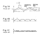
- Figs. 1A, 1B, and 1C are diagrams for explaining the principle of the FM-CW radar when the relative velocity with respect to the target is 0.
- the transmitted wave is a triangular wave whose frequency changes as shown by a solid line in Fig. 1A.
- f0 is the center frequency of the transmitted wave
- ⁇ f is the FM modulation width
- Tm is the repetition period.
- the transmitted wave is reflected from the target and received by an antenna; the received wave is shown by a dashed line in Fig. 1A.
- the received wave is shifted in frequency from the transmitted signal (i.e., produces a beat) according to the distance between the radar and the target.
- the frequency component fb of the beat signal can be expressed by the following equation.
- Figs. 2A, 2B, and 2C are diagrams for explaining the principle of the FM-CW radar when the relative velocity with respect to the target is v.
- the frequency of the transmitted wave changes as shown by a solid line in Fig. 2A.
- the transmitted wave is reflected from the target and received by the antenna; the received wave is shown by a dashed line in Fig. 2A.
- the received wave is shifted in frequency from the transmitted signal (i.e., produces a beat) according to the distance between the radar and the target.
- the beat frequency component fb can be expressed by the following equation.
- fr ⁇ fd ( 4 ⁇ ⁇ f / C ⁇ Tm ) r ⁇ ( 2 ⁇ f 0 / C ) v
- fr is the frequency due to the distance
- fd is the frequency due to the velocity
- fb Transmit beat frequency fr: Range (distance) frequency
- fd Velocity frequency
- f0 Center frequency of transmitted wave
- ⁇ f Frequency modulation width
- Tm Period of modulation wave
- C Velocity of light (velocity of radio wave)
- T Round trip time of radio wave to and from target object
- r Range (distance) to target object
- v Relative velocity with respect to target object
- Fig. 3 is a diagram showing one configuration example of the FM-CW radar.
- a modulating signal generator MOD applies a modulating signal to a voltage-controlled oscillator VCO for frequency modulation, and the frequency-modulated wave is transmitted out from a transmitting antenna AT, while a portion of the transmitted signal is separated and fed into a mixer MIX.
- the signal reflected from the target is received by a receiving antenna AR, and the received signal is mixed in the mixer MIX with the output signal of the voltage-controlled oscillator VCO to produce a beat signal.
- the beat signal is passed through a filter F, and is converted by an A/D converter into a digital signal; the digital signal is then supplied to a digital signal processor DSP where signal processing, such as a fast Fourier transform, is applied to the digital signal to obtain the distance and the relative velocity.
- DSP digital signal processor
- Digital beam forming is a technology in which signals received by an array antenna with a plurality of receiving antennas are each A/D converted and fed to a digital signal processing section and adjustments of beam scanning and sidelobe characteristics, etc. are made in the digital signal processing section.
- a DBF radar accomplishes the function of phase shifters in a phased-array antenna radar by digital signal processing; the basic configuration of the DBF radar is shown in Fig. 4.
- a modulating signal generator MOD applies a modulating signal to a voltage-controlled oscillator VCO for frequency modulation, and the frequency-modulated wave is transmitted out from a transmitting antenna AT, while a portion of the transmitted signal is separated and fed into a plurality of mixers MIX1 to MIXn.
- Signals reflected from objects are received by a plurality of receiving antennas AR1 to ARn, and the received signals from the respective receiving antennas are fed via respective amplifiers AMP1 to AMPn into the respective mixers MIX1 to MIXn where the received signals are each mixed with the output signal of the voltage-controlled oscillator VCO to produce beat signals.
- the beat signals thus produced are passed through respective filters F1 to Fn and are converted by respective A/D converters A/D1 to A/Dn into digital signals which are supplied to a digital signal processor DSP.
- DSP digital signal processor
- phase shifting PLCFT
- the feature of DBF is that a plurality of beams can be created in a single acquisition process because, once the signals from all the receiving antennas are taken in as digital signals, the beam can be synthesized in any desired direction based on the digital signals.
- reference numeral 1 is a transmitter section
- 2 is an antenna section
- 3 is a selector switch section
- 4 is a receiver section
- 5 is a digital signal processing section.
- the modulating signal generator MOD applies a modulating signal to the voltage-controlled oscillator VCO for frequency modulation, and the frequency-modulated wave of f0 ⁇ f/2 is transmitted out from the transmitting antenna AT, while a portion of the transmitted signal is separated and fed into a mixer 42 in the receiver section 4.
- Signals reflected from objects are received by the plurality of receiving antennas AR1 to ARn in the antenna section 2, and the received signals from the respective receiving antennas are fed via the selector switch section 3 into the receiver section 4.
- the receiving antennas comprise n receiving antennas AR1 to ARn corresponding to the first channel ch1 to the nth channel chn.
- the selector switch section 3 comprises n terminal outputs t1 to tn corresponding to the n antennas and one input terminal T which is connected to one of the terminals t1 to tn, the connection being switched cyclically by a switching signal supplied from a switching signal generator 46.
- the signals received by the receiving antennas are each amplified by an amplifier 41 and mixed in the mixer 42 with a portion of the transmitted signal. With this mixing, the received signal is downconverted to produce a beat signal which is the difference between the transmitted signal and the received signal.
- the beat signal is then passed through an amplifier 43 and a filter 44 and input to an A/D converter 45 where it is converted into a digital signal in synchronism with the timing of the switching signal output from the switching signal generator 46.
- the digital signal processing section (DSP) 5 performs digital beam forming by taking the digital beat signal from the A/D converter 45 as an input.
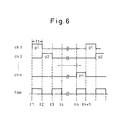
- this switching signal is a clock signal of frequency fsw, and channel switching occurs at each of the rising and falling edges of the switching signal with the frequency of fsw, as shown by p1 to pn on ch1 to chn.
- ch1 is selected during p1 (time t1 to t2)
- ch2 is selected during p2 (time t2 to t3)
- chn is selected during pn (time tn to tn+1) in sequence for connection to the amplifier 41.
- the time interval of each of the periods p1 to pn is the same, i.e., T1, and the channels are switched one after another with the period T1, as shown in Fig. 6.
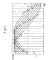
- the waveforms of the signals downconverted by the mixer 42 are shown in Fig. 7.
- the time is plotted along the abscissa and the voltage along the ordinate.
- Vertical lines are drawn with a spacing equal to the channel switching period T1 with which the selector switch performs switching.
- the eight curves show the beat signals produced by downconverting the signals received on the respective channels.
- the beat signals output from the mixer 42 have the waveforms shown by thick lines in Fig. 7.
- Each beat signal is passed through the amplifier 43 and the filter 44 and input to the A/D converter 45.
- the beat signal is converted into a digital signal which is supplied to the digital signal processor (DSP) 5.
- DSP digital signal processor
- phase shifting P-SFT
- P-SFT phase shifting
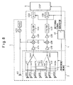
- Fig. 8 shows an embodiment of the radar apparatus of the present invention.
- This radar apparatus differs from the radar apparatus of Fig. 5 in that a plurality of channels each having a downconverting section are provided in the receiver section 4, with provisions made to share at least one of the plurality of antennas between the plurality of channels.
- Fig. 8 two downconverting sections are provided, and reference numeral 1 indicates the transmitter section, 2 the antenna section, 3 the selector switch section, 4 the receiver section, and 5 the digital signal processing section (DSP).
- the modulating signal generator MOD applies a modulating signal to the voltage-controlled oscillator VCO for frequency modulation, and the frequency-modulated wave of f0 ⁇ f/2 is transmitted out from the transmitting antenna AT, while a portion of the transmitted signal is separated and fed into mixers 42A and 42B in the receiver section 4.
- Signals reflected from objects are received by the plurality of receiving antennas in the antenna section 2, and the received signals from the respective receiving antennas are fed via the selector switch section 3 into the receiver section 4.
- the receiving antennas are divided into two groups, group A consisting of n receiving antennas AR11 to AR1n and group B consisting of n receiving antennas AR21 to AR2n.
- the antenna section 2 further includes a common antenna AR0 connected to a branching means hereinafter described.
- the selector switch section 3 includes output terminals t11 to t1n of the antennas in the group A, output terminals t21 to t2n of the antennas in the group B, and terminals t01 and t02 of the branching means 31.
- SW1 is a selector switch for the group A, by which the connection to the terminals t11 to t1n and t01 is sequentially switched with a prescribed period to sequentially input the received signals from the respective antennas AR11 to AR1n and the common antenna AR0 into the receiver section.
- SW2 is a selector switch for group B, by which the connection to the terminals t21 to t2n and t02 is sequentially switched with a prescribed period to sequentially input the received signals from the respective antennas AR21 to AR2n and the common antenna AR0 into the receiver section.
- the branching means 31 includes a selector switch SW0 by which the output of the common antenna AR0 is switched between the terminal t01 and the terminal t02.
- a hybrid circuit may be used as the branching means.
- the receiver section 4 comprises two channels: channel A includes an amplifier 41A, a mixer 42A as a downconverter, an amplifier 43A, a filter 44A, and an A/D converter 45A, and channel B includes an amplifier 41B, a mixer 42B as a downconverter, an amplifier 43B, a filter 44B, and an A/D converter 45B.
- the number of channels is 2, but three or more channels may be provided.
- the receiving antennas are divided into the same number of groups as there are channels, and the number of common antennas and branching means is increased as the number of channels increases.
- the received signals input from the antennas AR11 to AR1n and the common antenna AR0 in the antenna section 2 are sequentially and selectively switched by SW1 for input to the channel A in the receiver section 4, and likewise, the received signals input from the antennas AR21 to AR2n and the common antenna AR0 are sequentially and selectively switched by SW2 for input to the channel B in the receiver section 4.
- SW1 and SW2 are controlled by the clock signal of frequency fsw shown, for example, in Fig. 6, that is output from the switching signal generator 46. Switching from one antenna to the next occurs at each of the rising and falling edges of the clock signal, that is, the channel switching is performed with the period T1.
- the signal output from the amplifier 41A is fed into the mixer 42A acting as the downconverter, where the signal is downconverted by being mixed with the output signal of the voltage-controlled oscillator VCO, and a beat signal is thus produced.
- the waveform of the downconverted signal is the same as that shown in Fig. 7.
- the beat signal whose waveform is shown by a thick line in Fig. 7 is then passed through the' amplifier 43A and the filter 44A and input to the A/D converter 45A. In the A/D converter 45A, the beat signal is converted into a digital signal which is supplied to the digital signal processor (DPS) 5.
- DPS digital signal processor
- the received signals input from the antennas AR21 to AR2n and the common antenna AR0 in the antenna section 2 are sequentially and selectively switched by SW2 for input to the channel B in the receiver section 4.
- the remainder of the operation is the same as that described for the channel A.
- the common antenna AR0 is shared between the two channels A and B each having a downconverter.
- one antenna is shared, but two or more antennas may be shared.
- the received signal obtained via the switch SW1 is downconverted and A/D converted on the channel A and input to the DSP 5 for processing.
- the received signal fed via the switch SW2 is downconverted and A/D converted on the channel B and input to the DSP 5 for processing.
- the characteristics of the mixers, etc. vary depending on the surrounding environment such as temperature, and an accurate measurement may not be accomplished. According to the present invention, since corrections are applied in such cases, the accuracy of measurement can be enhanced.
- FIG. 10 shows the case where the number of channels is 3 in the radar apparatus of the present invention.
- Antennas (1) to (9) are divided into three groups (A), (B), and (C), and the receiver section comprises three channels (A), (B), and (C).
- the number of antennas in each group is three or four, but the invention is not limited to this particular number.
- Figs. 11A and 11B show how corrections are applied.
- Fig. 11A shows the received signals fed via the switches SW1 to SW3 to the respective channels (A), (B), and (C) for the case where corrections are applied.
- the received signals from the antennas (1) to (3) are input to the channel (A)
- the received signals from the antennas (3) to (6) are input to the channel (B)
- the received signals from the antennas (6) to (9) are input to the channel (C).
- the received signal from the antenna (3) is input to both the channels (A) and (B), and the received signal from the antenna (6) is input to both the channels (B) and (C).
- Fig. 11B shows the received signals fed via the switches SW1 to SW3 to the respective channels (A), (B), and (C) for the case where corrections are not applied. As shown in Fig. 11B, no antennas are shared between the respective channels.
- corrections can be applied when a temperature change is detected, or at predetermined intervals of time.
- a method for reducing the number of channels to be switched within one data acquisition sector (measuring sector) for the same number of antenna arrays is disclosed, for example, in Publication of Japanese Unexamined Patent Application No. 11-311668.
- combinations must be considered, and processing for synthesis must be performed using data from a plurality of sectors (a plurality of Frequency Modulations).
- one antenna array is shared between a plurality of channels, and beat signals are produced on different channels for the same received signal, based on the analysis results of which the correlations of the phase and amplitude characteristics between the respective receive channels are obtained; this configuration serves to prevent accuracy degradation even when the surrounding environment changes.
Landscapes
- Engineering & Computer Science (AREA)
- Radar, Positioning & Navigation (AREA)
- Remote Sensing (AREA)
- Computer Networks & Wireless Communication (AREA)
- Physics & Mathematics (AREA)
- General Physics & Mathematics (AREA)
- Radar Systems Or Details Thereof (AREA)
Description
- The present invention relates to an FM-CW radar apparatus that uses a frequency-modulated (FM) continuous wave (CW) as a signal for transmission and, more particularly, to a DBF radar apparatus that performs digital beam forming.
- A conventional DBF radar apparatus comprises: a transmitter section for radiating an electromagnetic wave as a transmit signal; an array antenna comprising a plurality of antenna elements for receiving, as a received signal, the electromagnetic wave reflected by an object; a plurality of input terminals connected to the respective antenna elements; an output terminal which is selectively connected by a switching means to one of the plurality of input terminals; and a receiver section in which the received signal obtained from the output terminal is downconverted by using a portion of the transmitted signal and the resulting difference signal representing the difference between the transmitted signal and the received signal is converted into a digital signal, wherein the distance to or the relative velocity of the object is detected by applying prescribed processing to the digital signal obtained from the receiver section (refer, for example, to Publication of Japanese Unexamined Patent Application No. 11-160423).
- Another example of such a system is disclosed in EP-A-1076244.
- It is an object of the present invention to provide a DBF radar apparatus that can accomplish highly accurate measurements.
- In accordance with the present invention, a frequency modulated, continuous wave radar apparatus that performs Doppler beam forming, and which radiates a transmit signal from a transmitter section, and receives said transmit signal reflected from an object by switching between a plurality of antennas, is provided, wherein
said plurality of antennas are divided into a plurality of groups, and wherein
said radar apparatus comprises: a selector switch section having a plurality of selector switches each for sequentially and selectively switching output terminals of said plurality of antennas contained in a corresponding one of said groups for connection to an input terminal; a plurality of channels each having an A/D converter and a downconverting section for downconverting a received signal that has been input from each of said antennas to said input terminal via a corresponding one of said plurality of selector switches; and a digital signal processing section for receiving an output from said A/D converter of each of said channels, to detect the distance to or from the relative velocity of said object; characterized in that at least one of the plurality of antennas contained in each of said groups is a common antenna, the or each common antenna forming part of at least two of said groups, and in that the digital signal processing section is further adapted to apply corrections based on the correlation between the respective outputs of each of said channels which received the same signal from said at least one common antenna. - According to the present invention, as at least one of the plurality of antennas is shared between the plurality of channels, highly accurate measurements can be accomplished by applying corrections.
- The above object and features of the present invention will be more apparent from the following description of the preferred embodiments with reference to the accompanying drawings, wherein:
- Figs. 1A, 1B, and 1C are diagrams for explaining the principle of FM-CW radar when the relative velocity with respect to target is 0;
- Figs, 2A, 2B, and 2C are diagrams for explaining the principle of FM-CW radar when the relative velocity with respect to target is v;
- Fig. 3 is a diagram showing one configuration example of the FM-CW radar;
- Fig. 4 is a diagram showing the basic configuration of a digital beam forming (DBF) radar;
- Fig. 5 is a diagram showing a modified example of the digital beam forming (DBF) radar;
- Fig. 6 is a diagram showing a signal output from a switching signal generator and a waveform for explaining antenna switching operation;
- Fig. 7 is a diagram showing the waveforms of downconverted signals;
- Fig. 8 is a diagram showing an embodiment of a radar apparatus according to the present invention;
- Fig. 9 is a diagram showing the configuration of a branching means;
- Fig. 10 is a diagram showing a radar apparatus according to the present invention for the case where the number of channels is 3; and
- Figs. 11A and 11B are diagrams for explaining how corrections are applied.
- Before describing the radar apparatus of the present invention, the principle of FM-CW radar and the principle of DBF radar will be described.
- An FM-CW radar measures the distance to a target object, such as a vehicle traveling ahead, by transmitting a continuous wave frequency-modulated, for example, in a triangular pattern. More specifically, the transmitted wave from the radar is reflected by the vehicle ahead, and the reflected signal is received and mixed with the transmitted signal to produce a beat signal (radar signal). This beat signal is fast Fourier transformed to analyze the frequency. The frequency-analyzed beat signal exhibits a peak at which power becomes large in correspondence with the target. The frequency corresponding to this peak is called the peak frequency. The peak frequency carries information about distance, and the peak frequency differs between the rising portion and falling portion of the triangular FM-CW wave due to the Doppler effect associated with the relative velocity with respect to the vehicle ahead. The distance and relative velocity with respect to the vehicle ahead are obtained from the peak frequencies in the rising and falling portions. If there are more than one vehicle traveling ahead, a pair of peak frequencies in the rising and falling portions is generated for each vehicle. Forming pairs of peak frequencies in the rising and falling portions is called pairing.
- Figs. 1A, 1B, and 1C are diagrams for explaining the principle of the FM-CW radar when the relative velocity with respect to the target is 0. The transmitted wave is a triangular wave whose frequency changes as shown by a solid line in Fig. 1A. In the figure, f0 is the center frequency of the transmitted wave, Δf is the FM modulation width, and Tm is the repetition period. The transmitted wave is reflected from the target and received by an antenna; the received wave is shown by a dashed line in Fig. 1A. The round trip time T to and from the target is given by T = 2r/C, where r is the distance (range) to the target and C is the velocity of radio wave propagation.
- Here, the received wave is shifted in frequency from the transmitted signal (i.e., produces a beat) according to the distance between the radar and the target.
- The frequency component fb of the beat signal can be expressed by the following equation.

where fr is the frequency due to the range (distance). - Figs. 2A, 2B, and 2C, on the other hand, are diagrams for explaining the principle of the FM-CW radar when the relative velocity with respect to the target is v. The frequency of the transmitted wave changes as shown by a solid line in Fig. 2A. The transmitted wave is reflected from the target and received by the antenna; the received wave is shown by a dashed line in Fig. 2A. Here, the received wave is shifted in frequency from the transmitted signal (i.e., produces a beat) according to the distance between the radar and the target. In this case, as the relative velocity with respect to the target is v, a Doppler shift occurs, and the beat frequency component fb can be expressed by the following equation.

where fr is the frequency due to the distance, and fd is the frequency due to the velocity. - The symbols in the above equation have the following meanings.
fb: Transmit beat frequency
fr: Range (distance) frequency
fd: Velocity frequency
f0: Center frequency of transmitted wave
Δf: Frequency modulation width
Tm: Period of modulation wave
C: Velocity of light (velocity of radio wave)
T: Round trip time of radio wave to and from target object
r: Range (distance) to target object
v: Relative velocity with respect to target object - Fig. 3 is a diagram showing one configuration example of the FM-CW radar. As shown, a modulating signal generator MOD applies a modulating signal to a voltage-controlled oscillator VCO for frequency modulation, and the frequency-modulated wave is transmitted out from a transmitting antenna AT, while a portion of the transmitted signal is separated and fed into a mixer MIX. The signal reflected from the target is received by a receiving antenna AR, and the received signal is mixed in the mixer MIX with the output signal of the voltage-controlled oscillator VCO to produce a beat signal. The beat signal is passed through a filter F, and is converted by an A/D converter into a digital signal; the digital signal is then supplied to a digital signal processor DSP where signal processing, such as a fast Fourier transform, is applied to the digital signal to obtain the distance and the relative velocity.
- Digital beam forming is a technology in which signals received by an array antenna with a plurality of receiving antennas are each A/D converted and fed to a digital signal processing section and adjustments of beam scanning and sidelobe characteristics, etc. are made in the digital signal processing section.
- A DBF radar accomplishes the function of phase shifters in a phased-array antenna radar by digital signal processing; the basic configuration of the DBF radar is shown in Fig. 4.
- As shown, a modulating signal generator MOD applies a modulating signal to a voltage-controlled oscillator VCO for frequency modulation, and the frequency-modulated wave is transmitted out from a transmitting antenna AT, while a portion of the transmitted signal is separated and fed into a plurality of mixers MIX1 to MIXn. Signals reflected from objects are received by a plurality of receiving antennas AR1 to ARn, and the received signals from the respective receiving antennas are fed via respective amplifiers AMP1 to AMPn into the respective mixers MIX1 to MIXn where the received signals are each mixed with the output signal of the voltage-controlled oscillator VCO to produce beat signals.
- The beat signals thus produced are passed through respective filters F1 to Fn and are converted by respective A/D converters A/D1 to A/Dn into digital signals which are supplied to a digital signal processor DSP. In the DSP, phase shifting (PH-SFT) is applied to the digital signal from each channel, and all the channels are combined.
- The feature of DBF is that a plurality of beams can be created in a single acquisition process because, once the signals from all the receiving antennas are taken in as digital signals, the beam can be synthesized in any desired direction based on the digital signals.
- On the other hand, Publication of Japanese Unexamined Patent Application No. 11-160423 discloses a DBF radar apparatus in which one amplifier, mixer, filter, etc., provided for each antenna in the DBF radar apparatus shown in Fig. 4, are consolidated into one. To make understanding of the present invention easy, such a radar apparatus will be explained with reference to Fig. 5.
- In Fig. 5,
reference numeral 1 is a transmitter section, 2 is an antenna section, 3 is a selector switch section, 4 is a receiver section, and 5 is a digital signal processing section. In thetransmitter section 1, the modulating signal generator MOD applies a modulating signal to the voltage-controlled oscillator VCO for frequency modulation, and the frequency-modulated wave of f0±Δf/2 is transmitted out from the transmitting antenna AT, while a portion of the transmitted signal is separated and fed into amixer 42 in thereceiver section 4. Signals reflected from objects are received by the plurality of receiving antennas AR1 to ARn in theantenna section 2, and the received signals from the respective receiving antennas are fed via theselector switch section 3 into thereceiver section 4. - The receiving antennas comprise n receiving antennas AR1 to ARn corresponding to the first channel ch1 to the nth channel chn. The
selector switch section 3 comprises n terminal outputs t1 to tn corresponding to the n antennas and one input terminal T which is connected to one of the terminals t1 to tn, the connection being switched cyclically by a switching signal supplied from aswitching signal generator 46. The signals received by the receiving antennas are each amplified by anamplifier 41 and mixed in themixer 42 with a portion of the transmitted signal. With this mixing, the received signal is downconverted to produce a beat signal which is the difference between the transmitted signal and the received signal. The beat signal is then passed through anamplifier 43 and afilter 44 and input to an A/D converter 45 where it is converted into a digital signal in synchronism with the timing of the switching signal output from theswitching signal generator 46. The digital signal processing section (DSP) 5 performs digital beam forming by taking the digital beat signal from the A/D converter 45 as an input. - Connection switching is performed using the signal output from the
switching signal generator 46. As shown in Fig. 6, this switching signal is a clock signal of frequency fsw, and channel switching occurs at each of the rising and falling edges of the switching signal with the frequency of fsw, as shown by p1 to pn on ch1 to chn. With this switching, ch1 is selected during p1 (time t1 to t2), ch2 is selected during p2 (time t2 to t3), and in like manner chn is selected during pn (time tn to tn+1) in sequence for connection to theamplifier 41. The time interval of each of the periods p1 to pn is the same, i.e., T1, and the channels are switched one after another with the period T1, as shown in Fig. 6. - The waveforms of the signals downconverted by the
mixer 42 are shown in Fig. 7. In Fig. 7, the time is plotted along the abscissa and the voltage along the ordinate. Vertical lines are drawn with a spacing equal to the channel switching period T1 with which the selector switch performs switching. The figure shows the case where the number of receive channels n = 8; as shown, the phases of the beat signals received from the respective channels ch1 to ch8 are slightly shifted from each other. The eight curves show the beat signals produced by downconverting the signals received on the respective channels. In this embodiment, as the channel switching is performed with the period T1 based on the signal output from theswitching signal generator 46, the beat signals output from themixer 42 have the waveforms shown by thick lines in Fig. 7. Each beat signal is passed through theamplifier 43 and thefilter 44 and input to the A/D converter 45. In the A/D converter 45, the beat signal is converted into a digital signal which is supplied to the digital signal processor (DSP) 5. In the DSP, phase shifting (PH-SFT) is applied to the digital signal from each channel, and all the channels are combined. - Fig. 8 shows an embodiment of the radar apparatus of the present invention. This radar apparatus differs from the radar apparatus of Fig. 5 in that a plurality of channels each having a downconverting section are provided in the
receiver section 4, with provisions made to share at least one of the plurality of antennas between the plurality of channels. - In Fig. 8, two downconverting sections are provided, and
reference numeral 1 indicates the transmitter section, 2 the antenna section, 3 the selector switch section, 4 the receiver section, and 5 the digital signal processing section (DSP). In thetransmitter section 1, the modulating signal generator MOD applies a modulating signal to the voltage-controlled oscillator VCO for frequency modulation, and the frequency-modulated wave of f0±Δf/2 is transmitted out from the transmitting antenna AT, while a portion of the transmitted signal is separated and fed intomixers receiver section 4. Signals reflected from objects are received by the plurality of receiving antennas in theantenna section 2, and the received signals from the respective receiving antennas are fed via theselector switch section 3 into thereceiver section 4. - The receiving antennas are divided into two groups, group A consisting of n receiving antennas AR11 to AR1n and group B consisting of n receiving antennas AR21 to AR2n. The
antenna section 2 further includes a common antenna AR0 connected to a branching means hereinafter described. - The
selector switch section 3 includes output terminals t11 to t1n of the antennas in the group A, output terminals t21 to t2n of the antennas in the group B, and terminals t01 and t02 of the branchingmeans 31. SW1 is a selector switch for the group A, by which the connection to the terminals t11 to t1n and t01 is sequentially switched with a prescribed period to sequentially input the received signals from the respective antennas AR11 to AR1n and the common antenna AR0 into the receiver section. Likewise, SW2 is a selector switch for group B, by which the connection to the terminals t21 to t2n and t02 is sequentially switched with a prescribed period to sequentially input the received signals from the respective antennas AR21 to AR2n and the common antenna AR0 into the receiver section. - The branching means 31, as shown in Fig. 9, includes a selector switch SW0 by which the output of the common antenna AR0 is switched between the terminal t01 and the terminal t02. Alternatively, a hybrid circuit may be used as the branching means.
- On the other hand, the
receiver section 4 comprises two channels: channel A includes anamplifier 41A, amixer 42A as a downconverter, anamplifier 43A, afilter 44A, and an A/D converter 45A, and channel B includes anamplifier 41B, amixer 42B as a downconverter, anamplifier 43B, afilter 44B, and an A/D converter 45B. - In Fig. 8, the number of channels is 2, but three or more channels may be provided. In that case, the receiving antennas are divided into the same number of groups as there are channels, and the number of common antennas and branching means is increased as the number of channels increases.
- The received signals input from the antennas AR11 to AR1n and the common antenna AR0 in the
antenna section 2 are sequentially and selectively switched by SW1 for input to the channel A in thereceiver section 4, and likewise, the received signals input from the antennas AR21 to AR2n and the common antenna AR0 are sequentially and selectively switched by SW2 for input to the channel B in thereceiver section 4. - The switching operations of SW1 and SW2 are controlled by the clock signal of frequency fsw shown, for example, in Fig. 6, that is output from the
switching signal generator 46. Switching from one antenna to the next occurs at each of the rising and falling edges of the clock signal, that is, the channel switching is performed with the period T1. - The signal output from the
amplifier 41A is fed into themixer 42A acting as the downconverter, where the signal is downconverted by being mixed with the output signal of the voltage-controlled oscillator VCO, and a beat signal is thus produced. The waveform of the downconverted signal is the same as that shown in Fig. 7. The beat signal whose waveform is shown by a thick line in Fig. 7 is then passed through the'amplifier 43A and thefilter 44A and input to the A/D converter 45A. In the A/D converter 45A, the beat signal is converted into a digital signal which is supplied to the digital signal processor (DPS) 5. - The received signals input from the antennas AR21 to AR2n and the common antenna AR0 in the
antenna section 2 are sequentially and selectively switched by SW2 for input to the channel B in thereceiver section 4. The remainder of the operation is the same as that described for the channel A. - As shown in Fig. 8, of the plurality of antennas, the common antenna AR0 is shared between the two channels A and B each having a downconverter. In the embodiment of Fig. 8, one antenna is shared, but two or more antennas may be shared.
- Next, the operation of the embodiment of the present invention shown in Fig. 8 will be described. The received signal obtained via the switch SW1 is downconverted and A/D converted on the channel A and input to the
DSP 5 for processing. Likewise, the received signal fed via the switch SW2 is downconverted and A/D converted on the channel B and input to theDSP 5 for processing. - In a radar apparatus, the characteristics of the mixers, etc. vary depending on the surrounding environment such as temperature, and an accurate measurement may not be accomplished. According to the present invention, since corrections are applied in such cases, the accuracy of measurement can be enhanced.
- Referring to Fig. 10 and Figs. 11A and 11B, a description will be given, below, of how corrections are applied in the radar apparatus of the present invention. Fig. 10 shows the case where the number of channels is 3 in the radar apparatus of the present invention. Antennas (1) to (9) are divided into three groups (A), (B), and (C), and the receiver section comprises three channels (A), (B), and (C). In the figure, the number of antennas in each group is three or four, but the invention is not limited to this particular number.
- Figs. 11A and 11B show how corrections are applied. Fig. 11A shows the received signals fed via the switches SW1 to SW3 to the respective channels (A), (B), and (C) for the case where corrections are applied. As shown in Fig. 11A, the received signals from the antennas (1) to (3) are input to the channel (A), the received signals from the antennas (3) to (6) are input to the channel (B), and the received signals from the antennas (6) to (9) are input to the channel (C).
- Here, the received signal from the antenna (3) is input to both the channels (A) and (B), and the received signal from the antenna (6) is input to both the channels (B) and (C).
- When a designated one of the plurality of antennas is shared between each of the plurality of channels as shown above, correlations of the phase and amplitude characteristics between the respective channels can be obtained by producing beat signals on different channels for the same received signal, and corrections can be applied based on the correlations. As a result, the accuracy of measurement does not degrade even when the surrounding environment changes.
- On the other hand, Fig. 11B shows the received signals fed via the switches SW1 to SW3 to the respective channels (A), (B), and (C) for the case where corrections are not applied. As shown in Fig. 11B, no antennas are shared between the respective channels.
- Since, usually, the surrounding environment changes sufficiently slowly compared with the observation time, data collection for inter-channel corrections need not be performed for each observation. Accordingly, corrections can be applied when a temperature change is detected, or at predetermined intervals of time.
- When only one channel comprising the downconverter mixer, etc. is provided for the plurality of antenna arrays as in the configuration of Fig. 5, switching must be performed at high speed within the measuring sector so as not to disrupt the correlation between the respective antenna arrays, and the resulting signals are as shown in Fig. 7. If each signal waveform resulting from such high-speed switching is to be faithfully input to the A/D converter, the bandwidth becomes much wider than the actual beat signal bandwidth, and this can result in a degradation of the S/N ratio.
- A method for reducing the number of channels to be switched within one data acquisition sector (measuring sector) for the same number of antenna arrays is disclosed, for example, in Publication of Japanese Unexamined Patent Application No. 11-311668. In this case, after first setting the reference channel, combinations must be considered, and processing for synthesis must be performed using data from a plurality of sectors (a plurality of Frequency Modulations).
- When applications as automotive radars are considered, there are many target objects having large level variations and large relative velocity, and it is difficult to ensure simultaneity; besides, problems associated with measurement errors or sensitivity are highly likely to occur. Even in applications where such problems do not occur, if the number of observation sectors can be reduced, the number of detection results (detected information) that can be obtained within the total observation time increases; as a result, it becomes possible to apply processing such as averaging, and this serves to enhance the detection accuracy and sensitivity.
- However, if the number of channels is simply increased (for example, the configuration of Fig. 4), the system becomes more susceptible to changes in the surrounding environment because of the temperature and frequency characteristics of the mixer, etc. provided in each channel, and the accuracy degrades as the phase and amplitude relations between the respective channels change. To solve this problem, in the present invention, one antenna array is shared between a plurality of channels, and beat signals are produced on different channels for the same received signal, based on the analysis results of which the correlations of the phase and amplitude characteristics between the respective receive channels are obtained; this configuration serves to prevent accuracy degradation even when the surrounding environment changes.
Claims (4)
- A frequency modulated, continuous wave radar apparatus that performs Doppler beam forming, and which radiates a transmit signal from a transmitter section (1), and receives said transmit signal reflected from an object by switching between a plurality of antennas (AR), wherein
said plurality of antennas (AR) are divided into a plurality of groups (AR1, AR2), and wherein
said radar apparatus comprises: a selector switch section (3) having a plurality of selector switches (SW1, SW2) each for sequentially and selectively switching output terminals (t) of said plurality of antennas (AR) contained in a corresponding one of said groups (AR1, AR2) for connection to an input terminal (41A, 41 B); a plurality of channels (A,B) each having an A/D converter (45A, 45B) and a downconverting section (42A, 42B) for downconverting a received signal that has been input from each of said antennas (AR) to said input terminal (41A, 41 B) via a corresponding one of said plurality of selector switches (SW1, SW2); and a digital signal processing section (5) for receiving an output from said A/D converter (45A,45B) of each of said channels, to detect the distance to or from the relative velocity of said object; characterized in that at least one of the plurality of antennas (AR) contained in each of said groups (AR1, AR2) is a common antenna (ARO), the or each common antenna (AR0) forming part of at least two of said groups (AR1, AR2), and in that the digital signal processing section (5) is further adapted to apply corrections based on the correlation between the respective outputs of each of said channels (A,B) which received the same signal from said at least one common antenna (AR0). - A radar apparatus as claimed in claim 1, wherein said common antenna (AR0) is provided with a branching means (31) for connecting the output of said antenna to each of said channels (A,B) by switching therebetween.
- A radar apparatus as claimed in claim 2, wherein said branching means (31) is a selector switch (SWO).
- A radar apparatus as claimed in claim 2, wherein said branching means (31) is a hybrid circuit.
Applications Claiming Priority (2)
| Application Number | Priority Date | Filing Date | Title |
|---|---|---|---|
| JP2003100299A JP4190335B2 (en) | 2003-04-03 | 2003-04-03 | Radar apparatus and signal processing method thereof |
| JP2003100299 | 2003-04-03 |
Publications (2)
| Publication Number | Publication Date |
|---|---|
| EP1464986A1 EP1464986A1 (en) | 2004-10-06 |
| EP1464986B1 true EP1464986B1 (en) | 2006-10-11 |
Family
ID=32844708
Family Applications (1)
| Application Number | Title | Priority Date | Filing Date |
|---|---|---|---|
| EP04251455A Expired - Fee Related EP1464986B1 (en) | 2003-04-03 | 2004-03-12 | Radar apparatus |
Country Status (5)
| Country | Link |
|---|---|
| US (1) | US6859168B2 (en) |
| EP (1) | EP1464986B1 (en) |
| JP (1) | JP4190335B2 (en) |
| CN (1) | CN100360955C (en) |
| DE (1) | DE602004002713T2 (en) |
Families Citing this family (29)
| Publication number | Priority date | Publication date | Assignee | Title |
|---|---|---|---|---|
| EP1718179A2 (en) * | 2004-01-16 | 2006-11-08 | GHZ TR Corporation | Methods and apparatus for automotive radar sensors |
| JP4447946B2 (en) * | 2004-03-22 | 2010-04-07 | 富士通テン株式会社 | Radar equipment |
| CN1898578B (en) * | 2004-06-21 | 2010-06-09 | 富士通天株式会社 | Radar apparatus |
| JP2006010329A (en) * | 2004-06-22 | 2006-01-12 | Fujitsu Ten Ltd | Timing adjustment method for radar and radar with automatic timing adjustment function |
| WO2006009122A1 (en) * | 2004-07-16 | 2006-01-26 | Fujitsu Ten Limited | Mono pulse radar device and antenna selector switch |
| US7710311B2 (en) * | 2004-10-14 | 2010-05-04 | Anritsu Corporation | Short range radar small in size and low in power consumption and controlling method thereof |
| DE102004059915A1 (en) * | 2004-12-13 | 2006-06-14 | Robert Bosch Gmbh | radar system |
| JP4098318B2 (en) * | 2005-03-29 | 2008-06-11 | 本田技研工業株式会社 | Electronic scanning millimeter wave radar apparatus and computer program |
| US7180447B1 (en) | 2005-04-29 | 2007-02-20 | Lockhead Martin Corporation | Shared phased array beamformer |
| US7511666B2 (en) * | 2005-04-29 | 2009-03-31 | Lockheed Martin Corporation | Shared phased array cluster beamformer |
| US7474262B2 (en) * | 2005-07-01 | 2009-01-06 | Delphi Technologies, Inc. | Digital beamforming for an electronically scanned radar system |
| US7573420B2 (en) * | 2007-05-14 | 2009-08-11 | Infineon Technologies Ag | RF front-end for a radar system |
| US7639171B2 (en) | 2007-09-27 | 2009-12-29 | Delphi Technologies, Inc. | Radar system and method of digital beamforming |
| JP2010204003A (en) * | 2009-03-05 | 2010-09-16 | Hitachi Kokusai Electric Inc | Multi-function radar device |
| JP5264606B2 (en) * | 2009-04-22 | 2013-08-14 | 三菱電機株式会社 | Radar equipment |
| KR101137088B1 (en) * | 2010-01-06 | 2012-04-19 | 주식회사 만도 | Integrated Radar Apparatus and Integrated Antenna Apparatus |
| JP5653726B2 (en) * | 2010-11-12 | 2015-01-14 | 株式会社デンソー | Radar equipment |
| US8791854B2 (en) * | 2011-10-10 | 2014-07-29 | Infineon Technologies Ag | Automotive radar transmitter architecture |
| JP5825995B2 (en) * | 2011-11-25 | 2015-12-02 | 三菱電機株式会社 | Radar cross section measuring device |
| US9116227B2 (en) * | 2012-02-22 | 2015-08-25 | Toyota Motor Engineering & Manufacturing North America, Inc. | Hybrid radar integrated into single package |
| US8988278B2 (en) * | 2012-07-23 | 2015-03-24 | Toyota Motor Engineering & Manufacturing North America, Inc. | Digital beam forming using phased array architecture |
| KR20140144826A (en) * | 2013-06-12 | 2014-12-22 | 주식회사 만도 | Radar apparatus and antenna apparatus |
| US9848370B1 (en) * | 2015-03-16 | 2017-12-19 | Rkf Engineering Solutions Llc | Satellite beamforming |
| DE102015222884A1 (en) * | 2015-11-19 | 2017-05-24 | Conti Temic Microelectronic Gmbh | Radar system with interleaved serial transmission and parallel reception |
| US10361482B2 (en) | 2016-07-27 | 2019-07-23 | Cisco Technology, Inc. | Dynamic information storage to enable angle-of-arrival smart antennas |
| US10401475B2 (en) * | 2016-12-06 | 2019-09-03 | GM Global Technology Operations LLC | Multiple modulation element radar waveform generation |
| DE112019003341T5 (en) * | 2018-07-31 | 2021-03-25 | Murata Manufacturing Co., Ltd. | RADAR DEVICE |
| US11105891B2 (en) * | 2018-12-13 | 2021-08-31 | Semiconductor Components Industries, Llc | Multi-input downconversion mixer |
| CN111712721A (en) * | 2019-04-25 | 2020-09-25 | 深圳市大疆创新科技有限公司 | Radar system, signal acquisition method and device for radar system, and storage medium |
Family Cites Families (6)
| Publication number | Priority date | Publication date | Assignee | Title |
|---|---|---|---|---|
| US4184154A (en) * | 1976-06-21 | 1980-01-15 | International Telephone And Telegraph Corporation | Range and angle determining Doppler radar |
| JP3525426B2 (en) | 1997-11-28 | 2004-05-10 | トヨタ自動車株式会社 | Radar equipment |
| JP3534164B2 (en) * | 1998-04-28 | 2004-06-07 | トヨタ自動車株式会社 | FM-CW radar device |
| US6573859B2 (en) * | 2000-02-07 | 2003-06-03 | Toyota Jidosha Kabushiki Kaisha | Radar apparatus |
| CN1150407C (en) * | 2000-09-29 | 2004-05-19 | 清华大学 | Time division multiplexing channel antenna array system and signal processing method thereof |
| US6750810B2 (en) * | 2001-12-18 | 2004-06-15 | Hitachi, Ltd. | Monopulse radar system |
-
2003
- 2003-04-03 JP JP2003100299A patent/JP4190335B2/en not_active Expired - Fee Related
-
2004
- 2004-01-14 US US10/757,559 patent/US6859168B2/en not_active Expired - Fee Related
- 2004-01-30 CN CNB200410039390XA patent/CN100360955C/en not_active Expired - Fee Related
- 2004-03-12 EP EP04251455A patent/EP1464986B1/en not_active Expired - Fee Related
- 2004-03-12 DE DE602004002713T patent/DE602004002713T2/en not_active Expired - Lifetime
Also Published As
| Publication number | Publication date |
|---|---|
| DE602004002713T2 (en) | 2007-02-01 |
| DE602004002713D1 (en) | 2006-11-23 |
| JP2004309214A (en) | 2004-11-04 |
| EP1464986A1 (en) | 2004-10-06 |
| CN1536372A (en) | 2004-10-13 |
| US20040207552A1 (en) | 2004-10-21 |
| CN100360955C (en) | 2008-01-09 |
| US6859168B2 (en) | 2005-02-22 |
| JP4190335B2 (en) | 2008-12-03 |
Similar Documents
| Publication | Publication Date | Title |
|---|---|---|
| EP1464986B1 (en) | Radar apparatus | |
| US6292129B1 (en) | Structure of radar system with multi-receiver channel | |
| EP1253441B1 (en) | Distance measuring device | |
| JP2768439B2 (en) | FM-CW type multi-beam radar device | |
| EP1760488B1 (en) | Radar apparatus | |
| JP4120692B2 (en) | Radar | |
| EP2026098B1 (en) | Radar apparatus | |
| EP0981059B1 (en) | FM-CW radar apparatus | |
| JP3498624B2 (en) | Radar equipment | |
| JP3525426B2 (en) | Radar equipment | |
| CN108845295B (en) | Device, method and radar system for determining the position of an object | |
| US7504990B2 (en) | Radar apparatus | |
| KR100722750B1 (en) | Radar apparatus, radar apparatus controlling method | |
| US20080088499A1 (en) | Methods and apparatus for hyperview automotive radar | |
| US7151482B2 (en) | Antenna configuration and radar device including same | |
| US6067048A (en) | Radar apparatus | |
| US9097796B2 (en) | Radar apparatus | |
| US20020190893A1 (en) | FM-CW radar apparatus | |
| JP2759576B2 (en) | FM radar equipment | |
| US7495603B2 (en) | Radar apparatus | |
| US20120119940A1 (en) | Radar apparatus with multi-receiver channel | |
| JP3500629B2 (en) | DBF radar device | |
| JP3620459B2 (en) | Radar equipment | |
| JP2003167048A (en) | Two-frequency cw system radar | |
| US20050110675A1 (en) | Method and apparatus for the FMCW principle |
Legal Events
| Date | Code | Title | Description |
|---|---|---|---|
| PUAI | Public reference made under article 153(3) epc to a published international application that has entered the european phase |
Free format text: ORIGINAL CODE: 0009012 |
|
| AK | Designated contracting states |
Kind code of ref document: A1 Designated state(s): AT BE BG CH CY CZ DE DK EE ES FI FR GB GR HU IE IT LI LU MC NL PL PT RO SE SI SK TR |
|
| AX | Request for extension of the european patent |
Extension state: AL HR LT LV MK |
|
| 17P | Request for examination filed |
Effective date: 20041102 |
|
| 17Q | First examination report despatched |
Effective date: 20050324 |
|
| AKX | Designation fees paid |
Designated state(s): DE FR GB |
|
| GRAP | Despatch of communication of intention to grant a patent |
Free format text: ORIGINAL CODE: EPIDOSNIGR1 |
|
| GRAS | Grant fee paid |
Free format text: ORIGINAL CODE: EPIDOSNIGR3 |
|
| GRAA | (expected) grant |
Free format text: ORIGINAL CODE: 0009210 |
|
| AK | Designated contracting states |
Kind code of ref document: B1 Designated state(s): DE FR GB |
|
| REG | Reference to a national code |
Ref country code: GB Ref legal event code: FG4D |
|
| REF | Corresponds to: |
Ref document number: 602004002713 Country of ref document: DE Date of ref document: 20061123 Kind code of ref document: P |
|
| ET | Fr: translation filed | ||
| PLBE | No opposition filed within time limit |
Free format text: ORIGINAL CODE: 0009261 |
|
| STAA | Information on the status of an ep patent application or granted ep patent |
Free format text: STATUS: NO OPPOSITION FILED WITHIN TIME LIMIT |
|
| 26N | No opposition filed |
Effective date: 20070712 |
|
| REG | Reference to a national code |
Ref country code: FR Ref legal event code: PLFP Year of fee payment: 12 |
|
| PGFP | Annual fee paid to national office [announced via postgrant information from national office to epo] |
Ref country code: DE Payment date: 20150305 Year of fee payment: 12 |
|
| PGFP | Annual fee paid to national office [announced via postgrant information from national office to epo] |
Ref country code: GB Payment date: 20150311 Year of fee payment: 12 Ref country code: FR Payment date: 20150309 Year of fee payment: 12 |
|
| REG | Reference to a national code |
Ref country code: DE Ref legal event code: R119 Ref document number: 602004002713 Country of ref document: DE |
|
| GBPC | Gb: european patent ceased through non-payment of renewal fee |
Effective date: 20160312 |
|
| REG | Reference to a national code |
Ref country code: FR Ref legal event code: ST Effective date: 20161130 |
|
| PG25 | Lapsed in a contracting state [announced via postgrant information from national office to epo] |
Ref country code: FR Free format text: LAPSE BECAUSE OF NON-PAYMENT OF DUE FEES Effective date: 20160331 Ref country code: GB Free format text: LAPSE BECAUSE OF NON-PAYMENT OF DUE FEES Effective date: 20160312 Ref country code: DE Free format text: LAPSE BECAUSE OF NON-PAYMENT OF DUE FEES Effective date: 20161001 |