EP1460771B1 - Arrangement d'antennes commutable - Google Patents
Arrangement d'antennes commutable Download PDFInfo
- Publication number
- EP1460771B1 EP1460771B1 EP03006033A EP03006033A EP1460771B1 EP 1460771 B1 EP1460771 B1 EP 1460771B1 EP 03006033 A EP03006033 A EP 03006033A EP 03006033 A EP03006033 A EP 03006033A EP 1460771 B1 EP1460771 B1 EP 1460771B1
- Authority
- EP
- European Patent Office
- Prior art keywords
- antenna
- connector
- switch
- external
- receive
- Prior art date
- Legal status (The legal status is an assumption and is not a legal conclusion. Google has not performed a legal analysis and makes no representation as to the accuracy of the status listed.)
- Expired - Lifetime
Links
Images


Classifications
-
- H—ELECTRICITY
- H01—ELECTRIC ELEMENTS
- H01Q—ANTENNAS, i.e. RADIO AERIALS
- H01Q3/00—Arrangements for changing or varying the orientation or the shape of the directional pattern of the waves radiated from an antenna or antenna system
- H01Q3/24—Arrangements for changing or varying the orientation or the shape of the directional pattern of the waves radiated from an antenna or antenna system varying the orientation by switching energy from one active radiating element to another, e.g. for beam switching
-
- H—ELECTRICITY
- H01—ELECTRIC ELEMENTS
- H01Q—ANTENNAS, i.e. RADIO AERIALS
- H01Q1/00—Details of, or arrangements associated with, antennas
- H01Q1/12—Supports; Mounting means
- H01Q1/22—Supports; Mounting means by structural association with other equipment or articles
- H01Q1/24—Supports; Mounting means by structural association with other equipment or articles with receiving set
- H01Q1/241—Supports; Mounting means by structural association with other equipment or articles with receiving set used in mobile communications, e.g. GSM
- H01Q1/242—Supports; Mounting means by structural association with other equipment or articles with receiving set used in mobile communications, e.g. GSM specially adapted for hand-held use
-
- H—ELECTRICITY
- H01—ELECTRIC ELEMENTS
- H01Q—ANTENNAS, i.e. RADIO AERIALS
- H01Q1/00—Details of, or arrangements associated with, antennas
- H01Q1/27—Adaptation for use in or on movable bodies
- H01Q1/32—Adaptation for use in or on road or rail vehicles
- H01Q1/325—Adaptation for use in or on road or rail vehicles characterised by the location of the antenna on the vehicle
- H01Q1/3291—Adaptation for use in or on road or rail vehicles characterised by the location of the antenna on the vehicle mounted in or on other locations inside the vehicle or vehicle body
-
- H—ELECTRICITY
- H01—ELECTRIC ELEMENTS
- H01Q—ANTENNAS, i.e. RADIO AERIALS
- H01Q21/00—Antenna arrays or systems
- H01Q21/28—Combinations of substantially independent non-interacting antenna units or systems
-
- H—ELECTRICITY
- H01—ELECTRIC ELEMENTS
- H01Q—ANTENNAS, i.e. RADIO AERIALS
- H01Q21/00—Antenna arrays or systems
- H01Q21/30—Combinations of separate antenna units operating in different wavebands and connected to a common feeder system
-
- H—ELECTRICITY
- H04—ELECTRIC COMMUNICATION TECHNIQUE
- H04B—TRANSMISSION
- H04B1/00—Details of transmission systems, not covered by a single one of groups H04B3/00 - H04B13/00; Details of transmission systems not characterised by the medium used for transmission
- H04B1/38—Transceivers, i.e. devices in which transmitter and receiver form a structural unit and in which at least one part is used for functions of transmitting and receiving
- H04B1/3827—Portable transceivers
- H04B1/3877—Arrangements for enabling portable transceivers to be used in a fixed position, e.g. cradles or boosters
Definitions
- the present invention relates to an antenna arrangement, and more specifically to an antenna arrangement for use in wideband communication wherein a transmitter and a receiver of a communication apparatus, such as a portable radio terminal, are active simultaneously.
- a portable radio communication apparatus such as a mobile telephone
- WCDMA Wideband Call Division Multiple Access
- a portable radio communication apparatus such as a mobile telephone
- an internal or external mounted antenna comprises an external antenna connector, to which an auxiliary antenna can be connected.
- the auxiliary antenna may be embodied as an external car antenna, which is adapted to provide an antenna signal, which is common for all operating frequencies of the mobile telephone.
- the RF architecture requires e.g. transmit and receive signals to be fed to a filter, such as a diplex filter, in order to combine the signals to a common antenna outlet and/or a common external antenna outlet, such as the external antenna connector, of the communication apparatus.
- a filter such as a diplex filter
- the receiver and the transmitter of the communication apparatus are connected to the antenna through the filter, which facilitates the simultaneous two-way communication.
- the communication apparatus comprises additional receiver and transmitter circuits for communicating over frequency bands other the frequency band of the WCDMA mode, such as the 900 MHz GSM (Global System for Mobile communication) and the 1800 DCS (Digital Cellular System).
- GSM Global System for Mobile communication
- DCS Digital Cellular System
- the RF-loss budget can be: Diplex filter 3.0 dB Multi-mode antenna switch 0.5 dB Combining filter 0.5 dB External antenna connector 0.2 dB Coaxial cable and connector 0.8 dB Sum 5.0 dB
- the components between the receiver circuits and the antenna introduce obviously substantial losses when the communication apparatus is utilized in the WCDMA mode. Also, if a common external antenna connector is provided, the antenna signal should be common for all frequency bands of operation. As can be seen above, in particular the diplex filter provided for the simultaneous two-way communication of the WCDMA mode introduces substantial losses.
- EP-A-0 771 082 discloses a mobile station having a transmission/reception antenna, and an external antenna connector. A switch circuit is arranged to switch between the antennas.
- EP-A-0 556 010 discloses a cellular telephone including antennas and being connected to a booster including an antenna. A switch is arranged to switch between the antennas.
- WCDMA wideband communication multiple access
- the receive antenna may be optimized for receiving signals in a first frequency band. Further, the arrangement may comprise a main antenna optimized for transmitting in a second frequency band.
- the external antenna connector may be provided in the signal path between the main antenna and the antenna output means.
- the switch means may be provided in the signal path between the external antenna connector and the antenna output means and in the signal path between the receive antenna and the antenna output means.
- the antenna detector and the switch means may be operatively connected, and the detector may be adapted to operate a connector switch provided in the external antenna connector.
- the connector switch together with a DC voltage network may form a control means, which is adapted to automatically control the switch.
- the external antenna connector may be connected to a DC voltage network, which is arranged to set the switch means to a first mode when the detector is in a first position, wherein a connector switch of the external antenna connector in a first position is operatively engaging the main antenna and disengaging the external antenna connector.
- the DC voltage network is also arranged to set the switch means to a second mode when the detector is in a second position, wherein the detector operates the connector switch to a second position for disengaging the main antenna and engaging the antenna connector.
- the detector may be a resilient pin arranged in a cavity of the external antenna connector, the pin is in the first position when terminal is received in the external antenna connector, and arranged to be forced to the second position by the terminal when received in the external antenna connector.
- the antenna arrangement may comprise a signal strength measurement unit having a first and second measurement branch.
- the first branch is operatively connected to the receive antenna and the switch means and the second branch is operatively engageable to the main antenna or the external antenna connector by means of a connector switch and to the switch means.
- the control means may be a controller adapted to control the switch based on the signal received from the detector.
- the arrangement may further comprise a first and a second antenna switch means for switching between different operation modes of the antenna arrangement.
- the first antenna switch means is connected to a diplex filter and a combine filter, and is arranged to pass signals to the antenna output means and from the antenna input means, or either of a second antenna output means and antenna input means.
- the second antenna switch is connected to the combine filter and arranged to pass signals from the main antenna or the external antenna connector to a third antenna output means or from a third antenna input means.
- the first antenna switch means is adapted to provide switching between a wideband antenna mode and receive or transmit states of a second operation mode, and the second antenna switch means is adapted to provide switching between receive or transmit states of a third operation mode.
- the receive antenna may be a WCDMA (wideband call division multiple access) receive only antenna. Furthermore, the main antenna may be optimized for transmission in the WCDMA frequency band, and reception and transmission in the GSM and/or DCS frequency bands.
- WCDMA wideband call division multiple access
- the antenna arrangement may be comprised in a mobile radio terminal, such as a mobile telephone.
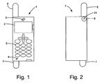
- Fig. 1 discloses a mobile telephone 1 having a man-machine interface for operating the mobile telephone 1 comprising, but not limited to, a display 2, a loudspeaker 3, a microphone 4, and a keypad 5. Furthermore, the mobile telephone 1 has an antenna arrangement comprising a main antenna 6 and a receive antenna 7. The main antenna 6 and/or the receive antenna 7 may be arranged outside of the housing but may as well be provided as internal antennas within the housing of the mobile telephone 1. The antennas 6, 7 are adapted to communicate signals in an over-the-air interface when operated in a wireless communication system.
- Fig. 2 shows the backside of the mobile telephone 1 comprising an external antenna connector 8 according to the invention for connecting an auxiliary antenna to the antenna arrangement of the mobile telephone 1.
- the external antenna connector may be provided at different positions of the casing, such as at the bottom or top end of the casing.
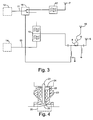
- the external antenna connector 8 is arranged for receiving a coaxial cable antenna connector or terminal 9 operatively connected to an auxiliary antenna 10 by means of a coaxial cable as shown in Fig. 3.
- the auxiliary antenna may be embodied as a car mounted external antenna connectible to the mobile telephone 1 by means of a handsfree kit mounted in the car.
- the auxiliary antenna may be an external antenna for providing an amplified signal in remote areas wherein the signal strength is to weak to be received merely by the main antenna 6 or the receive antenna 7.
- Fig. 3 discloses a first embodiment of the inventive antenna arrangement, comprising an antenna output means 11 operatively connected to a receiver 12, which may be an integrated circuit (IC) of the mobile telephone 1.
- the antenna arrangement also comprises an antenna input 13 means operatively connected to a transmitter (Tx) 14.
- the mobile telephone 1 is adapted for communication in a wideband mode, such as according to the Wideband Call Division Multiple Access (WCDMA) technique used for the Universal Telecommunications Systems (UMTS) standard in the 1900-2170 MHz frequency range.
- WCDMA Wideband Call Division Multiple Access
- UMTS Universal Telecommunications Systems
- the external antenna connector 8 is provided in the signal path between the main antenna 6 and the diplex filter 15.
- the antenna arrangement comprises a switch 16 for selecting the output signal from the antenna arrangement to the receiver 12 from either the receive antenna 7 or the main antenna 6 or possibly the auxiliary antenna 10 if connected.
- the antenna switch 16 is controlled by the insertion of a terminal of the auxiliary antenna 10, as will be described below.
- the switch 16 is operated by a controller, whereby it is possible to provide a diversity antenna arrangement, wherein the strongest of the signals received by the main antenna 6 or the receive antenna 7 is output to the WCDMA receiver 12.
- the receive antenna 7 is optimized for operating at a first frequency band, such as the receive band of the WCDMA operating frequency, which e.g. is 2140-2155 MHz according to the UMTS standard.
- a first frequency band such as the receive band of the WCDMA operating frequency, which e.g. is 2140-2155 MHz according to the UMTS standard.
- the receive antenna 7 may by made relatively small in size.
- the receive antenna 7 may be placed in the lower part of the mobile telephone 1 close to the radio circuitry, which in general is provided on an IC located in this part of the mobile telephone 1. Consequently, the signal does not have to pass a through a long coaxial cable having high losses, as the receive antenna 7 may be directly connected to the IC of a printed circuit board without the intermediation of any coaxial cable.
- BP filter 17 band-pass filter 17 provided in the signal path between the receive antenna 7 and the receiver 12.
- the distance between the main antenna 6 and the receive antenna 7 introduces some RF-isolation as compared to the diplex filter receiver branch. This isolation is generated from the over-the-air path-loss between the two antennas.
- the insertion loss of the separate antenna BP filter 17 is therefore smaller than that of the diplex filter 15.
- Loss budget for the separate receive antenna 7 is in one exemplifying embodiment: BP filter 2.0 dB SPDT switch 0,5 dB Sum 2,5 dB This is a considerable loss improvement of at least 2.5 dB compared to prior art, where no separate receive antenna 7 is provided.
- the receive antenna 7 can be made more efficient compared to when it is a part of the main antenna 6 as it may be constructed as a narrow band antenna. Also, the combined size of the antennas may be reduced.
- Fig. 4 shows an embodiment of the external antenna connector 8 in a cross sectional view in more detail.
- the connector 8 comprises a connector switch 20, such as a conducting leverarm 25, for connecting either the auxiliary antenna 10 or the main antenna 6 to the signal path to the diplex filter.
- the main antenna 6 is automatically disconnected from the diplex filter 15, when the terminal 9 is received in the external antenna connector 8.
- a pin 21 makes contact with the terminal 9 and outputs the signal from the terminal 9 to the receiver 12, or receives signals from the transmitter 14.
- the pin 21 is biased upwards in Fig.4 by means of a spring 22.
- the pin 21 and the spring 22 are received in a cavity 23 enclosing the spring 22.
- a plate or rod 24 connected to the pin 21 retains the pin and the spring 22 in the cavity 23.
- the spring 22 urges the pin 21 towards a first upper position shown in Fig. 4 when no terminal 9 is received in the external antenna connector 8.
- the lever arm 25 is in a first closed position, wherein the connector switch 20 connects the main antenna 6 to the diplex filter 15, and disconnects the auxiliary antenna.
- the pin 21 When the terminal 9 is received in the external antenna connector 8, the pin 21 will be forced downwards by said terminal 9 to a second lower position, wherein the pin 21 forces the lever arm 25 to a second opened position. Consequently, the main antenna 6 will be disconnected from the diplex filter 15 and the external antenna connector 8 and consequently the auxiliary antenna will be connected to said filter 15.
- the pin 21 is made of an electrically conducting material, such as gold, copper, etc. Therefore, the signals from the auxiliary antenna will be forwarded to the leverarm 25, which is also made of such a conducting material for forwarding the signal to the diplex filter 15, to which it is operatively connected.
- the pin 21 acts as a detector for detecting that the terminal 9 of the auxiliary antenna is received in the external antenna connector 8.
- the connector switch 20 together with the DC voltage network described below will provide a control means for automatically controlling the switch 16, as will be described below.
- filter 15 is a diplex filter comprising two band-pass filters, which are adapted to separate the uplink and downlink signals, respectively. Also, the diplex filter 15 provides communication between the receiver 12 and the main antenna 6 or the external antenna connector 8, and between the transmitter 14 and the main antenna 6 or the external antenna connector 8, respectively.
- the main antenna 6 of the antenna arrangement may be optimized for only transmission in a frequency band other than the operating frequency band of the receive antenna, as will be further described below.
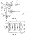
- Fig. 5a illustrates an alternative embodiment of the antenna arrangement according to the invention, wherein a diversity option of the invention is implemented.
- Components that are the same as those of the embodiment of Fig. 3 and Fig. 4 are denoted by the same reference numerals.
- the connector of the diplex filter 15 connected to the switch 16 in the previous embodiment is now connected to a signal strength measurement unit 50.
- the unit 50 comprises a first measurement branch 51 and a second measurement branch 52.
- the first measurement branch 51 is operatively connected to the receive antenna 7, via the band-pass filter 17, and to a baseband switch 30.
- the second measurement branch 52 is operatively connected to the diplex filter 15 and the switch 30.
- Each measurement branch 51, 52 is adapted to measure the signal strength of the received signal, such as the signal-to-noise ratio (S/N) or a Received Signal Strength Indication (RSSI). Then, each measured signal strength is supplied to a controller 53, such as an integrated circuit.
- the controller 53 is adapted to determine which of the signals received by the receive antenna 7 or the main antenna 6 has the highest S/N or signal strength.
- the controller 53 is also connected to the baseband switch 30, which is controlled by the controller 53 based on said determination. When it is determined that either the signal strength of the signal from the main antenna 6 or the receive antenna 7 exceeds the other by a certain amount, the controller 53 can control the switch 30 to select the receiver branch having the best signal condition.
- the controller 53 may be connected to a memory 54, such as a Read Only Memory (ROM) or a Random Access Memory (RAM) capable of storing software code portions as will be explained below.
- ROM Read Only Memory
- RAM Random Access Memory
- the embodiment of Fig. 5a comprises a normally closed switch 56 for detecting when the connector 8 is connected to the auxiliary antenna 10.
- the normally closed switch such as a Hall-element based switch or a reed switch, is adapted to detect e.g. a magnetic field when the mobile telephone 1 is connected to a mating device, which indicates that the auxiliary antenna 10 is received in the connector.
- the detection of the auxiliary antenna 10 will cause the switch 56 to open, thus disconnecting the connection to ground and the switch 30 will be controlled to select the auxiliary antenna.
- Fig. 5b illustrates one embodiment of the implementation of the signal strength measurement unit 50.
- the first measurement branch 51 comprises a Low Noise Amplifier (LNA) 31 operatively connected to the receive antenna 7.
- the output of the LNA 31 is connected to a mixer 32 for down-converting the RF signal to a base-band signal.
- the mixer is therefor connected to an oscillator 33 generating a signal having a suitable frequency.
- the output of the mixer 32 is connected to a chain of amplifiers 34a-e.
- Each amplifier 34a-e is connected to a signal strength indicator means 35 for determining e.g. a RSSI, to be forwarded to the controller 53.
- Each amplifier 34a-34d is connected to the following amplifier, which will further augment the signal.
- the last amplifier 34e of the amplifier chain is connected to the baseband switch 30, which is controlled by the controller 53 to generate a signal at the antenna output 11.
- the second measurement branch corresponds to the first measurement branch and comprises consequently a LNA 36, a mixer 37 connected to the oscillator 33, an amplifier chain 38a-38e, and a signal strength indicator means 39.
- the controller 53 may determine, which of the received signals that should by output at the antenna output based on the RSSI received from each measurement branch 51, 52.
- two receivers are provided.
- the switch 16 is provided after the receivers, which are connected to the receive antenna 7 and the diplex filter 15, respectively.
- the switching is e.g. controlled based on largest signal power, largest signal-to-noise ratio, Maximum Ratio Combining etc.
- the preferred received signal is then forwarded to circuitry within the mobile telephone for further processing.
- said controller 53 may form part of another component of the antenna arrangement, such as the signal strength measurement unit 50.
- the controller may be implemented using a central processing unit (CPU) 55 of the mobile telephone 1.
- the controller 53 may alternatively be connected to the external antenna connector 8.
- the controller 53 When the detector 21 (see Fig. 4) identifies a terminal 9 received in the external antenna connector 8, the controller 53 will receive an auxiliary antenna present notification signal from the external antenna connector 8.
- the notification can be provided by a DC signal switching from a low to a high signal level, or vice versa, (see Fig. 7) at an input terminal of the controller 53.
- a proximity sensor arranged in the external antenna connector 8 may detect the connector of the auxiliary antenna when received therein, and generate a notification signal accordingly.
- the proximity sensor may detect e.g. that an electromagnetic field is present in the connector 8 Then, the controller 53 can control the switch 16 to select the signal received via the external antenna connector 8 of the diversity antenna arrangement, and maintain that signal until the auxiliary antenna is disconnected.
- a device mating the mobile telephone 1, such as a car cradle, can support the mobile telephone in a hands-free mode.
- the mating device can have a magnet for generating a magnetic field provided, which a reed switch or Hall-element based switch within the housing of the mobile telephone can detect the presence of and thus operate the switch 16, possibly via the controller 53 when appropriate.
- the grounding of the DC network at the output side of the connector 8 may in yet an alternative embodiment be provided with an external ground connection instead of via the inductor 81.
- Connecting the mobile telephone 1 to e.g. a mating device, such as the cradle, would provide the grounding of the DC-network.
- Connecting the mobile terminal to the external device would inevitably connect the ground connection, which may be used as an indicator for detecting the terminal 9. This would however require that the polarity of the switching is changed.
- Still another alternative is to use conventional diversity operation without any external antenna, whereby unit 50 determines which of the signals from receive antenna 7 and main antenna 6 is best for reception purpose, such as having largest S/N.
- Fig. 6 illustrates yet another embodiment of the present invention, wherein a multi-mode antenna arrangement is implemented.
- the mobile telephone 1 is adapted for communication not only in a WCDMA mode in a high frequency, but also in at least a second communication mode, such as according to GSM in the 900 MHz range.
- the antenna arrangement of the mobile telephone 1 is adapted for communication in a third mode, such as according to DCS in the 1800 MHz frequency band. Therefore the circuitry of the mobile telephone 1 comprises transmitter and receiver circuitry for the GSM and DCS modes, respectively.
- a first antenna switch 63 which is provided in the signal path between the diplex filter 15 and the main antenna 6.
- the first antenna switch 63 is adapted to switch between the WCDMA mode and the DCS receive mode and DCS transmit mode, since the receiver and the transmitter in DCS communication are not active simultaneously.
- a GSM transmitter 64 and receiver 65 may be connected to a third antenna output means 69a and input means 69b, respectively.
- the GSM transmitter and receiver 64, 65 which may be provided as integrated circuits of the mobile telephone 1, are connected to a second antenna switch 66, which is adapted to switch between GSM transmit mode and GSM receive mode, respectively, since the transmitter and the receiver are not active simultaneously in GSM communication.
- the first and second antenna switch 63, 66 are connected to the controller 53, which is adapted to control the operation of the antenna switches 63, 66 to select the relevant operation mode.
- the controller may be provided as an integrated circuit.
- the controller 53 may be implemented by the CPU 55.
- the antenna switches 63, 66 are also operatively connected to a combine filter 67, which is operatively connected to the external antenna connector 8 and the main antenna 6.
- the combine filter 67 is a combined high pass and low pass filter adapted to pass signals to/from the DCS and WCDMA receiver/transmitter and to/from the GSM receiver/transmitter, respectively.
- the main antenna 6 transmits signals only in the WCDMA transmit frequency band, while it transmits and receives signals in the DCS and GSM frequency bands. Therefore, the bandwidth requirement of the main antenna 6 may be optimized for the GSM uplink and downlink frequency bands of 890-915 MHz and 935-960 MHz, the DCS uplink and downlink frequency bands of 1710-1785 MHz and 1805-1880 MHz, and the WCDMA uplink frequency band of 1920-1980 MHz. Consequently, it is required that the bandwidth of the upper frequency band of the main antenna 6 is only 270 MHz, whereas an antenna covering all frequency ranges, such that has to be provided when diversity reception is facilitated, has to have an upper bandwidth of 460 MHz.
- the auxiliary antenna 10 may still be adapted to provide both WCDMA transmission and reception in combination with DCS and GSM communication, i.e. an all-bands antenna covering the appropriate operating frequency ranges of the mobile telephone 1. Therefore, the switch 16 is either automatically operated by the connector switch 20, or by the controller 53 to select the auxiliary antenna 10 when the WCDMA mode is selected.
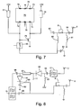
- Fig. 7 is a block diagram of an embodiment of a switch 70 for selecting the signal from either the receive antenna 7 or the main antenna 6/external antenna connector 8 according to the invention, and components involved for controlling the switch 16.
- the switch 16 may be implemented as a Single Pole Double Throw (SPDT) semiconductor switch, which is operated from a DC source.
- SPDT switches may utilize PIN-diodes, GaAs FETs (Field Effect Transistors), JFETs (Junction Field Effect Transistors) or MEMS (Microelectromechanical Systems) technology.
- the switch 70 comprises six terminals; two control terminals 71, 72, two output terminals 73, 74, one input terminal 75, and one ground terminal 76.
- Each of the control terminals 71, 72 are connected to a +3V DC voltage via a first and a second resistor 77, 78. Further, the first control terminal 71 is connected to an inverting transistor 79.
- the inverting transistor is chosen as a BJT transistor, which is commercially available from Philips Semiconductors, the Netherlands, having part number BC817.
- the inverting transistor may also be implemented using other transistors, such as a MOS transistor.
- the collector of the transistor 79 is connected to the first control terminal 71 and consequently to +3V DC via the second resistor 78.
- the emitter of the transistor is connected to ground.
- the base of the transmitter 79 is connected to the second control terminal 72, and consequently to +3V DC via the first resistor 77.
- the second control terminal 72 is connected to the output terminal of the antenna connector 8, more precisely to the connection point between the external antenna connector 8 and the diplex filter 15, via a first AC blocking inductor 80.
- the connection point between the external antenna connector 8 and the main antenna 6 is referenced to ground via a second AC blocking inductor 81.
- the second input terminal 72 of the SPDT switch 70 is connected to ground via a first capacitor 82.
- DC blocking capacitors 83, 84 are provided between the the external antenna connector 8 and the RF front end components, such as the diplex filter 15 and the combine filter 67, as well as between the main antenna 6 external antenna connector 8.
- the sizes of the components are: first and second resistors 22 k ⁇ ; first and second inductor 56 nH; first capacitor and DC blocking capacitors 33 pF.
- the output terminals 73, 74 of the SPDT switch 70 are connected to the diplex filter 15 and the receive antenna 7, respectively, and the input terminal 75 is connected to the input terminal of the WCDMA receiver 12.
- the DC network described above will automatically control the SPDT switch 70.
- the connector switch 20 of external connector 8 When the connector switch 20 of external connector 8 is in its first closed position, i.e. no connector of an auxiliary antenna is received in the external connector 8, the DC network will have a ground reference via the second inductor 81. Therefore, the input signal at the first control terminal 71 of the SPDT switch 70 will be high, and the signal at the second control terminal 72 will be low. Therefore, the SPDT switch 70 selects its second output terminal 74 to be connected to its input terminal 75, i.e. the receive antenna 7 will be connected to the WCDMA receiver 12.
- the pin 21 will open the connector switch 20, wherein the DC connection to ground via the second inductor 81 will be disconnected. Consequently, the input signal at the first control terminal 71 of the SPDT switch 70 will be low and the input signal at its second control terminal 72 will be high. Therefore, the SPDT switch 70 is controlled to select its first output terminal 73 to be connected to its input terminal 75, i.e. diplex filter 15 will be connected to the WCDMA receiver 12.
- the controller 53 is adapted to control the SPDT switch 70. Therefore, the control terminals 71, 72 of the SPDT switch 70 are connected to the controller 53. Also, the controller 53 is connected to the DC network illustrated in Fig. 7, and is adapted to determine whether the connector switch 20 is open or closed and control the switch 70 accordingly. Alternatively, the controller 53 controls the switch 16, 70 independently of the connector 8, or receives an connector present notification signal from an electronic detection means of the controller.
- a controllable series switch 85 connected to the controller 53 is provided in the signal path between the control terminal 72 and the AC blocking inductor 80.
- the series switch 85 is e.g. provided as a series transistor.
- the controller can thus select either the main antenna 6/the auxiliary antenna 10 or the receive antenna 7.
- the series switch 85 is not necessary when the diversity option is not utilized. In such a case (not shown), the control terminal 72 is directly connected to said inductor 80.
- Fig. 8 discloses one embodiment for implementing the switch 16 with discrete components.
- a first PIN diode 90 is connected with its anode to a DC blocking capacitor 91, which is connected to the band pass filter 17, and to +3V DC via a first AC blocking inductor 92.
- the cathode of the first diode 90 is connected to the antenna output 11 of the antenna arrangement and to one end of a quarter wave microstrip 93.
- the microstrip 93 which may be implemented with a printed patch on an integrated circuit, is short-circuited for high frequency signals when biased by a DC voltage and conducting otherwise.
- Fig. 8 discloses one embodiment for implementing the switch 16 with discrete components.
- the microstrip 93 is short-circuited for signals in the 2 GHz frequency range when biased, and may be implemented with an approximately 2 cm long patch. However, other frequencies are also possible, wherein the length of the patch is varied.
- the microstrip 93 is at its other end connected to a DC blocking capacitor 94, which is connected to the diplex filter 15, and to the anode of a second PIN diode 95.
- the cathode of the second diode 95 is connected to the previously described (see Fig. 7) capacitor 82 and AC blocking inductor 80.
- the sizes of the components of Fig. 8 are: inductors 56 nH, capacitors 33 pF. Any commercially available diode, such as the PIN diode having model number BAR 14 from Infineon Technologies AG, Germany, may be used as the diode 90, 94.
- the switch implemented according to Fig. 8 will connect the receive antenna 7 to the antenna output 11 when the connector switch 20 is in its closed position, whereby the microstrip 93 will be biased by the DC voltage.
- the switch arrangement of Fig. 8 will select the external antenna connector 8 to the antenna output 11.
- the need of an SPDT switch is unnecessary.
- Two separate Low Noise Amplifiers (LNA) of the WCDMA receiver is connected to the receive antenna 7 and the diplex filter 15, respectively.
- Each of the LNA is operated by applying a voltage when either the receive antenna 7 or the diplex filter 15 should be connected to the receiver.
- the LNAs are typically integrated in an IC together with the other components of the WCDMA receiver 12.
- the switching can be provided with switching means after the LNAs within the IC comprising the WCDMA receiver.
- Fig. 9 illustrates a first method for controlling the receive mode of the antenna arrangement, wherein diversity receive is not provided.
- the procedure for controlling the switch starts in a first step 200, such as when the mobile telephone 1 is switched on or set to a mode, in which communication is enabled.
- a second step 201 it is determined whether the external antenna connector 8 is in electrical or operative connection with an auxiliary antenna, e.g. by detecting whether an antenna connector is received in the external antenna connector 8. If yes, the procedure continuous in step 202, wherein the switch 16, 70 selects the signal from the auxiliary antenna, i.e. the WCDMA receiver 12 is operatively connected to the external antenna connector 8.
- step 201 the procedure continuous in step 203, wherein the signal from the receive antenna 7 is selected by the switch 16, 70, i.e. the WCDMA receiver 12 is operatively connected to the receive antenna 7.
- the procedure proceeds to step 204 from step 202 or step 203, wherein it is determined whether the communication apparatus is set to a mode, wherein communication is no longer enabled although the communication apparatus is switched on. If the answer in step 204 is affirmative, the procedure proceeds in step 205, wherein the procedure is ended. However, if the answer in step 204 is negative the procedure continuous in step 201. The procedure may be repeated until the mobile terminal is set to a communication disabled mode or switched off, whereby the procedure is completely abandoned.
- Fig. 10 illustrates an alternative method for controlling the receive mode of the antenna arrangement, wherein diversity reception is provided.
- the procedure for controlling the switch starts in a first step 300, such as when the mobile telephone 1 is switched on and/or switched to a communication enabled mode.
- a second step 301 it is determined whether the external antenna connector 8 is in electrical or operative connection with an external antenna, such as by detecting whether an antenna connector is received in the external antenna connector 8. If so, the procedure continuous in step 302, wherein the switch 16, 70 selects the signal from the auxiliary antenna, i.e. antenna output 11 is operatively connected to the external antenna connector 8.
- step 301 the procedure continuous in step 303, wherein it is determined whether the signal from the main antenna 6 is stronger than the signal from the receive antenna 7. If so, in step 304 the switch 16, 70 is controlled to connect the antenna output 11 to the main antenna 6. However, if the answer in step 303 is no, in step 305 the switch 16, 70 selects the signal from the receive antenna 7, i.e. the antenna output 11 is operatively connected to the receive antenna 7. From step 302, 304 and 305, the procedure proceeds to step 306, wherein it may be determined whether the communication apparatus is set to a communication disabled mode as described above. If the answer in step 306 is affirmative, the procedure proceeds in step 307, wherein the procedure is ended. However, if the answer in step 306 is negative the procedure continuous in step 301. The procedure may then be repeated until the mobile terminal is switched off or set to a communication disabled mode.
- the controller 53 may execute the procedures illustrated with reference to Figs. 8 and 9.
- the controller 53 receives information from the external antenna connector 8, and optionally from the signal strength measurement unit 50, and controls the switch 16 accordingly.
- the procedure may be provided by a software product comprising software code portions for performing the steps according to the invention when said product is run by e.g. the controller 53 of the mobile telephone 1. Therefore, the controller 53 should have digital computer capabilities.
- the software may be load into the memory 54 of the mobile telephone 1, to which the controller 53 has access, or into a register of the controller 53 containing appropriate control algorithms therein.
- the present invention has been described above in relation to a mobile telephone 1.
- the invention is not limited to a mobile telephone 1, but can be included in any portable radio communication apparatus, such as a mobile radio terminal, a pager, or a communicator, i.e. an electronic organizer, a smartphone or the like.
- the present invention has been described in relation to connecting the main antenna or the receive antenna to a WCDMA receiver.
- the invention is not limited to a WCDMA technology.
Landscapes
- Engineering & Computer Science (AREA)
- Computer Networks & Wireless Communication (AREA)
- Remote Sensing (AREA)
- Signal Processing (AREA)
- Transceivers (AREA)
- Burglar Alarm Systems (AREA)
- Input Circuits Of Receivers And Coupling Of Receivers And Audio Equipment (AREA)
Claims (14)
- Système d'antenne pour appareil de communication portatif, comprenant :une antenne principale (6) pouvant être connectée à un moyen d'entrée d'antenne (13) ;une antenne de réception (7) pouvant être connectée à un moyen de sortie d'antenne (11) ;un connecteur d'antenne externe (8) pour recevoir une borne (9) d'une antenne auxiliaire (10) ;un détecteur d'antenne (21, 56) agencé pour détecter la borne (9) lorsqu'elle est connectée audit connecteur d'antenne externe (8) ;caractérisé par :un filtre commun (15) ayant des premier, second et troisième accès pour séparer des signaux fournis au moyen de sortie d'antenne (11) et des signaux provenant du moyen d'entrée d'antenne (13) ; etun moyen de commutation (16, 30, 70) conçu pour connecter soit ladite antenne de réception, soit ledit premier accès audit moyen de sortie d'antenne, dans lequel les moyens d'entrée d'antenne sont fonctionnellement connectés audit second accès, etdans lequel ledit troisième accès peut être connecté soit à l'antenne principale (6), soit au connecteur d'antenne externe (8), de façon que le moyen d'entrée d'antenne (13) puisse être électriquement ou fonctionnellement connecté au connecteur d'antenne externe (8) ou à l'antenne principale (6) ; etun réseau à tension continue, qui est connecté au moyen de commutation et au détecteur d'antenne (21, 56), et qui est agencé pour commander automatiquement le moyen de commutation afin de connecter le connecteur d'antenne externe (8) au moyen de sortie d'antenne (11) et pour déconnecter l'antenne de réception (7) du moyen de sortie d'antenne (11) lorsque la borne (9) est connectée au connecteur d'antenne externe (8), dans lequel l'antenne principale (6) est automatiquement déconnectée du moyen d'entrée d'antenne par un commutateur de connecteur (20) lorsque la borne (9) est connectée au connecteur d'antenne externe (8).
- Système d'antenne selon la revendication 1, dans lequel l'antenne de réception (7) est optimisée pour ne recevoir que des signaux se situant dans une première bande de fréquences, et dans lequel l'antenne principale (6) est optimisée pour n'émettre que dans une seconde bande de fréquences.
- Système d'antenne selon la revendication 2, dans lequel les première et seconde bandes de fréquences appartiennent toutes deux à un premier système de télécommunication.
- Système d'antenne selon la revendication 2 ou 3, dans lequel l'antenne principale (6) est en outre optimisée pour la réception et l'émission dans un second et/ou un troisième système de télécommunication.
- Système d'antenne selon l'une quelconque des revendications 2-4, dans lequel l'antenne de réception (7) est une antenne à réception seule de type WCDMA (Accès Multiple par Répartition de Code à Large Bande).
- Système d'antenne selon l'une quelconque des revendications 4 ou 5, dans lequel l'antenne principale (6) est optimisée pour l'émission dans une bande de fréquences WCDMA, et pour la réception et l'émission dans une bande de fréquences GSM (Système Mondial de Communications Mobiles) et/ou DCS (Système de Communication Numérique).
- Système d'antenne selon l'une quelconque des revendications précédentes, dans lequel le connecteur d'antenne externe (8) est disposé dans un trajet de signal entre l'antenne principale (6) et le moyen de sortie d'antenne (11).
- Antenne selon l'une quelconque des revendications précédentes, dans laquelle le moyen de commutation (16, 30, 70) est disposé dans le trajet de signal entre le connecteur d'antenne externe (8) et le moyen de sortie d'antenne (11) et dans le trajet de signal entre l'antenne de réception (7) et le moyen de sortie d'antenne (11).
- Système d'antenne selon l'une quelconque des revendications précédentes, dans lequel le détecteur d'antenne (21) et le moyen de commutation (16, 30, 70) sont fonctionnellement connectés, et le détecteur (21) est conçu pour faire fonctionner le commutateur de connecteur (20) disposé dans le connecteur d'antenne externe (8), ledit commutateur de connecteur (20) en association avec le réseau à tension continue formant un moyen de commande qui est conçu pour commander automatiquement le commutateur (16, 30, 70).
- Système d'antenne selon l'une quelconque des revendications 3-8, dans lequel le connecteur d'antenne externe (8) est connecté au réseau à tension continue, qui est agencé pour régler le moyen de commutation (16, 30, 70) à un premier mode lorsque le détecteur (21) est à une première position, le commutateur de connecteur (20) du connecteur d'antenne externe (8) à une première position étant fonctionnellement relié à l'antenne principale (6) et séparé du connecteur d'antenne externe (8), et pour régler le moyen de commutation (16, 30, 70) à un second mode lorsque le détecteur (21) est à une seconde position, le détecteur (21) positionnant le commutateur de connecteur (20) à une seconde position pour le séparer de l'antenne principale (6) et le relier au connecteur d'antenne (8).
- Système d'antenne selon la revendication 1, dans lequel le détecteur est une broche élastique (21) disposée dans une cavité (23) du connecteur d'antenne externe (8), la broche (21) est à une première position lorsque la borne (9) est reçue dans le connecteur d'antenne externe (8), et disposée de façon à être contrainte de passer à une seconde position par la borne (9) lorsqu'elle est reçue dans le connecteur d'antenne externe (8).
- Système d'antenne selon l'une quelconque des revendications précédentes, comprenant en outre des premier et second moyens de commutation d'antenne (63, 66) pour commuter entre différents modes de fonctionnement du système d'antenne, le premier moyen de commutation d'antenne (63) étant connecté à un filtre diplexeur (15) et à un filtre de combinaison (67), et étant agencé pour laisser passer des signaux vers le moyen de sortie d'antenne (11) et en provenance du moyen d'entrée d'antenne (13), ou vers ou depuis l'un ou l'autre d'un second moyen de sortie d'antenne (68a) et d'un second moyen d'entrée d'antenne (68b) ; le second commutateur d'antenne (66) étant connecté au filtre de combinaison (67), et étant agencé pour laisser passer des signaux provenant de l'antenne principale (6) ou du connecteur d'antenne externe (8) vers un troisième moyen de sortie d'antenne (69a) ou en provenance d'un troisième moyen d'entrée d'antenne (69b) ; le premier moyen de commutation d'antenne (63) étant conçu pour effectuer une commutation entre un mode d'antenne à large bande et des états de réception ou d'émission d'un second mode de fonctionnement, et le second moyen de commutation d'antenne (66) étant conçu pour effectuer une commutation entre des états de réception et d'émission d'un troisième mode de fonctionnement.
- Terminal radio mobile comprenant le système d'antenne selon l'une quelconque des revendications précédentes.
- Terminal radio mobile selon la revendication 13, dans lequel le terminal radio mobile est un téléphone mobile (1).
Priority Applications (6)
| Application Number | Priority Date | Filing Date | Title |
|---|---|---|---|
| DE60305637T DE60305637T2 (de) | 2003-03-19 | 2003-03-19 | Schaltbare Antennenanordnung |
| AT03006033T ATE328400T1 (de) | 2003-03-19 | 2003-03-19 | Schaltbare antennenanordnung |
| EP03006033A EP1460771B1 (fr) | 2003-03-19 | 2003-03-19 | Arrangement d'antennes commutable |
| PCT/EP2004/002088 WO2004084427A1 (fr) | 2003-03-19 | 2004-03-02 | Antenne commutable |
| US10/549,054 US7511681B2 (en) | 2003-03-19 | 2004-03-02 | Switchable antenna arrangement |
| CN2004800136862A CN1792041B (zh) | 2003-03-19 | 2004-03-02 | 天线装置及其接收模式的控制方法和移动无线电终端 |
Applications Claiming Priority (1)
| Application Number | Priority Date | Filing Date | Title |
|---|---|---|---|
| EP03006033A EP1460771B1 (fr) | 2003-03-19 | 2003-03-19 | Arrangement d'antennes commutable |
Publications (2)
| Publication Number | Publication Date |
|---|---|
| EP1460771A1 EP1460771A1 (fr) | 2004-09-22 |
| EP1460771B1 true EP1460771B1 (fr) | 2006-05-31 |
Family
ID=32798822
Family Applications (1)
| Application Number | Title | Priority Date | Filing Date |
|---|---|---|---|
| EP03006033A Expired - Lifetime EP1460771B1 (fr) | 2003-03-19 | 2003-03-19 | Arrangement d'antennes commutable |
Country Status (5)
| Country | Link |
|---|---|
| US (1) | US7511681B2 (fr) |
| EP (1) | EP1460771B1 (fr) |
| CN (1) | CN1792041B (fr) |
| AT (1) | ATE328400T1 (fr) |
| DE (1) | DE60305637T2 (fr) |
Families Citing this family (48)
| Publication number | Priority date | Publication date | Assignee | Title |
|---|---|---|---|---|
| US7072616B2 (en) * | 2002-09-09 | 2006-07-04 | Conexant Systems, Inc. | Multi-protocol interchip interface |
| KR20150040371A (ko) | 2002-10-22 | 2015-04-14 | 제이슨 에이. 설리반 | 프로세서를 수용하도록 구성된 장치의 비힌지식 용기 및 이를 포함하는 가전 기기 |
| WO2004038555A2 (fr) | 2002-10-22 | 2004-05-06 | Isys Technologies | Ordinateur robuste et personnalisable |
| EP1557075A4 (fr) | 2002-10-22 | 2010-01-13 | Sullivan Jason | Module de controle non associe aux peripheriques possedant des proprietes ameliorees de dissipation de chaleur |
| US7557433B2 (en) * | 2004-10-25 | 2009-07-07 | Mccain Joseph H | Microelectronic device with integrated energy source |
| JP4505274B2 (ja) * | 2004-06-30 | 2010-07-21 | オリンパス株式会社 | 受信システム |
| US7359677B2 (en) * | 2005-06-10 | 2008-04-15 | Sige Semiconductor Inc. | Device and methods for high isolation and interference suppression switch-filter |
| DE102005040604B4 (de) * | 2005-08-23 | 2009-02-26 | Siemens Ag | Verfahren zum Umschalten von einer ersten Antenne eines Funkmoduls auf eine zweite Antenne des Funkmoduls |
| KR100842576B1 (ko) * | 2005-09-08 | 2008-07-01 | 삼성전자주식회사 | 휴대 단말기의 안테나 장치 |
| US7587177B1 (en) * | 2005-12-12 | 2009-09-08 | Exalt, Inc. | Electronically configurable transmit and receive paths for FDD wireless communication devices |
| TWI292257B (en) * | 2006-03-09 | 2008-01-01 | Wistron Corp | Wireless communication module capable of switching an internal antenna module and an external antenna module |
| US20080039160A1 (en) * | 2006-07-21 | 2008-02-14 | Homer Steven S | Wireless communications interface for a portable electronic device |
| ES2601803T3 (es) * | 2006-11-17 | 2017-02-16 | Nokia Technologies Oy | Aparato para permitir a dos elementos compartir una alimentación común |
| US8350761B2 (en) | 2007-01-04 | 2013-01-08 | Apple Inc. | Antennas for handheld electronic devices |
| US7595759B2 (en) * | 2007-01-04 | 2009-09-29 | Apple Inc. | Handheld electronic devices with isolated antennas |
| KR20080064470A (ko) * | 2007-01-05 | 2008-07-09 | 삼성전자주식회사 | 안테나 조립체 및 이를 갖는 정보처리장치 |
| JP4869972B2 (ja) * | 2007-02-14 | 2012-02-08 | 株式会社エヌ・ティ・ティ・ドコモ | ユーザ装置、送信方法、及び無線通信システム |
| US7973725B2 (en) * | 2008-02-29 | 2011-07-05 | Research In Motion Limited | Mobile wireless communications device with selective load switching for antennas and related methods |
| EP2099092A1 (fr) * | 2008-03-04 | 2009-09-09 | Bury Sp.z.o.o | Procédé de transmission d'un signal de positionnement par satellite à partir d'une antenne externe vers un récepteur non exposé, en particulier dans des véhicules mécaniques et dispositif adapté pour utiliser ce procédé |
| US8106836B2 (en) | 2008-04-11 | 2012-01-31 | Apple Inc. | Hybrid antennas for electronic devices |
| TWI396394B (zh) | 2008-06-13 | 2013-05-11 | Asustek Comp Inc | 多頻段行動通訊裝置 |
| KR101435492B1 (ko) * | 2008-10-30 | 2014-08-28 | 삼성전자주식회사 | 휴대용 무선 단말기의 안테나 장치 |
| KR20110029647A (ko) * | 2009-09-16 | 2011-03-23 | 삼성전자주식회사 | 휴대용 단말기의 다중 대역 내장형 안테나 장치 |
| US8611356B2 (en) * | 2009-11-13 | 2013-12-17 | Exalt Communications Incorporated | Apparatus for ethernet traffic aggregation of radio links |
| KR101687632B1 (ko) * | 2010-05-10 | 2016-12-20 | 삼성전자주식회사 | 휴대용 단말기의 가변형 내장 안테나 장치 |
| US8412291B2 (en) * | 2010-05-19 | 2013-04-02 | Microsoft Corporation | Detection, selection and provision of external antennas for a mobile device |
| WO2012109393A1 (fr) | 2011-02-08 | 2012-08-16 | Henry Cooper | Antenne en cornet à pas en fréquence à gain élevé |
| WO2012109498A1 (fr) | 2011-02-09 | 2012-08-16 | Henry Cooper | Antenne ondulée en cornet à plage de fréquences améliorée |
| CN103164383A (zh) * | 2011-12-08 | 2013-06-19 | 华硕电脑股份有限公司 | 电子系统及其第二电子装置 |
| US8798554B2 (en) * | 2012-02-08 | 2014-08-05 | Apple Inc. | Tunable antenna system with multiple feeds |
| TWI525896B (zh) * | 2012-02-24 | 2016-03-11 | 仁寶電腦工業股份有限公司 | 天線模組與電子裝置 |
| CN103384962B (zh) * | 2012-03-05 | 2015-06-10 | 华为终端有限公司 | 天线切换电路和无线终端设备 |
| US8760360B2 (en) * | 2012-03-16 | 2014-06-24 | Amazon Technologies, Inc. | Switching multi-mode antenna |
| US9257737B2 (en) * | 2012-04-27 | 2016-02-09 | Getac Technology Corporation | Antenna switching circuit and electronic device and antenna switching method thereof |
| US8892160B2 (en) * | 2012-05-18 | 2014-11-18 | Cellco Partnership | Automatic detection of mobile phone antennas |
| WO2014011943A1 (fr) * | 2012-07-11 | 2014-01-16 | Wireless Research Development | Antenne de boîtier orientable électronique améliorant des performances employant un couplage direct ou sans fil |
| US8933858B2 (en) * | 2012-08-09 | 2015-01-13 | Qualcomm Incorporated | Front end parallel resonant switch |
| US9450309B2 (en) | 2013-05-30 | 2016-09-20 | Xi3 | Lobe antenna |
| US10128884B2 (en) | 2014-02-19 | 2018-11-13 | Huawei Device (Shenzhen) Co., Ltd. | Antenna interface circuit, data card, and antenna connection control method and apparatus |
| TWI561015B (en) | 2014-10-28 | 2016-12-01 | Realtek Semiconductor Corp | Front-end circuit of wireless communication system and wireless communication system |
| CN105634531B (zh) * | 2014-10-30 | 2018-09-04 | 瑞昱半导体股份有限公司 | 无线通信系统的前端电路以及无线通信系统 |
| US9614949B2 (en) * | 2015-03-20 | 2017-04-04 | Motorola Mobility Llc | WIFI connectivity in a modular portable cellular device |
| CN106160771A (zh) * | 2015-03-31 | 2016-11-23 | 联想(北京)有限公司 | 一种电子设备及其工作方法 |
| US9673916B2 (en) | 2015-04-17 | 2017-06-06 | Apple Inc. | Electronic device with over-the-air wireless self-testing capabilities |
| KR102511051B1 (ko) | 2015-12-10 | 2023-03-16 | 삼성전자주식회사 | 안테나를 포함하는 전자 장치 |
| CN105635387B (zh) * | 2016-01-06 | 2019-02-05 | Oppo广东移动通信有限公司 | 一种天线控制方法及移动终端 |
| CN107612583A (zh) * | 2017-10-19 | 2018-01-19 | 环鸿电子(昆山)有限公司 | 可切换外接天线的天线系统及控制方法 |
| CN112886976B (zh) * | 2020-12-31 | 2022-07-19 | 海能达通信股份有限公司 | 一种天线共享电路及终端 |
Family Cites Families (13)
| Publication number | Priority date | Publication date | Assignee | Title |
|---|---|---|---|---|
| FI90703C (fi) * | 1992-02-14 | 1994-03-10 | Nokia Mobile Phones Ltd | Diversiteettiboosteri |
| US5649306A (en) * | 1994-09-16 | 1997-07-15 | Motorola, Inc. | Portable radio housing incorporating diversity antenna structure |
| JP3382764B2 (ja) * | 1995-10-27 | 2003-03-04 | 松下電器産業株式会社 | 無線移動機 |
| TW317067B (en) * | 1997-01-23 | 1997-10-01 | Acer Peripherals Inc | Antenna switching device used in radio handheld set |
| EP0905915A3 (fr) * | 1997-09-29 | 2002-11-27 | Matsushita Electric Industrial Co., Ltd. | Adaptateur externe pour un télephone cellulaire portable |
| EP0924810B1 (fr) * | 1997-12-22 | 2004-04-07 | The Whitaker Corporation | Connecteur d' antenne coaxiale pour un téléphone portable |
| WO2002001741A1 (fr) * | 2000-06-26 | 2002-01-03 | Matsushita Electric Industrial Co., Ltd. | Circuit de repartition a trois frequences, circuit de repartition et dispositif de communication radio |
| US7394430B2 (en) * | 2001-04-11 | 2008-07-01 | Kyocera Wireless Corp. | Wireless device reconfigurable radiation desensitivity bracket systems and methods |
| US6690251B2 (en) * | 2001-04-11 | 2004-02-10 | Kyocera Wireless Corporation | Tunable ferro-electric filter |
| US7180467B2 (en) * | 2002-02-12 | 2007-02-20 | Kyocera Wireless Corp. | System and method for dual-band antenna matching |
| US6781544B2 (en) * | 2002-03-04 | 2004-08-24 | Cisco Technology, Inc. | Diversity antenna for UNII access point |
| KR100498936B1 (ko) * | 2002-11-15 | 2005-07-04 | 삼성전자주식회사 | 휴대용 무선 단말기의 다이버시티 안테나 장치 |
| DE602004011774T2 (de) * | 2003-07-08 | 2009-02-05 | Matsushita Electric Industrial Co., Ltd., Kadoma-shi | Tragbares funkgerät |
-
2003
- 2003-03-19 DE DE60305637T patent/DE60305637T2/de not_active Expired - Lifetime
- 2003-03-19 EP EP03006033A patent/EP1460771B1/fr not_active Expired - Lifetime
- 2003-03-19 AT AT03006033T patent/ATE328400T1/de not_active IP Right Cessation
-
2004
- 2004-03-02 CN CN2004800136862A patent/CN1792041B/zh not_active Expired - Fee Related
- 2004-03-02 US US10/549,054 patent/US7511681B2/en not_active Expired - Fee Related
Also Published As
| Publication number | Publication date |
|---|---|
| US7511681B2 (en) | 2009-03-31 |
| EP1460771A1 (fr) | 2004-09-22 |
| CN1792041A (zh) | 2006-06-21 |
| CN1792041B (zh) | 2010-12-08 |
| US20070018895A1 (en) | 2007-01-25 |
| DE60305637T2 (de) | 2007-05-03 |
| DE60305637D1 (de) | 2006-07-06 |
| ATE328400T1 (de) | 2006-06-15 |
Similar Documents
| Publication | Publication Date | Title |
|---|---|---|
| EP1460771B1 (fr) | Arrangement d'antennes commutable | |
| AU724641B2 (en) | Dual-band antenna coupler for a portable radiotelephone | |
| US6510310B1 (en) | Dual mode phone architecture utilizing a single transmit-receive switch | |
| US6154177A (en) | Antenna device and radio receiver using the same | |
| US8467738B2 (en) | Multi-mode radio frequency front end module | |
| US7197284B2 (en) | Antenna switches including field effect transistors | |
| CN1929198B (zh) | 天线装置和无线电通信终端 | |
| KR100995799B1 (ko) | 디지털 방식으로 제어되는 안테나 동조 회로부를 갖는 fm수신기 | |
| KR101016120B1 (ko) | 멀티밴드 무선 통신 방법 및 멀티밴드 무선 통신 장치 | |
| US20060009164A1 (en) | Radio frequency switching circuit | |
| US20030181192A1 (en) | Apparatus and method for branching signal for mobile terminal | |
| WO2004084427A1 (fr) | Antenne commutable | |
| US20060140573A1 (en) | Apparatus for detecting output power in dual-mode portable wireless terminal | |
| US20160126640A1 (en) | Diversity antenna apparatus of mobile terminal and implementation method thereof | |
| EP1739857A2 (fr) | Système de commutation d'antenne | |
| EP2134000B1 (fr) | Dispositif de communication mobile multi-bande | |
| EP1131898B1 (fr) | Telephone cellulaire, couvercle rabattable, et articulation | |
| KR100669484B1 (ko) | 무선파를 송수신하기 위한 안테나 장치 및 방법, 그리고 이를 이용한 무선통신장치 | |
| US7505743B2 (en) | Dual band transmitter having filtering coupler | |
| CN108258384B (zh) | 电子装置、天线组件及改善天线辐射指标的方法 | |
| US7228110B2 (en) | Low cost high frequency device having compact mounting area, high frequency amplification method, wireless communication device and mobile telephone including low cost and high frequency circuit having compact mounting area | |
| WO1995013668A1 (fr) | Systeme de commutation d'antenne electronique | |
| KR100622235B1 (ko) | 핀 다이오드를 이용한 무선 통신 장치의 임피던스 정합방법 및 이를 위한 임피던스 정합 장치 | |
| KR100318916B1 (ko) | 다중밴드 단말기의 전력 증폭 장치 | |
| US20240014845A1 (en) | Radio-frequency circuit |
Legal Events
| Date | Code | Title | Description |
|---|---|---|---|
| PUAI | Public reference made under article 153(3) epc to a published international application that has entered the european phase |
Free format text: ORIGINAL CODE: 0009012 |
|
| AK | Designated contracting states |
Kind code of ref document: A1 Designated state(s): AT BE BG CH CY CZ DE DK EE ES FI FR GB GR HU IE IT LI LU MC NL PT RO SE SI SK TR |
|
| AX | Request for extension of the european patent |
Extension state: AL LT LV MK |
|
| 17P | Request for examination filed |
Effective date: 20050322 |
|
| AKX | Designation fees paid |
Designated state(s): AT BE BG CH CY CZ DE DK EE ES FI FR GB GR HU IE IT LI LU MC NL PT RO SE SI SK TR |
|
| 17Q | First examination report despatched |
Effective date: 20050704 |
|
| GRAP | Despatch of communication of intention to grant a patent |
Free format text: ORIGINAL CODE: EPIDOSNIGR1 |
|
| GRAS | Grant fee paid |
Free format text: ORIGINAL CODE: EPIDOSNIGR3 |
|
| GRAA | (expected) grant |
Free format text: ORIGINAL CODE: 0009210 |
|
| AK | Designated contracting states |
Kind code of ref document: B1 Designated state(s): AT BE BG CH CY CZ DE DK EE ES FI FR GB GR HU IE IT LI LU MC NL PT RO SE SI SK TR |
|
| PG25 | Lapsed in a contracting state [announced via postgrant information from national office to epo] |
Ref country code: SI Free format text: LAPSE BECAUSE OF FAILURE TO SUBMIT A TRANSLATION OF THE DESCRIPTION OR TO PAY THE FEE WITHIN THE PRESCRIBED TIME-LIMIT Effective date: 20060531 Ref country code: LI Free format text: LAPSE BECAUSE OF FAILURE TO SUBMIT A TRANSLATION OF THE DESCRIPTION OR TO PAY THE FEE WITHIN THE PRESCRIBED TIME-LIMIT Effective date: 20060531 Ref country code: FI Free format text: LAPSE BECAUSE OF FAILURE TO SUBMIT A TRANSLATION OF THE DESCRIPTION OR TO PAY THE FEE WITHIN THE PRESCRIBED TIME-LIMIT Effective date: 20060531 Ref country code: IT Free format text: LAPSE BECAUSE OF FAILURE TO SUBMIT A TRANSLATION OF THE DESCRIPTION OR TO PAY THE FEE WITHIN THE PRESCRIBED TIME-LIMIT;WARNING: LAPSES OF ITALIAN PATENTS WITH EFFECTIVE DATE BEFORE 2007 MAY HAVE OCCURRED AT ANY TIME BEFORE 2007. THE CORRECT EFFECTIVE DATE MAY BE DIFFERENT FROM THE ONE RECORDED. Effective date: 20060531 Ref country code: NL Free format text: LAPSE BECAUSE OF FAILURE TO SUBMIT A TRANSLATION OF THE DESCRIPTION OR TO PAY THE FEE WITHIN THE PRESCRIBED TIME-LIMIT Effective date: 20060531 Ref country code: BE Free format text: LAPSE BECAUSE OF FAILURE TO SUBMIT A TRANSLATION OF THE DESCRIPTION OR TO PAY THE FEE WITHIN THE PRESCRIBED TIME-LIMIT Effective date: 20060531 Ref country code: CZ Free format text: LAPSE BECAUSE OF FAILURE TO SUBMIT A TRANSLATION OF THE DESCRIPTION OR TO PAY THE FEE WITHIN THE PRESCRIBED TIME-LIMIT Effective date: 20060531 Ref country code: AT Free format text: LAPSE BECAUSE OF FAILURE TO SUBMIT A TRANSLATION OF THE DESCRIPTION OR TO PAY THE FEE WITHIN THE PRESCRIBED TIME-LIMIT Effective date: 20060531 Ref country code: RO Free format text: LAPSE BECAUSE OF FAILURE TO SUBMIT A TRANSLATION OF THE DESCRIPTION OR TO PAY THE FEE WITHIN THE PRESCRIBED TIME-LIMIT Effective date: 20060531 Ref country code: CH Free format text: LAPSE BECAUSE OF FAILURE TO SUBMIT A TRANSLATION OF THE DESCRIPTION OR TO PAY THE FEE WITHIN THE PRESCRIBED TIME-LIMIT Effective date: 20060531 Ref country code: SK Free format text: LAPSE BECAUSE OF FAILURE TO SUBMIT A TRANSLATION OF THE DESCRIPTION OR TO PAY THE FEE WITHIN THE PRESCRIBED TIME-LIMIT Effective date: 20060531 |
|
| REG | Reference to a national code |
Ref country code: GB Ref legal event code: FG4D Ref country code: CH Ref legal event code: EP |
|
| REG | Reference to a national code |
Ref country code: IE Ref legal event code: FG4D |
|
| REF | Corresponds to: |
Ref document number: 60305637 Country of ref document: DE Date of ref document: 20060706 Kind code of ref document: P |
|
| PG25 | Lapsed in a contracting state [announced via postgrant information from national office to epo] |
Ref country code: SE Free format text: LAPSE BECAUSE OF FAILURE TO SUBMIT A TRANSLATION OF THE DESCRIPTION OR TO PAY THE FEE WITHIN THE PRESCRIBED TIME-LIMIT Effective date: 20060831 Ref country code: DK Free format text: LAPSE BECAUSE OF FAILURE TO SUBMIT A TRANSLATION OF THE DESCRIPTION OR TO PAY THE FEE WITHIN THE PRESCRIBED TIME-LIMIT Effective date: 20060831 |
|
| PG25 | Lapsed in a contracting state [announced via postgrant information from national office to epo] |
Ref country code: ES Free format text: LAPSE BECAUSE OF FAILURE TO SUBMIT A TRANSLATION OF THE DESCRIPTION OR TO PAY THE FEE WITHIN THE PRESCRIBED TIME-LIMIT Effective date: 20060911 |
|
| PG25 | Lapsed in a contracting state [announced via postgrant information from national office to epo] |
Ref country code: PT Free format text: LAPSE BECAUSE OF FAILURE TO SUBMIT A TRANSLATION OF THE DESCRIPTION OR TO PAY THE FEE WITHIN THE PRESCRIBED TIME-LIMIT Effective date: 20061031 |
|
| NLV1 | Nl: lapsed or annulled due to failure to fulfill the requirements of art. 29p and 29m of the patents act | ||
| REG | Reference to a national code |
Ref country code: CH Ref legal event code: PL |
|
| ET | Fr: translation filed | ||
| PLBE | No opposition filed within time limit |
Free format text: ORIGINAL CODE: 0009261 |
|
| STAA | Information on the status of an ep patent application or granted ep patent |
Free format text: STATUS: NO OPPOSITION FILED WITHIN TIME LIMIT |
|
| 26N | No opposition filed |
Effective date: 20070301 |
|
| PG25 | Lapsed in a contracting state [announced via postgrant information from national office to epo] |
Ref country code: MC Free format text: LAPSE BECAUSE OF NON-PAYMENT OF DUE FEES Effective date: 20070331 Ref country code: IE Free format text: LAPSE BECAUSE OF NON-PAYMENT OF DUE FEES Effective date: 20070319 |
|
| PG25 | Lapsed in a contracting state [announced via postgrant information from national office to epo] |
Ref country code: GR Free format text: LAPSE BECAUSE OF FAILURE TO SUBMIT A TRANSLATION OF THE DESCRIPTION OR TO PAY THE FEE WITHIN THE PRESCRIBED TIME-LIMIT Effective date: 20060901 |
|
| PG25 | Lapsed in a contracting state [announced via postgrant information from national office to epo] |
Ref country code: BG Free format text: LAPSE BECAUSE OF FAILURE TO SUBMIT A TRANSLATION OF THE DESCRIPTION OR TO PAY THE FEE WITHIN THE PRESCRIBED TIME-LIMIT Effective date: 20060831 |
|
| PG25 | Lapsed in a contracting state [announced via postgrant information from national office to epo] |
Ref country code: EE Free format text: LAPSE BECAUSE OF FAILURE TO SUBMIT A TRANSLATION OF THE DESCRIPTION OR TO PAY THE FEE WITHIN THE PRESCRIBED TIME-LIMIT Effective date: 20060531 |
|
| PG25 | Lapsed in a contracting state [announced via postgrant information from national office to epo] |
Ref country code: LU Free format text: LAPSE BECAUSE OF NON-PAYMENT OF DUE FEES Effective date: 20070319 Ref country code: CY Free format text: LAPSE BECAUSE OF FAILURE TO SUBMIT A TRANSLATION OF THE DESCRIPTION OR TO PAY THE FEE WITHIN THE PRESCRIBED TIME-LIMIT Effective date: 20060531 |
|
| PG25 | Lapsed in a contracting state [announced via postgrant information from national office to epo] |
Ref country code: HU Free format text: LAPSE BECAUSE OF FAILURE TO SUBMIT A TRANSLATION OF THE DESCRIPTION OR TO PAY THE FEE WITHIN THE PRESCRIBED TIME-LIMIT Effective date: 20061201 Ref country code: TR Free format text: LAPSE BECAUSE OF FAILURE TO SUBMIT A TRANSLATION OF THE DESCRIPTION OR TO PAY THE FEE WITHIN THE PRESCRIBED TIME-LIMIT Effective date: 20060531 |
|
| REG | Reference to a national code |
Ref country code: FR Ref legal event code: PLFP Year of fee payment: 13 |
|
| PGFP | Annual fee paid to national office [announced via postgrant information from national office to epo] |
Ref country code: DE Payment date: 20150310 Year of fee payment: 13 |
|
| PGFP | Annual fee paid to national office [announced via postgrant information from national office to epo] |
Ref country code: FR Payment date: 20150309 Year of fee payment: 13 Ref country code: GB Payment date: 20150318 Year of fee payment: 13 |
|
| REG | Reference to a national code |
Ref country code: DE Ref legal event code: R119 Ref document number: 60305637 Country of ref document: DE |
|
| GBPC | Gb: european patent ceased through non-payment of renewal fee |
Effective date: 20160319 |
|
| REG | Reference to a national code |
Ref country code: FR Ref legal event code: ST Effective date: 20161130 |
|
| PG25 | Lapsed in a contracting state [announced via postgrant information from national office to epo] |
Ref country code: GB Free format text: LAPSE BECAUSE OF NON-PAYMENT OF DUE FEES Effective date: 20160319 Ref country code: FR Free format text: LAPSE BECAUSE OF NON-PAYMENT OF DUE FEES Effective date: 20160331 Ref country code: DE Free format text: LAPSE BECAUSE OF NON-PAYMENT OF DUE FEES Effective date: 20161001 |