EP1459595B1 - Method for producing a hearing aid - Google Patents
Method for producing a hearing aid Download PDFInfo
- Publication number
- EP1459595B1 EP1459595B1 EP02804163A EP02804163A EP1459595B1 EP 1459595 B1 EP1459595 B1 EP 1459595B1 EP 02804163 A EP02804163 A EP 02804163A EP 02804163 A EP02804163 A EP 02804163A EP 1459595 B1 EP1459595 B1 EP 1459595B1
- Authority
- EP
- European Patent Office
- Prior art keywords
- transducer
- casing
- battery lid
- hearing aid
- battery
- Prior art date
- Legal status (The legal status is an assumption and is not a legal conclusion. Google has not performed a legal analysis and makes no representation as to the accuracy of the status listed.)
- Expired - Lifetime
Links
Images


Classifications
-
- H—ELECTRICITY
- H04—ELECTRIC COMMUNICATION TECHNIQUE
- H04R—LOUDSPEAKERS, MICROPHONES, GRAMOPHONE PICK-UPS OR LIKE ACOUSTIC ELECTROMECHANICAL TRANSDUCERS; DEAF-AID SETS; PUBLIC ADDRESS SYSTEMS
- H04R25/00—Deaf-aid sets, i.e. electro-acoustic or electro-mechanical hearing aids; Electric tinnitus maskers providing an auditory perception
- H04R25/60—Mounting or interconnection of hearing aid parts, e.g. inside tips, housings or to ossicles
- H04R25/604—Mounting or interconnection of hearing aid parts, e.g. inside tips, housings or to ossicles of acoustic or vibrational transducers
-
- B—PERFORMING OPERATIONS; TRANSPORTING
- B29—WORKING OF PLASTICS; WORKING OF SUBSTANCES IN A PLASTIC STATE IN GENERAL
- B29C—SHAPING OR JOINING OF PLASTICS; SHAPING OF MATERIAL IN A PLASTIC STATE, NOT OTHERWISE PROVIDED FOR; AFTER-TREATMENT OF THE SHAPED PRODUCTS, e.g. REPAIRING
- B29C45/00—Injection moulding, i.e. forcing the required volume of moulding material through a nozzle into a closed mould; Apparatus therefor
- B29C45/14—Injection moulding, i.e. forcing the required volume of moulding material through a nozzle into a closed mould; Apparatus therefor incorporating preformed parts or layers, e.g. injection moulding around inserts or for coating articles
- B29C45/14639—Injection moulding, i.e. forcing the required volume of moulding material through a nozzle into a closed mould; Apparatus therefor incorporating preformed parts or layers, e.g. injection moulding around inserts or for coating articles for obtaining an insulating effect, e.g. for electrical components
-
- B—PERFORMING OPERATIONS; TRANSPORTING
- B29—WORKING OF PLASTICS; WORKING OF SUBSTANCES IN A PLASTIC STATE IN GENERAL
- B29C—SHAPING OR JOINING OF PLASTICS; SHAPING OF MATERIAL IN A PLASTIC STATE, NOT OTHERWISE PROVIDED FOR; AFTER-TREATMENT OF THE SHAPED PRODUCTS, e.g. REPAIRING
- B29C45/00—Injection moulding, i.e. forcing the required volume of moulding material through a nozzle into a closed mould; Apparatus therefor
- B29C45/14—Injection moulding, i.e. forcing the required volume of moulding material through a nozzle into a closed mould; Apparatus therefor incorporating preformed parts or layers, e.g. injection moulding around inserts or for coating articles
- B29C45/14836—Preventing damage of inserts during injection, e.g. collapse of hollow inserts, breakage
- B29C2045/14844—Layers protecting the insert from injected material
-
- H—ELECTRICITY
- H04—ELECTRIC COMMUNICATION TECHNIQUE
- H04R—LOUDSPEAKERS, MICROPHONES, GRAMOPHONE PICK-UPS OR LIKE ACOUSTIC ELECTROMECHANICAL TRANSDUCERS; DEAF-AID SETS; PUBLIC ADDRESS SYSTEMS
- H04R25/00—Deaf-aid sets, i.e. electro-acoustic or electro-mechanical hearing aids; Electric tinnitus maskers providing an auditory perception
- H04R25/40—Arrangements for obtaining a desired directivity characteristic
- H04R25/405—Arrangements for obtaining a desired directivity characteristic by combining a plurality of transducers
-
- H—ELECTRICITY
- H04—ELECTRIC COMMUNICATION TECHNIQUE
- H04R—LOUDSPEAKERS, MICROPHONES, GRAMOPHONE PICK-UPS OR LIKE ACOUSTIC ELECTROMECHANICAL TRANSDUCERS; DEAF-AID SETS; PUBLIC ADDRESS SYSTEMS
- H04R25/00—Deaf-aid sets, i.e. electro-acoustic or electro-mechanical hearing aids; Electric tinnitus maskers providing an auditory perception
- H04R25/60—Mounting or interconnection of hearing aid parts, e.g. inside tips, housings or to ossicles
- H04R25/602—Mounting or interconnection of hearing aid parts, e.g. inside tips, housings or to ossicles of batteries
Definitions
- the invention concerns a method of producing a hearing aid comprising a casing and at least one transducer and a signal path from the transducer to a receiver which provides a sound signal at the ear of the user, wherein signal processing is provided in the signal path to ensure a signal amplification/attenuation according to the needs of the user.
- the invention further concerns a hearing aid comprising a casing accommodating one or more sound to electric signal converting transducers and a signal path from the transducer to a receiver which provides a sound signal at the ear of the user, wherein signal processing is provided in the signal path to ensure a signal amplification according to the needs of the user, wherein a battery is accommodated in the casing and is replaceable through a battery lid in the casing.
- ITE hearing aids In the ear (ITE) hearing aids should be as small as possible and inserted as deeply as possible into the ear canal of the user. This is a general wish from the users of hearing aids.
- the faceplate is the part of the shell facing the surrounding environment, when the hearing aid is placed within the ear canal.
- the battery lid and the microphone entrance are placed side by side, and therefore both take up space.
- the object of the invention is to provide a hearing aid, which is as small as possible, and which is insertable deeper into the ear canal than prior art hearing aids.
- a further object of the invention is to provide a hearing aid wherein the microphone or microphones are accommodated in a space saving fashion.
- the objects of the invention are achieved by the method as claimed in claim 1.
- the transducer By embedding the transducer in the shell part during manufacture, it is assured, that the transducer takes up as little space as possible, and at the same time the transducer is placed very near the surface, which is important as it facilitates the transmission of the sound waves from the surroundings to the active are of the transducer.
- a sound path is provided between an exterior surface of the casing part and the at least one transducer, which is being embedded in the casing material.
- the sound path is usually an open canal, but filter material may be inserted in the canal to protect the transducer from un-wanted environmental influence.
- the transducer is a MEMS microphone. These microphones are easily embedded in the material of the casing part due to their small size and due to the fact that they also can withstand the temperatures and pressures used during manufacture of the casing part.
- injection moulding is used for the production of the casing part.
- This allows both hard and soft materials to be used.
- variable materials in different parts of the shell part.
- a soft material can be used in the immediate surroundings of the microphone, and a harder material could be used for the rest of the shell part. This will help the transducer to withstand mechanical shocks from handling.
- a hearing aid whereby the battery lid has means for receiving at least one sound to electric signal converting transducer.
- the transducer By placing the transducer in the battery lid, an in the canal hearing aid may be made with a smaller surface area, and it becomes possible to place the hearing aid even deeper within the ear canal of the user.
- space may be saved by the suggested placement of the microphone.
- the battery is round in shape and in many BTE hearing aids the battery lid is made with a rather flat surface. Thereby space is wasted in the corners of the battery lid between the round battery and the flat battery lid, and this space may according to the invention be used to accommodate the microphone or microphones of the hearing aid.
- the microphone is a MEMS microphone. These microphones are very small, and in an ITE style hearings aid such a microphone may be integrated in the battery lid practically without any increase in size thereof. This also is the case for BTE style hearing aids.
- two transducers are arranged in the battery lid.
- directionality may be obtained, or the two microphones may be used in parallel to enhance the signal from the microphones.
- the signal to noise ratio may be low due to the small size of the active membrane, and this makes the use of more than one microphone in parallel advantageous as this may provide better signal to noise ratio.
- the transducer or the transducers are arranged on a first side of a flexprint having electric leads which provides a signal path from the transducers to the amplifier.
- a flexprint having electric leads which provides a signal path from the transducers to the amplifier.
- the flexprint along with the transducers thereon are embedded in the material of the battery lid, and the flexprint extends outside the material of the battery lid. This ensures very secure and mechanically stable fixation of the microphones. Also production-wise this is a good solution as only a minimum of loose parts are to be assembled.
- the part of the flexprint extending outside the material of the battery lid is used for electrically connecting the microphones with the other electronic component of the hearing aid.
- the battery lid has a recess in the second side thereof facing the interior of the casing, and the flexprint and the at least one transducer is retained in said recess by the use of a retaining element.
- the retainer element is a loose part, and it can be disassembled to allow access to the flexprint and microphones. In this way it becomes possible to make repairs or to replace malfunctioning microphones.
- Another solution is to retain the flexprint and the at least one transducer against the second side of the battery lid by the use of glue or similar material. In this way the retainer element may be omitted, but on the other hand it becomes less easy to replace malfunctioning parts.
- the flexprint with the at least one transducer extends in an arch following the curvature of the battery exterior, and is electrically connected to the amplifier inside the casing.
- the microphones and the amplifier may be placed at one and the same flexprint which is held in place at the battery lid.
- This is a very neat solution with a minimum of loss wiring inside the casing.
- the battery lid has a part extending along the curvature of the battery towards the inside of the casing and if the flexprint is caused to follow the outside of this part, it is possible to provide programming connection pins directly on the outside surface of this flexprint portion.
- a switching element is placed in the battery lid and extends away from the first side of the battery lid.
- the switching element is placed between the two microphones.
- a switching element is necessary in most hearing aids, either for switching on/of of the apparatus, for choosing a program or for working a volume control. If the switching element is placed on the battery lid, it does not take up any additional space.
- the battery lid shown in fig. 1A and 1B has a first side 1, which is facing the exterior and a second side 2 which faces the interior of the casing (not shown).
- the second side 2 is usually shaped to snugly fit the curvature of the battery. This can be seen in fig. 1C, where the battery 6 is shown.
- a recess 3 is shaped between the two surfaces 1 and 2.
- the recess is open toward the interior surface 2 and according to the embodiment of fig. 1B the recess is sideways open and in both cases a microphone is insertable in the recess 3. From the bottom of the recess 3 a canal 4 is formed, which allows sound from the outside to enter the microphone port.
- fig. 1C the battery 6 and battery lid is shown in perspective view along with a faceplate part 5.
- the lid is shown in the open position, and the material between the first surface 1 facing the surroundings and the second surface 2 facing the interior 2 when the lid is in the closed position is used for the recess to accommodate the microphone (not shown in this figure).
- a hinge pin 14 is shown in fig. 1C and a hinge pin hole 15 is shown in fig. 1A and 1B.
- the battery lids shown in figs. 2-5 may have similar holes for mounting in the faceplate, or they may be mounted in some other way.
- the battery lid accommodates two microphones 11,12 of the MEMS type.
- the microphones 11,12 in this embodiment are embedded in the material of the battery lid.
- the MEMS type microphones which can be made very small, are connected to a flex print strip 7.
- the microphones and flex print assembly is placed in an injection mold, and the material of the battery lid is filled into the mould cavity around the flex print strip 7 and battery assembly.
- the canals 4 leading from the first side 1 of the battery lid to the active surface of a microphone are also shaped in the injection molding procedure.
- the microphones may be surrounded be a shielding material like ⁇ -metal. Such a shielding may also protect the microphones against electro-magnetic interference.
- a material with a low melting point or a hardening material may be used in order not to harm the microphone.
- the two microphones may be used to generate a directional signal or they may simply be used so as to improve the overall signal to noise ratio.
- a different solution is shown.
- the microphone and flexprint assembly is placed in a recess 3 in the second side 2 of the battery lid.
- a holding member 9 is inserted from the back side 2 and fixates the flexprint and microphone assembly.
- This has the advantage that the microphones are exchangeable, and can be replaced in the event of malfunction.
- a packing material (not shown) is advantageously used to ensure sound tight joints towards the back side 2 of the battery lid.
- the amplifier 10 is placed.
- the flexprint extends outside the material of the battery lid in a curve 11 following the curvature of the battery.
- the battery lid has a back part 16, supporting the battery inside the casing and the flexprint follows the outside curve of this back part 16 to meet with the amplifier inside the casing.
- the amplifier 10 may be mounted directly on the back part 16 of the battery lid.
- a shifting member 13 is shown between the two microphones.
- the shifting member could be a button for changing program or it could be a volume control button.
- the shifting member 13 is advantageous placed on the same flexprint as the microphones 11,12.
- the first surface 1 of the battery lid is rather flat, where as the second surface 2 follows the curvature of the battery, and therefore the battery lid has a little more material at each end thereof. This makes the placement of the two microphones in these areas advantageous. Other wayes of placing the microphones within the battery lid materiel is possible.
- a BTE style hearing aid 14 is shown wherein the invention is realized.
- the battery lid has a first side 1 facing the environment and a second side 2 facing the inside of the casing.
- first side 1 two microphone sound entrance canals 4 are arranged, and behind the canals 4 recesses are provided for microphones (not shown).
- the two microphones are placed at each their side of the battery in an area where space is naturally provided by the curvature of the battery.
- the solutions shown in figs 2- 5 for accommodating the microphones may also be used in connection with the BTE stile hearing aid shown in fig. 6.
- the hearing aid part in fig. 7 has a rechargeable battery 6, which is encased in the shell material of the hearing aid.
- a rechargeable battery does not need to be exchanged at regular intervals, and a battery lid as such is not required.
- the whole unit displayed in fig. 7 can be a disposable part of the hearing aid, which is discarded once the battery lifetime is up.
- the battery is extractable, through a service opening, but this is not shown.
- Canals 4 are provided for the sound waves to reach the microphones 11,12. In the embodiment shown the microphones 11,12 are embedded in the casing material.
- a control button or switching element 13 is placed between the microphone sound canals 4.
Landscapes
- Engineering & Computer Science (AREA)
- Manufacturing & Machinery (AREA)
- Mechanical Engineering (AREA)
- Acoustics & Sound (AREA)
- General Health & Medical Sciences (AREA)
- Neurosurgery (AREA)
- Otolaryngology (AREA)
- Physics & Mathematics (AREA)
- Health & Medical Sciences (AREA)
- Signal Processing (AREA)
- Battery Mounting, Suspending (AREA)
- Structure Of Receivers (AREA)
- Reverberation, Karaoke And Other Acoustics (AREA)
- Diaphragms For Electromechanical Transducers (AREA)
- Details Of Audible-Bandwidth Transducers (AREA)
- Apparatuses And Processes For Manufacturing Resistors (AREA)
- Steroid Compounds (AREA)
- Battery Electrode And Active Subsutance (AREA)
Abstract
Description
- The invention concerns a method of producing a hearing aid comprising a casing and at least one transducer and a signal path from the transducer to a receiver which provides a sound signal at the ear of the user, wherein signal processing is provided in the signal path to ensure a signal amplification/attenuation according to the needs of the user.
- The invention further concerns a hearing aid comprising a casing accommodating one or more sound to electric signal converting transducers and a signal path from the transducer to a receiver which provides a sound signal at the ear of the user, wherein signal processing is provided in the signal path to ensure a signal amplification according to the needs of the user, wherein a battery is accommodated in the casing and is replaceable through a battery lid in the casing.
- In the ear (ITE) hearing aids should be as small as possible and inserted as deeply as possible into the ear canal of the user. This is a general wish from the users of hearing aids. Today the limits of miniaturization are reached in that both the battery lid and the microphone must be placed in the faceplate of the shell. The faceplate is the part of the shell facing the surrounding environment, when the hearing aid is placed within the ear canal. In prior art hearing aids the battery lid and the microphone entrance are placed side by side, and therefore both take up space. The object of the invention is to provide a hearing aid, which is as small as possible, and which is insertable deeper into the ear canal than prior art hearing aids.
- In behind the ear style hearing aids it is also a wish from the user that they be as small as possible. A further object of the invention is to provide a hearing aid wherein the microphone or microphones are accommodated in a space saving fashion.
- The objects of the invention are achieved by the method as claimed in
claim 1. By embedding the transducer in the shell part during manufacture, it is assured, that the transducer takes up as little space as possible, and at the same time the transducer is placed very near the surface, which is important as it facilitates the transmission of the sound waves from the surroundings to the active are of the transducer. According to the invention a sound path is provided between an exterior surface of the casing part and the at least one transducer, which is being embedded in the casing material. The sound path is usually an open canal, but filter material may be inserted in the canal to protect the transducer from un-wanted environmental influence. - In an embodiment of the invention the transducer is a MEMS microphone. These microphones are easily embedded in the material of the casing part due to their small size and due to the fact that they also can withstand the temperatures and pressures used during manufacture of the casing part.
- Preferably injection moulding is used for the production of the casing part. This allows both hard and soft materials to be used. Also it becomes possible to use variable materials in different parts of the shell part. A soft material can be used in the immediate surroundings of the microphone, and a harder material could be used for the rest of the shell part. This will help the transducer to withstand mechanical shocks from handling.
- The objects of the invention are further achieved by a hearing aid whereby the battery lid has means for receiving at least one sound to electric signal converting transducer. By placing the transducer in the battery lid, an in the canal hearing aid may be made with a smaller surface area, and it becomes possible to place the hearing aid even deeper within the ear canal of the user. Also in BTE style hearing aids space may be saved by the suggested placement of the microphone. The battery is round in shape and in many BTE hearing aids the battery lid is made with a rather flat surface. Thereby space is wasted in the corners of the battery lid between the round battery and the flat battery lid, and this space may according to the invention be used to accommodate the microphone or microphones of the hearing aid.
- In an embodiment of the invention the microphone is a MEMS microphone. These microphones are very small, and in an ITE style hearings aid such a microphone may be integrated in the battery lid practically without any increase in size thereof. This also is the case for BTE style hearing aids.
- In an embodiment two transducers are arranged in the battery lid. Hereby directionality may be obtained, or the two microphones may be used in parallel to enhance the signal from the microphones. Especially for MEMS type microphones the signal to noise ratio may be low due to the small size of the active membrane, and this makes the use of more than one microphone in parallel advantageous as this may provide better signal to noise ratio.
- In one embodiment of the invention the transducer or the transducers are arranged on a first side of a flexprint having electric leads which provides a signal path from the transducers to the amplifier. This is advantageous in that the flexprint can be prepared with a wide number of components before mounting in the hearing aid battery lid. Separate manual handling of the small microphone is thus avoided as these may be picked and placed on the flexprint along with other electrical components before re-flow or other fastening technique producing electric connections.
- In a further advantageous embodiment of the invention the flexprint along with the transducers thereon are embedded in the material of the battery lid, and the flexprint extends outside the material of the battery lid. This ensures very secure and mechanically stable fixation of the microphones. Also production-wise this is a good solution as only a minimum of loose parts are to be assembled. The part of the flexprint extending outside the material of the battery lid is used for electrically connecting the microphones with the other electronic component of the hearing aid.
- In another embodiment the battery lid has a recess in the second side thereof facing the interior of the casing, and the flexprint and the at least one transducer is retained in said recess by the use of a retaining element. The retainer element is a loose part, and it can be disassembled to allow access to the flexprint and microphones. In this way it becomes possible to make repairs or to replace malfunctioning microphones.
- Another solution is to retain the flexprint and the at least one transducer against the second side of the battery lid by the use of glue or similar material. In this way the retainer element may be omitted, but on the other hand it becomes less easy to replace malfunctioning parts.
- In a preferred embodiment the flexprint with the at least one transducer extends in an arch following the curvature of the battery exterior, and is electrically connected to the amplifier inside the casing. In this way the microphones and the amplifier may be placed at one and the same flexprint which is held in place at the battery lid. This is a very neat solution with a minimum of loss wiring inside the casing. Also if the battery lid has a part extending along the curvature of the battery towards the inside of the casing and if the flexprint is caused to follow the outside of this part, it is possible to provide programming connection pins directly on the outside surface of this flexprint portion.
- In an embodiment of the invention a switching element is placed in the battery lid and extends away from the first side of the battery lid. Preferably the switching element is placed between the two microphones. A switching element is necessary in most hearing aids, either for switching on/of of the apparatus, for choosing a program or for working a volume control. If the switching element is placed on the battery lid, it does not take up any additional space.
-
- FIG. 1A
- shows a sideways section through a battery lid with accommodation means for a microphone,
- FIG. 1B
- shows a second accommodation means for a microphone in a battery lid,
- FIG. 1C
- is a perspective view of a faceplate part with a battery lid having accommodation means for a microphone,
- FIG. 2A
- is a sectional view through a battery lid according to an embodiment of the invention,
- FIG. 2B
- is a perspective view of the battery lid in fig. 2A,
- FIG. 3A
- is a sectional view through a battery lid according to an embodiment of the invention,
- FIG 3B
- is a perspective view of the battery lid in fig. 3A,
- FIG 4A
- is a sectional view of the battery lid according to a further embodiment of the invention,
- FIG 4B
- is a perspective view of the battery lid in fig. 4A,
- FIG. 5A and FIG 5B
- shows a possible placement of the amplifier,
- FIG 6
- shows a BTE style hearing aid implementing the invention,
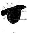
- FIG 7
- shows an embodiment of the invention where a rechargeable battery is used.
- The battery lid shown in fig. 1A and 1B has a
first side 1, which is facing the exterior and asecond side 2 which faces the interior of the casing (not shown). Thesecond side 2 is usually shaped to snugly fit the curvature of the battery. This can be seen in fig. 1C, where thebattery 6 is shown. In the embodiment of fig. 1A and 1B arecess 3 is shaped between the twosurfaces interior surface 2 and according to the embodiment of fig. 1B the recess is sideways open and in both cases a microphone is insertable in therecess 3. From the bottom of the recess 3 acanal 4 is formed, which allows sound from the outside to enter the microphone port. - In fig. 1C the
battery 6 and battery lid is shown in perspective view along with a faceplate part 5. In the figure the lid is shown in the open position, and the material between thefirst surface 1 facing the surroundings and thesecond surface 2 facing theinterior 2 when the lid is in the closed position is used for the recess to accommodate the microphone (not shown in this figure). Ahinge pin 14 is shown in fig. 1C and ahinge pin hole 15 is shown in fig. 1A and 1B. The battery lids shown in figs. 2-5 may have similar holes for mounting in the faceplate, or they may be mounted in some other way. - In figures 2A and 2B a further embodiment is shown. Here the battery lid accommodates two
microphones microphones flex print strip 7. During production the microphones and flex print assembly is placed in an injection mold, and the material of the battery lid is filled into the mould cavity around theflex print strip 7 and battery assembly. Thecanals 4 leading from thefirst side 1 of the battery lid to the active surface of a microphone are also shaped in the injection molding procedure. In order to protect the microphones from the hot melt during the injection molding the microphones may be surrounded be a shielding material like µ-metal. Such a shielding may also protect the microphones against electro-magnetic interference. Also a material with a low melting point or a hardening material may be used in order not to harm the microphone. - The two microphones may be used to generate a directional signal or they may simply be used so as to improve the overall signal to noise ratio.
- In the embodiment of fig. 3A and 3B a different solution is shown. Here the microphone and flexprint assembly is placed in a
recess 3 in thesecond side 2 of the battery lid. A holding member 9 is inserted from theback side 2 and fixates the flexprint and microphone assembly. This has the advantage that the microphones are exchangeable, and can be replaced in the event of malfunction. A packing material (not shown) is advantageously used to ensure sound tight joints towards theback side 2 of the battery lid. - In fig. 4A and 4B a further possible solution is shown. Here the holding member is replaced by the use of glue or similar joining technique between the flexprint and microphone assembly and the battery lid.
- In fig. 5A and 5B it is shown how the
amplifier 10 is placed. Here the flexprint extends outside the material of the battery lid in acurve 11 following the curvature of the battery. In the shown embodiment the battery lid has aback part 16, supporting the battery inside the casing and the flexprint follows the outside curve of thisback part 16 to meet with the amplifier inside the casing. As seen theamplifier 10 may be mounted directly on theback part 16 of the battery lid. Also in this figure a shiftingmember 13 is shown between the two microphones. The shifting member could be a button for changing program or it could be a volume control button. The shiftingmember 13 is advantageous placed on the same flexprint as themicrophones - In the embodiments according to figs. 2 - 4 two microphones are shown, and they are placed at each their end of the battery lid. As seen from the figures the
first surface 1 of the battery lid is rather flat, where as thesecond surface 2 follows the curvature of the battery, and therefore the battery lid has a little more material at each end thereof. This makes the placement of the two microphones in these areas advantageous. Other wayes of placing the microphones within the battery lid materiel is possible. - In fig. 6 a BTE
style hearing aid 14 is shown wherein the invention is realized. The battery lid has afirst side 1 facing the environment and asecond side 2 facing the inside of the casing. In thefirst side 1 two microphonesound entrance canals 4 are arranged, and behind thecanals 4 recesses are provided for microphones (not shown). The two microphones are placed at each their side of the battery in an area where space is naturally provided by the curvature of the battery. The solutions shown in figs 2- 5 for accommodating the microphones may also be used in connection with the BTE stile hearing aid shown in fig. 6. - The hearing aid part in fig. 7 has a
rechargeable battery 6, which is encased in the shell material of the hearing aid. A rechargeable battery does not need to be exchanged at regular intervals, and a battery lid as such is not required. Possibly the whole unit displayed in fig. 7 can be a disposable part of the hearing aid, which is discarded once the battery lifetime is up. Alternatively the battery is extractable, through a service opening, but this is not shown.Canals 4 are provided for the sound waves to reach themicrophones microphones element 13 is placed between themicrophone sound canals 4.
Claims (12)
- Method of producing a hearing aid comprising a casing and at least one transducer (11,12) and a signal path from the transducer (11,12) to a receiver which provides a sound signal at the ear of the user, wherein signal processing is provided in the signal path to ensure a signal amplification/attenuation according to the needs of the user, wherein the at least one transducer (11,12) is being embedded within the material of a casing part during the production thereof so that a sound transmission path is provided between an exterior surface (1) of the casing part and the at least one transducer (11,12).
- Method as claimed in claim 1, wherein the transducer is a MEMS microphone.
- Method as claimed in claim 1, wherein the casing is produced by injection moulding.
- Method as claimed in claim 1, wherein the at least one microphone is mounted to a print and where the print and microphone assembly is embedded in the casing material during the production of the casing, such that at least an edge part of the print is connectable from the inside of the casing.
- Hearing aid comprising a casing accommodating one or more sound to electric signal converting transducers (11,12) and a signal path from the transducer (11,12) to a receiver which in use provides a sound signal at the ear of the user, wherein signal processing is provided in the signal path to ensure a signal amplification/attenuation according to the needs of the user, wherein a battery (6) is accommodated in the casing and where a battery lid is arranged with a first side (1) facing the surrounding and a second side (2) facing the interior of the casing wherein the battery lid is operable for replacement of the battery, wherein the battery lid has means (3) for receiving at least one sound to electric signal converting transducer (11,12) and wherein a sound transmission path is provided between the first side (1) of the battery lid and the at least one transducer (11,12).
- Hearing aid as claimed in claim 5, wherein the at least one transducer (11,12) is a MEMS microphone.
- Hearing aid as claimed in claim 5, wherein the transducer or the transducers (11,12) are arranged on a first side of a flexprint (7) having electric leads which provides a signal path from the transducers (11,12) to a signal processing device (10).
- Hearing aid as claimed in claim 7, wherein the flexprint (7) along with the transducers (11,12) thereon are embedded in the material of the battery lid, and where the flexprint (7) extends outside the material of the battery lid.
- Hearing aid as claimed in claim 7, wherein the battery lid has a recess (3) in the second side thereof facing the interior of the casing, and where the flexprint (7) and the at least one transducer (11,12) is retained in the recess (3) by the use of a retaining element (9).
- Hearing aid as claimed in claim 7 wherein the flexprint (7) and the at least one transducer (11,12) is retained against the second side of the battery lid by the use of glue or similar fastening technique.
- Hearing aid as claimed in one or more of claims 5-7, wherein the flexprint (7) with the at least one transducer (11,12) extends in an arch following the curvature of the battery exterior, and is electrically connected to the signal processing device (10) inside the casing.
- Hearing aid as claimed in any one of claims 7-11, wherein a switching element (13) is placed in the battery lid and extends away from the first side (1) of the battery lid.
Applications Claiming Priority (3)
| Application Number | Priority Date | Filing Date | Title |
|---|---|---|---|
| DK200101823 | 2001-12-07 | ||
| DKPA200101823 | 2001-12-07 | ||
| PCT/DK2002/000810 WO2003049495A1 (en) | 2001-12-07 | 2002-12-02 | Method for producing a hearing aid |
Publications (2)
| Publication Number | Publication Date |
|---|---|
| EP1459595A1 EP1459595A1 (en) | 2004-09-22 |
| EP1459595B1 true EP1459595B1 (en) | 2005-05-18 |
Family
ID=8160882
Family Applications (1)
| Application Number | Title | Priority Date | Filing Date |
|---|---|---|---|
| EP02804163A Expired - Lifetime EP1459595B1 (en) | 2001-12-07 | 2002-12-02 | Method for producing a hearing aid |
Country Status (7)
| Country | Link |
|---|---|
| US (1) | US7254247B2 (en) |
| EP (1) | EP1459595B1 (en) |
| AT (1) | ATE296023T1 (en) |
| AU (1) | AU2002365816A1 (en) |
| DE (1) | DE60204241T2 (en) |
| DK (1) | DK1459595T3 (en) |
| WO (1) | WO2003049495A1 (en) |
Families Citing this family (23)
| Publication number | Priority date | Publication date | Assignee | Title |
|---|---|---|---|---|
| WO2002051203A1 (en) * | 2000-12-19 | 2002-06-27 | Oticon A/S | Communication system |
| AU2003232177A1 (en) * | 2002-07-10 | 2004-02-02 | Oticon A/S | Hearing aid or similar audio device and method for producing a hearing aid |
| US7142682B2 (en) | 2002-12-20 | 2006-11-28 | Sonion Mems A/S | Silicon-based transducer for use in hearing instruments and listening devices |
| DE10260303B3 (en) * | 2002-12-20 | 2004-06-17 | Siemens Audiologische Technik Gmbh | Microphone module for hearing aid, has several microphones attached to common carrier and electrically connected via 3-dimensional conductor paths |
| DE10343292B3 (en) | 2003-09-18 | 2004-12-02 | Siemens Audiologische Technik Gmbh | Hearing aid e.g. for hearing impaired people, without separate microphone housing, has hearing aid housing and a microphone housing which are formed from a one-piece with housing having cover for acoustic isolation |
| SE525631C2 (en) * | 2003-09-19 | 2005-03-22 | P & B Res Ab | Method and apparatus for attenuating resonant frequency |
| US7443992B2 (en) * | 2004-04-15 | 2008-10-28 | Starkey Laboratories, Inc. | Method and apparatus for modular hearing aid |
| JP4289376B2 (en) * | 2006-08-18 | 2009-07-01 | ソニー株式会社 | headset |
| US8180084B2 (en) * | 2007-03-21 | 2012-05-15 | Starkey Laboratories, Inc. | Integrated battery door and switch |
| CA2696859A1 (en) * | 2007-09-05 | 2007-11-29 | Phonak Ag | Battery lock |
| DE102007055384A1 (en) * | 2007-11-20 | 2009-05-28 | Siemens Medical Instruments Pte. Ltd. | Hearing aid, in particular IO hearing aid |
| EP2107823B1 (en) * | 2008-04-02 | 2013-06-19 | Starkey Laboratories, Inc. | Method and apparatus for microphones sharing a common acoustic volume |
| DK2254353T3 (en) * | 2009-05-19 | 2017-10-23 | Sivantos Pte Ltd | Hearing aid with a sound converter and method for making a sound converter |
| JP4554718B1 (en) * | 2009-06-12 | 2010-09-29 | パナソニック株式会社 | hearing aid |
| US20110068502A1 (en) * | 2009-09-21 | 2011-03-24 | Basseas Stavros P | Custom Injection Mold and Molding Process Using Rapid Prototyping Processes |
| DE102009056916B4 (en) * | 2009-12-03 | 2011-07-21 | Siemens Medical Instruments Pte. Ltd. | Hearing aid with a space-saving arrangement of microphones and sound openings |
| DE102012203768A1 (en) * | 2012-03-09 | 2013-09-12 | Siemens Medical Instruments Pte. Ltd. | Battery holder for a hearing aid |
| US8976957B2 (en) | 2013-05-15 | 2015-03-10 | Google Technology Holdings LLC | Headset microphone boom assembly |
| DK3422741T3 (en) * | 2014-04-07 | 2020-08-03 | Oticon As | HEARING AID DEVICE THAT HAS A BATTERY DRAWER |
| EP3157269A1 (en) * | 2015-10-13 | 2017-04-19 | Sonion A/S | Compact housing assembly or faceplate layout |
| DE102017201465B4 (en) * | 2017-01-30 | 2021-10-21 | Sivantos Pte. Ltd. | Microphone unit with a housing |
| EP3823305A1 (en) * | 2019-11-15 | 2021-05-19 | GN Hearing A/S | Compact, watertight and acoustically-tight button structure |
| US11729560B1 (en) | 2022-03-31 | 2023-08-15 | Sonova Ag | Battery compartment of a hearing device configured to inhibit the ingress of debris into the battery compartment |
Family Cites Families (10)
| Publication number | Priority date | Publication date | Assignee | Title |
|---|---|---|---|---|
| DE9415594U1 (en) * | 1994-09-29 | 1996-02-08 | Toepholm & Westermann | Hearing aid |
| US2787670A (en) * | 1953-02-27 | 1957-04-02 | Douglas H Rowland | Hearing aid |
| US2789160A (en) * | 1953-10-29 | 1957-04-16 | Sonotone Corp | Wearable hearing aid with a common casing for amplifier and batteries |
| US4712245A (en) * | 1985-01-24 | 1987-12-08 | Oticon Electronics A/S | In-the-ear hearing aid with the outer wall formed by rupturing a two-component chamber |
| DE3603704C2 (en) | 1986-02-06 | 1995-04-20 | Ascom Audiosys Ag | Hearing aid to be worn in the ear |
| JP2000508860A (en) * | 1996-04-18 | 2000-07-11 | カリフォルニア インスティチュート オブ テクノロジー | Thin film electret microphone |
| DE19706306C1 (en) * | 1997-02-18 | 1998-10-08 | Siemens Audiologische Technik | In-ear hearing aid |
| DK42197A (en) * | 1997-04-15 | 1998-10-16 | Toepholm & Westermann | Compact modulated in-ear hearing aid |
| AUPP052097A0 (en) | 1997-11-24 | 1997-12-18 | Nhas National Hearing Aids Systems | Hearing aid |
| US6516074B1 (en) * | 2000-10-19 | 2003-02-04 | Sonic Innovations, Inc. | Hearing device with integrated battery compartment and switch |
-
2002
- 2002-12-02 DE DE60204241T patent/DE60204241T2/en not_active Expired - Lifetime
- 2002-12-02 US US10/497,855 patent/US7254247B2/en not_active Expired - Fee Related
- 2002-12-02 WO PCT/DK2002/000810 patent/WO2003049495A1/en not_active Application Discontinuation
- 2002-12-02 AT AT02804163T patent/ATE296023T1/en not_active IP Right Cessation
- 2002-12-02 EP EP02804163A patent/EP1459595B1/en not_active Expired - Lifetime
- 2002-12-02 DK DK02804163T patent/DK1459595T3/en active
- 2002-12-02 AU AU2002365816A patent/AU2002365816A1/en not_active Abandoned
Also Published As
| Publication number | Publication date |
|---|---|
| US20050123157A1 (en) | 2005-06-09 |
| DE60204241D1 (en) | 2005-06-23 |
| DE60204241T2 (en) | 2006-01-26 |
| ATE296023T1 (en) | 2005-06-15 |
| EP1459595A1 (en) | 2004-09-22 |
| US7254247B2 (en) | 2007-08-07 |
| DK1459595T3 (en) | 2005-08-22 |
| WO2003049495A1 (en) | 2003-06-12 |
| WO2003049495A8 (en) | 2003-08-28 |
| AU2002365816A1 (en) | 2003-06-17 |
Similar Documents
| Publication | Publication Date | Title |
|---|---|---|
| EP1459595B1 (en) | Method for producing a hearing aid | |
| US6731770B1 (en) | Behind-the-ear hearing aid and surface-mounted module for this type of hearing aid | |
| US7099484B2 (en) | Behind-the-ear hearing aid | |
| US6735319B1 (en) | Behind-the-ear hearing aid | |
| US10034107B2 (en) | Hearing aid | |
| CN102396244B (en) | Receiver assemblies | |
| US7155023B2 (en) | Switch for a body-worn electronic device | |
| US20080095392A1 (en) | Hearing aid with sound tube serving for retention in concha | |
| EP1120010B1 (en) | A hearing aid | |
| EP1120009A2 (en) | A hearing aid | |
| EP2750413B1 (en) | Hearing aid device | |
| EP1483938B1 (en) | Microphone and battery configuration for hearing instruments | |
| JP4546738B2 (en) | Apparatus having an interface frame and manufacturing process thereof | |
| EP1692918B1 (en) | Communication device with microphone | |
| WO2004036953A1 (en) | Hearing prosthesis | |
| US20110211718A1 (en) | Hearing aid | |
| US20030089548A1 (en) | In the ear hearing aid | |
| CN106165450B (en) | The method of ITE hearing aid and manufacture ITE hearing aid | |
| EP1692914B1 (en) | Communication device with receiver enclosure | |
| US20120128188A1 (en) | Hearing aid | |
| US20230336929A1 (en) | Removable battery designs for custom hearing instruments | |
| EP3958590A1 (en) | A socket connector for a hearing device | |
| US8611573B2 (en) | Hearing aid with audio shoe |
Legal Events
| Date | Code | Title | Description |
|---|---|---|---|
| PUAI | Public reference made under article 153(3) epc to a published international application that has entered the european phase |
Free format text: ORIGINAL CODE: 0009012 |
|
| 17P | Request for examination filed |
Effective date: 20040707 |
|
| AK | Designated contracting states |
Kind code of ref document: A1 Designated state(s): AT BE BG CH CY CZ DE DK EE ES FI FR GB GR IE IT LI LU MC NL PT SE SI SK TR |
|
| GRAP | Despatch of communication of intention to grant a patent |
Free format text: ORIGINAL CODE: EPIDOSNIGR1 |
|
| GRAS | Grant fee paid |
Free format text: ORIGINAL CODE: EPIDOSNIGR3 |
|
| GRAA | (expected) grant |
Free format text: ORIGINAL CODE: 0009210 |
|
| AK | Designated contracting states |
Kind code of ref document: B1 Designated state(s): AT BE BG CH CY CZ DE DK EE ES FI FR GB GR IE IT LI LU MC NL PT SE SI SK TR |
|
| PG25 | Lapsed in a contracting state [announced via postgrant information from national office to epo] |
Ref country code: IT Free format text: LAPSE BECAUSE OF FAILURE TO SUBMIT A TRANSLATION OF THE DESCRIPTION OR TO PAY THE FEE WITHIN THE PRESCRIBED TIME-LIMIT;WARNING: LAPSES OF ITALIAN PATENTS WITH EFFECTIVE DATE BEFORE 2007 MAY HAVE OCCURRED AT ANY TIME BEFORE 2007. THE CORRECT EFFECTIVE DATE MAY BE DIFFERENT FROM THE ONE RECORDED. Effective date: 20050518 Ref country code: CZ Free format text: LAPSE BECAUSE OF FAILURE TO SUBMIT A TRANSLATION OF THE DESCRIPTION OR TO PAY THE FEE WITHIN THE PRESCRIBED TIME-LIMIT Effective date: 20050518 Ref country code: NL Free format text: LAPSE BECAUSE OF FAILURE TO SUBMIT A TRANSLATION OF THE DESCRIPTION OR TO PAY THE FEE WITHIN THE PRESCRIBED TIME-LIMIT Effective date: 20050518 Ref country code: EE Free format text: LAPSE BECAUSE OF FAILURE TO SUBMIT A TRANSLATION OF THE DESCRIPTION OR TO PAY THE FEE WITHIN THE PRESCRIBED TIME-LIMIT Effective date: 20050518 Ref country code: AT Free format text: LAPSE BECAUSE OF FAILURE TO SUBMIT A TRANSLATION OF THE DESCRIPTION OR TO PAY THE FEE WITHIN THE PRESCRIBED TIME-LIMIT Effective date: 20050518 Ref country code: SK Free format text: LAPSE BECAUSE OF FAILURE TO SUBMIT A TRANSLATION OF THE DESCRIPTION OR TO PAY THE FEE WITHIN THE PRESCRIBED TIME-LIMIT Effective date: 20050518 Ref country code: FI Free format text: LAPSE BECAUSE OF FAILURE TO SUBMIT A TRANSLATION OF THE DESCRIPTION OR TO PAY THE FEE WITHIN THE PRESCRIBED TIME-LIMIT Effective date: 20050518 Ref country code: TR Free format text: LAPSE BECAUSE OF FAILURE TO SUBMIT A TRANSLATION OF THE DESCRIPTION OR TO PAY THE FEE WITHIN THE PRESCRIBED TIME-LIMIT Effective date: 20050518 Ref country code: SI Free format text: LAPSE BECAUSE OF FAILURE TO SUBMIT A TRANSLATION OF THE DESCRIPTION OR TO PAY THE FEE WITHIN THE PRESCRIBED TIME-LIMIT Effective date: 20050518 Ref country code: BE Free format text: LAPSE BECAUSE OF FAILURE TO SUBMIT A TRANSLATION OF THE DESCRIPTION OR TO PAY THE FEE WITHIN THE PRESCRIBED TIME-LIMIT Effective date: 20050518 |
|
| REG | Reference to a national code |
Ref country code: GB Ref legal event code: FG4D |
|
| REG | Reference to a national code |
Ref country code: CH Ref legal event code: EP |
|
| REG | Reference to a national code |
Ref country code: IE Ref legal event code: FG4D |
|
| REF | Corresponds to: |
Ref document number: 60204241 Country of ref document: DE Date of ref document: 20050623 Kind code of ref document: P |
|
| REG | Reference to a national code |
Ref country code: CH Ref legal event code: NV Representative=s name: SCHNEIDER FELDMANN AG PATENT- UND MARKENANWAELTE |
|
| PG25 | Lapsed in a contracting state [announced via postgrant information from national office to epo] |
Ref country code: BG Free format text: LAPSE BECAUSE OF FAILURE TO SUBMIT A TRANSLATION OF THE DESCRIPTION OR TO PAY THE FEE WITHIN THE PRESCRIBED TIME-LIMIT Effective date: 20050818 Ref country code: SE Free format text: LAPSE BECAUSE OF FAILURE TO SUBMIT A TRANSLATION OF THE DESCRIPTION OR TO PAY THE FEE WITHIN THE PRESCRIBED TIME-LIMIT Effective date: 20050818 Ref country code: GR Free format text: LAPSE BECAUSE OF FAILURE TO SUBMIT A TRANSLATION OF THE DESCRIPTION OR TO PAY THE FEE WITHIN THE PRESCRIBED TIME-LIMIT Effective date: 20050818 |
|
| REG | Reference to a national code |
Ref country code: DK Ref legal event code: T3 |
|
| PG25 | Lapsed in a contracting state [announced via postgrant information from national office to epo] |
Ref country code: ES Free format text: LAPSE BECAUSE OF FAILURE TO SUBMIT A TRANSLATION OF THE DESCRIPTION OR TO PAY THE FEE WITHIN THE PRESCRIBED TIME-LIMIT Effective date: 20050829 |
|
| PG25 | Lapsed in a contracting state [announced via postgrant information from national office to epo] |
Ref country code: PT Free format text: LAPSE BECAUSE OF FAILURE TO SUBMIT A TRANSLATION OF THE DESCRIPTION OR TO PAY THE FEE WITHIN THE PRESCRIBED TIME-LIMIT Effective date: 20051024 |
|
| NLV1 | Nl: lapsed or annulled due to failure to fulfill the requirements of art. 29p and 29m of the patents act | ||
| PG25 | Lapsed in a contracting state [announced via postgrant information from national office to epo] |
Ref country code: CY Free format text: LAPSE BECAUSE OF FAILURE TO SUBMIT A TRANSLATION OF THE DESCRIPTION OR TO PAY THE FEE WITHIN THE PRESCRIBED TIME-LIMIT Effective date: 20051202 Ref country code: IE Free format text: LAPSE BECAUSE OF NON-PAYMENT OF DUE FEES Effective date: 20051202 |
|
| PG25 | Lapsed in a contracting state [announced via postgrant information from national office to epo] |
Ref country code: LU Free format text: LAPSE BECAUSE OF NON-PAYMENT OF DUE FEES Effective date: 20051231 Ref country code: MC Free format text: LAPSE BECAUSE OF NON-PAYMENT OF DUE FEES Effective date: 20051231 |
|
| RAP2 | Party data changed (patent owner data changed or rights of a patent transferred) |
Owner name: OTICON A/S |
|
| PLBE | No opposition filed within time limit |
Free format text: ORIGINAL CODE: 0009261 |
|
| STAA | Information on the status of an ep patent application or granted ep patent |
Free format text: STATUS: NO OPPOSITION FILED WITHIN TIME LIMIT |
|
| ET | Fr: translation filed | ||
| 26N | No opposition filed |
Effective date: 20060221 |
|
| REG | Reference to a national code |
Ref country code: IE Ref legal event code: MM4A |
|
| PGFP | Annual fee paid to national office [announced via postgrant information from national office to epo] |
Ref country code: CH Payment date: 20121217 Year of fee payment: 11 Ref country code: DK Payment date: 20121227 Year of fee payment: 11 |
|
| PGFP | Annual fee paid to national office [announced via postgrant information from national office to epo] |
Ref country code: GB Payment date: 20121220 Year of fee payment: 11 |
|
| PGFP | Annual fee paid to national office [announced via postgrant information from national office to epo] |
Ref country code: FR Payment date: 20130123 Year of fee payment: 11 Ref country code: DE Payment date: 20121219 Year of fee payment: 11 |
|
| REG | Reference to a national code |
Ref country code: DE Ref legal event code: R119 Ref document number: 60204241 Country of ref document: DE |
|
| REG | Reference to a national code |
Ref country code: DK Ref legal event code: EBP Effective date: 20131231 |
|
| REG | Reference to a national code |
Ref country code: CH Ref legal event code: PL |
|
| GBPC | Gb: european patent ceased through non-payment of renewal fee |
Effective date: 20131202 |
|
| REG | Reference to a national code |
Ref country code: FR Ref legal event code: ST Effective date: 20140829 |
|
| REG | Reference to a national code |
Ref country code: DE Ref legal event code: R119 Ref document number: 60204241 Country of ref document: DE Effective date: 20140701 |
|
| PG25 | Lapsed in a contracting state [announced via postgrant information from national office to epo] |
Ref country code: LI Free format text: LAPSE BECAUSE OF NON-PAYMENT OF DUE FEES Effective date: 20131231 Ref country code: CH Free format text: LAPSE BECAUSE OF NON-PAYMENT OF DUE FEES Effective date: 20131231 Ref country code: DE Free format text: LAPSE BECAUSE OF NON-PAYMENT OF DUE FEES Effective date: 20140701 |
|
| PG25 | Lapsed in a contracting state [announced via postgrant information from national office to epo] |
Ref country code: GB Free format text: LAPSE BECAUSE OF NON-PAYMENT OF DUE FEES Effective date: 20131202 Ref country code: FR Free format text: LAPSE BECAUSE OF NON-PAYMENT OF DUE FEES Effective date: 20131231 |
|
| PG25 | Lapsed in a contracting state [announced via postgrant information from national office to epo] |
Ref country code: DK Free format text: LAPSE BECAUSE OF NON-PAYMENT OF DUE FEES Effective date: 20131231 |