EP1456992B1 - Transmission configuration for continuous-time data transmission - Google Patents
Transmission configuration for continuous-time data transmission Download PDFInfo
- Publication number
- EP1456992B1 EP1456992B1 EP02792669A EP02792669A EP1456992B1 EP 1456992 B1 EP1456992 B1 EP 1456992B1 EP 02792669 A EP02792669 A EP 02792669A EP 02792669 A EP02792669 A EP 02792669A EP 1456992 B1 EP1456992 B1 EP 1456992B1
- Authority
- EP
- European Patent Office
- Prior art keywords
- signal
- amplifier
- coupled
- transmission arrangement
- control
- Prior art date
- Legal status (The legal status is an assumption and is not a legal conclusion. Google has not performed a legal analysis and makes no representation as to the accuracy of the status listed.)
- Expired - Lifetime
Links
- 230000005540 biological transmission Effects 0.000 title claims description 64
- 238000012545 processing Methods 0.000 claims description 19
- 238000000034 method Methods 0.000 claims description 5
- 230000001629 suppression Effects 0.000 claims description 5
- 230000009467 reduction Effects 0.000 description 8
- 230000003321 amplification Effects 0.000 description 7
- 238000003199 nucleic acid amplification method Methods 0.000 description 7
- 239000013598 vector Substances 0.000 description 5
- 230000008901 benefit Effects 0.000 description 4
- 238000013461 design Methods 0.000 description 3
- 238000011161 development Methods 0.000 description 3
- 238000004519 manufacturing process Methods 0.000 description 3
- 238000010586 diagram Methods 0.000 description 2
- 230000005611 electricity Effects 0.000 description 2
- 238000010295 mobile communication Methods 0.000 description 2
- 230000001105 regulatory effect Effects 0.000 description 2
- 238000001228 spectrum Methods 0.000 description 2
- 239000000758 substrate Substances 0.000 description 2
- 238000012546 transfer Methods 0.000 description 2
- 230000006978 adaptation Effects 0.000 description 1
- 230000009286 beneficial effect Effects 0.000 description 1
- 230000033228 biological regulation Effects 0.000 description 1
- 230000000295 complement effect Effects 0.000 description 1
- 230000008878 coupling Effects 0.000 description 1
- 238000010168 coupling process Methods 0.000 description 1
- 238000005859 coupling reaction Methods 0.000 description 1
- 238000013016 damping Methods 0.000 description 1
- 230000001419 dependent effect Effects 0.000 description 1
- 230000008030 elimination Effects 0.000 description 1
- 238000003379 elimination reaction Methods 0.000 description 1
- 238000005516 engineering process Methods 0.000 description 1
- 230000007613 environmental effect Effects 0.000 description 1
- 230000005669 field effect Effects 0.000 description 1
- 230000006872 improvement Effects 0.000 description 1
- 230000003993 interaction Effects 0.000 description 1
- 230000013011 mating Effects 0.000 description 1
- 230000004044 response Effects 0.000 description 1
- 230000003595 spectral effect Effects 0.000 description 1
- 230000007704 transition Effects 0.000 description 1
- 238000011144 upstream manufacturing Methods 0.000 description 1
Images

Classifications
-
- H—ELECTRICITY
- H03—ELECTRONIC CIRCUITRY
- H03G—CONTROL OF AMPLIFICATION
- H03G3/00—Gain control in amplifiers or frequency changers
- H03G3/20—Automatic control
- H03G3/30—Automatic control in amplifiers having semiconductor devices
- H03G3/3036—Automatic control in amplifiers having semiconductor devices in high-frequency amplifiers or in frequency-changers
- H03G3/3042—Automatic control in amplifiers having semiconductor devices in high-frequency amplifiers or in frequency-changers in modulators, frequency-changers, transmitters or power amplifiers
-
- H—ELECTRICITY
- H03—ELECTRONIC CIRCUITRY
- H03G—CONTROL OF AMPLIFICATION
- H03G3/00—Gain control in amplifiers or frequency changers
- H03G3/20—Automatic control
- H03G3/30—Automatic control in amplifiers having semiconductor devices
- H03G3/3089—Control of digital or coded signals
Definitions
- the present invention relates to a transmission arrangement for a continuous-time data transmission.
- Bursts While not with second-generation mobile phones time-continuous, but in time windows, so-called Bursts being sent use modern transmission methods, for example, according to Universal Mobile Telecommunications System (UMTS) standard, continuous-time transmission method.
- UMTS Universal Mobile Telecommunications System
- UMTS mobile devices must be capable of transmitting power during a data transmission continuously to the changing Adapt conditions.
- the transmission power can depend on the current receive field strength of the handset or be specified by a base station.
- the object of the present invention is a transmission arrangement for a time-continuous data transmission, which is suitable for UMTS and improved in terms of power consumption is.
- claim 1 thereby distinguishes from US-A-5,708,681 in that an active amplification is performed in front of the quadrature modulator, and in a feedback path means for carrier frequency rejection is provided with an input connected to the output of the quadrature modulator is coupled, and with an output that with the inphase and with the Quadrature signal path is coupled.
- the present principle is to influence the transmission power the transmission arrangement at least one programmable Amplifier used with a discrete-value control signal is controlled.
- AGC automatic gain control
- the invention is further a feedback loop for carrier frequency rejection provided with a feedback path, the output of the quadrature modulator with its inphase and its quadrature signal input.
- Such Feedback loop can, for example, frequency components at the carrier frequency, which as noise at the output of the modulator occur in their amplitude detect and to the feedable at the input of the quadrature modulator Signal components with respect to DC offset between the symmetric components in in-phase branch and / or Quadrature branch act so that the carrier frequency disappears or is as small as possible.
- the present principle for establishing a transmission arrangement for continuous-time data transmission is based on the knowledge that at the time-continuous data transmission at simultaneous fulfillment of specification limits, in particular in terms of high-frequency spectrum and the Size of error vectors, yet on a continuous value controlled, automatic gain control omitted can be.
- the control voltage instead for the gain control digital, that is time and discrete value present, can advantageously with the present principle to dispense with digital / analog converter.
- a voltage signal is in the baseband signal processing unit usually depending on the current reception field strength, the so-called received signal Strength Indicator, RSSI derived.
- RSSI received signal Strength Indicator
- With the D / A converter can also use downstream filters to reconstruct the omitted analog control signal.
- the digital data format of the control signal has the additional Advantage that an improvement in the susceptibility to an analog signal is achieved.
- the accuracy of the transmission power control For example, in a handset in which the transmission arrangement is provided, be increased significantly.
- this control signal is insensitive to Temperature influences, substrate noise, which the D / A converter would affect fluctuations in the operating voltage as well as manufacturing fluctuations.
- One for complex valued Signal processing designed transmitter in which the requirements for mating tolerances in the complementary Signal branches used components very high is an added benefit by inserting a Discrete-value control of the programmable amplifier achieved.
- the first programmable Amplifier implemented programmable amplifier an additional second programmable amplifier provided, one each in the baseband signal processing unit and one arranged in the high-frequency branch is.
- the base band, the first programmable amplifier is of course both in-phase as also provided in the quadrature signal branch.
- the described, programmable amplifiers are each controlled with a discrete-value control signal.
- the distribution of signal amplification on baseband and high frequency branch allows a particularly high flexibility in the design of the amplification stages and in the adaptation of the timing.
- there is the advantage of being able to Baseband ICs and high-frequency ICs of various types To be able to combine types or manufacturers.
- programmable amplifier which is arranged in the baseband, a gain of one Dynamic range of 20 to 30 dB, while the gain in the high-frequency branch preferably a dynamic range from 50 to 60 dB.
- the transmission arrangement may preferably be in the baseband signal processing unit or in the high-frequency branch one passive, programmable amplifier, with a Control input to the control unit to provide a discrete-value signal attenuation is coupled.
- the passive, programmable amplifier can be used as a resistor network be executed.
- the passive, programmable amplifier attenuates the signal to be sent Signal.
- the damping is in discrete-value steps adjustable. With such a passive control is a Reduction of power consumption and a low Substrate noise without reducing the dynamic range of the Transmitter achievable.
- the passive, programmable amplifier is preferably at the output connected to the quadrature modulator.
- the passive, programmable amplifier at the output of the quadrature modulator is preferably an active, programmable Amplifier upstream.
- the passive, programmable amplifier is in Adjustable steps of 6 dB.
- the first, active, programmable Amplifier in the baseband signal processing unit is preferably adjustable in increments of 1 dB.
- the second, active, programmable amplifiers in the high-frequency branch is preferably adjustable in steps of 6 dB.
- the programmable amplifier comprises several, in parallel and independently switched on and off Amplifier branches, wherein the switching on and off of the amplifier branches depending on the value discrete control signal he follows.
- the respectively not required amplifier branches can be switched off, that is, their power sources are disabled, so that the power requirement of the programmable, active amplifier or the programmable amplifier drops.
- a transmission arrangement for example in mobile communications, the majority the operating time does not work with maximum transmission power, is with the described division of the programmable Amplifier on several, independently from each other and switchable branches, a significant reduction in power consumption possible.
- Invention includes the programmable gain Means for adjusting the rise time of the gain on.
- the means for adjusting the rise time allows when switching the programmable amplifier from one Amplifier stage on another amplifier stage no jumpy Changing the gain takes place, but a soft transition is possible. This will cause unwanted, High frequency signal components when switching significantly reduced and also the amplitude of the error vector when switching reduced.
- the control signal for driving such a further developed, Programmable amplifier is still a value discrete Control signal.
- the transmission arrangement is preferred in a mobile radio transmitter intended.
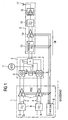
- FIG. 1 shows a transmission arrangement designed for continuous-time transmission Data transfer.
- This comprises a baseband signal processing unit 1, a quadrature modulator 2 and a radio frequency branch 3.
- the baseband signal processing unit 1 is designed for complex-valued signal processing and for this purpose comprises an in-phase branch 4 and a quadrature signal path 5.
- In-phase and quadrature signal paths 4, 5 are respectively designed to transmit symmetrical signals.
- inphase and quadrature signal paths 4, 5 each have a low-pass filter 6, each with a first programmable amplifier 7 is connected downstream.
- the first programmable amplifier 7 each have a control input for supplying a discrete-value control signal to the output of a Control unit 8 via a digital Dreileiterbus according to the 3Wire bus specification is connected.
- the quadrature modulator 2 comprises two Gilbert multipliers 9, with their first input pair with one output each of a first programmable Amplifier 7 are connected and their second input pair via a 0 degree / 90 degree frequency divider 10 to a voltage controlled Oscillator 11 for providing a complex-valued Signal connected to a carrier frequency is.
- the outputs of the two Gilbert multipliers 9 are on depending on an input pair of a summing node 12 connected, whose output forms the output of the quadrature modulator 2.
- the high frequency branch 3 connected, which is a passive, programmable Amplifier 13, a second programmable amplifier 14, a bandpass filter 15 and a power amplifier 16 includes.
- the power amplifier 16 has an output, the same time forms the output of the high-frequency branch 3 and which is coupled to an antenna 17.
- the passive, programmable Amplifier 13 is symmetrical with its input to the trained output of the summing node 12 connected.
- the output of the passive, programmable amplifier 13 is connected to the input of the second programmable Amplifier 14, which is an active amplifier connected.
- a bandpass filter 15 is connected.
- the output of the bandpass filter 15 is connected to an input of the power amplifier 16 coupled.
- Both the passive, programmable amplifier 13, as well as the second programmable amplifier 14 are to their Control with the control unit 8 via the three-wire bus connected.
- the described transmission arrangement for continuous-time data transmission is therefore as a homodyne transmitter or direct converter educated.
- the control of the programmable amplifier 7, 13, 14th by the control unit 8 by means of discrete-value signals.
- the transmission arrangement is for a continuous time Data transmission according to CDMA designed and as a UMTS transmitter educated. In such mobile devices according to UMTS standard is usually in addition to the shown transmission branch in addition a reception branch not shown in FIG Forming a transceiver provided.
- the total, controllable amplification of the transmission arrangement is for Achieve a large dynamic range on two active, programmable Amplifier stages 7, 14 and a passive, programmable Amplifier stage 13 distributed. It is in the Baseband signal processing unit 1 a gain control in the range of about 20 to 30 dB, while in the high-frequency branch 3 a dynamic range of about 50 to 60 dB as Control range is provided. Because at the output of the quadrature modulator advantageously a power level of about -10 dBm must be at the output of the quadrature modulator 2, a gain control range of about +15 to -45 be provided dB.
- a passive, programmable gain stage 13 which in the present embodiment as a controllable resistor network is executed.
- the passive programmable amplifier 13 and the second programmable amplifier 14 in steps adjustable by 6 dB.
- the first programmable amplifier 7 in baseband is adjustable in discrete steps of 1 dB.
- the amplification factors of the amplifiers 7, 13, 14 are thus not, as is usual with continuous data transmission systems provided, value-continuous, but value-discreet adjustable.
- Baseband and high frequency gain control can be total a resolution of the gain control of 1 dB by suitable control amplifier 7, 13, 14 by means of the control unit 8 and discrete-value control signals are achieved.
- the transmission arrangement according to the described embodiment is both in mobile radio systems of the second mobile generation with CDMA, the third generation and also in coming Generations of mobile systems, such as the planned fourth generation.
- FIG. 2 shows a development of the transmission arrangement of FIG 1 with an additional device for carrier frequency suppression 18, the output of the quadrature modulator. 2 coupled with its quadrature inputs. Apart from this Further development corresponds to the transmission arrangement of Figure 2 in their used components, their interconnection, their Functions and the advantageous interaction of the components the transmission arrangement of Figure 1, whose description is therefore to this point is not repeated.
- the additional loop for carrier frequency rejection comprises a feedback path containing the means for carrier frequency rejection 18 and that with its symmetrical trained input to the output of the summing node 12th connected.
- the carrier suppression means 18 two output terminal pairs are provided, the each with the inputs of the Gilbert mixer 9 at the symmetrical Coupled input pairs, such as shown in Figure 2 by means of adding nodes, which to another Inputs with the outputs of the programmable amplifier 7 are connected.
- the means for carrier frequency suppression 18 detects, if necessary translucent at the output of the quadrature modulator 2 Proportions of the carrier frequency provided by the VCO 11, English Carrier Frequency, and influences in theirs Dependence the in-phase and quadrature components of the baseband signals in the signal paths 4 and 5.
- an additional DC offset within the symmetry components of inphase branch 4 or inside the symmetry components of quadrature branch 5 or both be introduced.
- a carrier frequency rejection loop is especially in combination with the programmable amplifiers 7 advantageous, which may be reinforced Occurrence of frequency components at the carrier frequency on Output of the quadrature modulator 2 can lead.
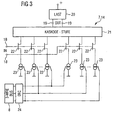
- FIG. 3 shows by way of example the structure of a programmable Amplifier with a variety of independently zuund switchable amplifier branches, the first and / or second programmable amplifier 7, 14 in the transmission arrangements can be used advantageously according to Figures 1 and 2.
- the programmable amplifier according to FIG 3 which is constructed in symmetrical circuit technology, a signal input 18 and a signal output 19 to which a electrical load 20 is connected.
- the amplifier includes three parallel-connected, symmetrical amplifier branches, each of a series circuit of a cascode stage 21, a field effect transistor 22 and a power source 23 are formed.
- the transistors 22 are each in pairs assigned to each other and paired at their control inputs connected to the signal input 18.
- the current sources 23 are also in pairs assigned to each other and each have Control inputs for switching on and off of the power sources 23 in pairs independently, with the control unit 8 are coupled.
- the control unit 8 stops value-discrete, digital signal for gain control via a three-wire bus ready.
- 22, 23 can be provided as many amplifier branches
- 16 amplifier branch pairs 21, 22, 23 already explained at the beginning allows the shutdown for the current transmission power not required amplifier branches a significant power reduction of the transmission arrangement and thus when using the transmission arrangement in portable mobile devices a significantly longer battery life or Talk time.
Landscapes
- Transmitters (AREA)
Description
Die vorliegende Erfindung betrifft eine Sendeanordnung für eine zeitkontinuierliche Datenübertragung.The present invention relates to a transmission arrangement for a continuous-time data transmission.
Während bei Mobilfunkgeräten der zweiten Generation nicht zeitkontinuierlich, sondern in Zeitfenstern, sogenannten Bursts, gesendet wird, verwenden moderne Übertragungsverfahren, beispielsweise gemäß Universal Mobile Telecommunications System(UMTS)-Standard, zeitkontinuierliche Übertragungsverfahren.While not with second-generation mobile phones time-continuous, but in time windows, so-called Bursts being sent use modern transmission methods, for example, according to Universal Mobile Telecommunications System (UMTS) standard, continuous-time transmission method.
Im UMTS-Standard ist als Vielfachzugriffsverfahren der Einsatz von Code Division Multiple Access, CDMA, vorgesehen. Dabei muß der Mobilfunksender in der Lage sein, ohne Unterbrechung zeitkontinuierlich zu senden. Derartige Mobilfunkgeräte müssen zudem sehr strengen Anforderungen an den Regelungsbereich der Sendeleistung und damit den Regelungsbereich der Leistungsverstärker sowie außerdem der Genauigkeit der Verstärkungsregelung genügen. Dadurch unterscheiden sie sich signifikant von den bisher, beispielsweise bei GSM, Global System for Mobile Communication, eingesetzten Kombinationen von Zeit- und Frequenzvielfachzugriffsverfahren, englisch TDMA, Time Division Multiple Access, und FDMA, Frequency Division Multiple Access.In the UMTS standard is the use as a multiple access method provided by Code Division Multiple Access, CDMA. there the mobile radio transmitter must be able to operate without interruption to send continuously. Such mobile devices also have very strict requirements for the regulatory area the transmission power and thus the regulatory range of Power amplifier and also the accuracy of the gain control suffice. As a result, they differ significantly from the past, for example, GSM, Global System for Mobile Communication, used combinations of Time and Frequency Division Multiple Access Method, English TDMA, Time Division Multiple Access, and FDMA, Frequency Division Multiple access.
UMTS-Mobilfunkgeräte müssen in der Lage sein, die Sendeleistung während einer Datenübertragung laufend an die sich ändernden Gegebenheiten anzupassen. Die Sendeleistung kann dabei von der aktuellen Empfangsfeldstärke des Mobilteils abhängen oder von einer Feststation vorgegeben werden.UMTS mobile devices must be capable of transmitting power during a data transmission continuously to the changing Adapt conditions. The transmission power can depend on the current receive field strength of the handset or be specified by a base station.
Da bei derartigen CDMA-Geräten zusätzlich zur Leistungsregelung während einer laufenden Datenübertragung bestimmte Anforderungen an die Größe von Fehlervektoren und an das Sendefrequenzspektrum über den gesamten, dynamischen Bereich hinweg zu erfüllen sind, weisen derzeit bekannte Mobilfunkgeräte, die für zeitkontinuierliche Datenübertragung ausgelegt sind, eine automatische Verstärkungsregelung, Automatic Gain Control, AGC, auf, welche sich dadurch auszeichnet, daß das Steuersignal für die verwendeten AGC-Bauteile ein wertkontinuierliches Analogsignal ist. Somit ist sichergestellt, daß die Sendeleistung während des ununterbrochenen Sendebetriebs nachgeregelt werden kann, ohne Grenzwerte der jeweiligen Standards zu verletzen.As with such CDMA devices in addition to power control certain requirements during an ongoing data transfer to the size of error vectors and to the transmit frequency spectrum across the entire dynamic range have to be met, currently known mobile devices, designed for continuous-time data transmission are, an automatic gain control, automatic gain Control, AGC, which is characterized in that the Control signal for the AGC components used a continuous value Analog signal is. This ensures that the transmission power during uninterrupted transmission can be readjusted, without limits of the respective Violate standards.
Die Ansteuerung derartiger AGC-Bauteile hat jedoch den Nachteil eines verhältnismäßig großen Strombedarfs für die erforderlichen Digital/Analog-Wandler, erfordert zusätzliche Chipfläche, führt zu verhältnismäßig großer Störanfälligkeit der analogen Steuersignale und bedeutet damit insgesamt verhältnismäßig hohe Kosten für den Entwurf und die Fertigung derartiger Geräte.However, the control of such AGC components has the disadvantage a relatively high electricity demand for the required Digital / analog converter, requires additional Chip area leads to relatively high susceptibility to interference the analog control signals and thus means a total of relatively high costs for the design and the production such devices.
In der Druckschrift US 5,708,681 ist ein Funk-Sende-Empfänger angegeben, bei dem im Sendezweig ein Leistungsverstärker vorgesehen ist, der einem Quadratur-Modulator nachgeschaltet ist. Die Sendeleistung wird über einen Steuerblock beeinflusst, der die Verstärkung des Leistungsverstärkers steuert in Abhängigkeit von einem digital vorliegenden Steuersignal.In the document US 5,708,681 is a radio transceiver specified, in which provided in the transmitting branch, a power amplifier is downstream of a quadrature modulator is. The transmission power is influenced by a control block, which controls the gain of the power amplifier in response to a digital control signal.
Aufgabe der vorliegenden Erfindung ist es, eine Sendeanordnung für eine zeitkontinuierliche Datenübertragung anzugeben, welche für UMTS geeignet und bezüglich der Stromaufnahme verbessert ist.The object of the present invention is a transmission arrangement for a time-continuous data transmission, which is suitable for UMTS and improved in terms of power consumption is.
Erfindungsgemäß wird die Aufgabe gelöst durch eine Sendeanordnung für zeitkontinuierliche Datenübertragung, aufweisend
- eine Basisband-Signalverarbeitungseinheit, ausgelegt für komplexwertige Signalverarbeitung, mit einem Inphase- und einem Quadratur-Signalpfad,
- einen Quadratur-Modulator mit einem ersten Eingang, der mit dem Inphase-Signalpfad gekoppelt ist, mit einem zweiten Eingang, der mit dem Quadratur-Signalpfad gekoppelt ist, und mit einem Ausgang,
- einen Hochfrequenzzweig, der mit dem Ausgang des Quadratur-Modulators gekoppelt ist,
- eine Steuereinheit, die ein wertdiskretes Steuersignal zur Beeinflussung der Sendeleistung der Sendeanordnung bereitstellt,
- einen ersten programmierbaren Verstärker, der in der Basisband-Signalverarbeitungseinheit zur Verstärkung des zu sendenden Nutzsignals mit einem einstellbaren Verstärkungsfaktor angeordnet ist, mit einem Steuereingang, der mit der Steuereinheit zur Übermittlung des wertdiskreten Steuersignals gekoppelt ist, umfassend einen im Inphase-Signalpfad angeordneten Teilverstärker und einen im Quadratur-Signalpfad angeordneten Teilverstärker, und
- einen zweiten programmierbaren Verstärker, der im Hochfrequenzzweig angeordnet ist, umfassend einen Steuereingang, der mit der Steuereinheit zur Übermittlung eines wertdiskreten Steuersignals gekoppelt ist, und
- einen Rückkopplungspfad umfassend ein Mittel zur Trägerfrequenzunterdrückung , mit einem Eingang, der mit dem Ausgang des Quadratur-Modulators gekoppelt ist, und mit einem Ausgang, der mit dem Inphase- und mit dem Quadratur-Signalpfad gekoppelt ist.
- a baseband signal processing unit, designed for complex-valued signal processing, with an in-phase and a quadrature signal path,
- a quadrature modulator having a first input coupled to the in-phase signal path, a second input coupled to the quadrature signal path, and an output;
- a radio frequency branch coupled to the output of the quadrature modulator,
- a control unit which provides a value-discrete control signal for influencing the transmission power of the transmission arrangement,
- a first programmable amplifier, which is arranged in the baseband signal processing unit for amplifying the useful signal to be transmitted with an adjustable amplification factor, with a control input, which is coupled to the control unit for transmitting the discrete-value control signal comprising a arranged in the in-phase signal path sub-amplifier and a arranged in the quadrature signal path sub-amplifier, and
- a second programmable amplifier, which is arranged in the high-frequency branch, comprising a control input, which is coupled to the control unit for transmitting a value-discrete control signal, and
- a feedback path comprising means for carrier frequency rejection, having an input coupled to the output of the quadrature modulator, and having an output coupled to the in-phase and quadrature signal paths.
Der Gegenstand des Anspruchs 1 dadurch unterscheidet von US-A-5 708 681 dadurch, daß vor dem Quadratur-Modulator eine aktive Verstärkung durchgeführt wird, und in einem Rückkopplungspfad ein Mittel zur Trägerfrequenzunterdrückung vorgesehen ist, mit einem Eingang, der mit dem Ausgang des Quadratur- Modulators gekoppelt ist, und mit einem Ausgang, der mit dem Inphase-und mit dem Quadratur-Signalpfad gekoppelt ist. The subject matter of claim 1 thereby distinguishes from US-A-5,708,681 in that an active amplification is performed in front of the quadrature modulator, and in a feedback path means for carrier frequency rejection is provided with an input connected to the output of the quadrature modulator is coupled, and with an output that with the inphase and with the Quadrature signal path is coupled.
Gemäß vorliegendem Prinzip wird zur Beeinflussung der Sendeleistung der Sendeanordnung zumindest ein programmierbarer Verstärker eingesetzt, der mit einem wertdiskreten Steuersignal angesteuert wird. Im Unterschied zu den üblicherweise verwendeten Automatic Gain Control(AGC)-Reglern, welche mit wertkontinuierlichen Analogsignalen zur Verstärkungsregelung angesteuert werden, erfolgt bei dem vorliegenden, programmierbaren Verstärker die Ansteuerung mit einem wertdiskreten Steuersignal für die Regelung der Amplitudenverstärkung in der Sendeanordnung.According to the present principle is to influence the transmission power the transmission arrangement at least one programmable Amplifier used with a discrete-value control signal is controlled. Unlike the usual used automatic gain control (AGC) controllers, which with continuous-value analog signals for gain control be controlled, takes place at the present, programmable Amplifier control with a value discrete Control signal for the regulation of the amplitude amplification in the transmission arrangement.
Gemäß der vorliegenden Erfindung ist des weiteren eine Rückkopplungsschleife zur Trägerfrequenzunterdrückung vorgesehen, mit einem Rückkopplungspfad, der den Ausgang des Quadratur-Modulators mit seinem Inphase- und seinem Quadratur-Signaleingang koppelt. Eine derartige Rückkopplungsschleife kann beispielsweise Frequenzanteile bei der Trägerfrequenz, welche als Störsignale am Ausgang des Modulators auftreten, in ihrer Amplitude detektieren und auf die am Eingang des Quadratur-Modulators zuführbaren Signalkomponenten bezüglich von Gleichspannungsoffsets zwischen den symmetrischen Komponenten in Inphase-Zweig und /oder Quadratur-Zweig so einwirken, daß die Trägerfrequenz verschwindet oder möglichst gering ist.According to the present The invention is further a feedback loop for carrier frequency rejection provided with a feedback path, the output of the quadrature modulator with its inphase and its quadrature signal input. Such Feedback loop can, for example, frequency components at the carrier frequency, which as noise at the output of the modulator occur in their amplitude detect and to the feedable at the input of the quadrature modulator Signal components with respect to DC offset between the symmetric components in in-phase branch and / or Quadrature branch act so that the carrier frequency disappears or is as small as possible.
Dem vorliegenden Prinzip zum Aufbau einer Sendeanordnung für zeitkontinuierliche Datenübertragung liegt die Erkenntnis zugrunde, daß bei der zeitkontinuierlichen Datenübertragung bei gleichzeitiger Erfüllung von Spezifikationsgrenzwerten, insbesondere in Bezug auf das hochfrequente Spektrum und die Größe von Fehlervektoren, dennoch auf eine wertkontinuierlich angesteuerte, automatische Verstärkungsregelung verzichtet werden kann.The present principle for establishing a transmission arrangement for continuous-time data transmission is based on the knowledge that at the time-continuous data transmission at simultaneous fulfillment of specification limits, in particular in terms of high-frequency spectrum and the Size of error vectors, yet on a continuous value controlled, automatic gain control omitted can be.
Da in den digitalen Signalprozessoren im Basisband einer derartigen Sendeanordnung ohnehin üblicherweise die Steuerspannung für die Verstärkungsregelung digital, das heißt zeitund wertdiskret vorliegt, kann mit vorliegendem Prinzip vorteilhafterweise auf Digital/Analog-Wandler verzichtet werden. Ein derartiges Spannungssignal wird in der Basisband-Signalverarbeitungseinheit üblicherweise in Abhängigkeit von der aktuellen Empfangsfeldstärke, dem sogenannten Received Signal Strength Indicator, RSSI, abgeleitet. Mit dem D/A-Wandler können auch nachgeschaltete Filter zur Rekonstruktion des analogen Steuersignals entfallen.As in the digital signal processors in the baseband of such Transmission arrangement usually the control voltage anyway for the gain control digital, that is time and discrete value present, can advantageously with the present principle to dispense with digital / analog converter. Such a voltage signal is in the baseband signal processing unit usually depending on the current reception field strength, the so-called received signal Strength Indicator, RSSI derived. With the D / A converter can also use downstream filters to reconstruct the omitted analog control signal.
Das Entfallen der D/A-Wandler bringt einen signifikant geringeren Strombedarf mit sich sowie zusätzlich eine deutliche Verringerung der benötigten Chipfläche für die Basisband-Signalverarbeitungseinheit, die beispielsweise in einem Basisband-IC (Integrated Circuit) integriert sein kann.The elimination of the D / A converter brings a significantly lower Electricity demand with and in addition a clear Reduction of the required chip area for the baseband signal processing unit, for example, in a baseband IC (Integrated Circuit) can be integrated.
Das digitale Datenformat des Steuersignals hat den zusätzlichen Vorteil, daß eine Verbesserung der Störanfälligkeit gegenüber einem Analogsignal erzielt ist.The digital data format of the control signal has the additional Advantage that an improvement in the susceptibility to an analog signal is achieved.
Bei geeigneter Auslegung kann auch die Genauigkeit der Sendeleistungsregelung, beispielsweise in einem Mobilteil, in dem die Sendeanordnung vorgesehen ist, deutlich erhöht werden. Mit der gemäß vorliegendem Prinzip möglichen, ausschließlich digitalen Signalverarbeitung des Steuersignals zur Beeinflussung der Sendeleistung, beispielsweise in Abhängigkeit von der aktuellen Empfangsfeldstärke und von Vorgabesignalen einer Basisstation, ist dieses Steuersignal unempfindlich gegenüber Temperatureinflüssen, Substrat-Rauschen, welches die D/A-Konverter beeinflussen würde, Schwankungen der Betriebsspannung sowie Fertigungsschwankungen. Bei einem für komplexwertige Signalverarbeitung ausgelegten Sender, bei dem die Anforderungen an die Paarungstoleranzen der in den komplementären Signalzweigen verwendeten Bauteile sehr hoch sind, ist ein zusätzlicher Vorteil durch Einsetzen einer wertdiskreten Ansteuerung des programmierbaren Verstärkers erzielt.With a suitable design, the accuracy of the transmission power control, For example, in a handset in which the transmission arrangement is provided, be increased significantly. With the according to the present principle possible, exclusively digital signal processing of the control signal for influencing the transmission power, for example, depending on the current receive field strength and default signals of a Base station, this control signal is insensitive to Temperature influences, substrate noise, which the D / A converter would affect fluctuations in the operating voltage as well as manufacturing fluctuations. One for complex valued Signal processing designed transmitter in which the requirements for mating tolerances in the complementary Signal branches used components very high is an added benefit by inserting a Discrete-value control of the programmable amplifier achieved.
Schließlich führen die vorteilhaften Eigenschaften des vorliegenden Prinzips wie Reduzierung der Chipfläche, Erhöhung der Robustheit gegenüber Interferenzen und anderen Umwelteinflüssen, die Reduzierung der Zahl der erforderlichen Pins an den ICs sowie die Leistungsreduzierung zusätzlich zu einer deutlichen Kostenreduzierung. Diese wiederum begünstigt die im vorliegenden Segment übliche Massenherstellung.Finally, the advantageous properties of the present result Principles like reduction of chip area, increase the robustness against interference and other environmental influences, the reduction in the number of required pins the ICs and the power reduction in addition to a significant cost reduction. This in turn favors the in the present segment usual mass production.
Gemäß dem beschriebenen Prinzip ist neben dem als erstem programmierbaren Verstärker ausgeführten programmierbaren Verstärker ein zusätzlicher zweiter programmierbarer Verstärker vorgesehen, von denen je einer in der Basisband-Signalverarbeitungseinheit und einer im Hochfrequenzzweig angeordnet ist. Der im Basisband angeordnete, erste programmierbare Verstärker ist dabei selbstverständlich sowohl im Inphase- als auch im Quadratur-Signalzweig vorgesehen.According to the described principle is next to the first programmable Amplifier implemented programmable amplifier an additional second programmable amplifier provided, one each in the baseband signal processing unit and one arranged in the high-frequency branch is. The base band, the first programmable amplifier is of course both in-phase as also provided in the quadrature signal branch.
Die beschriebenen, programmierbaren Verstärker werden jeweils mit einem wertdiskreten Steuersignal angesteuert.The described, programmable amplifiers are each controlled with a discrete-value control signal.
Die Verteilung der Signalverstärkung auf Basisband und Hochfrequenzzweig ermöglicht eine besonders große Flexibilität bei der Auslegung der Verstärkungsstufen und bei der Anpassung des Timings. Zusätzlich ergibt sich mit Vorteil die Möglichkeit, Basisband-ICs und Hochfrequenz-ICs verschiedener Typen oder Hersteller kombinieren zu können.The distribution of signal amplification on baseband and high frequency branch allows a particularly high flexibility in the design of the amplification stages and in the adaptation of the timing. In addition, there is the advantage of being able to Baseband ICs and high-frequency ICs of various types To be able to combine types or manufacturers.
Da gemäß UMTS-Spezifikation mit Klasse 3-Geräten ein Verstärkungs-Regelungsbereich
im Sender von mindestens 74 dB vorgesehen
ist, kann dieser hohe Dynamikbereich vorteilhafterweise
auf zwei Verstärkerstufen, je eine im Basisband und im Hochfrequenzzweig
angeordnet, verteilt werden.Because according to UMTS specification with
Bevorzugt kann in demjenigen, programmierbaren Verstärker, der im Basisband angeordnet ist, eine Verstärkung von mit einem Dynamikumfang von 20 bis 30 dB erfolgen, während die Verstärkung im Hochfrequenzzweig bevorzugt einen Dynamikumfang von 50 bis 60 dB hat.Preferably, in that, programmable amplifier, which is arranged in the baseband, a gain of one Dynamic range of 20 to 30 dB, while the gain in the high-frequency branch preferably a dynamic range from 50 to 60 dB.
Die Sendeanordnung kann bevorzugt in der Basisband-Signalverarbeitungseinheit oder im Hochfrequenz-Zweig einen passiven, programmierbaren Verstärker aufweisen, mit einem Steuereingang, der mit der Steuereinheit zur Bereitstellung einer wertdiskreten Signaldämpfung gekoppelt ist.The transmission arrangement may preferably be in the baseband signal processing unit or in the high-frequency branch one passive, programmable amplifier, with a Control input to the control unit to provide a discrete-value signal attenuation is coupled.
Der passive, programmierbare Verstärker kann als Widerstandsnetzwerk ausgeführt sein.The passive, programmable amplifier can be used as a resistor network be executed.
Der passive, programmierbare Verstärker dämpft das zu sendende Signal. Die Dämpfung ist dabei in wertdiskreten Schritten einstellbar. Mit einer derartigen, passiven Regelung ist eine Reduzierung der Stromaufnahme sowie ein lediglich geringes Substratrauschen ohne Verringerung des Dynamikbereichs des Senders erzielbar.The passive, programmable amplifier attenuates the signal to be sent Signal. The damping is in discrete-value steps adjustable. With such a passive control is a Reduction of power consumption and a low Substrate noise without reducing the dynamic range of the Transmitter achievable.
Der passive, programmierbare Verstärker ist bevorzugt am Ausgang des Quadratur-Modulators angeschlossen.The passive, programmable amplifier is preferably at the output connected to the quadrature modulator.
Der passive, programmierbare Verstärker am Ausgang des Quadratur-Modulators ist bevorzugt einem aktiven, programmierbaren Verstärker vorgeschaltet.The passive, programmable amplifier at the output of the quadrature modulator is preferably an active, programmable Amplifier upstream.
Bevorzugt ist der passive, programmierbare Verstärker in Schritten von 6 dB einstellbar. Der erste, aktive, programmierbare Verstärker in der Basisband-Signalverarbeitungseinheit ist bevorzugt in Schritten von 1 dB einstellbar. Der zweite, aktive, programmierbare Verstärker im Hochfrequenz-Zweig ist bevorzugt in Schritten von 6 dB einstellbar.Preferably, the passive, programmable amplifier is in Adjustable steps of 6 dB. The first, active, programmable Amplifier in the baseband signal processing unit is preferably adjustable in increments of 1 dB. Of the second, active, programmable amplifiers in the high-frequency branch is preferably adjustable in steps of 6 dB.
Um den Strombedarf der Sendeanordnung weiter zu verringern, umfaßt der programmierbare Verstärker mehrere, parallel geschaltete und unabhängig voneinander zu- und abschaltbare Verstärkerzweige, wobei das Zu- und Abschalten der Verstärkerzweige in Abhängigkeit von dem wertdiskreten Steuersignal erfolgt.To further reduce the power consumption of the transmission device, the programmable amplifier comprises several, in parallel and independently switched on and off Amplifier branches, wherein the switching on and off of the amplifier branches depending on the value discrete control signal he follows.
Die jeweils nicht benötigten Verstärkerzweige können abgeschaltet, das heißt deren Stromquellen deaktiviert werden, so daß der Strombedarf des programmierbaren, aktiven Verstärkers oder der programmierbaren Verstärker sinkt. Da normalerweise eine Sendeanordnung, beispielsweise im Mobilfunk, den Großteil der Betriebszeit nicht mit maximaler Sendeleistung arbeitet, ist mit der beschriebenen Aufteilung des programmierbaren Verstärkers auf mehrere, unabhängig voneinander zu- und abschaltbare Zweige, eine deutliche Reduzierung der Stromaufnahme möglich.The respectively not required amplifier branches can be switched off, that is, their power sources are disabled, so that the power requirement of the programmable, active amplifier or the programmable amplifier drops. As usual a transmission arrangement, for example in mobile communications, the majority the operating time does not work with maximum transmission power, is with the described division of the programmable Amplifier on several, independently from each other and switchable branches, a significant reduction in power consumption possible.
Gemäß einer weiteren, bevorzugten Ausführungsform der vorliegenden Erfindung weist der programmierbare Verstärkung ein Mittel zum Einstellen der Anstiegszeit des Verstärkungsfaktors auf.According to a further preferred embodiment of the present invention Invention includes the programmable gain Means for adjusting the rise time of the gain on.
Das Mittel zum Einstellen der Anstiegszeit ermöglicht, daß beim Umschalten des programmierbaren Verstärkers von einer Verstärkerstufe auf eine andere Verstärkerstufe kein sprunghaftes Verändern des Verstärkungsfaktors erfolgt, sondern ein weicher Übergang möglich ist. Hierdurch werden unerwünschte, hochfrequente Signalanteile beim Umschalten deutlich verringert und zudem auch die Amplitude des Fehlervektors beim Umschalten verringert. The means for adjusting the rise time allows when switching the programmable amplifier from one Amplifier stage on another amplifier stage no jumpy Changing the gain takes place, but a soft transition is possible. This will cause unwanted, High frequency signal components when switching significantly reduced and also the amplitude of the error vector when switching reduced.
Das Steuersignal zum Ansteuern eines derart weitergebildeten, programmierbaren Verstärkers ist dabei weiterhin ein wertdiskretes Steuersignal.The control signal for driving such a further developed, Programmable amplifier is still a value discrete Control signal.
Die Sendeanordnung ist bevorzugt in einem Mobilfunksender vorgesehen.The transmission arrangement is preferred in a mobile radio transmitter intended.
Weitere Einzelheiten und vorteilhafte Ausgestaltungen der vorliegenden Erfindung sind Gegenstand der Unteransprüche.Further details and advantageous embodiments of Present invention are the subject of the dependent claims.
Nachfolgend wird die Erfindung an mehreren Ausführungsbeispielen anhand der Zeichnungen näher erläutert.The invention will be described below with reference to several embodiments explained in more detail with reference to the drawings.
Es zeigen:
- Figur 1
- ein vereinfachtes Blockschaltbild mit ausgewählten Bauteilen einer Sendeanordnung,
Figur 2- eine Weiterbildung der Sendeanordnung von Figur 1 mit Trägerfrequenzunterdrückung gemäß vorliegendem Prinzip, und
Figur 3- ein vereinfachtes Schaltbild eines beispielhaften,
programmierbaren Verstärkers zum Einsatz in Sendeanordnungen
gemäß Figuren 1
oder 2.
- FIG. 1
- a simplified block diagram with selected components of a transmission arrangement,
- FIG. 2
- a development of the transmission arrangement of Figure 1 with carrier frequency suppression according to the present principle, and
- FIG. 3
- a simplified circuit diagram of an exemplary programmable amplifier for use in transmission arrangements according to Figures 1 or 2.
Figur 1 zeigt eine Sendeanordnung ausgelegt für zeitkontinuierliche
Datenübertragung. Diese umfaßt eine Basisband-Signalverarbeitungseinheit
1, einen Quadraturmodulator 2 und
einen Hochfrequenzzweig 3. Die Basisband-Signalverarbeitungseinheit
1 ist für komplexwertige Signalverarbeitung ausgelegt
und umfaßt hierfür einen Inphase-Zweig 4 und einen Quadratur-Signalpfad
5. Inphase- und Quadratur-Signalpfad 4, 5 sind jeweils
zur Übertragung symmetrischer Signale ausgebildet. Inphase-
und Quadratur-Signalpfad 4, 5 weisen je ein TiefpaßFilter
6 auf, denen je ein erster programmierbarer Verstärker
7 nachgeschaltet ist. Die ersten programmierbaren Verstärker
7 weisen je einen Steuereingang zum Zuführen eines
wertdiskreten Steuersignals auf, der mit dem Ausgang einer
Steuereinheit 8 über einen digitalen Dreileiterbus gemäß der
3Wire-Bus-Spezifikation verbunden ist. An die Ausgänge der
ersten programmierbaren Verstärker 7 ist ein Quadratur-Modulator
2 angeschlossen. Der Quadratur-Modulator 2 umfaßt
zwei Gilbert-Multiplizierer 9, die mit ihrem ersten Eingangspaar
mit je einem Ausgang je eines ersten programmierbaren
Verstärkers 7 verbunden sind und deren zweites Eingangspaar
über einen 0 Grad/90 Grad-Frequenzteiler 10 an einen spannungsgesteuerten
Oszillator 11 zur Bereitstellung eines komplexwertigen
Signals mit einer Trägerfrequenz angeschlossen
ist. Die Ausgänge der beiden Gilbert-Multiplizierer 9 sind an
je ein Eingangspaar eines Summierknotens 12 angeschlossen,
dessen Ausgang den Ausgang des Quadratur-Modulators 2 bildet.
An den Ausgang des Quadratur-Modulators 2 ist der Hochfrequenzzweig
3 angeschlossen, der einen passiven, programmierbaren
Verstärker 13, einen zweiten programmierbaren Verstärker
14, ein Bandpaßfilter 15 und einen Leistungsverstärker 16
umfaßt. Der Leistungsverstärker 16 weist einen Ausgang auf,
der zugleich den Ausgang des Hochfrequenz-Zweiges 3 bildet
und der an eine Antenne 17 angekoppelt ist. Der passive, programmierbare
Verstärker 13 ist mit seinem Eingang an den symmetrisch
ausgebildeten Ausgangs des Summierknotens 12 angeschlossen.
Der Ausgang des passiven, programmierbaren Verstärkers
13 ist mit dem Eingang des zweiten programmierbaren
Verstärkers 14, der ein aktiver Verstärker ist, verbunden. An
den Ausgang des zweiten programmierbaren Verstärkers 14 ist
ein Bandpaßfilter 15 angeschlossen. Der Ausgangs des Bandpaßfilters
15 ist mit einem Eingang des Leistungsverstärkers 16
gekoppelt. Sowohl der passive, programmierbare Verstärker 13,
als auch der zweite programmierbare Verstärker 14 sind zu ihrer
Steuerung mit der Steuereinheit 8 über den Drei-Leiter-Bus
verbunden.FIG. 1 shows a transmission arrangement designed for continuous-time transmission
Data transfer. This comprises a baseband signal processing unit
1, a
Die beschriebene Sendeanordnung für zeitkontinuierliche Datenübertragung ist demnach als Homodyn-Sender oder Direktumsetzer ausgebildet.The described transmission arrangement for continuous-time data transmission is therefore as a homodyne transmitter or direct converter educated.
Die Ansteuerung der programmierbaren Verstärker 7, 13, 14
durch die Steuereinheit 8 erfolgt mittels wertdiskreter Signale.
Die Sendeanordnung ist für eine zeitkontinuierliche
Datenübertragung gemäß CDMA ausgelegt und als UMTS-Sender
ausgebildet. Bei derartigen Mobilfunkgeräten gemäß UMTS-Standard
ist normalerweise neben dem gezeigten Sendezweig zusätzlich
ein in Figur 1 nicht dargestellter Empfangszweig zur
Bildung eines Transceivers vorgesehen.The control of the
Die gesamte, regelbare Verstärkung der Sendeanordnung ist zum
Erzielen eines großen Dynamikumfangs auf zwei aktive, programmierbare
Verstärkerstufen 7, 14 und eine passive, programmierbare
Verstärkerstufe 13 verteilt. Dabei wird in der
Basisband-Signalverarbeitungseinheit 1 eine Verstärkungsregelung
im Umfang von ca. 20 bis 30 dB erzielt, während im Hochfrequenz-Zweig
3 ein Dynamikumfang von ca. 50 bis 60 dB als
Regelbereich vorgesehen ist. Da am Ausgang des Quadratur-Modulators
vorteilhafterweise ein Leistungspegel von ca. -10
dBm vorherrschen soll, muß am Ausgang des Quadratur-Modulators
2 ein Verstärkungsregelungsbereich von ca. +15 bis -45
dB vorgesehen sein. Dies erlaubt mit Vorteil die Verwendung
einer passiven, programmierbaren Verstärkungsstufe 13, welche
im vorliegenden Ausführungsbeispiel als steuerbares Widerstandsnetzwerk
ausgeführt ist. Im beschriebenen Ausführungsbeispiel
sind der passive, programmierbare Verstärker 13 und
der zweite programmierbare Verstärker 14 jeweils in Schritten
von 6 dB verstellbar. Der erste programmierbare Verstärker 7
im Basisband ist in diskreten Schritten von 1 dB verstellbar.
Die Verstärkungsfaktoren der Verstärker 7, 13, 14 sind also
nicht, wie üblicherweise bei kontinuierlichen Datenübertragungssystemen
vorgesehen, wertkontinuierlich, sondern wertdiskret
einstellbar. Durch die beschriebene Kombination von
Basisband- und Hochfrequenz-Verstärkungsregelung kann insgesamt
eine Auflösung der Verstärkungsregelung von 1 dB durch
geeignete Ansteuerung Verstärker 7, 13, 14 mittels der Steuereinheit
8 und wertdiskreten Steuersignalen erzielt werden.The total, controllable amplification of the transmission arrangement is for
Achieve a large dynamic range on two active, programmable
Amplifier stages 7, 14 and a passive,
Trotz der wertdiskreten Verstärkungsregelung ist es mit vorliegender
Sendeanordnung möglich, die bei CDMA-Sendern vorgeschriebenen
Anforderungen bezüglich des hochfrequenten Spektralgehalts
der Sendesignale und der erforderlichen Größe der
Fehlervektoren einzuhalten. Dies wird dadurch noch erleichtert,
daß die programmierbaren Verstärker 13, 14 eine einstellbare
Anstiegszeit bezüglich ihrer Impulse haben. Die Anstiegszeit
im Basisband ist inhärent länger, wenn Basisbandfilter
vorgesehen sind. Im Hochfrequenzzweig jedoch ist eine
steuerbare Anstiegszeit derart vorgesehen, daß diese mit der
Anstiegszeit der Verstärker im Basisband übereinstimmt. Somit
ist insgesamt ein problemloses Erfüllen der bei UMTS auf
17,5% begrenzten Fehlervektorgröße ermöglicht.Despite the discrete-value gain control, it is present with
Transmission arrangement possible, prescribed by CDMA stations
Requirements regarding the high-frequency spectral content
the transmission signals and the required size of
To comply with error vectors. This will be made even easier
that the
Die Sendeanordnung gemäß beschriebenem Ausführungsbeispiel ist sowohl in Mobilfunksystemen der zweiten Mobilfunkgeneration mit CDMA, der dritten Generation sowie außerdem in kommenden Generationen von Mobilfunksystemen, wie beispielsweise der geplanten vierten Generation, einsetzbar. The transmission arrangement according to the described embodiment is both in mobile radio systems of the second mobile generation with CDMA, the third generation and also in coming Generations of mobile systems, such as the planned fourth generation.
Figur 2 zeigt eine Weiterbildung der Sendeanordnung von Figur
1 mit einer zusätzlichen Vorrichtung zur Trägerfrequenzunterdrückung
18, die den Ausgang des Quadratur-Modulators 2
mit seinen Quadratur-Eingängen koppelt. Abgesehen von dieser
Weiterbildung entspricht die Sendeanordnung von Figur 2 in
ihren verwendeten Bauteilen, deren Zusammenschaltung, ihren
Funktionen und dem vorteilhaften Zusammenwirken der Bauteile
der Sendeanordnung von Figur 1, deren Beschreibung daher an
dieser Stelle nicht wiederholt wird.FIG. 2 shows a development of the transmission arrangement of FIG
1 with an additional device for
Die zusätzliche Schleife zur Trägerfrequenzunterdrückung umfaßt
einen Rückkopplungspfad, der das Mittel zur Trägerfrequenzunterdrückung
18 umfaßt und der mit seinem symmetrisch
ausgebildeten Eingang an den Ausgang des Summierknotens 12
angeschlossen ist. Am Ausgang des Mittels zur Trägerunterdrückung
18 sind zwei Ausgangsklemmenpaare vorgesehen, die
jeweils mit den Eingängen der Gilbert-Mischer 9 an deren symmetrischen
Eingangspaaren gekoppelt sind, beispielsweise wie
in Figur 2 dargestellt mittels Addierknoten, die an weiteren
Eingängen mit den Ausgängen der programmierbaren Verstärker 7
verbunden sind.The additional loop for carrier frequency rejection comprises
a feedback path containing the means for
Das Mittel zur Trägerfrequenzunterdrückung 18 detektiert gegebenenfalls
am Ausgang des Quadratur-Modulators 2 durchscheinende
Anteile der vom VCO 11 bereitgestellten Trägerfrequenz,
englisch Carrier Frequency, und beeinflußt in deren
Abhängigkeit die Inphase- und Quadratur-Komponenten der Basisbandsignale
in den Signalpfaden 4 und 5. Dabei kann beispielsweise
ein zusätzlicher Gleichspannungsoffset innerhalb
der Symmetriekomponenten von Inphase-Zweig 4 oder innerhalb
der Symmetriekomponenten von Quadratur-Zweig 5 oder beiden
eingeführt werden.The means for
Das Vorsehen einer Trägerfrequenzunterdrückungsschleife ist
insbesondere in Kombination mit den programmierbaren Verstärkern
7 vorteilhaft, welche gegebenenfalls zu einem verstärkten
Auftreten von Frequenzanteilen bei der Trägerfrequenz am
Ausgang des Quadratur-Modulators 2 führen können.The provision of a carrier frequency rejection loop is
especially in combination with the
Figur 3 zeigt beispielhaft den Aufbau eines programmierbaren
Verstärkers mit einer Vielzahl von unabhängig voneinander zuund
abschaltbaren Verstärkerzweigen, der als erster und/oder
zweiter programmierbarer Verstärker 7, 14 in den Sendeanordnungen
gemäß Figuren 1 und 2 mit Vorteil einsetzbar ist.FIG. 3 shows by way of example the structure of a programmable
Amplifier with a variety of independently zuund
switchable amplifier branches, the first and / or
second
Im Einzelnen umfaßt der programmierbare Verstärker gemäß Figur
3, der in symmetrischer Schaltungstechnik aufgebaut ist,
einen Signaleingang 18 und einen Signalausgang 19, an dem eine
elektrische Last 20 angeschlossen ist. Der Verstärker umfaßt
drei parallel geschaltete, symmetrische Verstärkerzweige,
die jeweils von einer Serienschaltung aus einer Kaskode-Stufe
21, einem Feldeffekttransistor 22 und einer Stromquelle
23 gebildet sind. Die Transistoren 22 sind jeweils paarweise
einander zugeordnet und an ihren Steuereingängen paarweise
mit dem Signaleingang 18 verbunden. Die Stromquellen 23 sind
ebenfalls paarweise einander zugeordnet und weisen jeweils
Steuereingänge zum Zu- und Abschalten der Stromquellen 23
paarweise unabhängig voneinander auf, die mit der Steuereinheit
8 gekoppelt sind. Die Steuereinheit 8 stellt dabei ein
wertdiskretes, digitales Signal zur Verstärkungsregelung über
einen Drei-Leiter-Bus bereit. Die Kopplung der Steuereingänge
der Stromquellen 23 mit der Steuereinheit 8 erfolgt über einen
Decoder 24, der das vom 3-Leiter-Bus an seinem Eingang
zugeführte, serielle Signal in ein paralleles Signal konvertiert,
welches an seinem Ausgang bereitsteht.In detail, the programmable amplifier according to FIG
3, which is constructed in symmetrical circuit technology,
a
Anstelle der gezeigten drei Paare von Verstärkerzweigen 21,
22, 23 können beliebig viele Verstärkerzweige vorgesehen
sein, beispielsweise 16 Verstärkerzweigpaare 21, 22, 23. Wie
bereits eingangs erläutert, ermöglicht das Abschalten der für
die aktuelle Sendeleistung nicht benötigten Verstärkerzweige
eine deutliche Stromreduzierung der Sendeanordnung und damit
bei Einsatz der Sendeanordnung in tragbaren Mobilfunkgeräten
eine deutlich längere Akku-Betriebszeit beziehungsweise
Sprechzeit.Instead of the three pairs of
Alternativ zu den in den Ausführungsbeispielen vorgesehenen Abstufung der Verstärkungs- und Dämpfungsschritten von 1 dB bzw. 6 dB kann in Abhängigkeit der Anwendung auch jede andere Kombination der Schrittweiten, solange die Schrittweite diskret abgestuft ist, vorgesehen sein. As an alternative to those provided in the exemplary embodiments Gradation of the gain and attenuation steps of 1 dB or 6 dB, depending on the application, any other Combination of step sizes, as long as the step size discrete graded, be provided.
- 11
- Basisband-SignalverarbeitungseinheitBaseband signal processing unit
- 22
- Quadratur-ModulatorQuadrature modulator
- 33
- Hochfrequenz-ZweigHigh-frequency branch
- 44
- Inphase-SignalpfadIn-phase signal path
- 55
- Quadratur-SignalpfadQuadrature signal path
- 66
- Tiefpaßfilterlow pass filter
- 77
- erster programmierbarer Verstärkerfirst programmable amplifier
- 88th
- Steuereinheitcontrol unit
- 99
- Mischermixer
- 1010
- 0 Grad / 90 Grad-Teiler0 degrees / 90 degrees divider
- 1111
- spannungsgesteuerter Oszillatorvoltage controlled oscillator
- 1212
- Summierknotensumming
- 1313
- passiver, programmierbarer Verstärkerpassive, programmable amplifier
- 1414
- zweiter programmierbarer Verstärkersecond programmable amplifier
- 1515
- Bandpaßfilterbandpass filter
- 1616
- Leistungsverstärkerpower amplifier
- 1717
- Antenneantenna
- 1818
- Signaleingangsignal input
- 1919
- Signalausgangsignal output
- 2020
- Lastload
- 2121
- Kaskode-StufeCascode stage
- 2222
- Transistortransistor
- 2323
- Stromquellepower source
- 2424
- Decoderdecoder
- II
- Inphase-SignalkomponenteIn-phase signal component
- Quadratur-SignalkomponenteQuadrature signal component
Claims (5)
- A transmission arrangement for transmitting data continuously in the time domain, having:a baseband signal processing unit (1), designed for complex-value signal processing for a useful signal which is to be transmitted, having an inphase and a quadrature signal path (4, 5),a quadrature modulator (2) having a first input, which is coupled to the inphase signal path (4), having a second input, which is coupled to the quadrature signal path (5), and having an output,a radiofrequency path (3), which is coupled to the output of the quadrature modulator (2),a control unit (8), which provides a discrete-value control signal for influencing the transmission power of the transmission arrangement,a first programmable amplifier (7), which is arranged in the baseband signal processing unit (1) in order to amplify the useful signal which is to be transmitted using an adjustable gain factor, having a control input which is coupled to the control unit (8) in order to transmit the discrete-value control signal, comprising an amplifier component which is arranged in the inphase signal path (4) and an amplifier component which is arranged in the quadrature signal path (5), anda second programmable amplifier (14), which is arranged in the radiofrequency path (3), comprising a control input which is coupled to the control unit (8) in order to transmit a discrete-value control signal, anda feedback path comprising a means for carrier frequency suppression (18), having an input which is coupled to the output of the quadrature modulator (2) and having an output which is coupled to the inphase and the quadrature signal path (4, 5).
- The transmission arrangement as claimed in claim 1,
wherein
the baseband signal processing unit (1) or the radiofrequency path (3) contains a passive, programmable amplifier (13) in order to process the useful signal which is to be transmitted, having a control input which is coupled to the control unit (8) in order to provide discrete-value signal attenuation. - The transmission arrangement as claimed in claim 1 or 2,
wherein
the first and/or the second programmable amplifier (7, 14) comprises a plurality of parallel-connected amplifier paths (21, 22, 23) which can be connected and disconnected independently of one another, the amplifier paths (21, 22, 23) being connected and disconnected on the basis of the discrete-value control signal. - The transmission arrangement as claimed in one of claims 1 to 3,
wherein
the second programmable amplifier (14) has a means for setting the rise time of the gain factor. - The transmission arrangement as claimed in one of claims 1 to 4,
wherein
the transmission arrangement is a mobile radio transmitter.
Applications Claiming Priority (3)
| Application Number | Priority Date | Filing Date | Title |
|---|---|---|---|
| DE10163466A DE10163466A1 (en) | 2001-12-21 | 2001-12-21 | Transmission arrangement for continuous data transmission |
| DE10163466 | 2001-12-21 | ||
| PCT/DE2002/004624 WO2003056739A2 (en) | 2001-12-21 | 2002-12-17 | Transmission configuration for continuous-time data transmission |
Publications (2)
| Publication Number | Publication Date |
|---|---|
| EP1456992A2 EP1456992A2 (en) | 2004-09-15 |
| EP1456992B1 true EP1456992B1 (en) | 2005-05-04 |
Family
ID=7710508
Family Applications (1)
| Application Number | Title | Priority Date | Filing Date |
|---|---|---|---|
| EP02792669A Expired - Lifetime EP1456992B1 (en) | 2001-12-21 | 2002-12-17 | Transmission configuration for continuous-time data transmission |
Country Status (5)
| Country | Link |
|---|---|
| US (1) | US7555272B2 (en) |
| EP (1) | EP1456992B1 (en) |
| JP (1) | JP3970845B2 (en) |
| DE (2) | DE10163466A1 (en) |
| WO (1) | WO2003056739A2 (en) |
Families Citing this family (13)
| Publication number | Priority date | Publication date | Assignee | Title |
|---|---|---|---|---|
| TWI260896B (en) * | 2003-04-04 | 2006-08-21 | Mediatek Inc | Wireless communication system with the device that detect transmission mode of communication signal |
| ATE372611T1 (en) * | 2003-05-09 | 2007-09-15 | Nxp Bv | METHOD AND ARRANGEMENT FOR ADJUSTING THE TRANSMIT POWER OF A MOBILE TRANSMISSION DEVICE |
| DE10361651B4 (en) * | 2003-12-30 | 2013-12-05 | Intel Mobile Communications GmbH | Method for calibrating an amplifier arrangement |
| DE102004024875B4 (en) * | 2004-05-19 | 2006-09-07 | Infineon Technologies Ag | Amplifier arrangement and method for compensating a signal component in an amplifier arrangement |
| US7664520B2 (en) * | 2004-06-24 | 2010-02-16 | Nokia Corporation | Low current direct conversion transmitter architecture |
| DE102004039830B4 (en) * | 2004-08-17 | 2007-11-08 | Infineon Technologies Ag | Amplifier circuit with adjustable discrete-value gain, use of the amplifier circuit and method for operating a discrete-value adjustable amplifier |
| US7596185B2 (en) | 2004-12-13 | 2009-09-29 | Infineon Technologies Ag | Radio transmitter with variable amplifier units in the baseband section and in the radio-frequency section of the transmission path |
| DE102004059985B4 (en) * | 2004-12-13 | 2017-11-16 | Intel Deutschland Gmbh | Radio transmitter with adjustable amplifier units in the baseband and in the high-frequency section of the transmission path |
| JP4752272B2 (en) * | 2005-01-05 | 2011-08-17 | ソニー株式会社 | Communication device |
| US8385458B2 (en) * | 2006-08-08 | 2013-02-26 | Nec Corporation | Signal processing circuit and signal processing method |
| US8315581B2 (en) | 2008-09-18 | 2012-11-20 | Intel Mobile Communications GmbH | Transmitter with hybrid closed loop power control |
| JP5564111B2 (en) * | 2010-06-22 | 2014-07-30 | ルネサスエレクトロニクス株式会社 | Semiconductor device |
| JP7176403B2 (en) * | 2018-12-26 | 2022-11-22 | 東ソー株式会社 | latex adhesive composition |
Family Cites Families (16)
| Publication number | Priority date | Publication date | Assignee | Title |
|---|---|---|---|---|
| US5029233A (en) * | 1987-10-09 | 1991-07-02 | Motorola, Inc. | Radio arrangement having two radios sharing circuitry |
| US5066923A (en) * | 1990-10-31 | 1991-11-19 | Motorola, Inc. | Linear transmitter training method and apparatus |
| US5307512A (en) | 1991-06-03 | 1994-04-26 | Motorola, Inc. | Power control circuitry for achieving wide dynamic range in a transmitter |
| US5333175A (en) * | 1993-01-28 | 1994-07-26 | Bell Communications Research, Inc. | Method and apparatus for dynamic power control in TDMA portable radio systems |
| JPH06303145A (en) | 1993-04-13 | 1994-10-28 | Fujitsu Ltd | Carrier leak suoppression circuit |
| GB2297443B (en) * | 1995-01-26 | 1999-09-08 | Sony Uk Ltd | Amplifier |
| JPH098578A (en) | 1995-06-16 | 1997-01-10 | Sony Corp | Step attenuator for high frequency |
| US5872481A (en) | 1995-12-27 | 1999-02-16 | Qualcomm Incorporated | Efficient parallel-stage power amplifier |
| JP3231992B2 (en) | 1996-02-20 | 2001-11-26 | モトローラ株式会社 | Transmission device |
| US5745480A (en) * | 1996-04-03 | 1998-04-28 | Adicom Wireless, Inc. | Multi-rate wireless communications system |
| US5708681A (en) * | 1996-04-23 | 1998-01-13 | Bell Communications Research, Inc. | Hybrid analog/digital method and apparatus for controlling the transmission power level of a radio transceiver |
| US6466628B1 (en) | 1998-04-18 | 2002-10-15 | Lucent Technologies Inc. | Technique for effectively rendering power amplification and control in wireless communications |
| FI105612B (en) * | 1998-10-23 | 2000-09-15 | Nokia Networks Oy | Method and circuitry for correcting phase error in power amplifier linearization loop |
| US6370203B1 (en) | 1998-11-04 | 2002-04-09 | Ericsson Inc. | Power control for wireless communications system |
| ATE321391T1 (en) * | 2001-04-17 | 2006-04-15 | Nokia Corp | METHOD FOR DETERMINING THE GAIN OF VARIOUS CARRIER, RADIO TRANSMISSION UNIT AND MODULE DESIGNED FOR SUCH UNIT |
| US7164893B2 (en) * | 2001-08-31 | 2007-01-16 | Motorola, Inc. | Method and apparatus for optimizing supply modulation in a transmitter |
-
2001
- 2001-12-21 DE DE10163466A patent/DE10163466A1/en not_active Ceased
-
2002
- 2002-12-17 EP EP02792669A patent/EP1456992B1/en not_active Expired - Lifetime
- 2002-12-17 JP JP2003557131A patent/JP3970845B2/en not_active Expired - Fee Related
- 2002-12-17 WO PCT/DE2002/004624 patent/WO2003056739A2/en active IP Right Grant
- 2002-12-17 DE DE50203038T patent/DE50203038D1/en not_active Expired - Lifetime
-
2004
- 2004-06-21 US US10/872,815 patent/US7555272B2/en active Active
Also Published As
| Publication number | Publication date |
|---|---|
| JP3970845B2 (en) | 2007-09-05 |
| WO2003056739A3 (en) | 2004-02-26 |
| US20050032489A1 (en) | 2005-02-10 |
| US7555272B2 (en) | 2009-06-30 |
| EP1456992A2 (en) | 2004-09-15 |
| DE10163466A1 (en) | 2003-07-10 |
| JP2005513952A (en) | 2005-05-12 |
| DE50203038D1 (en) | 2005-06-09 |
| WO2003056739A2 (en) | 2003-07-10 |
Similar Documents
| Publication | Publication Date | Title |
|---|---|---|
| DE4193233C2 (en) | Device and method for DC offset correction for a receiver | |
| DE4291712C1 (en) | Device for controlling the transmission power in a CDMA radio | |
| EP1456992B1 (en) | Transmission configuration for continuous-time data transmission | |
| EP1211801B1 (en) | Polar Loop Transmitter | |
| EP0797312A2 (en) | Transmit-receive switching with semiconductors | |
| DE102005008372B4 (en) | Controllable amplifier and its use | |
| DE102005030349B4 (en) | Receiving device and method for adjusting a dynamic range of a receiving device | |
| DE4409382C2 (en) | Transceiver | |
| DE102012006889A1 (en) | mixer circuit | |
| EP0654900B1 (en) | Radio communication device with power control of transmission | |
| EP1407543B1 (en) | Power-controlled transmitter arrangement | |
| EP1405413A2 (en) | Multiplier circuit | |
| DE102009029422B4 (en) | Transmitter with hybrid power control | |
| DE69829036T2 (en) | Improved linear feedforward high frequency multi-carrier power amplifier | |
| DE102006043902B4 (en) | Current transformers, frequency mixers and frequency mixing techniques | |
| DE102006004227B4 (en) | Amplifier arrangement with variable amplification factor | |
| DE60300716T2 (en) | radio transmitter | |
| DE102005020084B4 (en) | Receiver with high-frequency switching arrangement | |
| EP1358715B1 (en) | Method for energy-saving operation of a mobile radio telephone device and mobile radio telephone device | |
| EP0854585B1 (en) | RF transceiver | |
| EP0597534A2 (en) | Radio transceiver | |
| DE10361651A1 (en) | Amplifier arrangement and method for calibrating an amplifier arrangement | |
| DE4143537C2 (en) | DC offset correction apparatus for receiver | |
| EP1382111B1 (en) | High-frequency receiver | |
| EP1532733B1 (en) | Receiving arrangement comprising a pre-amplifier circuit |
Legal Events
| Date | Code | Title | Description |
|---|---|---|---|
| PUAI | Public reference made under article 153(3) epc to a published international application that has entered the european phase |
Free format text: ORIGINAL CODE: 0009012 |
|
| 17P | Request for examination filed |
Effective date: 20040629 |
|
| AK | Designated contracting states |
Kind code of ref document: A2 Designated state(s): AT BE BG CH CY CZ DE DK EE ES FI FR GB GR IE IT LI LU MC NL PT SE SI SK TR |
|
| GRAP | Despatch of communication of intention to grant a patent |
Free format text: ORIGINAL CODE: EPIDOSNIGR1 |
|
| RIC1 | Information provided on ipc code assigned before grant |
Ipc: 7H 03G 3/30 B Ipc: 7H 04L 1/00 A |
|
| GRAS | Grant fee paid |
Free format text: ORIGINAL CODE: EPIDOSNIGR3 |
|
| GRAA | (expected) grant |
Free format text: ORIGINAL CODE: 0009210 |
|
| AK | Designated contracting states |
Kind code of ref document: B1 Designated state(s): DE FR GB |
|
| PG25 | Lapsed in a contracting state [announced via postgrant information from national office to epo] |
Ref country code: GB Free format text: LAPSE BECAUSE OF FAILURE TO SUBMIT A TRANSLATION OF THE DESCRIPTION OR TO PAY THE FEE WITHIN THE PRESCRIBED TIME-LIMIT Effective date: 20050504 |
|
| REG | Reference to a national code |
Ref country code: GB Ref legal event code: FG4D Free format text: NOT ENGLISH |
|
| REG | Reference to a national code |
Ref country code: IE Ref legal event code: FG4D Free format text: LANGUAGE OF EP DOCUMENT: GERMAN |
|
| REF | Corresponds to: |
Ref document number: 50203038 Country of ref document: DE Date of ref document: 20050609 Kind code of ref document: P |
|
| GBV | Gb: ep patent (uk) treated as always having been void in accordance with gb section 77(7)/1977 [no translation filed] |
Effective date: 20050504 |
|
| PLBE | No opposition filed within time limit |
Free format text: ORIGINAL CODE: 0009261 |
|
| STAA | Information on the status of an ep patent application or granted ep patent |
Free format text: STATUS: NO OPPOSITION FILED WITHIN TIME LIMIT |
|
| 26N | No opposition filed |
Effective date: 20060207 |
|
| EN | Fr: translation not filed | ||
| PG25 | Lapsed in a contracting state [announced via postgrant information from national office to epo] |
Ref country code: FR Free format text: LAPSE BECAUSE OF NON-PAYMENT OF DUE FEES Effective date: 20051231 |
|
| PG25 | Lapsed in a contracting state [announced via postgrant information from national office to epo] |
Ref country code: FR Free format text: LAPSE BECAUSE OF NON-PAYMENT OF DUE FEES Effective date: 20050504 |
|
| REG | Reference to a national code |
Ref country code: DE Ref legal event code: R081 Ref document number: 50203038 Country of ref document: DE Owner name: INTEL MOBILE COMMUNICATIONS GMBH, DE Free format text: FORMER OWNER: INFINEON TECHNOLOGIES AG, 81669 MUENCHEN, DE Effective date: 20130314 Ref country code: DE Ref legal event code: R081 Ref document number: 50203038 Country of ref document: DE Owner name: INTEL MOBILE COMMUNICATIONS GMBH, DE Free format text: FORMER OWNER: INTEL MOBILE COMMUNICATIONS TECHNOLOGY GMBH, 85579 NEUBIBERG, DE Effective date: 20130326 Ref country code: DE Ref legal event code: R081 Ref document number: 50203038 Country of ref document: DE Owner name: INTEL MOBILE COMMUNICATIONS GMBH, DE Free format text: FORMER OWNER: INTEL MOBILE COMMUNICATIONS GMBH, 85579 NEUBIBERG, DE Effective date: 20130315 Ref country code: DE Ref legal event code: R081 Ref document number: 50203038 Country of ref document: DE Owner name: INTEL MOBILE COMMUNICATIONS GMBH, DE Free format text: FORMER OWNER: INFINEON TECHNOLOGIES AG, 85579 NEUBIBERG, DE Effective date: 20130315 |
|
| PGFP | Annual fee paid to national office [announced via postgrant information from national office to epo] |
Ref country code: DE Payment date: 20171212 Year of fee payment: 16 |
|
| REG | Reference to a national code |
Ref country code: DE Ref legal event code: R119 Ref document number: 50203038 Country of ref document: DE |
|
| PG25 | Lapsed in a contracting state [announced via postgrant information from national office to epo] |
Ref country code: DE Free format text: LAPSE BECAUSE OF NON-PAYMENT OF DUE FEES Effective date: 20190702 |