EP1455207A1 - Connector for light conductor - Google Patents
Connector for light conductor Download PDFInfo
- Publication number
- EP1455207A1 EP1455207A1 EP03010282A EP03010282A EP1455207A1 EP 1455207 A1 EP1455207 A1 EP 1455207A1 EP 03010282 A EP03010282 A EP 03010282A EP 03010282 A EP03010282 A EP 03010282A EP 1455207 A1 EP1455207 A1 EP 1455207A1
- Authority
- EP
- European Patent Office
- Prior art keywords
- light
- optical fiber
- coupling part
- signals
- coupling
- Prior art date
- Legal status (The legal status is an assumption and is not a legal conclusion. Google has not performed a legal analysis and makes no representation as to the accuracy of the status listed.)
- Granted
Links
Images


Classifications
-
- B—PERFORMING OPERATIONS; TRANSPORTING
- B60—VEHICLES IN GENERAL
- B60D—VEHICLE CONNECTIONS
- B60D1/00—Traction couplings; Hitches; Draw-gear; Towing devices
- B60D1/58—Auxiliary devices
- B60D1/62—Auxiliary devices involving supply lines, electric circuits, or the like
- B60D1/64—Couplings or joints therefor
-
- B—PERFORMING OPERATIONS; TRANSPORTING
- B61—RAILWAYS
- B61G—COUPLINGS; DRAUGHT AND BUFFING APPLIANCES
- B61G5/00—Couplings for special purposes not otherwise provided for
- B61G5/06—Couplings for special purposes not otherwise provided for for, or combined with, couplings or connectors for fluid conduits or electric cables
- B61G5/10—Couplings for special purposes not otherwise provided for for, or combined with, couplings or connectors for fluid conduits or electric cables for electric cables
-
- G—PHYSICS
- G02—OPTICS
- G02B—OPTICAL ELEMENTS, SYSTEMS OR APPARATUS
- G02B6/00—Light guides; Structural details of arrangements comprising light guides and other optical elements, e.g. couplings
- G02B6/24—Coupling light guides
- G02B6/42—Coupling light guides with opto-electronic elements
- G02B6/4201—Packages, e.g. shape, construction, internal or external details
- G02B6/4204—Packages, e.g. shape, construction, internal or external details the coupling comprising intermediate optical elements, e.g. lenses, holograms
- G02B6/4206—Optical features
-
- G—PHYSICS
- G02—OPTICS
- G02B—OPTICAL ELEMENTS, SYSTEMS OR APPARATUS
- G02B6/00—Light guides; Structural details of arrangements comprising light guides and other optical elements, e.g. couplings
- G02B6/24—Coupling light guides
- G02B6/42—Coupling light guides with opto-electronic elements
- G02B6/4292—Coupling light guides with opto-electronic elements the light guide being disconnectable from the opto-electronic element, e.g. mutually self aligning arrangements
Definitions
- the present invention relates to an optical fiber coupling, in particular for Transmission of optical signals between mutually coupled vehicle parts, with a first and a second coupling part, which together can be coupled and in each of which a light-guiding element is held by which is at least one elastically biased so that the light-guiding Elements are pressed together with their end faces when the coupling parts are coupled together to transmit light from one allow light-guiding element to the other.
- the middle buffer coupling includes a cable coupling, which among other things serves, impulses for the control of the braking and driving current in a train set transfer from one car to another.
- the cable coupling consists of two contact carriers, one of which is attached to each carriage is and in which in addition to a variety of electrical contacts an optical fiber is arranged.
- One of the optical fibers is such elastically biased that the two optical fibers with their end faces pressed together when the contact carriers when coupling the car to be moved towards each other. About these pressed optical fibers optical signals can be transmitted from one car to another.
- DE 100 52 020 A1 proposed to use a conventional one in harsh conditions to completely dispense with optical coupling of optical fibers and instead the optical signals conducted in a first optical waveguide first convert it into electrical signals, using a conventional one Electric coupling to transmit, the transmitted electrical signals in turn convert into optical signals and feed into a second optical fiber.
- one foregoes the advantages of one Optical fiber coupling namely that of a higher transmission bandwidth and a lower susceptibility to electrical interference fields, the in particular always occur when in the immediate vicinity too high currents are transmitted, as is the case with cable couplings, for example is often the case for rail vehicles.
- the invention is based on the object of specifying an optical fiber coupling, which is simple in structure and interference-insensitive signal transmission allowed.
- This task is carried out in an optical fiber coupling of the type mentioned solved in that the end face of a light-guiding element is spherical concave and the end face of the other light-guiding element with the same Radius of curvature is spherically convex.
- the convex end face of one coupling part lies a perfect fit in the concave face of the other coupling part without an air gap between the end faces, which attenuates the optical Signals would result.
- the spherical end faces allow the optical to be tilted Axes of the light guiding elements against each other without the End faces are lifted from each other.
- the spherically convex face slides on the spherically concave Face along like a joint head in an acetabular cup without itself there is an air gap between the end faces.
- the possibility of low damping when the coupling parts are tilted against each other is particularly important when the optical fiber coupling for the transmission of optical signals between coupled ones Vehicle parts, for example rail vehicles.
- Vehicle parts for example rail vehicles
- the coupling parts of signal clutches and electric clutches linear i.e. prevent tilting of the coupling parts against each other.
- a linear guide can be completely dispensed with, because even relative large tilting of the coupling parts against each other to a tolerable Attenuation of the signal.
- the optical fiber coupling according to the invention is to a certain extent "kinkable".
- the light-conducting elements preferably each consist of an opaque one Sleeve and a transparent core accommodated therein. When the coupling parts are coupled, the opaque sleeves form a light tunnel shielded from daylight.
- the spherical end face of the transparent core is in each case in the sleeve end continuously continued. So even when the light-guiding elements are tilted no daylight can enter the transparent core relative to each other, the wall thickness of the sleeve in the area of the end faces must not be too small. It is advantageously at least 1/10, preferably at least 1/5 the radius of curvature of the face.
- optical fiber coupling described so far can in a conventional manner and with the described advantages as a passive coupling element between two Optical fibers are used. For example, an optical signal via a first optical fiber over a certain distance to the first coupling part are passed and fed there in its light-guiding element become. The optical signal is then through the end faces of the two light-guiding Elements on the light-guiding element of the second coupling part transmitted, fed from this into the second optical fiber and therein passed over a further distance.
- optical fiber coupling described is also suitable for one wider and more versatile use. Great versatility is achieved if the optical fiber coupling with active elements for signal processing or is equipped to generate new signals.
- the first coupling part therefore contains a transmitting device that generates optical signals from electrical signals and feeds it into the light-conducting element of the first coupling part.
- the second coupling part contains a receiving device, on the light-guiding element of the second coupling part transmitted optical signals generated electrical signals.
- the first coupling part can contain a microprocessor, which provides the electrical signals for the transmitter.
- That too second coupling part can include a microprocessor, which in the Received device processed electrical signal processed. With this processing can be checked in the microprocessor of the second coupling part, for example whether the signals have been completely transmitted. If not Should this be the case, the microprocessor of the first coupling part can be commissioned to send these signals again.
- the microprocessor of the first coupling part can, for example, the strength of the transmission device in it generating optical signals prescribe a possible attenuation the optical signal transmission due to contamination or condensation of the End faces of the light-guiding elements compensated.
- the first and / or the second coupling part preferably has a housing one axial end of which a sleeve-like section is formed, in which the light-guiding element is mounted axially displaceable and in the direction of this one axial end is resiliently biased, and at the other end Connection bolt is formed, which is intended for insertion into a contact carrier is.
- the connecting bolt preferably consists of two against each other isolated sections, one of which has a ground potential and the another is connected to an electrical signal line when the connector bolt is inserted in the contact carrier.
- Figure 1 is a longitudinal sectional view of the first coupling part 10 one Optical fiber coupling according to a development of the present invention in an exploded view (above) and in the assembled state (below).
- Figure 2 is a longitudinal sectional view of the second coupling part 12 of the same optical fiber coupling in exploded view (above) and in the assembled Condition shown (below). Because the first and the second coupling part 10 or 12 are identical in many characteristics, they are described below jointly described, the same parts by the same reference numerals be marked.
- the coupling parts 10 and 12 each have a metal housing 14 with a sleeve-like section 16, in which a light-guiding element 18 is axially displaceable is stored.
- the light-conducting elements 18 can against the biasing force a spring 20 in the sleeve-like section 16 of the respective housing 14 are pressed.
- the light-guiding Element 18 also by gas trapped in the sleeve-like section be pneumatically preloaded.
- the light-guiding elements 18 exist each made of an opaque sleeve 22 and one received therein transparent core 24.
- the light-guiding element 18 of the first coupling part has a sleeve-like Spherical concave end surface 26 facing away from housing section 16 (FIG 1) and the light-guiding element 18 of the second coupling part 12 a spherically convex end face 26 '( Figure 2), the radius of curvature of which the spherically concave end face 26 matches.
- the spherical concave end face 26 and the spherically convex end face 26 ' are not only formed in the transparent core 24, but are in the axial end of the respective sleeve 22 of the light-guiding element 18 continued continuously.
- Guide grooves 27 are formed in the sleeves 22 and guide pins 28 intervention.
- the displacement movement of the light-guiding elements 18 becomes limited in that one of the ends of the guide groove 27 on the guide pin 28 triggers.
- the interior of the sleeve-like housing section 16 consists of two cylindrical Sections, an inner section 30 and another outer section 32, the diameter of which is larger than that of the inside lying section 30. Between the cylindrical interior sections 30 and 32, a shoulder 34 is formed in the housing inner wall. Outside Interior section 32 are the light-guiding element 18 and the spring 20, which is at one end on the light-guiding element 18, with the the other end is supported on a metal ring 36, which in turn on the paragraph 34th rests.
- the inner clutch section 30 is located at the first coupling part 10 a transmitting device 38 (FIG. 1) and a receiving device in the second coupling part 40 ( Figure 2). Both the transmitter 38 and the Receiving device 40 have a ground connection 42, which with the sleeve-like Section 16 of the housing 14 is soldered, and a signal connection 44th
- the housing 14 has at its 18 facing away from the light-guiding element End a hollow connector bolt 46 with a ground connection portion 48, a signal connection section 50 and an interposed insulation piece 52 that electrically isolates sections 48 and 50 from one another.
- the Signal connection 44 is guided through the cavity in the connection bolt 46 and soldered to the signal connector 50.
- the inner interior portion 30 and the cavity of the connecting bolt 46 are filled with potting compound, which is shown by hatching in Figures 1 and 2.
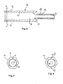
- FIG. 6 is an enlarged sectional view of the housing 14 of the first Coupling part 10 shown.
- an external thread 54 is formed, with which the first coupling part 10 in a version located at ground potential can be screwed into a contact carrier.
- FIG. 6 also shows a bore 57 in which the ground connection 40 of the Transmitting device 38 is soldered.
- Figure 8 shows a cross section through the housing 14 of the first coupling part 10 along the line A-A of Figure 6.
- the sleeve-like Section 16 of the housing 14 has a hexagonal outer cross section, to which a tool can be attached to the coupling part 10 with its Screw thread 54 into a socket.
- the sleeve-like section 16 the housing 14 has two receptacles 58 for the guide bolts 28, which already have been described in Figures 1 and 2.
- three receptacles 60 can also be provided, as shown in Figure 7. In that case, the opaque sleeve 22 three correspondingly arranged guide grooves 27.
- the first coupling part 10 and the second coupling part 12 are in coupled state shown.
- the end faces 26 and 26 'of the respective light-guiding element 18 pressed against each other, so that optical Signals that in the transparent core 24 of the light-guiding element 18 of the first coupling part 10 are fed through the end faces 26 and 26 ' in the transparent core 22 of the light-guiding element 18 of the second Coupling part 12 are transmitted.
- the opaque form Sleeves 22 of the light-guiding elements 18 are shielded from daylight Light tunnel.
- the coupling parts 10 and 12 of Figure 3 moved slightly towards each other without that the position of the light-guiding elements 18 relative to one another would have changed, so that the light transmission remains unaffected.
- the optical fiber coupling shown thus allows a certain tolerance in the relative arrangement of the two coupling parts 10 and 12 in the coupling direction, i.e. along the optical Axes of the light-guiding elements 18 through the central axis thereof is formed.
- the end faces 26 loaded with spring pressure also act and 26 'an offset of the optical axes of the light-guiding elements 18 opposite, i.e. they help align the two coupling parts with each other and maintain the aligned situation.
- the two coupling parts 10 and 12 are also coupled Condition shown. Unlike in Figures 3 and 4, here are the coupling parts 10 and 12, however, not arranged on a line, but tilted against each other. This means that the optical axes of the light-guiding elements 18, which each coincide with the axis of symmetry of the transparent core 24, stand at an angle to each other. Because of their spherical shape the end faces 26 and 26 'nevertheless lie against one another without gaps, so that the attenuation of the light as it passes through the end faces 26 and 26 ' keeps within limits. The optical fiber coupling can therefore be bent to a certain degree, without affecting their function. This is a huge advantage compared to the flat end faces usually used, which in such a Tilt would be lifted from each other, so that the light transmission would be strongly damped from one coupling part to the other.
- FIG. 5 shows the light guide coupling in its maximally bent position, in which the coupling parts are tilted against each other by 11 °. Another When tilted, daylight would enter the light tunnel and the optical one Falsify signal.
- the critical angle at which daylight enters the light tunnel would depend on the ratio of the wall thickness of the opaque Sleeves in the area of the end faces 26 and 26 'to the radius of curvature End faces 26, 26 '.
- the wall thickness is opaque sleeve 22 of the first coupling part in the region of the end face 26 less than that of the opaque sleeve 22 of the second coupling part 12, and thus decisive for the determination of the critical angle. It is approximately 1/5 of the radius of curvature of the spherical end faces 26 and 26 '.
- optical fiber coupling shown in Figures 1 to 5 includes a transmitter 38 and a receiver 40 that Features described so far, in particular the spherical design the end faces 26 and 26 'also for optical fiber couplings in the conventional Senses are intended in which no such active elements are provided are. In this case, light would go from an optical fiber into the light-guiding Element 18 of the first coupling part 10 fed through the end face 26 and the end face 26 'of the light-guiding element 18 of the second Coupling part 12 transmitted and in one with the light-guiding element 18th of the second coupling part connected optical fiber passed on.
- the Transmitting and receiving devices 38 and 40 are only advantageous Further development of the invention, which is described below.
- FIG. 9 shows a functional sketch of the transmission device 38.
- an input voltage V in present between the ground connection 42 and the signal connection 44 is scaled via a resistor 61 and is applied via a high pass consisting of a capacitor 62 and a resistor 64 to a light-emitting diode 66 which emits light corresponding to the applied voltage
- the relationship between the applied voltage V in and the radiation power S of the light-emitting diode 66 is shown schematically in a diagram in the right part of FIG. 9, the abscissa of which indicates the time and the ordinate of which indicates the input voltage V in and the radiation power S in undetermined units.
- FIG. 10 shows a functional sketch of the receiving device 40.
- the receiving device 40 contains a photodiode 68 which generates a voltage as a function of the intensity of the incident light. This is suitably amplified in a first circuit section with the aid of an operational amplifier 70, a resistor 72 and a capacitor 74 and inverted to an output voltage V out with the aid of a further operational amplifier 76.
- the relationship between the received radiation power S '(which corresponds to a damping factor corresponding to the radiation power emitted by the LED 66) and the output signal V out of the receiving device 40 is shown schematically in a diagram in the right part of FIG Ordinate shows the received radiation power S 'and the output voltage V out in indefinite units.
- the transmitting device 38 and the receiving device 40 are designed such that the output signal V out of the receiving device 40 corresponds to the input voltage V in despite possible attenuation of the transmitted optical signal. Thus, even if the optical signal transmitted between the coupling parts 10 and 12 is subjected to a certain attenuation, the effectively transmitted electrical signal V out is not attenuated compared to the original signal V in .
- the electrical input signal V in can be, for example, an electrical high-frequency signal that is conducted within two vehicle parts via a coaxial cable and is only converted into an optical signal with the aid of the transmitting device 38 to pass the optical fiber coupling.
- the further developed optical fiber coupling with the active elements 38 and 40 is also used when optical signals are already being transmitted in the vehicle parts by optical fibers. These are then first converted into an electrical signal in the first coupling part, which is then applied to the transmission device 38.
- the output signal V out of the receiving device 40 is then again converted into an optical signal in the second coupling part and fed into a further optical waveguide.
- FIG. 11 shows a section of a line coupling for use in combination with an automatic rail vehicle coupling in sectional view shown.
- An automatic clutch is used when the train parts must be coupled and uncoupled more frequently. Then the corresponding one Cable coupling designed so that its electrical and optical contacts also automatically coupled when the train parts are coupled become.
- the cable coupling includes two contact carriers 78 and 80, in which in addition a series of electrical contacts (not shown) also those described above Coupling parts 10 and 12 of the optical fiber coupling are used.
- the coupling parts 10 and 12 are on the end face with the thread 54 of the connecting bolt screwed into the contact carrier 78 or 80, whereby the thread 54 Is ground potential.
- the signal contact section 50 comes of the first coupling part 10 with a schematically illustrated first signal processing unit 82 and the signal connection section 50 of the second Coupling part 12 with a schematically illustrated second signal processing unit 84 electrically in contact.
- the first signal processing unit 82 via a coaxial cable 86 electrical signals and an optical fiber 88 optical signals supplied.
- the optical signals 88 are in a converter unit 90 converted into electrical signals and together with the electrical Signals from the electrical line 86 of a control unit 92 fed.
- the control unit 92 the two incoming electrical Signals processed into a multiplex signal that is sent to the signal connector 50 of the first coupling part is transmitted.
- the control unit 92 a microprocessor (not shown), which is a Industrial PC or a so-called Field Programmable Gate Array (FPGA) is.
- the control unit 92 also has a data input 94, via which you can access further data Signal processing information is supplied.
- the data line 94 signals that signals that have already been transmitted have arrived incomplete and have to be sent again.
- the conversion of the electrical multiplex signals into optical signals by the Transmitter 38 and its transmission from the first coupling part 10 the second coupling part 12 take place as described above. From the signal connection 50 of the second coupling part 12 arrive in the receiving device 40 generated electrical signals in a control unit 96 of the second signal processing unit 84. The Multiplex signals broken down into individual signals. The originally about the electrical Line 86 received signals are through an electrical line 98 forwarded. Those originally received via the optical fiber 88 Signals are converted into optical signals in a converter unit 100 and fed into an optical waveguide 102.
- Signals from the control unit can be transmitted via a further data line 104 96 are forwarded, for example error signals if signals are faulty were received.
- the control unit 96 also contains an industrial PC or an FPGA (not shown).
- the signal processing units 82 and 84 can also in the housing 14 of the Clutch boy parts can be accommodated. Furthermore, the signal processing units 82 and 84 each with a transmitting coupling part (similar to that first coupling part 10) and a receivable coupling part (similar the second coupling part 12). Then signals from both Sides of the clutch are transferred to the other side and the signal processing units 82 and 84 can be in both directions with each other communicate.
- the coupling parts 10 and 12 can, however, not only as shown in Fig. 11 in special contact carriers, but also directly in the coupling heads of one mechanical rail vehicle coupling, for example an automatic one Middle buffer coupling can be arranged (not shown).
- an automatic one Middle buffer coupling can be arranged (not shown).
Abstract
Description
Die vorliegende Erfindung betrifft eine Lichtleiterkupplung, insbesondere zum Übertragen von optischen Signalen zwischen miteinander gekuppelten Fahrzeugteilen, mit einem ersten und einem zweiten Kupplungsteil, die miteinander kuppelbar sind und in denen jeweils ein lichtleitendes Element gehalten ist, von denen mindestens eines derart elastisch vorgespannt ist, dass die lichtleitenden Elemente mit ihren Stirnflächen aneinander gedrückt werden, wenn die Kupplungsteile miteinander gekuppelt sind, um eine Lichtübertragung von einem lichtleitenden Element auf das andere zu gestatten.The present invention relates to an optical fiber coupling, in particular for Transmission of optical signals between mutually coupled vehicle parts, with a first and a second coupling part, which together can be coupled and in each of which a light-guiding element is held by which is at least one elastically biased so that the light-guiding Elements are pressed together with their end faces when the coupling parts are coupled together to transmit light from one allow light-guiding element to the other.
Eine derartige Lichtleiterkupplung ist beispielsweise aus DE 28 54 962 C2 bekannt, in der eine Mittelpufferkupplung für Schienenfahrzeuge beschrieben ist. Zu der Mittelpufferkupplung gehört eine Kabelkupplung, die unter anderem dazu dient, Impulse für die Steuerung des Brems- und Fahrstromes in einem Zugverband von einem Wagen auf den anderen zu übertragen. Die Kabelkupplung besteht aus zwei Kontaktträgern, von denen jeweils einer an jedem Wagen befestigt ist und in denen neben einer Vielzahl elektrischer Kontakte auch jeweils ein Lichtwellenleiter angeordnet ist. Von den Lichtwellenleitern ist einer derart elastisch vorgespannt, dass die beiden Lichtwellenleiter mit ihren Stirnflächen aneinander gedrückt werden, wenn die Kontaktträger beim Kuppeln der Wagen aufeinander zu bewegt werden. Über diese aneinandergedrückten Lichtwellenleiter können optische Signale von einem Wagen zum anderen übertragen werden.Such a light guide coupling is known for example from DE 28 54 962 C2, in which a central buffer coupling for rail vehicles is described. The middle buffer coupling includes a cable coupling, which among other things serves, impulses for the control of the braking and driving current in a train set transfer from one car to another. The cable coupling consists of two contact carriers, one of which is attached to each carriage is and in which in addition to a variety of electrical contacts an optical fiber is arranged. One of the optical fibers is such elastically biased that the two optical fibers with their end faces pressed together when the contact carriers when coupling the car to be moved towards each other. About these pressed optical fibers optical signals can be transmitted from one car to another.
Aus der DE 198 07 596 C2 ist eine Lichtwellenleitersteckverbindung der eingangs genannten Art bekannt, bei der nicht nur eines, sondern beide lichtleitende Elemente elastisch vorgespannt sind.From DE 198 07 596 C2 there is an optical fiber connector at the beginning known type, in which not only one, but both light-guiding Elements are elastically biased.
Wenn Lichtleiterkupplungen der eingangs genannten Art unter rauen Bedingungen verwendet werden, wie sie beispielsweise beim Übertragen von Signalen zwischen miteinander gekuppelten Fahrzeugteilen vorliegen, treten jedoch häufig Übertragungsfehler auf. Eine Ursache dafür liegt darin, dass die optischen Signale bei ihrer Übertragung von einem lichtleitenden Element auf das andere sowohl infolge eines Ver-satzes als auch infolge eines Verkippens der optischen Achsen der beiden lichtleitenden Elemente relativ zueinander stark gedämpft werden, was zu einer Verfälschung der optischen Signale führt. Eine derartige Verrückung und Verkippung der optischen Achsen der lichtleitenden Elemente lässt sich jedoch bei miteinander gekuppelten Fahrzeugteilen kaum vermeiden, da die beiden Kupplungsteile nicht starr miteinander verbunden sind und verhältnismässig stark mechanisch beansprucht werden. Weitere Ursachen für eine unzuverlässige Signalübertragung liegen in der Empfindlichkeit derartiger Lichtleiterkupplungen gegenüber Verschleiß und Verschmutzung, die im rauen Betrieb ebenfalls unvermeidlich sind. When fiber optic couplings of the type mentioned in harsh conditions can be used, such as when transmitting signals between vehicle parts that are coupled with each other, however, occur frequently Transmission error. One reason for this is that the optical Signals when they are transmitted from one light-conducting element to the other both due to a misalignment and due to a tilting of the optical The axes of the two light-conducting elements are strongly damped relative to one another become, which leads to a distortion of the optical signals. A such displacement and tilting of the optical axes of the light-guiding However, elements can hardly be found when vehicle parts are coupled together avoid since the two coupling parts are not rigidly connected to each other and are subject to relatively high mechanical loads. Other causes for an unreliable signal transmission lies in the sensitivity of such Fiber optic couplings against wear and pollution, which in harsh operation are also inevitable.
Um diese Probleme zu umgehen, wurde in DE 29 22 937 C2 eine Kabelkupplung vorgeschlagen, in der die lichtleitenden Elemente nicht mit ihren Stirnflächen aneinander stoßen, sondern das Licht mit Hilfe von Linsensteckern durch die Luft von einem lichtleitenden Element auf das andere übertragen wird. Eine derartige Leitungskupplung ist jedoch relativ kompliziert und teuer und konnte nicht die Zuverlässigkeit bieten, die man sich von ihr versprochen hatte.To avoid these problems, a cable coupling was described in DE 29 22 937 C2 proposed in which the light-guiding elements are not with their end faces butt the light through with the help of lens plugs the air is transferred from one light-conducting element to the other. A such line coupling is relatively complicated and expensive and could do not offer the reliability that was expected from her.
In Anbetracht der oben genannten Schwierigkeiten wurde in der DE 100 52 020
A1 vorgeschlagen, bei Anwendungen unter rauen Bedingungen auf eine herkömmliche
optische Kupplung von Lichtleitern vollständig zu verzichten und
stattdessen die in einem ersten Lichtwellenleiter geleiteten optischen Signale
zunächst in elektrische Signale umzuwandeln, diese über eine herkömmliche
Elektrokupplung zu übertragen, die übertragenen elektrischen Signale wiederum
in optische Signale umzuwandeln und in einen zweiten Lichtwellenleiter einzuspeisen.
Dabei verzichtet man allerdings auf die Vorteile einer
Lichtleiterkupplung, nämlich die einer höheren Übertragungsbandbreite und
einer geringeren Anfälligkeit gegenüber elektrischen Störfeldern, die
insbesondere immer dann auftreten, wenn in unmittelbarer Nachbarschaft auch
hohe Ströme übertragen werden, wie dies beispielsweise bei Kabelkupplungen
für Schienenfahrzeuge oft der Fall ist.In view of the difficulties mentioned above,
Der Erfindung liegt die Aufgabe zugrunde, eine Lichtleiterkupplung anzugeben, die die einfach im Aufbau ist und eine störungsunempfindliche Signalübertragung gestattet.The invention is based on the object of specifying an optical fiber coupling, which is simple in structure and interference-insensitive signal transmission allowed.
Diese Aufgabe wird bei einer Lichtleiterkupplung der eingangs genannten Art dadurch gelöst, dass die Stirnfläche des einen lichtleitenden Elementes sphärisch konkav und die Stirnfläche des anderen lichtleitenden Elementes mit gleichem Krümmungsradius sphärisch konvex ausgebildet ist. This task is carried out in an optical fiber coupling of the type mentioned solved in that the end face of a light-guiding element is spherical concave and the end face of the other light-guiding element with the same Radius of curvature is spherically convex.
Im gekuppelten Zustand liegt die konvexe Stirnfläche des einen Kupplungsteiles passgenau in der konkaven Stirnfläche des anderen Kupplungsteiles, und zwar ohne einen Luftspalt zwischen den Stirnflächen, der eine Dämpfung der optischen Signale zur Folge hätte.In the coupled state, the convex end face of one coupling part lies a perfect fit in the concave face of the other coupling part without an air gap between the end faces, which attenuates the optical Signals would result.
Unter der aus der Vorspannung des einen oder beider lichtleitender Elemente resultierenden Andruckkraft wird die konvexe Stirnfläche in die Aushöhlung der konkaven Stirnfläche gedrückt, wodurch die beiden Kupplungsteile automatisch miteinander zentriert werden. Dadurch wird bei der erfindungsgemäßen Lichtleiterkupplung ein Versatz der optischen Achsen der lichtleitenden Elemente vermieden, der wie oben beschrieben bei herkömmlichen Lichtleiterkupplungen ebenfalls zu einer Dämpfung der optischen Signale führt.Under that of the bias of one or both light-guiding elements resulting pressing force is the convex end face in the hollow of the concave face pressed, causing the two coupling parts to automatically centered with each other. This is in the optical fiber coupling according to the invention an offset of the optical axes of the light-guiding elements is avoided, that as described above with conventional optical fiber couplings also leads to an attenuation of the optical signals.
Darüber hinaus gestatten die sphärischen Stirnflächen eine Verkippung der optischen Achsen der lichtleitenden Elemente gegeneinander, ohne dass die Stirnflächen voneinander abgehoben werden. Bei einer derartigen Verkippung gleitet nämlich die sphärisch konvexe Stirnfläche an der sphärisch konkaven Stirnfläche entlang wie ein Gelenkkopf in einer Gelenkpfanne, ohne dass sich ein Luftspalt zwischen den Stirnflächen ergibt. Darin besteht ein großer Vorteil gegenüber herkömmlichen Lichtleiterkupplungen mit ebenen Stirnflächen, zwischen denen sich bei einer Verkippung der Kupplungsteile relativ zueinander unweigerlich ein Luftspalt bildet, der zu einer unzulässigen Dämpfung der übertragenen Signale führt.In addition, the spherical end faces allow the optical to be tilted Axes of the light guiding elements against each other without the End faces are lifted from each other. With such a tilt namely, the spherically convex face slides on the spherically concave Face along like a joint head in an acetabular cup without itself there is an air gap between the end faces. This is a big advantage compared to conventional optical fiber couplings with flat end faces, between which are relative to each other when the coupling parts are tilted inevitably forms an air gap that leads to an inadmissible damping of the transmitted Signals.
Die Möglichkeit einer geringen Dämpfung bei Verkippung der Kupplungsteile gegeneinander ist insbesondere von großer Bedeutung, wenn die Lichtleiterkupplung zum Übertragen von optischen Signalen zwischen miteinander gekuppelten Fahrzeugteilen, beispielsweise Schienenfahrzeugen, verwendet wird. Obwohl bei herkömmlichen Leitungskupplungen für Schienenfahrzeuge versucht wird, die Kupplungsteile von Signalkupplungen und Elektrokupplungen linear zu führen, d.h. ein Verkippen der Kupplungsteile gegeneinander zu verhindern, gelingt dies in der Praxis infolge der hohen mechanischen Belastungen nicht zuverlässig, was dann zu einer übermäßigen Dämpfung der übertragenen optischen Signale führt. Bei der erfindungsgemäßen Lichtleiterkupplung kann auf eine Linearführung im Prinzip völlig verzichtet werden, weil selbst relativ große Verkippungen der Kupplungsteile gegeneinander zu einer tolerierbaren Dämpfung des Signals führen. Die erfindungsgemäße Lichtleiterkupplung ist also zu einem gewissen Grade "knickbar".The possibility of low damping when the coupling parts are tilted against each other is particularly important when the optical fiber coupling for the transmission of optical signals between coupled ones Vehicle parts, for example rail vehicles, is used. Although tried with conventional cable couplings for rail vehicles the coupling parts of signal clutches and electric clutches linear, i.e. prevent tilting of the coupling parts against each other, This is achieved in practice due to the high mechanical loads not reliable, which then leads to excessive attenuation of the transmitted leads optical signals. In the optical fiber coupling according to the invention in principle, a linear guide can be completely dispensed with, because even relative large tilting of the coupling parts against each other to a tolerable Attenuation of the signal. The optical fiber coupling according to the invention is to a certain extent "kinkable".
Vorzugsweise bestehen die lichtleitenden Elemente jeweils aus einer lichtundurchlässigen Hülse und einem darin aufgenommenen transparenten Kern. Wenn die Kupplungsteile gekuppelt sind, bilden die lichtundurchlässigen Hülsen einen von Tageslicht abgeschirmten Lichttunnel.The light-conducting elements preferably each consist of an opaque one Sleeve and a transparent core accommodated therein. When the coupling parts are coupled, the opaque sleeves form a light tunnel shielded from daylight.
Die sphärische Stirnfläche des transparenten Kernes wird jeweils im Hülsenende stufenlos fortgesetzt. Damit auch beim Verkippen der lichtleitenden Elemente relativ zueinander kein Tageslicht in den transparenten Kern einfallen kann, darf die Wanddicke der Hülse im Bereich der Stirnflächen nicht zu gering sein. Vorteilhafterweise beträgt sie mindestens 1/10, vorzugsweise mindestens 1/5 des Krümmungsradius der Stirnfläche.The spherical end face of the transparent core is in each case in the sleeve end continuously continued. So even when the light-guiding elements are tilted no daylight can enter the transparent core relative to each other, the wall thickness of the sleeve in the area of the end faces must not be too small. It is advantageously at least 1/10, preferably at least 1/5 the radius of curvature of the face.
Die bisher beschriebene Lichtleiterkupplung kann auf herkömmliche Weise und mit den beschriebenen Vorteilen als passives Kopplungselement zwischen zwei Lichtwellenleitern verwendet werden. Beispielsweise kann ein optisches Signal über einen ersten Lichtwellenleiter über eine gewisse Strecke zum ersten Kupplungsteil geleitet werden und dort in dessen lichtleitendes Element eingespeist werden. Das optische Signal wird dann durch die Stirnflächen der beiden lichtleitenden Elemente auf das lichtleitende Element des zweiten Kupplungsteiles übertragen, von diesem in den zweiten Lichtwellenleiter eingespeist und darin über eine weitere Strecke geleitet.The optical fiber coupling described so far can in a conventional manner and with the described advantages as a passive coupling element between two Optical fibers are used. For example, an optical signal via a first optical fiber over a certain distance to the first coupling part are passed and fed there in its light-guiding element become. The optical signal is then through the end faces of the two light-guiding Elements on the light-guiding element of the second coupling part transmitted, fed from this into the second optical fiber and therein passed over a further distance.
Aufgrund ihres einfachen Aufbaus und ihren zuverlässigen Kupplungseigenschaften eignet sich die beschriebene Lichtleiterkupplung aber auch für einen breiteren und vielseitigeren Einsatz an. Eine große Vielseitigkeit wird erreicht, wenn die Lichtleiterkupplung mit aktiven Elementen zur Signalaufbereitung oder zum Erzeugen neuer Signale ausgestattet ist.Because of their simple structure and their reliable coupling properties the optical fiber coupling described is also suitable for one wider and more versatile use. Great versatility is achieved if the optical fiber coupling with active elements for signal processing or is equipped to generate new signals.
In einer bevorzugten Weiterbildung beinhaltet das erste Kupplungsteil daher eine Sendeeinrichtung, die aus elektrischen Signalen optische Signale erzeugt und diese in das lichtleitende Element des ersten Kupplungsteiles einspeist. Zusätzlich oder alternativ beinhaltet das zweite Kupplungsteil eine Empfangseinrichtung, die aus auf das lichtleitende Element des zweiten Kupplungsteiles übertragenen optischen Signalen elektrische Signale erzeugt.In a preferred development, the first coupling part therefore contains a transmitting device that generates optical signals from electrical signals and feeds it into the light-conducting element of the first coupling part. Additionally or alternatively, the second coupling part contains a receiving device, on the light-guiding element of the second coupling part transmitted optical signals generated electrical signals.
Darüber hinaus kann das erste Kupplungsteil einen Mikroprozessor beinhalten, der die elektrischen Signale für die Sendeeinrichtung bereitstellt. Auch das zweite Kupplungsteil kann einen Mikroprozessor beinhalten, der das in der Empfangsvorrichtung erzeugte elektrische Signal verarbeitet. Bei dieser Verarbeitung im Mikroprozessor des zweiten Kupplungsteils kann beispielsweise geprüft werden, ob die Signale vollständig übertragen wurden. Falls dies nicht der Fall sein sollte, kann der Mikroprozessor des ersten Kupplungsteiles beauftragt werden, diese Signale erneut zu senden. Der Mikroprozessor des ersten Kupplungsteiles kann beispielsweise der Sendeeinrichtung die Stärke des darin zu erzeugenden optischen Signales vorschreiben, die eine mögliche Dämpfung der optischen Signalübertragung infolge von Verschmutzung oder Betauung der Stirnflächen der lichtleitenden Elemente kompensiert. In addition, the first coupling part can contain a microprocessor, which provides the electrical signals for the transmitter. That too second coupling part can include a microprocessor, which in the Received device processed electrical signal processed. With this processing can be checked in the microprocessor of the second coupling part, for example whether the signals have been completely transmitted. If not Should this be the case, the microprocessor of the first coupling part can be commissioned to send these signals again. The microprocessor of the first coupling part can, for example, the strength of the transmission device in it generating optical signals prescribe a possible attenuation the optical signal transmission due to contamination or condensation of the End faces of the light-guiding elements compensated.
In einer vorteilhaften Weiterbildung ist der Mikroprozessor des ersten Kupplungsteiles programmiert, um mehrere individuelle Signale in elektrischen Multiplexsignalen zu vereinen, und der Mikroprozessor des zweiten Kupplungsteiles programmiert, um elektrische Multiplexsignale in individuelle Signale zu zerlegen. Dann können mehrere unterschiedliche Signale gleichzeitig über die Lichtleiterkupplung übertragen werden, wodurch Lichtleiterkupplungen eingespart werden können.In an advantageous development, the microprocessor of the first coupling part programmed to multiple individual signals in electrical multiplex signals to unite, and the microprocessor of the second coupling part programmed to split electrical multiplex signals into individual signals. Then several different signals can be sent simultaneously via the Optical fiber coupling are transmitted, whereby optical fiber couplings can be saved.
Vorzugsweise hat das erste und/oder das zweite Kupplungsteil ein Gehäuse, an dessen einem axialen Ende ein hülsenartiger Abschnitt ausgebildet ist, in dem das lichtieitende Element axial verschiebbar gelagert und in Richtung auf dieses eine axiale Ende elastisch vorgespannt ist, und an dessen anderem Ende ein Anschlussbolzen ausgebildet ist, der zum Einsetzen in einen Kontaktträger bestimmt ist. Der Anschlussbolzen besteht vorzugsweise aus zwei gegeneinander isolierten Abschnitten, von denen der eine mit einem Massepotential und der andere mit einer elektrischen Signalleitung verbunden ist, wenn der Anschlussbolzen in den Kontaktträger eingesetzt ist.The first and / or the second coupling part preferably has a housing one axial end of which a sleeve-like section is formed, in which the light-guiding element is mounted axially displaceable and in the direction of this one axial end is resiliently biased, and at the other end Connection bolt is formed, which is intended for insertion into a contact carrier is. The connecting bolt preferably consists of two against each other isolated sections, one of which has a ground potential and the another is connected to an electrical signal line when the connector bolt is inserted in the contact carrier.
Weitere Vorteile und Merkmale der Erfindung ergeben sich aus der folgenden Beschreibung, in der die Lichtleiterkupplung anhand eines Ausführungsbeispieles näher erläutert wird. Darin zeigen:
- Fig.1
- eine Schnittdarstellung eines ersten Kupplungsteiles einer Lichtleiterkupplung in Explosionsdarstellung (oben) und im zusammengesetzten Zustand (unten),
- Fig.2
- eine Schnittdarstellung eines zweiten Kupplungsteiles einer Lichtleiterkupplung in Explosionsdarstellung (oben) und im zusammengesetzten Zustand (unten),
- Fig.3
- eine Schnittdarstellung der Kupplungsteile von Figuren 1 und 2 im gekuppelten Zustand,
- Fig.4
- die gekuppelten Kupplungsteile von Figur 3, deren Abstand in Richtung der optischen Achse verkürzt ist,
- Fig.5
- die gekuppelten Kupplungsteile von Figur 3, deren optische Achsen gegeneinander verkippt sind,
- Fig.6
- einen Längsschnitt durch das Gehäuse des ersten Kupplungsteiles,
- Fig.7
- eine Querschnittsansicht des Gehäuses des ersten Kupplungsteiles,
- Fig.8
- eine Querschnittsansicht einer alternativen Ausführungsform des Gehäuses des ersten Kupplungsteiles,
- Fig.9
- eine Funktionsskizze einer Sendeeinrichtung des ersten Kupplungsteiles,
- Fig.10
- eine Funktionsskizze einer Empfangseinrichtung des zweiten Kupplungsteiles und
- Fig.11
- eine Schnittansicht eines Abschnitts einer Leitungskupplung für Schienenfahrzeuge mit zwei Kontaktträgern, in die jeweils ein Kupplungsteil der Lichtleiterkupplung eingesetzt ist.
- Fig.1
- 2 shows a sectional view of a first coupling part of an optical fiber coupling in an exploded view (top) and in the assembled state (bottom),
- Fig.2
- 2 shows a sectional view of a second coupling part of an optical fiber coupling in an exploded view (above) and in the assembled state (below),
- Figure 3
- 2 shows a sectional illustration of the coupling parts of FIGS. 1 and 2 in the coupled state,
- Figure 4
- the coupled coupling parts of Figure 3, the distance is shortened in the direction of the optical axis,
- Figure 5
- the coupled coupling parts of Figure 3, the optical axes are tilted against each other,
- Figure 6
- a longitudinal section through the housing of the first coupling part,
- Figure 7
- a cross-sectional view of the housing of the first coupling part,
- Figure 8
- 2 shows a cross-sectional view of an alternative embodiment of the housing of the first coupling part,
- Figure 9
- a functional sketch of a transmission device of the first coupling part,
- Figure 10
- a functional sketch of a receiving device of the second coupling part and
- Figure 11
- a sectional view of a portion of a line coupling for rail vehicles with two contact carriers, in each of which a coupling part of the optical fiber coupling is inserted.
In Figur 1 ist eine Längsschnittsansicht des ersten Kupplungsteiles 10 einer
Lichtleiterkupplung nach einer Weiterbildung der vorliegenden Erfindung in Explosionsdarstellung
(oben) und im zusammengesetzten Zustand (unten) gezeigt.
In Figur 2 ist eine Längsschnittsdarstellung des zweiten Kupplungsteiles 12 der
gleichen Lichtleiterkupplung in Explosionsdarstellung (oben) und im zusammengesetzten
Zustand (unten) gezeigt. Da das erste und das zweite Kupplungsteil
10 bzw. 12 in vielen Merkmalen identisch sind, werden sie im folgenden
gemeinsam beschrieben, wobei gleichartige Teile durch die gleichen Bezugszeichen
gekennzeichnet werden.In Figure 1 is a longitudinal sectional view of the
Die Kupplungsteile 10 und 12 haben jeweils ein Metallgehäuse 14 mit einem
hülsenartigen Abschnitt 16, in dem ein lichtleitendes Element 18 axial verschiebbar
gelagert ist. Die lichtleitenden Elemente 18 können gegen die Vorspannkraft
einer Feder 20 in den hülsenartigen Abschnitt 16 des jeweiligen Gehäuses
14 gedrückt werden. Anstatt mit der Feder 20 kann das lichtleitende
Element 18 auch durch im hülsenartigen Abschnitt eingeschlossenes Gas
pneumatisch vorgespannt werden. Die lichtleitenden Elemente 18 bestehen
jeweils aus einer lichtundurchlässigen Hülse 22 und einem darin aufgenommenen
transparenten Kern 24.The
Das lichtleitende Element 18 des ersten Kupplungsteils hat eine dem hülsenartigen
Gehäuseabschnitt 16 abgewandte sphärisch konkave Stirnfläche 26 (Figur
1) und das lichtleitende Element 18 des zweiten Kupplungsteiles 12 eine
sphärisch konvexe Stirnfläche 26' (Figur 2), deren Krümmungsradius mit demjenigen
der sphärisch konkaven Stirnfläche 26 übereinstimmt. Die sphärisch
konkave Stirnfläche 26 und die sphärisch konvexe Stirnfläche 26' sind nicht nur
im transparenten Kern 24 ausgebildet, sondern werden im axialen Ende der
jeweiligen Hülse 22 des lichtleitenden Elementes 18 stetig fortgesetzt. The light-guiding
In den Hülsen 22 sind Führungsnuten 27 ausgebildet, in die Führungsbolzen 28
eingreifen. Die Verschiebungsbewegung der lichtleitenden Elemente 18 wird
dadurch begrenzt, dass eines der Enden der Führungsnut 27 am Führungsbolzen
28 anstößt.
Der Innenraum des hülsenartigen Gehäuseabschnittes 16 besteht aus zwei zylindrischen
Abschnitten, einem innen liegenden Abschnitt 30 und einem weiter
außen liegenden Abschnitt 32, dessen Durchmesser größer ist als der des innen
liegenden Abschnittes 30. Zwischen den zylindrischen Innenraumabschnitten
30 und 32 ist ein Absatz 34 in der Gehäuseinnenwand ausgebildet. Im äußeren
Innenraumabschnitt 32 befinden sich das lichtleitende Element 18 und
die Feder 20, die sich mit einem Ende am lichtleitenden Element 18, mit dem
anderen Ende an einem Metallring 36 abstützt, der seinerseits am Absatz 34
aufliegt.The interior of the sleeve-
Im inneren Innenraumabschnitt 30 befindet sich beim ersten Kupplungsteil 10
eine Sendeeinrichtung 38 (Figur 1) und beim zweiten Kupplungsteil eine Empfangseinrichtung
40 (Figur 2). Sowohl die Sendeeinrichtung 38 als auch die
Empfangseinrichtung 40 haben einen Masseanschluss 42, der mit dem hülsenartigen
Abschnitt 16 des Gehäuses 14 verlötet ist, und einen Signalanschluss
44.The inner
Das Gehäuse 14 hat an seinem dem lichtleitenden Element 18 abgewandten
Ende einen hohlen Anschlussbolzen 46 mit einem Massenanschlussabschnitt
48, einem Signalanschlussabschnitt 50 und einem dazwischen liegenden Isolierungsstück
52, das die Abschnitte 48 und 50 voneinander elektrisch isoliert. Der
Signalanschluss 44 ist durch den Hohlraum im Anschlussbolzen 46 geführt und
mit dem Signalanschlussstück 50 verlötet. Der innere Innenraumabschnitt 30
und der Hohlraum des Anschlussbolzens 46 sind mit Vergussmasse ausgegossen,
die in den Figuren 1 und 2 durch Schraffierung dargestellt ist. The
In Figur 6 ist eine vergrößerte Schnittdarstellung des Gehäuses 14 des ersten
Kupplungsteiles 10 gezeigt. Wie in Figur 6 zu sehen, ist am Massenanschlussabschnitt
48 des Anschlussbolzens 46 ein Außengewinde 54 ausgebildet, mit
dem das erste Kupplungsteil 10 in eine auf Massepotential befindliche Fassung
in einem Kontaktträger einschraubbar ist. An der Innenseite des Masseanschlussabschnittes
48 befindet sich ein Innengewinde 56, in das das Isolierungsstück
52 einschraubbar ist (siehe Figur 1). In der Schnittdarstellung von
Figur 6 ist ferner eine Bohrung 57 gezeigt, in der der Massenanschluss 40 der
Sendeeinrichtung 38 verlötet wird.In Figure 6 is an enlarged sectional view of the
Figur 8 zeigt einen Querschnitt durch das Gehäuse 14 des ersten Kupplungsteiles
10 entlang der Linie A-A von Figur 6. Wie darin zu erkennen, hat der hülsenartige
Abschnitt 16 des Gehäuses 14 einen sechseckigen Außenquerschnitt,
an den ein Werkzeug ansetzbar ist, um das Kupplungsteil 10 mit seinem
Gewinde 54 in eine Fassung zu schrauben. Der hülsenartige Abschnitt 16
des Gehäuses 14 hat zwei Aufnahmen 58 für die Führungsbolzen 28, die bereits
in den Figuren 1 und 2 beschrieben wurden. Anstelle von zwei Aufnahmen
58 können auch drei um jeweils 120° versetzte Aufnahmen 60 vorgesehen sein,
wie dies in Figur 7 gezeigt ist. In dem Fall hat die lichtundurchlässige Hülse 22
drei entsprechend angeordnete Führungsnuten 27.Figure 8 shows a cross section through the
In Figur 3 sind das erste Kupplungsteil 10 und das zweite Kupplungsteil 12 im
gekuppelten Zustand gezeigt. Dabei werden die Stirnflächen 26 bzw. 26' des
jeweiligen lichtleitenden Elementes 18 aneinander gepresst, so dass optische
Signale, die in den transparenten Kern 24 des lichtleitenden Elementes 18 des
ersten Kupplungsteils 10 eingespeist werden, durch die Stirnflächen 26 und 26'
in den transparenten Kern 22 des lichtleitenden Elementes 18 des zweiten
Kupplungsteiles 12 übertragen werden. Dabei bilden die lichtundurchlässigen
Hülsen 22 der lichtleitenden Elemente 18 einen von Tageslicht abgeschirmten
Lichttunnel.In Figure 3, the
Da die beiden lichtleitenden Elemente 18 jeweils verschiebbar in dem Gehäuse
14 der Kupplungsteile 10 bzw. 12 gelagert sind, können die Kupplungsteile etwas
aufeinander zu und voneinander weg bewegt werden, ohne dass die Funktion
der Lichtleiterkupplung beinträchtigt würde. In Figur 4 sind beispielsweise
die Kupplungsteile 10 und 12 von Figur 3 etwas aufeinander zu bewegt, ohne
dass sich die Lage der lichtleitenden Elemente 18 zueinander geändert hätte,
so dass auch die Lichtübertragung unbeeinflusst bleibt. Die gezeigte Lichtleiterkupplung
gestattet also eine gewisse Toleranz in der relativen Anordnung der
beiden Kupplungsteile 10 und 12 in Kupplungsrichtung, d.h. entlang der optischen
Achsen der lichtleitenden Elemente 18, die durch die Mittelachse derselben
gebildet wird. Ferner wirken die mit Federdruck belasteten Stirnflächen 26
und 26' einem Versatz der optischen Achsen der lichtleitenden Elemente 18
entgegen, d.h. sie helfen, die beiden Kupplungsteile aneinander auszurichten
und die ausgerichtete Lage beizubehalten.Since the two light-guiding
In Figur 5 sind ebenfalls die beiden Kupplungsteile 10 und 12 im gekuppelten
Zustand gezeigt. Anders als in den Figuren 3 und 4 sind hier die Kupplungsteile
10 und 12 jedoch nicht auf einer Linie angeordnet, sondern gegeneinander verkippt.
Das bedeutet, dass die optischen Achsen der lichtleitenden Elemente 18,
die jeweils mit der Symmetrieachse des transparenten Kernes 24 zusammenfallen,
in einem Winkel zueinander stehen. Aufgrund ihrer sphärischen Ge-stalt
liegen die Stirnflächen 26 und 26' dennoch lückenlos aneinander an, so dass
sich die Dämpfung des Lichtes beim Durchtritt durch die Stirnflächen 26 und 26'
in Grenzen hält. Die Lichtleiterkupplung ist also zu einem gewissen Grad knickbar,
ohne dass ihre Funktion beeinträchtigt würde. Dies ist ein großer Vorteil
gegenüber üblicherweise verwendeten ebenen Stirnflächen, die bei einer derartigen
Verkippung voneinander abgehoben würden, so dass die Lichtübertragung
von einem Kupplungsteil auf das andere stark gedämpft würde.In Figure 5, the two
In Figur 5 ist die Lichtleiterkupplung in ihrer maximal geknickten Lage gezeigt,
in der die Kupplungsteile um 11° gegeneinander verkippt sind. Bei einer weiteren
Verkippung würde Tageslicht in den Lichttunnel eintreten und das optische
Signal verfälschen. Der Grenzwinkel, bei dem Tageslicht in den Lichttunnel eindringen
würde, hängt vom Verhältnis der Wanddicke der lichtundurchlässigen
Hülsen im Bereich der Stirnflächen 26 bzw. 26' zum Krümmungsradius der
Stirnflächen 26, 26' ab. Im gezeigten Ausführungsbeispiel ist die Wanddicke der
lichtundurchlässigen Hülse 22 des ersten Kupplungsteiles im Bereich der Stirnfläche
26 geringer als die der lichtundurchlässigen Hülse 22 des zweiten Kupplungsteiles
12, und somit für die Bestimmung des Grenzwinkels maßgeblich.
Sie beträgt etwa 1/5 des Krümmungsradius der sphärischen Stirnflächen 26
und 26'.FIG. 5 shows the light guide coupling in its maximally bent position,
in which the coupling parts are tilted against each other by 11 °. Another
When tilted, daylight would enter the light tunnel and the optical one
Falsify signal. The critical angle at which daylight enters the light tunnel
would depend on the ratio of the wall thickness of the opaque
Sleeves in the area of the end faces 26 and 26 'to the radius of curvature
End faces 26, 26 '. In the exemplary embodiment shown, the wall thickness is
Es wird betont, dass obwohl die in den Figuren 1 bis 5 gezeigte Lichtleiterkupplung
eine Sendeeinrichtung 38 und eine Empfangseinrichtung 40 beinhaltet, die
bisher beschriebenen Merkmale, insbesondere die sphärische Ausgestaltung
der Stirnflächen 26 und 26' auch für Lichtleiterkupplungen im herkömmlichen
Sinne gedacht sind, in denen keine derartigen aktiven Elemente vorgesehen
sind. In diesem Fall würde Licht von einem Lichtwellenleiter in das lichtleitende
Element 18 des ersten Kupplungsteiles 10 eingespeist, durch dessen Stirnfläche
26 und die Stirnfläche 26' des lichtleitenden Elementes 18 des zweiten
Kupplungsteils 12 übertragen und in einem mit dem lichtleitenden Element 18
des zweiten Kupplungsteils verbundenen Lichtwellenleiter weiter geleitet. Die
Sende- und Empfangseinrichtungen 38 bzw. 40 stellen lediglich eine vorteilhafte
Weiterbildung der Erfindung dar, die im folgenden beschrieben wird. It is emphasized that although the optical fiber coupling shown in Figures 1 to 5
includes a
In Figur 9 ist eine Funktionsskizze der Sendeeinrichtung 38 gezeigt. Wie dieser
zu entnehmen, wird eine zwischen dem Masseanschluss 42 und dem Signalanschluss
44 anliegende Eingangsspannung Vin über einen Widerstand 61 skaliert
und über einen aus einem Kondensator 62 und einem Widerstand 64 bestehenden
Hochpass an eine Leuchtdiode 66 angelegt, die der anliegenden
Spannung entsprechend Licht emittiert. Der Zusammenhang zwischen der anliegenden
Spannung Vin und der Strahlungsleistung S der Leuchtdiode 66 ist im
rechten Teil von Figur 9 in einem Diagramm schematisch dargestellt, dessen
Abszisse die Zeit anzeigt und dessen Ordinate die Eingangsspannung Vin und
die Strahlungsleistung S in nicht bestimmten Einheiten angibt.FIG. 9 shows a functional sketch of the
In Figur 10 ist eine Funktionsskizze der Empfangseinrichtung 40 gezeigt. Die
Empfangseinrichtung 40 beinhaltet eine Fotodiode 68, die in Abhängigkeit von
der Intensität einfallenden Lichts eine Spannung erzeugt. Diese wird in einem
ersten Schaltungsabschnitt mit Hilfe eines Operationsverstärkers 70, eines Widerstandes
72 und eines Kondensators 74 geeignet verstärkt und mit Hilfe eines
weiteren Operationsverstärkers 76 zu einer Ausgabespannung Vout invertiert.
Der Zusammenhang der empfangenen Strahlungsleistung S' (die multipliziert
mit einem Dämpfungsfaktor der von der LED 66 emittierten Strahlungsleistung
entspricht) und dem Ausgabesignal Vout der Empfangseinrichtung 40 ist im
rechten Teil von Figur 10 in einem Diagramm schematisch dargestellt, dessen
Abszisse wiederum die Zeit und dessen Ordinate die empfangene Strahlungsleistung
S' und die Ausgangsspannung Vout in unbestimmten Einheiten zeigt.FIG. 10 shows a functional sketch of the receiving
Die Sendeeinrichtung 38 und die Empfangseinrichtung 40 sind so ausgebildet,
dass das Ausgabesignal Vout der Empfangseinrichtung 40 trotz einer möglichen
Dämpfung des übertragenen optischen Signales der Eingangsspannung Vin
entspricht. Selbst wenn also das zwischen den Kupplungsteilen 10 und 12 übertragene
optische Signal einer gewissen Dämpfung unterworfen ist, ist das effektiv
übertragene elektrische Signal Vout gegenüber dem Ursprungssignal Vin nicht
gedämpft.The transmitting
Bei dem elektrischen Eingangssignal Vin kann es sich beispielsweise um ein
elektrisches Hochfrequenzsignal handeln, das innerhalb zweier Fahrzeugteile
über ein Koaxialkabel geleitet wird und nur zum Passieren der Lichtleiterkupplung
mit Hilfe der Sendeeinrichtung 38 in ein optisches Signal umgewandelt
wird. Die weitergebildete Lichtleiterkupplung mit den aktiven Elementen 38 und
40 findet aber auch Verwendung, wenn in den Fahrzeugteilen bereits optische
Signale durch Lichtwellenleiter übertragen werden. Diese werden dann im ersten
Kupplungsteil zunächst in ein elektrisches Signal umgewandelt, das dann
an die Sendeeinrichtung 38 angelegt wird. Das Ausgangssignal Vout der Empfangseinrichtung
40 wird dann im zweiten Kupplungsteil wiederum in ein optisches
Signal umgewandelt und in einen weiteren Lichtwellenleiter eingespeist.The electrical input signal V in can be, for example, an electrical high-frequency signal that is conducted within two vehicle parts via a coaxial cable and is only converted into an optical signal with the aid of the transmitting
In Figur 11 ist ein Abschnitt einer Leitungskupplung zur Verwendung in Kombination mit einer automatischen Schienenfahrzeugskupplung in Schnittdarstellung gezeigt. Eine automatische Kupplung wird verwendet, wenn die Zugteile häufiger gekuppelt und entkuppelt werden müssen. Dann ist die zugehörige Leitungskupplung so ausgebildet, dass ihre elektrischen und optischen Kontakte beim automatischen Kuppeln der Zugteile ebenfalls automatisch mitgekuppelt werden.FIG. 11 shows a section of a line coupling for use in combination with an automatic rail vehicle coupling in sectional view shown. An automatic clutch is used when the train parts must be coupled and uncoupled more frequently. Then the corresponding one Cable coupling designed so that its electrical and optical contacts also automatically coupled when the train parts are coupled become.
Die Leitungskupplung beinhaltet zwei Kontaktträger 78 und 80, in denen neben
einer Reihe elektrischer Kontakte (nicht gezeigt) auch die oben beschriebenen
Kupplungsteile 10 und 12 der Lichtleiterkupplung eingesetzt sind. Die Kupplungsteile
10 und 12 sind mit dem Gewinde 54 des Anschlussbolzens stirnseitig
in die Kontaktträger 78 bzw. 80 eingeschraubt, wodurch das Gewinde 54 auf
Massepotential gelegt wird. Gleichzeitig kommt der Signalkontaktabschnitt 50
des ersten Kupplungsteiles 10 mit einer schematisch dargestellten ersten Signalverarbeitungseinheit
82 und der Signalanschlussabschnitt 50 des zweiten
Kupplungsteiles 12 mit einer schematisch dargestellten zweiten Signalverarbeitungseinheit
84 elektrisch in Kontakt.The cable coupling includes two
Im gezeigten Ausführungsbeispiel werden der ersten Signalverarbeitungseinheit
82 über ein Koaxialkabel 86 elektrische Signale und über einen Lichtwellenleiter
88 optische Signale zugeführt. Die optischen Signale 88 werden in einer Wandlereinheit
90 in elektrische Signale umgewandelt und zusammen mit den elektrischen
Signalen aus der elektrischen Leitung 86 einer Steuerungseinheit 92
zugeführt. In der Steuerungseinheit 92 werden die beiden eingehenden elektrischen
Signale zu einem Multiplexsignal verarbeitet, das auf den Signalanschluss
50 des ersten Kupplungsteiles übertragen wird. Dazu hat die Steuerungseinheit
92 einen Mikroprozessor (nicht gezeigt), bei dem es sich um einen
Industrie-PC oder ein sogenanntes Field Programmable Gate Array (FPGA)
handelt.In the exemplary embodiment shown, the first
Die Steuerungseinheit 92 hat ferner einen Dateneingang 94, über den ihr weitere
Informationen zur Signalverarbeitung zugeführt werden. Beispielsweise kann
über die Datenleitung 94 signalisiert werden, dass bereits übertragene Signale
unvollständig angekommen sind und erneut zu senden sind.The
Die Umwandlung der elektrischen Multiplexsignale in optische Signale durch die
Sendeeinrichtung 38 und deren Übertragung vom ersten Kupplungsteil 10 auf
das zweite Kupplungsteil 12 erfolgen wie oben beschrieben. Vom Signalanschluss
50 des zweiten Kupplungsteiles 12 gelangen die in der Empfangseinrichtung
40 erzeugten elektrischen Signale in eine Steuerungseinheit 96 der
zweiten Signalverarbeitungseinheit 84. In der Steuerungseinheit 96 werden die
Multiplexsignale in individuelle Signale zerlegt. Die ursprünglich über die elektrische
Leitung 86 eingegangenen Signale werden über eine elektrische Leitung
98 weitergeleitet. Die ursprünglich über den Lichtwellenleiter 88 eingegangenen
Signale werden in einer Wandlereinheit 100 in optische Signale umgewandelt
und in einen Lichtwellenleiter 102 eingespeist.The conversion of the electrical multiplex signals into optical signals by the
Über eine weitere Datenleitung 104 können Signale von der Steuerungseinheit
96 weitergeleitet werden, beispielsweise Fehlersignale, wenn Signale fehlerhaft
empfangen wurden. Die Steuerungseinheit 96 enthält ebenfalls einen Industrie-PC
oder ein FPGA (nicht gezeigt).Signals from the control unit can be transmitted via a further data line 104
96 are forwarded, for example error signals if signals are faulty
were received. The
Die Signalverarbeitungseinheiten 82 und 84, können auch im Gehäuse 14 der
KuppJungsteile untergebracht werden. Ferner können die Signalverarbeitungseinheiten
82 und 84 jeweils mit einem sendefähigen Kupplungsteil (ähnlich dem
ersten Kupplungsteil 10) und einem empfangsfähigen Kupplungsteil (ähnlich
dem zweiten Kupplungsteil 12) verbunden sein. Dann können Signale von beiden
Seiten der Kupplung auf die jeweils andere Seite übertragen werden und
die Signalverarbeitungseinheiten 82 und 84 können in beide Richtungen miteinander
kommunizieren.The
Die Kupplungsteile 10 und 12 können allerdings nicht nur wie in Fig. 11 gezeigt
in speziellen Kontaktträgern, sondern auch direkt in den Kupplungsköpfen einer
mechanischen Schienenfahrzeugskupplung, beispielsweise einer automatischen
Mittelpufferkupplung angeordnet sein (nicht gezeigt). Die oben beschriebene
Unempfindlichkeit der optischen Signalkupplung gegenüber mechanischen
Toleranzen macht diese Anordnung möglich, die bei herkömmlichen optischen
Signalkupplungen nicht funktionieren würde. Dadurch kann in manchen
Fällen eine separate Leitungskupplung eingespart werden. The
- 1010
- erstes Kupplungsteilfirst coupling part
- 1212
- zweites Kupplungsteilsecond coupling part
- 1414
- Gehäusecasing
- 1616
- hülsenartiger Gehäuseabschnittsleeve-like housing section
- 1818
- lichtleitendes Elementlight-guiding element
- 2020
- Federfeather
- 2222
- lichtundurchlässige Hülseopaque sleeve
- 2424
- transparenter Kerntransparent core
- 26, 26'26, 26 '
- sphärische Stirnflächespherical face
- 2727
- Führungsnutguide
- 2828
- Führungsbolzenguide pins
- 3030
- innerer Innenraumabschnittinner interior section
- 3232
- äußerer Innenraumabschnittouter interior section
- 3434
- Absatzparagraph
- 3636
- Metallringmetal ring
- 3838
- Sendeeinheittransmission unit
- 4040
- Empfangseinheitreceiver unit
- 4242
- Masseanschlussground connection
- 4444
- Signalanschlusssignal connection
- 4646
- Anschlussbolzenconnecting bolt
- 4848
- Masseanschlussabschnitt .Earth connection section.
- 5050
- Signalanschlussabschnitt Signal connection section
- 5252
- Isolierungsstückinsulation piece
- 5454
- Außengewindeexternal thread
- 5656
- Innengewindeinner thread
- 5757
- Bohrungdrilling
- 5858
- FührungsbolzenaufnahmeGuide pin receptacle
- 6060
- FührungsbolzenaufnahmeGuide pin receptacle
- 6262
- Kondensatorcapacitor
- 6464
- Widerstandresistance
- 6666
- LEDLED
- 6868
- Photodiodephotodiode
- 7070
- Operationsverstärkeroperational amplifiers
- 7272
- Widerstandresistance
- 7474
- Kondensatorcapacitor
- 7676
- Operationsverstärkeroperational amplifiers
- 7878
- Kontaktträgercontact support
- 8080
- Kontaktträgercontact support
- 8282
- SignalverarbeitungseinheitSignal processing unit
- 8484
- SignalverarbeitungseinheitSignal processing unit
- 8686
- elektrische Signalleitungelectrical signal line
- 8888
- Lichtwellenleiteroptical fiber
- 9090
- Signalwandlersignal converter
- 9292
- Steuerungseinheitcontrol unit
- 9494
- Datenleitungdata line
- 9696
- Steuerungseinheitcontrol unit
- 9898
- elektrische Signalleitung electrical signal line
- 100100
- Signalwandlersignal converter
- 102102
- Lichtwellenleiteroptical fiber
- 104104
- Datenleitungdata line
Claims (12)
Applications Claiming Priority (2)
| Application Number | Priority Date | Filing Date | Title |
|---|---|---|---|
| DE10310148 | 2003-03-07 | ||
| DE10310148A DE10310148B4 (en) | 2003-03-07 | 2003-03-07 | Optical fiber coupling |
Publications (3)
| Publication Number | Publication Date |
|---|---|
| EP1455207A1 true EP1455207A1 (en) | 2004-09-08 |
| EP1455207A8 EP1455207A8 (en) | 2004-12-08 |
| EP1455207B1 EP1455207B1 (en) | 2005-11-23 |
Family
ID=32797884
Family Applications (1)
| Application Number | Title | Priority Date | Filing Date |
|---|---|---|---|
| EP03010282A Expired - Lifetime EP1455207B1 (en) | 2003-03-07 | 2003-05-07 | Connector for light conductor |
Country Status (9)
| Country | Link |
|---|---|
| US (1) | US6883973B2 (en) |
| EP (1) | EP1455207B1 (en) |
| JP (1) | JP4022515B2 (en) |
| CN (1) | CN1527079B (en) |
| AT (1) | ATE310968T1 (en) |
| AU (1) | AU2003255193B2 (en) |
| CA (1) | CA2447177C (en) |
| DE (2) | DE10310148B4 (en) |
| HK (1) | HK1068415A1 (en) |
Cited By (1)
| Publication number | Priority date | Publication date | Assignee | Title |
|---|---|---|---|---|
| WO2017182200A1 (en) * | 2016-04-19 | 2017-10-26 | Voith Patent Gmbh | Device for data and/or signal transmission |
Families Citing this family (15)
| Publication number | Priority date | Publication date | Assignee | Title |
|---|---|---|---|---|
| DE10310134B3 (en) * | 2003-03-07 | 2004-09-30 | Era-Contact Gmbh | Optical signal coupling |
| US7527437B2 (en) * | 2005-09-30 | 2009-05-05 | Rockwell Automation Technologies, Inc. | Sensor mounting structure with light pipe |
| US8348074B2 (en) * | 2007-02-15 | 2013-01-08 | Dellner Couplers Ab | Connector and connection block in a train coupler arranged for connection of a rail vehicles |
| CN202598170U (en) * | 2010-07-16 | 2012-12-12 | 东芝照明技术株式会社 | Lamp device and lighting device |
| CN103837955B (en) * | 2012-11-26 | 2016-08-31 | 福州高意通讯有限公司 | The assembling structure of a kind of optics and method |
| DE102015105514A1 (en) * | 2015-04-10 | 2016-10-13 | Voith Patent Gmbh | Device for transmitting data and / or signals |
| DE102015107230A1 (en) | 2015-05-08 | 2016-11-10 | Voith Patent Gmbh | Interface arrangement for a data, signal and / or voice transmission |
| CN106394595B (en) * | 2015-07-31 | 2018-03-30 | 瑞安市建鑫机械制造有限公司 | Compartment hinge connector and its processing technology |
| EP3379222B1 (en) | 2017-03-22 | 2020-12-30 | Methode Electronics Malta Ltd. | Magnetoelastic based sensor assembly |
| US11084342B2 (en) | 2018-02-27 | 2021-08-10 | Methode Electronics, Inc. | Towing systems and methods using magnetic field sensing |
| US11491832B2 (en) | 2018-02-27 | 2022-11-08 | Methode Electronics, Inc. | Towing systems and methods using magnetic field sensing |
| US11221262B2 (en) | 2018-02-27 | 2022-01-11 | Methode Electronics, Inc. | Towing systems and methods using magnetic field sensing |
| US11135882B2 (en) | 2018-02-27 | 2021-10-05 | Methode Electronics, Inc. | Towing systems and methods using magnetic field sensing |
| US10670479B2 (en) | 2018-02-27 | 2020-06-02 | Methode Electronics, Inc. | Towing systems and methods using magnetic field sensing |
| CN110426787B (en) * | 2019-07-04 | 2020-12-22 | 苏州安捷讯光电科技股份有限公司 | Non-contact optical fiber loop device with attenuation and manufacturing method thereof |
Citations (5)
| Publication number | Priority date | Publication date | Assignee | Title |
|---|---|---|---|---|
| GB381354A (en) * | 1931-10-26 | 1932-10-06 | Macintosh Cable Company Ltd | An improved electrical joint, coupling or connection |
| US4284311A (en) * | 1978-12-20 | 1981-08-18 | Scharfenbergkupplung Gmbh | Mechanical central buffer coupling for rail vehicles |
| US4964690A (en) * | 1988-06-09 | 1990-10-23 | Erni Elektroapparate Gmbh | Pin-and-socket connector for light wave conductors |
| DE19807596A1 (en) * | 1997-02-22 | 1998-09-10 | Spinner Gmbh Elektrotech | Optical fibre jack plug connector |
| US6481738B1 (en) * | 1998-06-15 | 2002-11-19 | Excalibur Vehicle Accessories (Proprietary) Limited | Connecting device |
Family Cites Families (8)
| Publication number | Priority date | Publication date | Assignee | Title |
|---|---|---|---|---|
| DE2922937C2 (en) | 1979-06-01 | 1981-07-02 | Fabeg Gmbh, 7518 Bretten | Cable coupling for the automatic coupling of electrical heating and / or control current lines as well as light guides for the optical transmission of commands, in particular for rail vehicles |
| US4699454A (en) * | 1984-03-29 | 1987-10-13 | American Telephone And Telegraph Company, At&T Bell Laboratories | Fiber optic connector |
| US4807955A (en) * | 1987-08-06 | 1989-02-28 | Amp Incorporated | Opto-electrical connecting means |
| SE465098B (en) * | 1989-04-25 | 1991-07-22 | Ericsson Telefon Ab L M | CONNECTOR |
| IT1239223B (en) * | 1990-02-20 | 1993-09-28 | Pirelli Cavi Spa | ADJUSTABLE OPTICAL CONNECTOR FOR CONNECTION OF OPTICAL FIBERS TO DISCRETE OPTICAL COMPONENTS AND SENSOR USING ONE OR MORE ADJUSTABLE CONNECTORS |
| CN1083242A (en) * | 1992-08-15 | 1994-03-02 | 华中理工大学 | Data acquiring system for traffic monitor |
| DE29701845U1 (en) * | 1997-02-04 | 1997-03-20 | Connex Elektrotechnische Steck | Interface with an opto-electrical converter |
| DE10052020A1 (en) | 2000-10-20 | 2002-05-08 | Knorr Bremse Systeme | connector |
-
2003
- 2003-03-07 DE DE10310148A patent/DE10310148B4/en not_active Expired - Fee Related
- 2003-05-07 EP EP03010282A patent/EP1455207B1/en not_active Expired - Lifetime
- 2003-05-07 DE DE50301732T patent/DE50301732D1/en not_active Expired - Lifetime
- 2003-05-07 AT AT03010282T patent/ATE310968T1/en not_active IP Right Cessation
- 2003-08-13 CN CN031278825A patent/CN1527079B/en not_active Expired - Fee Related
- 2003-10-20 AU AU2003255193A patent/AU2003255193B2/en not_active Ceased
- 2003-10-27 US US10/694,371 patent/US6883973B2/en not_active Expired - Lifetime
- 2003-10-28 CA CA002447177A patent/CA2447177C/en not_active Expired - Fee Related
- 2003-12-19 JP JP2003423376A patent/JP4022515B2/en not_active Expired - Fee Related
-
2005
- 2005-01-13 HK HK05100305.5A patent/HK1068415A1/en not_active IP Right Cessation
Patent Citations (5)
| Publication number | Priority date | Publication date | Assignee | Title |
|---|---|---|---|---|
| GB381354A (en) * | 1931-10-26 | 1932-10-06 | Macintosh Cable Company Ltd | An improved electrical joint, coupling or connection |
| US4284311A (en) * | 1978-12-20 | 1981-08-18 | Scharfenbergkupplung Gmbh | Mechanical central buffer coupling for rail vehicles |
| US4964690A (en) * | 1988-06-09 | 1990-10-23 | Erni Elektroapparate Gmbh | Pin-and-socket connector for light wave conductors |
| DE19807596A1 (en) * | 1997-02-22 | 1998-09-10 | Spinner Gmbh Elektrotech | Optical fibre jack plug connector |
| US6481738B1 (en) * | 1998-06-15 | 2002-11-19 | Excalibur Vehicle Accessories (Proprietary) Limited | Connecting device |
Cited By (2)
| Publication number | Priority date | Publication date | Assignee | Title |
|---|---|---|---|---|
| WO2017182200A1 (en) * | 2016-04-19 | 2017-10-26 | Voith Patent Gmbh | Device for data and/or signal transmission |
| US10752268B2 (en) | 2016-04-19 | 2020-08-25 | Voith Patent Gmbh | Device for data and/or signal transmission |
Also Published As
| Publication number | Publication date |
|---|---|
| HK1068415A1 (en) | 2005-04-29 |
| US6883973B2 (en) | 2005-04-26 |
| CA2447177A1 (en) | 2004-09-07 |
| US20040175076A1 (en) | 2004-09-09 |
| EP1455207B1 (en) | 2005-11-23 |
| EP1455207A8 (en) | 2004-12-08 |
| DE50301732D1 (en) | 2005-12-29 |
| JP4022515B2 (en) | 2007-12-19 |
| AU2003255193A1 (en) | 2004-09-23 |
| DE10310148B4 (en) | 2005-03-03 |
| CN1527079A (en) | 2004-09-08 |
| CN1527079B (en) | 2010-05-12 |
| JP2004268904A (en) | 2004-09-30 |
| AU2003255193B2 (en) | 2008-09-25 |
| ATE310968T1 (en) | 2005-12-15 |
| DE10310148A1 (en) | 2004-12-23 |
| CA2447177C (en) | 2007-08-07 |
Similar Documents
| Publication | Publication Date | Title |
|---|---|---|
| EP1455207B1 (en) | Connector for light conductor | |
| DE10310134B3 (en) | Optical signal coupling | |
| DE2812284C2 (en) | Alignment device for optical single fiber lines | |
| DE102008048440B4 (en) | Central buffer coupling for rail vehicles | |
| EP0395708B1 (en) | Coupling part | |
| EP0313738B1 (en) | Method for bidirectionnally transmitting optical signals over optical fibres | |
| EP1813967A2 (en) | Light curtain | |
| EP3280629A1 (en) | Device for transmitting data and/or signals | |
| DE2741585B2 (en) | Plug-in connector for fiber optic cables | |
| EP1187262A2 (en) | Insulating body for a plug connector for optical or electrical signal transmission | |
| EP0304639A2 (en) | Plug and socket device for the transmission of electrical energy and optical signals | |
| DE4414862C2 (en) | Optical fiber connector with monitoring device | |
| EP1869805B1 (en) | Electrooptical coupling device | |
| EP0874482A2 (en) | Arrangement for transmitting and receiving optical signals | |
| DE10002328B4 (en) | Optical transmitting and receiving unit with a mounting platform having two light apertures | |
| WO2015117251A1 (en) | Optical plug that can be assembled at the location of use | |
| WO2000016142A2 (en) | Multi-channel optical coupling device | |
| DE19714970C2 (en) | Coupling element for fiber optic cables | |
| DE10009964A1 (en) | Connection device for optical conductor, has fluorescent component coupled to conductor so light emitted by conductor is absorbed and fluorescent light is generated in fluorescent component | |
| DE3733018B4 (en) | optocoupler | |
| DE2220115C3 (en) | Plug-in coupling | |
| DE4141009A1 (en) | Optical waveguide connector having terminating member | |
| DE19749910A1 (en) | Coupling device for connecting optical fiber to electronic module | |
| DE202005005767U1 (en) | Electro-optical coupling for data transmission systems has set of field bus connections with optical link and valve stations mounted on support rails | |
| DE10131374A1 (en) | Arrangement for positioning an optical fiber |
Legal Events
| Date | Code | Title | Description |
|---|---|---|---|
| PUAI | Public reference made under article 153(3) epc to a published international application that has entered the european phase |
Free format text: ORIGINAL CODE: 0009012 |
|
| AK | Designated contracting states |
Kind code of ref document: A1 Designated state(s): AT BE BG CH CY CZ DE DK EE ES FI FR GB GR HU IE IT LI LU MC NL PT RO SE SI SK TR |
|
| AX | Request for extension of the european patent |
Extension state: AL LT LV MK |
|
| 17P | Request for examination filed |
Effective date: 20041203 |
|
| GRAP | Despatch of communication of intention to grant a patent |
Free format text: ORIGINAL CODE: EPIDOSNIGR1 |
|
| AKX | Designation fees paid |
Designated state(s): AT BE BG CH CY CZ DE DK EE ES FI FR GB GR HU IE IT LI LU MC NL PT RO SE SI SK TR |
|
| GRAS | Grant fee paid |
Free format text: ORIGINAL CODE: EPIDOSNIGR3 |
|
| GRAA | (expected) grant |
Free format text: ORIGINAL CODE: 0009210 |
|
| AK | Designated contracting states |
Kind code of ref document: B1 Designated state(s): AT BE BG CH CY CZ DE DK EE ES FI FR GB GR HU IE IT LI LU MC NL PT RO SE SI SK TR |
|
| PG25 | Lapsed in a contracting state [announced via postgrant information from national office to epo] |
Ref country code: IT Free format text: LAPSE BECAUSE OF FAILURE TO SUBMIT A TRANSLATION OF THE DESCRIPTION OR TO PAY THE FEE WITHIN THE PRESCRIBED TIME-LIMIT;WARNING: LAPSES OF ITALIAN PATENTS WITH EFFECTIVE DATE BEFORE 2007 MAY HAVE OCCURRED AT ANY TIME BEFORE 2007. THE CORRECT EFFECTIVE DATE MAY BE DIFFERENT FROM THE ONE RECORDED. Effective date: 20051123 Ref country code: IE Free format text: LAPSE BECAUSE OF FAILURE TO SUBMIT A TRANSLATION OF THE DESCRIPTION OR TO PAY THE FEE WITHIN THE PRESCRIBED TIME-LIMIT Effective date: 20051123 Ref country code: CZ Free format text: LAPSE BECAUSE OF FAILURE TO SUBMIT A TRANSLATION OF THE DESCRIPTION OR TO PAY THE FEE WITHIN THE PRESCRIBED TIME-LIMIT Effective date: 20051123 Ref country code: SI Free format text: LAPSE BECAUSE OF FAILURE TO SUBMIT A TRANSLATION OF THE DESCRIPTION OR TO PAY THE FEE WITHIN THE PRESCRIBED TIME-LIMIT Effective date: 20051123 Ref country code: FI Free format text: LAPSE BECAUSE OF FAILURE TO SUBMIT A TRANSLATION OF THE DESCRIPTION OR TO PAY THE FEE WITHIN THE PRESCRIBED TIME-LIMIT Effective date: 20051123 Ref country code: SK Free format text: LAPSE BECAUSE OF FAILURE TO SUBMIT A TRANSLATION OF THE DESCRIPTION OR TO PAY THE FEE WITHIN THE PRESCRIBED TIME-LIMIT Effective date: 20051123 Ref country code: NL Free format text: LAPSE BECAUSE OF FAILURE TO SUBMIT A TRANSLATION OF THE DESCRIPTION OR TO PAY THE FEE WITHIN THE PRESCRIBED TIME-LIMIT Effective date: 20051123 Ref country code: RO Free format text: LAPSE BECAUSE OF FAILURE TO SUBMIT A TRANSLATION OF THE DESCRIPTION OR TO PAY THE FEE WITHIN THE PRESCRIBED TIME-LIMIT Effective date: 20051123 |
|
| REG | Reference to a national code |
Ref country code: GB Ref legal event code: FG4D Free format text: NOT ENGLISH |
|
| REG | Reference to a national code |
Ref country code: CH Ref legal event code: EP |
|
| REF | Corresponds to: |
Ref document number: 50301732 Country of ref document: DE Date of ref document: 20051229 Kind code of ref document: P |
|
| REG | Reference to a national code |
Ref country code: IE Ref legal event code: FG4D Free format text: LANGUAGE OF EP DOCUMENT: GERMAN |
|
| GBT | Gb: translation of ep patent filed (gb section 77(6)(a)/1977) |
Effective date: 20060107 |
|
| REG | Reference to a national code |
Ref country code: SE Ref legal event code: TRGR |
|
| PG25 | Lapsed in a contracting state [announced via postgrant information from national office to epo] |
Ref country code: BG Free format text: LAPSE BECAUSE OF FAILURE TO SUBMIT A TRANSLATION OF THE DESCRIPTION OR TO PAY THE FEE WITHIN THE PRESCRIBED TIME-LIMIT Effective date: 20060223 Ref country code: GR Free format text: LAPSE BECAUSE OF FAILURE TO SUBMIT A TRANSLATION OF THE DESCRIPTION OR TO PAY THE FEE WITHIN THE PRESCRIBED TIME-LIMIT Effective date: 20060223 Ref country code: DK Free format text: LAPSE BECAUSE OF FAILURE TO SUBMIT A TRANSLATION OF THE DESCRIPTION OR TO PAY THE FEE WITHIN THE PRESCRIBED TIME-LIMIT Effective date: 20060223 |
|
| PG25 | Lapsed in a contracting state [announced via postgrant information from national office to epo] |
Ref country code: ES Free format text: LAPSE BECAUSE OF FAILURE TO SUBMIT A TRANSLATION OF THE DESCRIPTION OR TO PAY THE FEE WITHIN THE PRESCRIBED TIME-LIMIT Effective date: 20060306 |
|
| PG25 | Lapsed in a contracting state [announced via postgrant information from national office to epo] |
Ref country code: PT Free format text: LAPSE BECAUSE OF FAILURE TO SUBMIT A TRANSLATION OF THE DESCRIPTION OR TO PAY THE FEE WITHIN THE PRESCRIBED TIME-LIMIT Effective date: 20060424 |
|
| NLV1 | Nl: lapsed or annulled due to failure to fulfill the requirements of art. 29p and 29m of the patents act | ||
| PG25 | Lapsed in a contracting state [announced via postgrant information from national office to epo] |
Ref country code: AT Free format text: LAPSE BECAUSE OF NON-PAYMENT OF DUE FEES Effective date: 20060507 |
|
| PG25 | Lapsed in a contracting state [announced via postgrant information from national office to epo] |
Ref country code: HU Free format text: LAPSE BECAUSE OF FAILURE TO SUBMIT A TRANSLATION OF THE DESCRIPTION OR TO PAY THE FEE WITHIN THE PRESCRIBED TIME-LIMIT Effective date: 20060524 |
|
| PG25 | Lapsed in a contracting state [announced via postgrant information from national office to epo] |
Ref country code: MC Free format text: LAPSE BECAUSE OF NON-PAYMENT OF DUE FEES Effective date: 20060531 Ref country code: BE Free format text: LAPSE BECAUSE OF NON-PAYMENT OF DUE FEES Effective date: 20060531 |
|
| REG | Reference to a national code |
Ref country code: IE Ref legal event code: FD4D |
|
| ET | Fr: translation filed | ||
| PLBE | No opposition filed within time limit |
Free format text: ORIGINAL CODE: 0009261 |
|
| STAA | Information on the status of an ep patent application or granted ep patent |
Free format text: STATUS: NO OPPOSITION FILED WITHIN TIME LIMIT |
|
| 26N | No opposition filed |
Effective date: 20060824 |
|
| BERE | Be: lapsed |
Owner name: ERA-CONTACT G.M.B.H. Effective date: 20060531 |
|
| REG | Reference to a national code |
Ref country code: CH Ref legal event code: PL |
|
| PG25 | Lapsed in a contracting state [announced via postgrant information from national office to epo] |
Ref country code: LI Free format text: LAPSE BECAUSE OF NON-PAYMENT OF DUE FEES Effective date: 20070531 Ref country code: CH Free format text: LAPSE BECAUSE OF NON-PAYMENT OF DUE FEES Effective date: 20070531 |
|
| PG25 | Lapsed in a contracting state [announced via postgrant information from national office to epo] |
Ref country code: EE Free format text: LAPSE BECAUSE OF FAILURE TO SUBMIT A TRANSLATION OF THE DESCRIPTION OR TO PAY THE FEE WITHIN THE PRESCRIBED TIME-LIMIT Effective date: 20051123 |
|
| PG25 | Lapsed in a contracting state [announced via postgrant information from national office to epo] |
Ref country code: TR Free format text: LAPSE BECAUSE OF FAILURE TO SUBMIT A TRANSLATION OF THE DESCRIPTION OR TO PAY THE FEE WITHIN THE PRESCRIBED TIME-LIMIT Effective date: 20051123 Ref country code: LU Free format text: LAPSE BECAUSE OF NON-PAYMENT OF DUE FEES Effective date: 20060507 |
|
| PG25 | Lapsed in a contracting state [announced via postgrant information from national office to epo] |
Ref country code: CY Free format text: LAPSE BECAUSE OF FAILURE TO SUBMIT A TRANSLATION OF THE DESCRIPTION OR TO PAY THE FEE WITHIN THE PRESCRIBED TIME-LIMIT Effective date: 20051123 |
|
| PGFP | Annual fee paid to national office [announced via postgrant information from national office to epo] |
Ref country code: GB Payment date: 20130522 Year of fee payment: 11 Ref country code: DE Payment date: 20130624 Year of fee payment: 11 Ref country code: SE Payment date: 20130521 Year of fee payment: 11 |
|
| PGFP | Annual fee paid to national office [announced via postgrant information from national office to epo] |
Ref country code: FR Payment date: 20130604 Year of fee payment: 11 |
|
| REG | Reference to a national code |
Ref country code: DE Ref legal event code: R119 Ref document number: 50301732 Country of ref document: DE |
|
| GBPC | Gb: european patent ceased through non-payment of renewal fee |
Effective date: 20140507 |
|
| PG25 | Lapsed in a contracting state [announced via postgrant information from national office to epo] |
Ref country code: SE Free format text: LAPSE BECAUSE OF NON-PAYMENT OF DUE FEES Effective date: 20140508 |
|
| REG | Reference to a national code |
Ref country code: SE Ref legal event code: EUG |
|
| REG | Reference to a national code |
Ref country code: DE Ref legal event code: R119 Ref document number: 50301732 Country of ref document: DE Effective date: 20141202 |
|
| REG | Reference to a national code |
Ref country code: FR Ref legal event code: ST Effective date: 20150130 |
|
| PG25 | Lapsed in a contracting state [announced via postgrant information from national office to epo] |
Ref country code: DE Free format text: LAPSE BECAUSE OF NON-PAYMENT OF DUE FEES Effective date: 20141202 |
|
| PG25 | Lapsed in a contracting state [announced via postgrant information from national office to epo] |
Ref country code: GB Free format text: LAPSE BECAUSE OF NON-PAYMENT OF DUE FEES Effective date: 20140507 Ref country code: FR Free format text: LAPSE BECAUSE OF NON-PAYMENT OF DUE FEES Effective date: 20140602 |