EP1453355B1 - Signal processing in a hearing aid - Google Patents
Signal processing in a hearing aid Download PDFInfo
- Publication number
- EP1453355B1 EP1453355B1 EP03405125A EP03405125A EP1453355B1 EP 1453355 B1 EP1453355 B1 EP 1453355B1 EP 03405125 A EP03405125 A EP 03405125A EP 03405125 A EP03405125 A EP 03405125A EP 1453355 B1 EP1453355 B1 EP 1453355B1
- Authority
- EP
- European Patent Office
- Prior art keywords
- coefficients
- signal
- frequency
- input signal
- noise suppression
- Prior art date
- Legal status (The legal status is an assumption and is not a legal conclusion. Google has not performed a legal analysis and makes no representation as to the accuracy of the status listed.)
- Expired - Lifetime
Links
Images

Classifications
-
- H—ELECTRICITY
- H04—ELECTRIC COMMUNICATION TECHNIQUE
- H04R—LOUDSPEAKERS, MICROPHONES, GRAMOPHONE PICK-UPS OR LIKE ACOUSTIC ELECTROMECHANICAL TRANSDUCERS; DEAF-AID SETS; PUBLIC ADDRESS SYSTEMS
- H04R25/00—Deaf-aid sets, i.e. electro-acoustic or electro-mechanical hearing aids; Electric tinnitus maskers providing an auditory perception
- H04R25/50—Customised settings for obtaining desired overall acoustical characteristics
- H04R25/505—Customised settings for obtaining desired overall acoustical characteristics using digital signal processing
-
- H—ELECTRICITY
- H04—ELECTRIC COMMUNICATION TECHNIQUE
- H04R—LOUDSPEAKERS, MICROPHONES, GRAMOPHONE PICK-UPS OR LIKE ACOUSTIC ELECTROMECHANICAL TRANSDUCERS; DEAF-AID SETS; PUBLIC ADDRESS SYSTEMS
- H04R2225/00—Details of deaf aids covered by H04R25/00, not provided for in any of its subgroups
- H04R2225/43—Signal processing in hearing aids to enhance the speech intelligibility
-
- H—ELECTRICITY
- H04—ELECTRIC COMMUNICATION TECHNIQUE
- H04R—LOUDSPEAKERS, MICROPHONES, GRAMOPHONE PICK-UPS OR LIKE ACOUSTIC ELECTROMECHANICAL TRANSDUCERS; DEAF-AID SETS; PUBLIC ADDRESS SYSTEMS
- H04R25/00—Deaf-aid sets, i.e. electro-acoustic or electro-mechanical hearing aids; Electric tinnitus maskers providing an auditory perception
- H04R25/35—Deaf-aid sets, i.e. electro-acoustic or electro-mechanical hearing aids; Electric tinnitus maskers providing an auditory perception using translation techniques
- H04R25/356—Amplitude, e.g. amplitude shift or compression
Definitions
- the invention relates to a device and a method for signal processing in a hearing aid according to the preambles of the independent claims.
- the invention is particularly suitable for improving speech intelligibility by suppressing noise in hearing aids or hearing aids.
- a generic method is for example from the EP 1 067 821 A1 known.
- a hearing aid is described in which there is a suppression of noise in an input signal in a main signal path, which has neither a transformation in the frequency domain nor a division into subband signals, but only a suppression filter.
- a transfer function of the suppression filter is periodically re-determined due to attenuation factors which are determined in a signal analysis path parallel to the main signal path. The attenuation factors are used to attenuate signal components in frequency bands with a significant amount of noise.
- the suppression filter is implemented as a transversal filter, whose impulse response is periodically expressed as the weighted sum of the impulse responses of transversal filters Bandpass filters is recalculated. In this way, a processing with a low signal delay is possible.
- the term "adaptation of a signal” means both amplification and attenuation.
- the invention makes it possible, the amplitude response of the filter to changing voice and interference signals and to the needs of a to match a person with the same name, whereby a delay time for the filtering of the input signal is kept small.
- Another advantage is that the compression gain allows different gain values for different frequency ranges of the input signal.
- Another advantage is that only a single controllable filter is used both for compression enhancement and for noise suppression.
- a signal level is determined from a sub-signal of the input signal, which is formed by filtering the input signal and dividing into sub-signals with signal components in only one frequency range at a time.
- the signal levels are determined iteratively as instantaneous rms values of a signal power in the respective frequency ranges of the input signal. This makes it possible to track the compression gain with a temporal resolution corresponding to a sampling rate of the input signal.
- the modulation depths d m are determined from a temporal sequence of maximum and minimum values of a signal level p m in the respective frequency range ⁇ m . This makes it possible to selectively filter out weakly modulated, ie monotone, noise.
- Time constants for the adaptation of the Noise suppression is preferably in the range of around 50 milliseconds or less.
- the frequency ranges ⁇ m for the noise suppression are small in comparison with the frequency ranges F n for the compression gain.
- at least one frequency range F n comprises two or more frequency ranges ⁇ m .
- filters for determining proportions of the input signal in the frequency ranges ⁇ m have a greater signal propagation time or delay than filters for the frequency ranges F n . This allows a sharp division of the frequency range to suppress interference and at the same time a rapid adjustment of the compression gain to a changing voice signal.
- a maximum tolerable delay for the adaptation of coefficients of the compression gain is 5 milliseconds, values below 2.5 milliseconds are preferred. Values below one millisecond can be achieved according to the invention.
- the filter is not tracked exactly to the newly calculated coefficients in each sampling interval. Instead, it is tracked only according to one or more changed coefficients. This allows adaptation with low computational effort and correspondingly low energy consumption.
- the adaptation preferably takes place only for the one or more coefficients whose change exceeds a predetermined threshold or which is comparatively large or largest. Also possible is a periodic change of one or a few coefficients or a pseudorandom traversal and adaptation of all coefficients.
- an influence of the noise suppression is taken into account in the determination of the coefficients for the compression gain.
- a means to Determining Noise Suppression Coefficients A compression gain coefficient determining means Corresponding to a signal attenuation caused by the noise suppression.
- a hearing aid according to the invention has means for carrying out the method according to the invention.
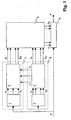
- FIG. 1 schematically shows a structure of the signal processing in a hearing aid according to the invention.
- An input signal X is fed to a controllable filter 6, to a means for determining a compression gain 7 and to a means for determining a noise suppression 8.
- the controllable filter 6 is designed to form an output signal Y in accordance with filter coefficients c 1 ... C M.
- the input signal X is fed to a first filter unit 1.
- the signal components x 1 .x N are used to calculate parameters or coefficients or adaptation values of the compression gain g 1 ..g M. These coefficients are also referred to as gain values with regard to the amplification function of the hearing aid. However, other coefficients are also referred to as gain values.
- the input signal X is fed to a second filter unit 2.
- the signal components y 1 .y M are used to calculate parameters or coefficients or adaptation values of the noise suppression a 1 .a M. These coefficients are also referred to as attenuation values in view of the noise suppression achieved thereby.
- the combining unit 5 combines the coefficients of the compression gain g 1 ..g M with the coefficients of noise suppression a 1 ..a M and calculates therefrom combined logarithmic amplification values c 1 ... c M as filter coefficients of the controllable filter 6.
- the noise suppression signal processing 4 transmits correction values r 1 ..r N corresponding to a respective signal attenuation caused by the noise suppression in the frequency ranges F 1 ..F n .
- the first filter unit 1 and the second filter unit 2 are not implemented as separate units, but as a combined filter unit. For example, filtering with broad frequency bands is carried out sequentially to determine the signal components x 1 ..x N , and these filtered signals are further filtered to determine the signal components y 1 ..y M.
- the invention in the embodiment shown works in summary as follows:
- the input signal is split into three signal paths, a main signal path with a controllable filter, a first parallel signal analysis path for the compression gain, and a second parallel signal analysis path for noise suppression.
- FIG. 12 shows a block diagram of a calculation of gain values in compression amplification signal processing 3.
- signal levels in N are computed in relatively few frequency ranges.
- FIG. 2 shows the calculation for one of these N frequency ranges, for the remaining frequency ranges the same structure is used.
- a signal component x n in this frequency range a signal power is formed in a block 21, for example, as a running sum of squared signal values.
- a signal level p n is formed by logarithmization.
- the term signal level here refers to the effective value of the instantaneous signal power in the frequency range F n expressed in a logarithmic number range, eg in dB.
- a modified signal level p n ' is calculated by subtracting 23 a correction value r n .
- correction values r n will be discussed separately below.
- Each frequency range F n of the compression gain is assigned at least one frequency range ⁇ m of the noise suppression.
- ⁇ m in the FIG. 2 if these are three, corresponding to blocks 24, 24 ', 24 "
- These functions f m into account an individual hearing loss and audiological experience.
- Parameters, amplification values or hearing correction values contained in the functions f m are preferably user-specific and stored, for example, in an EPROM of the hearing device.
- the total number of these functions f m and the gain values g m , ie over all N frequency ranges F n of the compression gain, is equal to the number M of the frequency ranges ⁇ m of the noise suppression.
- the signal levels p n must be determined such that Differences between quiet and loud consecutive phonemes are well captured.
- the continuously determined amplification values g m must be applied in a timely manner to those signal sections in which the associated phonemes are located, ie the amplification values must act synchronously on the audio signal X. So fast, in the rhythm of successive phonemes acting, synchronous compression gain gives only good results when the number of separate frequency ranges is chosen small, for example, N ⁇ 5, preferably N ⁇ 3.
- the signal analysis for determining signal levels in frequency ranges f n for the compression gain is preferably carried out iteratively, wherein current signal levels are determined for each new value of the input signal.
- recursive signal analysis methods are preferably used.
- the noise suppression is about attenuating sub-signals in frequency ranges of the audio signal, which are mainly only monotone noise.
- the signal level p m is formed in segments for segments of a length of about 20-30 ms as the instantaneous effective value of the signal power in the corresponding frequency range ⁇ m .
- the noise suppression can be tracked with a temporal resolution p m, for example under 50 ms.
- a stored maximum value is either reduced by a small increment linearly or according to an exponential function in each sampling interval, or the current level value is accepted if it exceeds this reduced maximum value.
- the minimum value is increased by a small increment in each sampling interval, or the current level value is adopted if it falls below the raised minimum value.
- the modulation depth is the difference between these two estimates. A small modulation depth thus arises at constant signal energy. In order to avoid sudden changes in the modulation depth, the difference values thus determined are preferably subjected to a smoothing process. By appropriate selection of the mentioned increments, the extremes with time constants in the range of a few seconds sound.
- the modulation depth assumes values of 30 dB and more.
- the low frequency range up to about 500 Hz is often dominated by monotone noise, so that even in the presence of speech signals, the modulation depth in this frequency range drops to near 0 dB.
- Other noise in turn covers the speech signal in higher frequency ranges.
- partial signals in frequency ranges ⁇ m are attenuated, in which the modulation depth d m below a critical value of eg 15 dB precipitated, the amount of attenuation a monotonic and m, for example, increases linearly with decreasing modulation depth.
- the gain values g m of the compression gain 3 and the attenuation values a m of the noise suppression 4 are combined per frequency range and fed as control quantities c m to the controllable filter 6 in the main signal path. If required, the transfer function of the controllable filter is tracked in each sampling interval of the input signal in a frequency-specific manner in one or a few frequency ranges and left unchanged in all other frequency ranges.
- the use of the segment-wise signal processing results in the following further disadvantages:
- the signal levels p n are calculated as mean values in a segment, whereby a pronounced signal rise at a specific time is detected only with the temporal resolution of a processing segment. Also, the determination of the individual gain values and thus the entire transfer function is carried out only in time with the successive segments.
- the filtering of the input signal X is performed on the basis of a separate and parallel signal analysis for the noise suppression as well as for the compression amplification.
- the combined and parallel processing takes place in detail as follows: In the lowest signal path, the audio signal passes through a controllable filter 6, which performs the required frequency-dependent signal modifications.
- the two upper signal paths each contain a filter unit which divides the audio signal into sub-signals of separate frequency ranges.
- the first filter unit 1 causes a signal division into only a few, N wide frequency ranges F n , which can be carried out with little signal delay.
- the second filter unit 2 causes a signal division into many, M narrow frequency ranges ⁇ m , which entails a long delay time.
- the frequency ranges are preferably selected such that each frequency range ⁇ m is a subrange of a frequency range F n .
- the frequency ranges to compression gain F n coincide preferably the same frequency range as the frequency ranges for noise suppression ⁇ m .
- a frequency range for compression amplification covers several frequency ranges for noise suppression. Ratios between the widths of frequency ranges and between the distribution of frequency ranges are preferably at least approximately logarithmic.
- a typical frequency range for the input signal is: 0 to 10 kHz.
- this is divided into the following frequency ranges for compression gain and noise cancellation: Compression gain (Hz) Noise suppression (Hz) 0 to 1250 0 to 312.5 312.5 to 625 625 to 937.5 937.5 to 1250 1250 to 2500 1250 to 1562.5 1562.5 to 1875 1875 to 2187.5 2187.5 to 2500 2500 to 10,000 2500 to 3125 3125 to 3750 3750 to 4375 4375 to 5000 50000 to 6250 6250 to 7500 7500 to 10000
- the sampling rate is for example 20 kHz and accordingly the useful bandwidth is half, that is 10 kHz. In another embodiment of the invention, these values are 16 kHz and 8 kHz, respectively.
- the signal analysis for noise suppression for each of the M frequency ranges ⁇ m is a determination of the associated signal level p m , the modulation depth d m and the attenuation value a m , the latter being advantageously expressed in a logarithmic number range.
- the determination of the modulation depth d m is carried out as described above in accordance with ie as a function of the time profile of the corresponding signal level p m , and the determination of the coefficients a m in accordance with the corresponding modulation depths d m .
- the second filter unit 2 and a part of the noise suppression signal processing 4 thus form a means for determining these quantities p m , d m and a m in a second set of frequency ranges of the input signal X.
- the signal level p n is determined such that each signal value of the sub-signal x n [ k] contributes to an update of the signal level, resulting in a higher temporal resolution than the mere Determination of a segment-wise mean value.
- the correction values r n take into account a possible attenuation of the signal power due to the noise suppression.
- the compression gain in the signal processing combined according to the invention is also realizable with a much more flexible transfer function, ie with M instead of only N functions f m , than if only one gain value for each broad frequency range F n would be set.
- the gain values g m are again preferably expressed in a logarithmic number range.
- the functions f m specify frequency-specific as a function of the signal level, a desired frequency-specific amplification according to audiological principles.
- the M combined logarithmic gain values c m arrive at the controllable filter 6, where they are transformed into linear gain values ⁇ m .
- delta H z ⁇ k ⁇ m k - ⁇ m ⁇ m ⁇ H m z .
- ⁇ m denotes the sampling interval in which the frequency range ⁇ m was last updated.
- the frequency range ⁇ m is updated in a specific sampling interval. For example, it is possible to update in each case that frequency range ⁇ m for which
- the following fact is taken into account by means of the correction values r 1 ..r n :
- the noise suppression determines attenuation values which depend only on the modulation depths but not on the signal levels themselves, as is correct for normal hearing persons. Hearing impaired people, whose subjective perception of loudness, however, in In general, in a non-linear manner with the signal level, a signal attenuation by a fixed value a m will be perceived differently depending on the signal level. In a serial processing, ie in a noise suppression with subsequent compression gain, this effect would be corrected automatically. However, since there is a parallel processing, the correction values r 1 ..r n are transmitted from the noise suppression to the compression gain to make this correction.
- Attenuation-related correction values r n are determined for the N signal levels of the compression gain, and the gain values are calculated with signal levels reduced by these correction values.
- the compression gain is corrected according to the noise suppression. This ensures that the signals optimally processed by means of noise suppression for the normal hearing person are individually correctly imaged in the hearing range of each hearing impaired person.
- the s [k] and the u [k] are added separately. From the logarithmic ratio of the two sums with respect to F is obtained n valid logarithmic correction value r n.
- FIG. 3 shows a block diagram for a corresponding signal processing, as in the signal processing for noise suppression 4 takes place to determine the correction quantities r n .
- a signal power s [k] is determined in a known manner on signal path 38 and from this a signal level in block 32, and from this in block 33 a modulation depth d m and therefrom in Block 34 has an attenuation value a m .
- the logarithmic attenuation value a m is linearly scaled, and the reduced signal power u [k] on signal path 36 is calculated by multiplication with the signal power s [k].
- the reduced signal power u [k] is calculated in parallel for each of the three frequency ranges, that is to say for y m , y m + 1 , y m + 2 , and summed up in node 37.
- Signal power s [k] of the three frequency ranges is summed in summation point 39.
- the sums are scaled logarithmically in blocks 40 and 41 respectively and in subtraction 41 the correction value r n is formed as a difference.
- the device according to the invention is preferably implemented at least partially as an analog circuit or microprocessor-based or using application-specific integrated circuits or with a combination of these techniques.
Landscapes
- Health & Medical Sciences (AREA)
- General Health & Medical Sciences (AREA)
- Neurosurgery (AREA)
- Otolaryngology (AREA)
- Physics & Mathematics (AREA)
- Engineering & Computer Science (AREA)
- Acoustics & Sound (AREA)
- Signal Processing (AREA)
- Tone Control, Compression And Expansion, Limiting Amplitude (AREA)
Description
Die Erfindung betrifft eine Vorrichtung und ein Verfahren zur Signalverarbeitung in einem Hörgerät gemäss den Oberbegriffen der unabhängigen Patentansprüche. Die Erfindung eignet sich insbesondere zur Verbesserung der Sprachverständlichkeit durch Unterdrückung von Störlärm bei Hörhilfen bzw. Hörgeräten.The invention relates to a device and a method for signal processing in a hearing aid according to the preambles of the independent claims. The invention is particularly suitable for improving speech intelligibility by suppressing noise in hearing aids or hearing aids.
Ein gattungsgemässes Verfahren ist beispielsweise aus der
Es ist Aufgabe der Erfindung, eine Vorrichtung und ein Verfahren zur Signalverarbeitung in einem Hörgerät der eingangs genannten Art zu schaffen, welche eine höhere Qualität und Verständlichkeit des verarbeiteten Signals realisieren.It is an object of the invention to provide a device and a method for signal processing in a hearing aid of the type mentioned, which realize a higher quality and intelligibility of the processed signal.
Diese Aufgabe lösen eine Vorrichtung und ein Verfahren zur Signalverarbeitung in einem Hörgerät mit den Merkmalen der Patentansprüche 1 und 10 sowie ein Hörgerät mit den Merkmalen des Patentanspruchs 20.This object is achieved by a device and a method for signal processing in a hearing device having the features of
Im erfindungsgemässen Verfahren zur Signalverarbeitung in einem Hörgerät
- werden Koeffizienten einer Kompressionsverstärkung, welche eine frequenzabhängige Anpassung des Eingangssignals nach Massgabe von frequenzabhängigen Signalpegeln des Eingangssignals beschreiben, bestimmt,
- werden Koeffizienten einer Geräuschunterdrückung, welche eine frequenzabhängige Anpassung des Eingangssignals nach Massgabe von im Eingangssignal detektierten Störgeräuschen beschreiben, bestimmt, und
- werden Koeffizienten eines Filters zur Filterung des Eingangssignals aus den Koeffizienten der Kompressionsverstärkung und den Koeffizienten der Geräuschunterdrückung berechnet..
- determine coefficients of a compression gain which describe a frequency-dependent adaptation of the input signal in accordance with frequency-dependent signal levels of the input signal,
- are coefficients of noise suppression, which describe a frequency-dependent adjustment of the input signal in accordance with detected in the input signal noise detected, determined, and
- For example, coefficients of a filter for filtering the input signal are calculated from the coefficients of the compression gain and the coefficients of the noise suppression.
Dabei ist mit dem Begriff "Anpassung eines Signals" zusammenfassend sowohl eine Verstärkung als auch eine Abschwächung gemeint.In summary, the term "adaptation of a signal" means both amplification and attenuation.
Durch die Erfindung wird es möglich, den Amplitudengang des Filters an wechselnde Sprach- und Störsignale sowie an die Bedürfnisse einer schlechthörenden Person anzupassen, wobei eine Verzögerungszeit für die Filterung des Eingangssignals klein gehalten wird.The invention makes it possible, the amplitude response of the filter to changing voice and interference signals and to the needs of a to match a person with the same name, whereby a delay time for the filtering of the input signal is kept small.
Ein weiterer Vorteil ist, dass die Kompressionsverstärkung unterschiedliche Verstärkungswerte für verschiedene Frequenzbereiche des Eingangssignal zulässt.Another advantage is that the compression gain allows different gain values for different frequency ranges of the input signal.
Ein weiterer Vorteil ist, dass nur ein einziges steuerbares Filter sowohl zur Kompressionsverstärkung als auch zur Geräuschunterdrückung verwendet wird.Another advantage is that only a single controllable filter is used both for compression enhancement and for noise suppression.
In einer bevorzugten Ausführungsform der Erfindung geschieht die Bestimmung der Koeffizienten der Kompressionsverstärkung in einer ersten Menge von Frequenzbereichen Fn mit n=1..N des Eingangssignals anhand von Signalpegeln oder Amplitudenkomponenten. Ein Signalpegel wird bestimmt aus einem Teilsignal des Eingangssignals, welches durch Filterung des Eingangssignales und Aufteilung in Teilsignale mit Signalkomponenten in jeweils nur einem Frequenzbereich gebildet wird. Die Signalpegel werden iterativ als momentane Effektivwerte einer Signalleistung in den jeweiligen Frequenzbereichen des Eingangssignals bestimmt. Dadurch wird es möglich, die Kompressionsverstärkung mit einer zeitlichen Auflösung nachzuführen, die einer Abtastrate des Eingangssignals entspricht.In a preferred embodiment of the invention, the determination of the coefficients of the compression gain occurs in a first set of frequency ranges F n with n = 1..N of the input signal on the basis of signal levels or amplitude components. A signal level is determined from a sub-signal of the input signal, which is formed by filtering the input signal and dividing into sub-signals with signal components in only one frequency range at a time. The signal levels are determined iteratively as instantaneous rms values of a signal power in the respective frequency ranges of the input signal. This makes it possible to track the compression gain with a temporal resolution corresponding to a sampling rate of the input signal.
In einer bevorzugten Ausführungsform der Erfindung geschieht die Bestimmung der Koeffizienten am der Geräuschunterdrückung in einer zweiten Menge von Frequenzbereichen Φm mit m=1..M des Eingangssignals durch Bestimmung von Modulationstiefen dm und durch Bestimmung der Koeffizienten am für jeden der Frequenzbereiche Φm nach Massgabe der entsprechenden Modulationstiefe dm. Dabei werden die Modulationstiefen dm aus einer zeitlichen Reihenfolge von Maximal- und Minimalwerten eines Signalpegels pm im jeweiligen Frequenzbereich Φm bestimmt. Dadurch wird es möglich, schwach modulierte, das heisst monotone Störgeräusche selektiv herauszufiltern. Zeitkonstanten für die Anpassung der Geräuschunterdrückung liegen vorzugsweise im Bereich von um 50 Millisekunden oder darunter.In a preferred embodiment of the invention, the determination of the coefficients a m of the noise suppression in a second set of frequency ranges Φ m with m = 1..M of the input signal by determining modulation depths d m and by determining the coefficients a m for each of the frequency ranges Φ m according to the corresponding modulation depth d m . In this case, the modulation depths d m are determined from a temporal sequence of maximum and minimum values of a signal level p m in the respective frequency range Φ m . This makes it possible to selectively filter out weakly modulated, ie monotone, noise. Time constants for the adaptation of the Noise suppression is preferably in the range of around 50 milliseconds or less.
In einer bevorzugten Ausführungsform der Erfindung sind die Frequenzbereiche Φm für die Geräuschunterdrückung klein im Vergleich mit den Frequenzbereichen Fn für die Kompressionsverstärkung. Es umfasst also mindestens ein Frequenzbereich Fn zwei oder mehrere Frequenzbereiche Φm. Dementsprechend weisen Filter zur Bestimmung von Anteilen des Eingangssignals in den Frequenzbereichen Φm eine grössere Signallaufzeit oder Verzögerung auf als Filter für die Frequenzbereiche Fn. Dies ermöglicht eine scharfe Aufteilung des Frequenzbereiches zur Unterdrückung von Störungen und gleichzeitig eine schnelle Anpassung der Kompressionsverstärkung an ein wechselndes Sprachsignal. Eine maximal tolerierbare Verzögerung für die Anpassung von Koeffizienten der Kompressionsverstärkung beträgt 5 Millisekunden, bevorzugt werden Werte unter 2.5 Millisekunden. Erfindungsgemäss sind Werte unter einer Millisekunde erzielbar.In a preferred embodiment of the invention, the frequency ranges Φ m for the noise suppression are small in comparison with the frequency ranges F n for the compression gain. Thus, at least one frequency range F n comprises two or more frequency ranges Φ m . Accordingly, filters for determining proportions of the input signal in the frequency ranges Φ m have a greater signal propagation time or delay than filters for the frequency ranges F n . This allows a sharp division of the frequency range to suppress interference and at the same time a rapid adjustment of the compression gain to a changing voice signal. A maximum tolerable delay for the adaptation of coefficients of the compression gain is 5 milliseconds, values below 2.5 milliseconds are preferred. Values below one millisecond can be achieved according to the invention.
In einer weiteren bevorzugten Ausführungsform der Erfindung wird das Filter nicht in jedem Abtastintervall exakt an die neu berechneten Koeffizienten nachgeführt. Statt dessen wird es nur gemäss einem oder mehreren geänderten Koeffizienten nachgeführt. Dies erlaubt eine Anpassung mit geringem Rechenaufwand und entsprechend geringem Energieverbrauch. Vorzugsweise geschieht die Anpassung jeweils nur für den oder die Koeffizienten, deren Änderung eine vorgegebene Schwelle überschreiten oder die vergleichsweise gross respektive am grössten ist. Ebenfalls möglich ist eine periodische Änderung je eines oder einiger weniger Koeffizienten oder ein pseudozufälliges Durchlaufen und Anpassen aller Koeffizienten.In a further preferred embodiment of the invention, the filter is not tracked exactly to the newly calculated coefficients in each sampling interval. Instead, it is tracked only according to one or more changed coefficients. This allows adaptation with low computational effort and correspondingly low energy consumption. The adaptation preferably takes place only for the one or more coefficients whose change exceeds a predetermined threshold or which is comparatively large or largest. Also possible is a periodic change of one or a few coefficients or a pseudorandom traversal and adaptation of all coefficients.
In einer weiteren bevorzugten Ausführungsform der Erfindung wird ein Einfluss der Geräuschunterdrückung in der Bestimmung der Koeffizienten für die Kompressionsverstärkung berücksichtigt. Dazu übermittelt ein Mittel zur Bestimmung von Koeffizienten der Geräuschunterdrückung einem Mittel zur Bestimmung von Koeffizienten der Kompressionsverstärkung Korrekturwerte, welche einer durch die Geräuschunterdrückung verursachten Signalabschwächung entsprechen.In a further preferred embodiment of the invention, an influence of the noise suppression is taken into account in the determination of the coefficients for the compression gain. To this end, a means to Determining Noise Suppression Coefficients A compression gain coefficient determining means Corresponding to a signal attenuation caused by the noise suppression.
Die erfindungsgemässe Vorrichtung weist die Merkmale des Patentanspruches 10 auf. Ein erfindungsgemässes Hörgerät weist Mittel zur Ausführung des erfindungsgemässen Verfahrens auf.The inventive device has the features of claim 10. A hearing aid according to the invention has means for carrying out the method according to the invention.
Weitere bevorzugte Ausführungsformen gehen aus den abhängigen Patentansprüchen hervor. Dabei sind Merkmale der Verfahrensansprüche sinngemäss mit den Vorrichtungsansprüchen kombinierbar und umgekehrt.Further preferred embodiments emerge from the dependent claims. Characteristics of the method claims are analogously combined with the device claims and vice versa.
Im folgenden wird der Erfindungsgegenstand anhand von bevorzugten Ausführungsbeispielen, welche in den beiliegenden Zeichnungen dargestellt sind, näher erläutert.In the following, the subject invention will be explained in more detail with reference to preferred embodiments, which are illustrated in the accompanying drawings.
Es zeigen:
Figur 1- schematisch eine Struktur der Signalverarbeitung;
Figur 2- ein Blockdiagramm einer Berechnung von Verstärkungswerten; und
- Figur 3
- ein Blockdiagramm einer Berechnung von Abschwächungswerten und Korrekturgrössen gemäss der Erfindung.
- FIG. 1
- schematically a structure of the signal processing;
- FIG. 2
- a block diagram of a calculation of gain values; and
- FIG. 3
- a block diagram of a calculation of attenuation values and correction quantities according to the invention.
Die in den Zeichnungen verwendeten Bezugszeichen und deren Bedeutung sind in der Bezugszeichenliste zusammengefasst aufgelistet. Grundsätzlich sind in den Figuren gleiche Teile mit gleichen Bezugszeichen versehen.The reference numerals used in the drawings and their meaning are listed in the list of reference numerals. Basically, the same parts are provided with the same reference numerals in the figures.
Die
Im Mittel zur Bestimmung der Kompressionsverstärkung 7 wird das Eingangssignal X auf eine erste Filtereinheit 1 geführt. Die erste Filtereinheit 1 ist zur Bestimmung von Signalanteilen x1..xN des Eingangssignals X in einer ersten Menge von Frequenzbereichen Fn mit n=1..N ausgebildet. In einer Signalverarbeitung zur Kompressionsverstärkung 3 werden aus den Signalanteilen x1..xN Parameter respektive Koeffizienten oder Anpassungswerte der Kompressionsverstärkung g1..gM berechnet. Diese Koeffizienten werden im Hinblick auf die Verstärkungsfunktion des Hörgerätes auch als Verstärkungswerte bezeichnet. Es werden aber auch andere Koeffizienten als Verstärkungswerte bezeichnet.On the average for determining the compression gain 7, the input signal X is fed to a
Im Mittel zur Bestimmung der Geräuschunterdrückung 8 wird das Eingangssignal X auf eine zweite Filtereinheit 2 geführt. Die zweite Filtereinheit 2 ist zur Bestimmung von Signalanteilen y1..yM des Eingangssignals X in einer zweiten Menge von Frequenzbereichen Φm mit m=1..M ausgebildet. In einer Signalverarbeitung zur Geräuschunterdrückung 4 werden aus den Signalanteilen y1..yM Parameter respektive Koeffizienten oder Anpassungswerte der Geräuschunterdrückung a1..aM berechnet. Diese Koeffizienten werden im Hinblick auf die damit erzielte Geräuschunterdrückung auch als Abschwächungswerte bezeichnet.On the average for determining the noise suppression 8, the input signal X is fed to a
Die Kombinationseinheit 5 kombiniert die Koeffizienten der Kompressionsverstärkung g1..gM mit den Koeffizienten der Geräuschunterdrückung a1..aM und berechnet daraus kombinierte logarithmischen Verstärkungswerte c1..cM als Filterkoeffizienten des steuerbaren Filters 6. Vorzugsweise sind die erwähnten Koeffizienten gi,ai und ci logarithmisch skaliert und wird in der Kombinationseinheit 5 im wesentlichen eine Subtraktion cm=gm-am mit m=1..M durchgeführt.The combining unit 5 combines the coefficients of the compression gain g 1 ..g M with the coefficients of noise suppression a 1 ..a M and calculates therefrom combined logarithmic amplification values c 1 ... c M as filter coefficients of the controllable filter 6. Preferably, the mentioned coefficients g i , a i and c i are scaled logarithmically and in the combination unit 5 is essentially a subtraction c m = g m -a m performed with m = 1..M.
In einer bevorzugten Ausführungsform der Erfindung übermittelt die Signalverarbeitung zur Geräuschunterdrückung 4 der Signalverarbeitung zur Kompressionsverstärkung 3 Korrekturwerte r1..rN, welche einer durch die Geräuschunterdrückung verursachten jeweiligen Signalabschwächung in den Frequenzbereichen F1..Fn entsprechen.In a preferred embodiment of the invention, the noise
In einer weiteren bevorzugten Ausführungsform der Erfindung sind die erste Filtereinheit 1 und die zweite Filtereinheit 2 nicht als separate Einheiten implementiert, sondern als kombinierte Filtereinheit. Beispielsweise wird sequentiell eine Filterung mit breiten Frequenzbändern zur Bestimmung der Signalanteile x1..xN durchgeführt und werden diese gefilterten Signale zur Bestimmung der Signalanteile y1..yM weiter gefiltert.In a further preferred embodiment of the invention, the
Die Erfindung in der gezeigten Ausführungsform funktioniert zusammengefasst wie folgt: Das Eingangssignal wird in drei Signalpfade aufgeteilt, einen Hauptsignalpfad mit einem steuerbaren Filter, einen ersten parallelen Signalanalysepfad für die Kompressionsverstärkung und einen zweiten parallelen Signalanalysepfad für die Geräuschunterdrückung.The invention in the embodiment shown works in summary as follows: The input signal is split into three signal paths, a main signal path with a controllable filter, a first parallel signal analysis path for the compression gain, and a second parallel signal analysis path for noise suppression.
![]()
![]()
Diese Funktionen fm berücksichtigen einen individuellen Hörverlust und audiologische Erfahrungen. In den Funktionen fm enthaltene Parameter, Verstärkungswerte oder Hörkorrekturwerte sind vorzugsweise benutzerspezifisch und beispielsweise in einem EPROM des Hörgeräts gespeichert. Die gesamte Anzahl dieser Funktionen fm und der Verstärkungswerte gm, also über alle N Frequenzbereiche Fn der Kompressionsverstärkung, ist gleich der Anzahl M der Frequenzbereiche Φm der Geräuschunterdrückung.These functions f m into account an individual hearing loss and audiological experience. Parameters, amplification values or hearing correction values contained in the functions f m are preferably user-specific and stored, for example, in an EPROM of the hearing device. The total number of these functions f m and the gain values g m , ie over all N frequency ranges F n of the compression gain, is equal to the number M of the frequency ranges Φ m of the noise suppression.
Zielt man darauf ab, leise Phoneme, d.h. Konsonanten, in einem Sprachsignal mehr zu verstärken als laute Phoneme, d.h. Vokale, damit für einen Hörbehinderten möglichst alle Phoneme in kontinuierlich gesprochener Sprache gut hörbar werden, dann müssen die Signalpegel pn so ermittelt werden, dass Unterschiede zwischen leisen und lauten aufeinanderfolgenden Phonemen gut erfasst werden. Darüber hinaus müssen die laufend ermittelten Verstärkungswerte gm zeitgerecht auf jene Signalabschnitte angewendet werden, in denen sich die zugehörigen Phoneme befinden, d.h. die Verstärkungswerte müssen synchron auf das Audiosignal X einwirken. Eine dermassen schnell, im Rhythmus aufeinanderfolgender Phoneme wirkende, synchrone Kompressionsverstärkung ergibt nur gute Resultate, wenn die Anzahl separater Frequenzbereiche klein gewählt wird, z.B. N ≤ 5, vorzugsweise N ≤ 3. Sonst werden für die verschiedenen Phoneme charakteristische spektrale Unterschiede zwischen den Frequenzbereichen zu sehr vermindert und damit die Sprachverständlichkeit beeinträchtigt. Die Kompressionsverstärkung mit wenigen, relativ breiten Frequenzbereichen ist mit geringer Verarbeitungsverzögerung in der Grössenordnung von 1 Millisekunde möglich, was dem Wunsche einer idealerweise verzögerungsfreien Signalverarbeitung nahe kommt. In einer bevorzugten Ausführungsform der Erfindung wird die Kompressionsverstärkung für nur ein einziges Frequenzband, also für den gesamten Frequenzbereich des Audiosignals gemeinsam durchgeführt. In einer anderen Ausführungsform der Erfindung werden dafür zwei Frequenzbänder verwendet, also N=2.If one aims to amplify quiet phonemes, ie consonants, in a speech signal more than loud phonemes, ie vowels, so that as far as possible all phonemes in continuously spoken speech become audible for a hearing impaired person, then the signal levels p n must be determined such that Differences between quiet and loud consecutive phonemes are well captured. In addition, the continuously determined amplification values g m must be applied in a timely manner to those signal sections in which the associated phonemes are located, ie the amplification values must act synchronously on the audio signal X. So fast, in the rhythm of successive phonemes acting, synchronous compression gain gives only good results when the number of separate frequency ranges is chosen small, for example, N ≤ 5, preferably N ≤ 3. Otherwise, for the different phonemes characteristic spectral differences between the frequency ranges are reduced too much and thus impaired speech intelligibility. The compression gain with a few, relatively wide frequency ranges is possible with a low processing delay of the order of 1 millisecond, which comes close to the desire for an ideally lag-free signal processing. In a preferred embodiment of the invention, the compression gain is performed jointly for only a single frequency band, ie for the entire frequency range of the audio signal. In another embodiment of the invention, two frequency bands are used for this, ie N = 2.
Die Signalanalyse zur Bestimmung von Signalpegeln in Frequenzbereichen fn für die Kompressionsverstärkung wird vorzugsweise iterativ durchgeführt, wobei für jeden neuen Wert des Eingangssignals aktuelle Signalpegel bestimmt werden. Dazu werden vorzugsweise rekursive Signalanalyseverfahren verwendet. Beispielsweise wird iterativ der quadratische Mittelwert des Signals x[k] zum k-ten Abtastzeitpunkt als![]()
![]()
Ein entsprechender Signalpegelwert, z.B. in dB, ergibt sich dann zu![]()
![]()
Bei der Geräuschunterdrückung geht es darum, Teilsignale in Frequenzbereichen des Audiosignals abzuschwächen, in denen sich hauptsächlich nur monotone Störgeräusche befinden. Dazu werden zunächst in M separaten Frequenzbereichen Φm Differenzen zwischen zeitlich aufeinanderfolgenden Maximal- und Minimalwerten der Signalpegel pm, sogenannte Modulationstiefen dm, ermittelt, wobei m = 1, ..., M gilt.The noise suppression is about attenuating sub-signals in frequency ranges of the audio signal, which are mainly only monotone noise. For this purpose, first differences in M between separate frequency ranges Φ m between temporally successive maximum and minimum values of the signal levels p m , so-called modulation depths d m , are determined, where m = 1,..., M.
Für die Geräuschunterdrückung ist eine iterative Bestimmung der Signalpegel im Takte der Abtastrate des Eingangssignals nicht notwendig. Zum Einsparen von Rechenoperationen wird daher vorzugsweise mit reduzierten Abtastraten gearbeitet. Dabei wird der Signalpegel pm segmentweise für Segmente einer Länge von ca. 20-30 ms als momentaner Effektivwert der Signalleistung im entsprechenden Frequenzbereich Φm gebildet. Damit kann die Geräuschunterdrückung mit einer zeitlichen Auflösung pm beispielsweise unter 50 ms nachgeführt werden.For noise suppression, an iterative determination of the signal levels in the bar of the sampling rate of the input signal is not necessary. To save on arithmetic operations, it is therefore preferable to work with reduced sampling rates. In this case, the signal level p m is formed in segments for segments of a length of about 20-30 ms as the instantaneous effective value of the signal power in the corresponding frequency range Φ m . Thus, the noise suppression can be tracked with a temporal resolution p m, for example under 50 ms.
Zu Bestimmung von Maximal- und Minimalwerten werden separate Schätzwertfunktionen nachgeführt: Dazu wird in jedem Abtastintervall ein gespeicherter Maximalwert entweder um ein kleines Inkrement linear oder gemäss einer Exponentialfunktion verringert, oder es wird der aktuelle Pegelwert übernommen, falls er diesen verringerten Maximalwert übertrifft. Sinngemäss wird der Minimalwert in jedem Abtastintervall um ein kleines Inkrement angehoben oder es wird der aktuelle Pegelwert übernommen, falls er den angehobenen Minimalwert unterschreitet. Die Modulationstiefe ergibt sich als Differenz zwischen diesen beiden Schätzwertgrössen. Eine kleine Modulationstiefe entsteht also bei gleichbleibender Signalenergie. Um sprunghafte Änderungen der Modulationstiefe zu vermeiden, werden die so ermittelten Differenzwerte vorzugsweise noch einer Glättung unterzogen. Durch entsprechende Wahl der erwähnten Inkremente klingen die Extrema mit Zeitkonstanten im Bereich von einigen wenige Sekunden ab.Separate estimated value functions are tracked to determine maximum and minimum values. For this purpose, a stored maximum value is either reduced by a small increment linearly or according to an exponential function in each sampling interval, or the current level value is accepted if it exceeds this reduced maximum value. Analogously, the minimum value is increased by a small increment in each sampling interval, or the current level value is adopted if it falls below the raised minimum value. The modulation depth is the difference between these two estimates. A small modulation depth thus arises at constant signal energy. In order to avoid sudden changes in the modulation depth, the difference values thus determined are preferably subjected to a smoothing process. By appropriate selection of the mentioned increments, the extremes with time constants in the range of a few seconds sound.
Für Sprache in ruhiger akustischer Umgebung nimmt die Modulationstiefe Werte von 30 dB und mehr an. Im Verkehrslärm wird der tiefe Frequenzbereich bis etwa 500 Hz oft von monotonem Störgeräusch dominiert, so dass selbst bei Vorhandensein von Sprachsignalen die Modulationstiefe in diesem Frequenzbereich bis nahe auf 0 dB sinkt. Andere Störgeräusche wiederum überdecken das Sprachsignal eher in höheren Frequenzbereichen. Vorzugsweise werden Teilsignale in Frequenzbereichen Φm abgeschwächt, in denen die Modulationstiefe dm unter einen kritischen Wert von z.B. 15 dB fällt, wobei das Ausmass der Abschwächung am monoton und beispielsweise linear mit kleiner werdender Modulationstiefe zunimmt.For speech in a quiet acoustic environment, the modulation depth assumes values of 30 dB and more. In traffic noise, the low frequency range up to about 500 Hz is often dominated by monotone noise, so that even in the presence of speech signals, the modulation depth in this frequency range drops to near 0 dB. Other noise in turn covers the speech signal in higher frequency ranges. Preferably, partial signals in frequency ranges Φ m are attenuated, in which the modulation depth d m below a critical value of eg 15 dB precipitated, the amount of attenuation a monotonic and m, for example, increases linearly with decreasing modulation depth.
Für eine möglichst genaue Erfassung und Trennung von Frequenzbereichen mit unterschiedlicher Modulationstiefe ist eine grosse Anzahl separater Frequenzbereiche vorteilhaft, z.B. M = 20. Für die Signalverarbeitung in so vielen schmalen Frequenzbereichen ergibt sich zwangsläufig eine lange zeitliche Verzögerung in der Grössenordnung von 10 ms, die jedoch mit einem allmählichen Abschwächen und gelegentlichen Anheben der Teilsignale in diesen Frequenzbereichen gut verträglich ist.For the most accurate detection and separation of frequency ranges with different modulation depth, a large number of separate frequency ranges are advantageous, e.g. M = 20. For signal processing in so many narrow frequency ranges, there is inevitably a long time delay of the order of 10 ms, which, however, is well tolerated with a gradual weakening and occasional raising of the sub-signals in these frequency ranges.
Die Verstärkungswerte gm der Kompressionsverstärkung 3 und die Abschwächungswerte am der Geräuschunterdrückung 4 werden pro Frequenzbereich kombiniert und als Steuergrössen cm dem steuerbaren Filter 6 im Hauptsignalpfad zugeführt. Die Übertragungsfunktion des steuerbaren Filters wird bei Bedarf in jedem Abtastintervall des Eingangssignals frequenzspezifisch in einem oder einigen wenigen Frequenzbereichen nachgeführt und in allen andern Frequenzbereichen unverändert belassen.The gain values g m of the compression gain 3 and the attenuation values a m of the
Für den kombinierten Einsatz von Kompressionsverstärkung und Geräuschunterdrückung besteht die Möglichkeit, eine Signalanalyse in relativ vielen Frequenzbereichen Φm vorzunehmen, so wie es für die Geräuschunterdrückung sinnvoll ist, und danach die Ergebnisse in geeigneter Weise bezüglich der für die Kompressionsverstärkung relevanten wenigen Frequenzbereiche Fn zusammenzufassen. Der Nachteil eines solchen sequentiellen Vorgehens besteht darin, dass sich für die gesamte Signalverarbeitung eine lange Signalverzögerung in der Grössenordnung von 10 ms ergibt. Vom rechnerischen Aufwand her scheinen für eine solche Realisierung insbesondere die Schnelle Fouriertransformation und die inverse Schnelle Fouriertransformation attraktiv. Dabei wird das Audiosignal nacheinander in einzelnen Segmenten mit einer Dauer von ca. 10 ms in den Frequenzbereich transformiert, analysiert und modifiziert, und anschliessend in den Zeitbereich zurück transformiert. Durch den Einsatz der segmentweisen Signalverarbeitung ergeben sich jedoch folgende weitere Nachteile: Die Signalpegel pn werden als Mittelwerte in einem Segment berechnet, wodurch ein ausgeprägter Signalanstieg zu einem bestimmten Zeitpunkt nur mit der zeitlichen Auflösung eines Verarbeitungssegmentes erfasst wird. Auch die Bestimmung der einzelnen Verstärkungswerte und damit der gesamten Übertragungsfunktion erfolgt bloss im Takt der aufeinanderfolgenden Segmente.For the combined use of compression enhancement and noise suppression, it is possible to perform signal analysis in a relatively large number of frequency ranges Φ m , as appropriate for noise suppression, and then to appropriately summarize the results with respect to the few frequency ranges F n relevant to the compression gain. The disadvantage of such a sequential procedure is that a long signal delay of the order of 10 ms results for the entire signal processing. From a mathematical point of view, the fast Fourier transformation and the inverse Fast Fourier transformation in particular seem attractive for such an implementation. This will be the audio signal successively in individual segments with a duration of about 10 ms in the frequency domain transformed, analyzed and modified, and then transformed back into the time domain. The use of the segment-wise signal processing, however, results in the following further disadvantages: The signal levels p n are calculated as mean values in a segment, whereby a pronounced signal rise at a specific time is detected only with the temporal resolution of a processing segment. Also, the determination of the individual gain values and thus the entire transfer function is carried out only in time with the successive segments.
Vorzugsweise wird deshalb die Filterung des Eingangssignals X aufgrund einer getrennten und parallel verlaufenden Signalanalyse für die Geräuschunterdrückung wie auch für die Kompressionsverstärkung durchgeführt. Dabei werden die notgedrungen verzögert erhaltenen Koeffizienten am zur Geräuschunterdrückung mit schneller erhaltenen Koeffizienten gm zur Kompressionsverstärkung kombiniert, und werden mehrere der Koeffizienten gm mit unterschiedlichen Funktionen fm anhand desselben, optional modifizierten, Signalpegels pn'=pn-rn eines Frequenzbereiches Fn zur Kompressionsverstärkung bestimmt.Preferably, therefore, the filtering of the input signal X is performed on the basis of a separate and parallel signal analysis for the noise suppression as well as for the compression amplification. In this case, the coefficients a m for noise suppression which have been delayed obtained are combined with faster obtained coefficients g m for compression amplification, and several of the coefficients g m with different functions f m are calculated from the same, optionally modified, signal level p n '= p n -r n Frequency range F n determined for compression gain.
Die kombinierte und parallele Verarbeitung geschieht im Einzelnen wie folgt: Im untersten Signalpfad durchläuft das Audiosignal ein steuerbares Filter 6, das die benötigten frequenzabhängigen Signalmodifikationen vornimmt. Die beiden oberen Signalpfade beinhalten je eine Filtereinheit, welche das Audiosignal in Teilsignale separater Frequenzbereiche aufteilen. Die erste Filtereinheit 1 bewirkt eine Signalaufteilung in nur wenige, N breite Frequenzbereiche Fn, was mit geringer Signalverzögerung durchführbar ist. Die zweite Filtereinheit 2 bewirkt eine Signalaufteilung in viele, M schmale Frequenzbereiche Φm, was eine lange Verzögerungszeit nach sich zieht. Dabei werden die Frequenzbereiche vorzugsweise so gewählt, dass jeder Frequenzbereich Φm Teilbereich eines Frequenzbereiches Fn ist. Die Frequenzbereiche zu Kompressionsverstärkung Fn überdecken zusammen vorzugsweise denselben Frequenzbereich wie die Frequenzbereiche zur Geräuschunterdrückung Φm. Ein Frequenzbereich zur Kompressionsverstärkung überdeckt jeweils mehrere Frequenzbereiche zur Geräuschunterdrückung. Verhältnisse zwischen den Breiten von Frequenzbereichen und zwischen der Aufteilung von Frequenzbereichen sind vorzugsweise zumindest annähernd logarithmisch.The combined and parallel processing takes place in detail as follows: In the lowest signal path, the audio signal passes through a controllable filter 6, which performs the required frequency-dependent signal modifications. The two upper signal paths each contain a filter unit which divides the audio signal into sub-signals of separate frequency ranges. The
Ein typischer Frequenzbereich für das Eingangssignal ist: 0 bis 10 kHz. Dieser wird beispielsweise in die folgenden Frequenzbereiche für die Kompressionsverstärkung und Geräuschunterdrückung unterteilt:
Dabei beträgt die Abtastrate beispielsweise 20 kHz und dementsprechend die Nutzbandbreite die Hälfte, also 10 kHz. In einer anderen Ausführungsform der Erfindung betragen diese Werte 16 kHz respektive 8 kHz.The sampling rate is for example 20 kHz and accordingly the useful bandwidth is half, that is 10 kHz. In another embodiment of the invention, these values are 16 kHz and 8 kHz, respectively.
In der Signalanalyse zur Geräuschunterdrückung erfolgt für jeden der M Frequenzbereiche Φm eine Bestimmung des zugeordneten Signalpegels pm, der Modulationstiefe dm und des Abschwächungswertes am, wobei letzterer vorteilhafterweise in einem logarithmischen Zahlenbereich ausgedrückt wird. Die Bestimmung der Modulationstiefe dm erfolgt wie oben beschrieben nach Massgabe d.h. als Funktion des zeitlichen Verlaufs des entsprechenden Signalpegels pm, und die Bestimmung der Koeffizienten am nach Massgabe der entsprechenden Modulationstiefen dm. Die zweite Filtereinheit 2 und ein Teil der Signalverarbeitung zur Geräuschunterdrückung 4 bilden also ein Mittel zur Bestimmung von diesen Grössen pm, dm und am in einer zweiten Menge von Frequenzbereichen des Eingangssignals X.In the signal analysis for noise suppression for each of the M frequency ranges Φ m is a determination of the associated signal level p m , the modulation depth d m and the attenuation value a m , the latter being advantageously expressed in a logarithmic number range. The determination of the modulation depth d m is carried out as described above in accordance with ie as a function of the time profile of the corresponding signal level p m , and the determination of the coefficients a m in accordance with the corresponding modulation depths d m . The
In der Signalanalyse zur Kompressionsverstärkung wird in jedem der N Frequenzbereiche Fn der Signalpegel pn bestimmt und zwar so, dass jeder Signalwert des Teilsignals xn[k] zu einer Aktualisierung des Signalpegels beiträgt, was zu einer höheren zeitlichen Auflösung führt als bei der blossen Bestimmung eines segmentweisen Mittelwertes.In compression amplification signal analysis, in each of the N frequency ranges F n, the signal level p n is determined such that each signal value of the sub-signal x n [ k] contributes to an update of the signal level, resulting in a higher temporal resolution than the mere Determination of a segment-wise mean value.
Die erste Filtereinheit 1 und ein Teil der Signalverarbeitung zur Kompressionsverstärkung 3 bilden also ein Mittel zur Bestimmung von Signalpegeln in einer ersten Menge von Frequenzbereichen des Eingangssignals X. Danach werden für alle M Frequenzbereiche Φm Verstärkungswerte![]()
![]()
Jeder der Verstärkungswerte gm mit m = 1..M ist also einem Frequenzbereich Φm zugeordnet. Mit der Festlegung von M verschiedenen Verstärkungswerten für die schmalen Frequenzbereiche Φm ist die Kompressionsverstärkung in der erfindungsgemäss kombinierten Signalverarbeitung zugleich auch mit einer wesentlich flexibleren Übertragungsfunktion, also mit M statt nur N Funktionen fm, realisierbar, als wenn bloss ein Verstärkungswert für jeden breiten Frequenzbereich Fn festgelegt würde. Die Verstärkungswerte gm werden wiederum vorzugsweise in einem logarithmischen Zahlenbereich ausgedrückt. Die Funktionen fm legen frequenzspezifisch in Abhängigkeit des Signalpegels eine gewünschte frequenzspezifische Verstärkung nach audiologischen Prinzipien fest.Each of the gain values g m with m = 1..M is thus assigned to a frequency range Φ m . With the determination of M different gain values for the narrow frequency ranges Φ m , the compression gain in the signal processing combined according to the invention is also realizable with a much more flexible transfer function, ie with M instead of only N functions f m , than if only one gain value for each broad frequency range F n would be set. The gain values g m are again preferably expressed in a logarithmic number range. The functions f m specify frequency-specific as a function of the signal level, a desired frequency-specific amplification according to audiological principles.
Die M Verstärkungs- und Abschwächungswerte gelangen zur Kombination 5 von Verstärkungen und Abschwächungen, wo sie in jedem Frequenzbereich Φm separat kombiniert werden, was bei Verwendung eines logarithmischen Zahlenbereichs durch einfache Subtraktion erfolgt:
cm = gm - am.The M gain and attenuation values arrive at the combination 5 of gains and attenuations, where they are combined separately in each frequency range Φ m , which is done by simple subtraction when using a logarithmic number range:
c m = g m - a m .
Die M kombinierten logarithmischen Verstärkungswerte cm gelangen zum steuerbaren Filter 6, wo sie in lineare Verstärkungswerte γm transformiert werden. Das steuerbare Filter 6 mit Übertragungsfunktion H(z) lässt sich aus M parallelen Filtern zusammensetzen, deren Übertragungsfunktionen Hm(z) jeweils nur im Frequenzbereich Φm eine Durchlass- und in allen andern Frequenzbereichen eine Sperrcharakteristik aufweisen und zur Erreichung der gewünschten frequenzabhängigen Modifikation des Audiosignals X je mit dem linearen Verstärkungswert γm multipliziert werden![]()
![]()
Für eine Aktualisierung des steuerbaren Filters 6 im Takt der Abtastrate des Audiosignals X ist diese elementare Beziehung nicht geeignet, weil der Rechenaufwand und die damit verbundene Leistungsaufnahme einer integrierten Schaltung viel zu gross wären. Sie eignet sich bloss für eine segmentweise Nachführung, was aber wegen der reduzierten zeitlichen Auflösung in der hier beispielhaft gezeigten Ausführung nicht optimal ist.For an update of the controllable filter 6 in time with the sampling rate of the audio signal X, this elementary relationship is not suitable because the computational effort and the associated power consumption of an integrated circuit would be much too large. It is only suitable for one segment Tracking, but this is not optimal because of the reduced temporal resolution in the embodiment shown here by way of example.
Um eine bessere zeitliche Auflösung zu erreichen, wird die Übertragungsfunktion H(z) des steuerbaren Filters 6 vorzugsweise in jedem Abtastintervall k iterativ aktualisiert gemäss![]()
![]()
![]()
![]()
Für die Wahl des oder der in einem bestimmten Abtastintervall zu aktualisierenden Frequenzbereiche Φm bieten sich grundsätzlich verschiedene Möglichkeiten an. Es kann z.B. jeweils jener Frequenzbereich Φm aktualisiert werden, für den |cm[k]-cm[κm]| maximal ist oder jene Frequenzbereiche Φm, in denen diese Grössen einen bestimmten Schwellwert, z.B. 1 dB, überschreiten. Eine wiederum andere Möglichkeit besteht darin, dass m einfach immer wieder von neuem alle Werte von 1 bis M systematisch oder pseudozufällig durchläuft.In principle, various options are available for the choice of the frequency range Φ m to be updated in a specific sampling interval. For example, it is possible to update in each case that frequency range Φ m for which | c m [k] -c m [κ m ] | is maximum or those frequency ranges Φ m , in which these quantities exceed a certain threshold, for example 1 dB. Yet another possibility is that m just keeps going through all values from 1 to M systematically or pseudo-randomly over and over again.
In einer bevorzugten Ausführungsform der Erfindung wird mittels der Korrekturwerte r1..rn der folgende Sachverhalt berücksichtigt: Die Geräuschunterdrückung ermittelt Abschwächungswerte, die nur von den Modulationstiefen, jedoch nicht von den Signalpegeln selbst abhängen, wie es für Normalhörende richtig ist. Hörbehinderte, deren subjektive Empfindung der Lautheit jedoch im allgemeinen in nichtlinearer Weise mit dem Signalpegel anwächst, werden folglich eine Signalabschwächung um einen festen Wert am je nach Signalpegel als unterschiedlich ausgeprägt wahrnehmen. In einer seriellen Verarbeitung, also bei einer Geräuschunterdrückung mit daran anschliessender Kompressionsverstärkung, würde dieser Effekt automatisch korrigiert. Da hier aber eine parallele Verarbeitung stattfindet, werden die Korrekturwerte r1..rn von der Geräuschunterdrückung an die Kompressionsverstärkung übermittelt, um diese Korrektur vorzunehmen. Es werden also in der Signalanalyse zur Geräuschunterdrückung abschwächungsbedingte Korrekturwerte rn für die N Signalpegel der Kompressionsverstärkung bestimmt und die Berechnung der Verstärkungswerte erfolgt mit Signalpegeln, die um diese Korrekturwerte vermindert sind. Es wird also die Kompressionsverstärkung nach Massgabe der Geräuschunterdrückung korrigiert. Damit wird erreicht, dass die mittels Geräuschunterdrückung für den Normalhörenden optimal aufbereiteten Signale individuell richtig in den Hörbereich eines jeden Hörbehinderten abgebildet werden.In a preferred embodiment of the invention, the following fact is taken into account by means of the correction values r 1 ..r n : The noise suppression determines attenuation values which depend only on the modulation depths but not on the signal levels themselves, as is correct for normal hearing persons. Hearing impaired people, whose subjective perception of loudness, however, in In general, in a non-linear manner with the signal level, a signal attenuation by a fixed value a m will be perceived differently depending on the signal level. In a serial processing, ie in a noise suppression with subsequent compression gain, this effect would be corrected automatically. However, since there is a parallel processing, the correction values r 1 ..r n are transmitted from the noise suppression to the compression gain to make this correction. Thus, in the noise suppression signal analysis, attenuation-related correction values r n are determined for the N signal levels of the compression gain, and the gain values are calculated with signal levels reduced by these correction values. Thus, the compression gain is corrected according to the noise suppression. This ensures that the signals optimally processed by means of noise suppression for the normal hearing person are individually correctly imaged in the hearing range of each hearing impaired person.
Konkret bedeutet dies, dass für jeden Frequenzbereich Φm zusätzlich zur bereits vorhandenen Signalleistung s[k] auch noch eine infolge der frequenzspezifischen Geräuschunterdrückung reduzierte Signalleistung u[k] berechnet wird. Für die in einem Frequenzbereich Fn enthaltenen Frequenzbereiche Φm werden die s[k] und die u[k] separat addiert. Aus dem logarithmischen Verhältnis der beiden Summen wird die bezüglich Fn gültige logarithmische Korrekturgrösse rn erhalten.Specifically, this means that, in addition to the already existing signal power s [k], a signal power u [k] reduced as a result of the frequency-specific noise suppression is also calculated for each frequency range Φ m . For the frequency ranges Φ m contained in a frequency range F n , the s [k] and the u [k] are added separately. From the logarithmic ratio of the two sums with respect to F is obtained n valid logarithmic correction value r n.
Die reduzierte Signalleistung u[k] wird für jeden der drei Frequenzbereiche, also für ym, ym+1, ym+2 parallel berechnet und in Knoten 37 summiert. Sie Signalleistungen s[k] der drei Frequenzbereiche wird im Summationspunkt 39 summiert. Die Summen werden in den Blöcken 40 respektive 41 logarithmisch skaliert und in der Subtraktion 41 wird als Differenz der Korrekturwert rn gebildet.The reduced signal power u [k] is calculated in parallel for each of the three frequency ranges, that is to say for y m , y m + 1 , y m + 2 , and summed up in
Die erfindungsgemässe Vorrichtung ist bevorzugt zumindest teilweise als analoge Schaltung oder mikroprozessorbasiert oder unter Verwendung von applikationsspezifischen integrierten Schaltungen oder mit einer Kombination dieser Techniken implementiert.The device according to the invention is preferably implemented at least partially as an analog circuit or microprocessor-based or using application-specific integrated circuits or with a combination of these techniques.
- 11
- erste Filtereinheitfirst filter unit
- 22
- zweite Filtereinheitsecond filter unit
- 33
- Signalverarbeitung zur KompressionsverstärkungSignal processing for compression amplification
- 44
- Signalverarbeitung zur GeräuschunterdrückungSignal processing for noise suppression
- 55
- Kombinationseinheitcombination unit
- 66
- steuerbares Filtercontrollable filter
- 77
- Mittel zur Bestimmung einer KompressionsverstärkungMeans for determining a compression gain
- 88th
- Mittel zur Bestimmung einer GeräuschunterdrückungMeans for determining a noise suppression
- XX
- Eingangssignalinput
- YY
- Ausgangssignaloutput
- 2121
- Leistungsbildungachievement Education
- 2222
- Pegelberechnung, logarithmische SkalierungLevel calculation, logarithmic scaling
- 2323
- Subtraktionsubtraction
- 24, 24', 24"24, 24 ', 24 "
- Verstärkungsfunktiongain function
- 3131
- Leistungsbildungachievement Education
- 32, 40, 4132, 40, 41
- Pegelberechnung, logarithmische SkalierungLevel calculation, logarithmic scaling
- 3333
- ModulationstiefenbestimmungModulation depth determination
- 3434
- AbschwächungswertbestimmungAttenuation value determination
- 3535
- lineare Skalierunglinear scaling
- 3636
- reduzierte Signalleistung u[k]reduced signal power u [k]
- 37,3937.39
- Summationsummation
- 3838
- Signalleistung s[k]Signal power s [k]
- 4242
- Subtraktionsubtraction
Claims (20)
- Device for the signal processing in a hearing aid, comprising a filter (6) for the frequency-dependent amplitude adaptation of an input signal (X) and means for the adaptation of coefficients of this filter (6) in accordance with the input signal (X),
characterised in that the device comprises
a means for determining coefficients of a compression amplification gm, which coefficients describe a frequency-dependent adaptation of the input signal (X) in accordance with frequency-dependent signal levels Xn of the input signal (X),
a means for determining coefficients of a noise suppression am, which coefficients describe a frequency-dependent adaptation of the input signal (X) in accordance with interference noises detected in the input signal (X),
wherein the means for the adaptation of coefficients of the filter (6) establishes these coefficients from the coefficients of the compression amplification gm and the coefficients of the noise suppression am. - Device in accordance with claim 1, wherein the means for determining coefficients of the compression amplification gm comprises a means for determining signal levels pn in a first number of frequency ranges Fn, with n=1..N, of the input signal (X) and a means for determining the coefficients gm for the compression amplification for each one of a second number of frequency ranges Φm, with m=1..M, of the input signal (X) as function of an optionally modified signal level pn assigned to the frequency range φm.
- Device according to claim 2, wherein the means for determining signal levels pn forms these iteratively as momentary effective values of a signal power in the corresponding frequency range Fn.
- Device according to any preceding claim, wherein the means for determining coefficients of the noise suppression am comprises means for determining modulation depths dm in a second number of frequency ranges φm, with m=1..M, of the input signal (X) and a means for determining the coefficients am for the noise suppression for each of the frequency ranges φm of the input signal (X) in accordance with the corresponding modulation depths dm.
- Device according to any of claims 2 to 4, wherein N<M applies and at least one of the frequency ranges Fn for the compression amplification comprises at least two of the frequency ranges φm for the noise suppression.
- Device according to claim 5, wherein the signal processing for the compression amplification 3 is designed to determine each coefficient gm for the compression amplification respectively as gm=fm(pn) wherein pn is the optionally modified signal level of that frequency range Fn for the compression amplification which comprises the frequency range φm for the noise suppression, and fm is one of M functions, which in their totality determine a frequency-dependent compression amplification.
- Device according to claim 6, wherein the coefficients am und gm being combined with one another are logarithmically scaled and their combination by subtraction forms a combined logarithmic amplification value cm=gm-am.
- Device according to any preceding claim, wherein the means for the adaptation of coefficients of the filter (6) is designed to adapt not all, but only selected coefficients at predefined time intervals.
- Device according to any preceding claim, comprising means (23, 35, 36, 37, 38, 39, 40, 41, 42) for the correction of the compression amplification (3) by modification of the signal levels pn in accordance with the noise suppression.
- Method for the signal processing in a hearing aid, in which coefficients of a filter (6) for the frequency-dependent amplitude adaptation of an input signal (X) are adapted in accordance with this input signal (X), characterised in that the method comprises the following steps:- determining coefficients of a compression amplification gm, which coefficients describe a frequency-dependent adaptation of the input signal (X) in accordance with frequency-dependent signal levels of the input signal (X),- determining coefficients of a noise suppression am, which coefficients describe a frequency-dependent adaptation of the input signal (X) in accordance with interfering noises detected in the input signal (X), and- calculation of the coefficients of the filter (6) from the coefficients of the compression amplification gm and the coefficients am of the noise suppression.
- Method according to claim 10, wherein for determining coefficients of the compression amplification gm in a first number of frequency ranges Fn respectively assigned signal levels pn, with n=1..N, of the input signal (X) are determined, and the coefficients of the compression amplification gm for each one of a second number of frequency ranges φm, with m=1..M, of the input signal (X) are determined as function of a signal level pn assigned to the frequency range φm.
- Method according to claim 11, wherein a signal level pn is iteratively calculated respectively as momentary effective value of a signal power in the corresponding frequency range Fn.
- Method according to any of claims 10 to 11, wherein for determining coefficients of the noise suppression am in a second number of frequency ranges φm, with m=1..M, of the input signal (X) modulation depths dm are determined and the coefficients am are determined for each one of the frequency ranges φm in accordance with the corresponding modulation depth dm, wherein the modulation depths dm are determined from a time-dependent sequence of maximum and minimum values of a signal level pm in the respective frequency range φm, and the signal level pm is formed in a frequency range φm as effective value of the signal power in the corresponding frequency range φm.
- Method according to claim 13, wherein for every modulation depth dm, which exceeds a predefined value, the assigned coefficient am is zero, and for values of the modulation depth dm below the predefined value, the coefficient am increases monotonically with declining modulation depth dm.
- Method according to claims 10-14, wherein at least one of the frequency ranges Fn for the compression amplification comprises at least two of the frequency ranges φm for the noise suppression, and every coefficient gm for the compression amplification is determined respectively as gm=fm(pn), wherein pn is the signal level of that frequency range Fn for the compression amplification, which comprises the frequency range φm for the noise suppression, and fm is one of M functions, which in their totality determine a frequency-independent compression amplification, and wherein the coefficients am and gm are logarithmically scaled and their combination by subtraction forms a combined logarithmic amplification value cm=gm-am.
- Method according to claims 10-15, wherein the coefficients of the filter (6) are updated at regular time intervals, wherein, however, during each updating not all, but only a few of the coefficients are updated, in particular only those coefficients, the changes of which are the greatest or exceed a predefined value.
- Method according to claim 16, wherein the combined coefficients of the filter (6) cm in the filter (6) are transformed into linear values γm and an iterative, frequency-specific updating of a transfer function of the filter (6) in accordance with H(z)[k]=H(z)[k-1]+Σm(γm[k]-γm[km])·Hm(z) takes place, wherein Hm(z) only in the frequency range φm comprises a pass characteristic and otherwise a blocking characteristic, Km designates a sampling interval, in which the transfer function for the frequency range φm has been updated the last time, and a Summation Σm in a sampling interval k respectively only comprises one or some few of the overall M frequency ranges.
- Method according to claims 10-17, wherein the determination of coefficients of the compression amplification gm takes into consideration the values of the coefficients of the noise suppression am.
- Method according to claim 18, wherein the coefficients of the compression amplification are determined from modified signal levels pn' instead of the signal levels pn, wherein pn'=pn-rn applies, and rn are logarithmically scaled correction values, which correspond to a signal attenuation caused by the noise suppression.
- A hearing aid, comprising means for the implementation of the method according to any of claims 10 to 19.
Priority Applications (4)
| Application Number | Priority Date | Filing Date | Title |
|---|---|---|---|
| DK03405125.0T DK1453355T3 (en) | 2003-02-26 | 2003-02-26 | Signal processing in a hearing aid |
| EP03405125A EP1453355B1 (en) | 2003-02-26 | 2003-02-26 | Signal processing in a hearing aid |
| AU2004200726A AU2004200726B2 (en) | 2003-02-26 | 2004-02-24 | Signal processing in a hearing aid |
| US10/784,152 US7340072B2 (en) | 2003-02-26 | 2004-02-24 | Signal processing in a hearing aid |
Applications Claiming Priority (1)
| Application Number | Priority Date | Filing Date | Title |
|---|---|---|---|
| EP03405125A EP1453355B1 (en) | 2003-02-26 | 2003-02-26 | Signal processing in a hearing aid |
Publications (2)
| Publication Number | Publication Date |
|---|---|
| EP1453355A1 EP1453355A1 (en) | 2004-09-01 |
| EP1453355B1 true EP1453355B1 (en) | 2012-10-24 |
Family
ID=32749030
Family Applications (1)
| Application Number | Title | Priority Date | Filing Date |
|---|---|---|---|
| EP03405125A Expired - Lifetime EP1453355B1 (en) | 2003-02-26 | 2003-02-26 | Signal processing in a hearing aid |
Country Status (4)
| Country | Link |
|---|---|
| US (1) | US7340072B2 (en) |
| EP (1) | EP1453355B1 (en) |
| AU (1) | AU2004200726B2 (en) |
| DK (1) | DK1453355T3 (en) |
Families Citing this family (9)
| Publication number | Priority date | Publication date | Assignee | Title |
|---|---|---|---|---|
| EP1453355B1 (en) * | 2003-02-26 | 2012-10-24 | Bernafon AG | Signal processing in a hearing aid |
| EP1703494A1 (en) * | 2005-03-17 | 2006-09-20 | Emma Mixed Signal C.V. | Listening device |
| KR100678770B1 (en) * | 2005-08-24 | 2007-02-02 | 한양대학교 산학협력단 | Hearing aid having feedback signal reduction function |
| US7774396B2 (en) * | 2005-11-18 | 2010-08-10 | Dynamic Hearing Pty Ltd | Method and device for low delay processing |
| GB0707640D0 (en) | 2007-04-20 | 2007-05-30 | Strathclyde | Acoustic deterrence |
| DE102007030067B4 (en) * | 2007-06-29 | 2011-08-25 | Siemens Medical Instruments Pte. Ltd. | Hearing aid with passive, input-level-dependent noise reduction and method |
| WO2010051857A1 (en) * | 2008-11-10 | 2010-05-14 | Oticon A/S | N band fm demodulation to aid cochlear hearing impaired persons |
| US20120244969A1 (en) | 2011-03-25 | 2012-09-27 | May Patents Ltd. | System and Method for a Motion Sensing Device |
| DK2560410T3 (en) | 2011-08-15 | 2019-09-16 | Oticon As | CHECK OUTPUT MODULE IN A HEARING INSTRUMENT |
Family Cites Families (4)
| Publication number | Priority date | Publication date | Assignee | Title |
|---|---|---|---|---|
| US6434246B1 (en) * | 1995-10-10 | 2002-08-13 | Gn Resound As | Apparatus and methods for combining audio compression and feedback cancellation in a hearing aid |
| EP1067821A3 (en) * | 1999-07-08 | 2008-04-30 | Bernafon AG | Hearing-aid |
| EP1191813A1 (en) * | 2000-09-25 | 2002-03-27 | TOPHOLM & WESTERMANN APS | A hearing aid with an adaptive filter for suppression of acoustic feedback |
| EP1453355B1 (en) * | 2003-02-26 | 2012-10-24 | Bernafon AG | Signal processing in a hearing aid |
-
2003
- 2003-02-26 EP EP03405125A patent/EP1453355B1/en not_active Expired - Lifetime
- 2003-02-26 DK DK03405125.0T patent/DK1453355T3/en active
-
2004
- 2004-02-24 AU AU2004200726A patent/AU2004200726B2/en not_active Ceased
- 2004-02-24 US US10/784,152 patent/US7340072B2/en active Active
Also Published As
| Publication number | Publication date |
|---|---|
| US20040175011A1 (en) | 2004-09-09 |
| AU2004200726B2 (en) | 2008-12-11 |
| US7340072B2 (en) | 2008-03-04 |
| DK1453355T3 (en) | 2013-02-11 |
| AU2004200726A1 (en) | 2004-09-16 |
| EP1453355A1 (en) | 2004-09-01 |
Similar Documents
| Publication | Publication Date | Title |
|---|---|---|
| DE69915711T2 (en) | METHOD AND SIGNAL PROCESSOR FOR GAINING LANGUAGE SIGNAL COMPONENTS IN A HEARING AID | |
| EP1647972B1 (en) | Intelligibility enhancement of audio signals containing speech | |
| DE69933141T2 (en) | TONE PROCESSOR FOR ADAPTIVE DYNAMIC RANGE IMPROVEMENT | |
| DE69630580T2 (en) | Noise canceller and method for suppressing background noise in a noisy speech signal and a mobile station | |
| DE102006051071B4 (en) | Level-dependent noise reduction | |
| EP2158588B1 (en) | Spectral smoothing method for noisy signals | |
| EP1453194A2 (en) | Method for automatic adjustment of an amplifier of a hearing aid and hearing aid | |
| EP2182739B1 (en) | Adaptive microphone system for a hearing aid and accompanying operating method | |
| EP1103956B1 (en) | Exponential reduction of echo and noise during speech pauses | |
| EP3393143B1 (en) | Method for operating a hearing aid | |
| EP1453355B1 (en) | Signal processing in a hearing aid | |
| EP3089481B1 (en) | Method for frequency-dependent noise suppression in an input signal | |
| EP2080197B1 (en) | Apparatus for noise suppression in an audio signal | |
| DE602004006912T2 (en) | A method for processing an acoustic signal and a hearing aid | |
| DE112016004394T5 (en) | Heulunterdrückungsvorrichtung | |
| EP1052881B1 (en) | Hearing aid with oscillation detector and method for detecting oscillations in a hearing aid | |
| DE19624092B4 (en) | Amplification circuit, preferably for analog or digital hearing aids and hearing aids using a corresponding amplification circuit or a corresponding signal processing algorithm | |
| EP0779706B1 (en) | Circuitry for improving signal to noise ratio | |
| EP1351550B1 (en) | Method for adapting a signal amplification in a hearing aid and a hearing aid | |
| EP1458216B1 (en) | Device and method for adaption of microphones in a hearing aid | |
| EP1869765B1 (en) | Compander system | |
| EP1067821A2 (en) | Hearing-aid | |
| DE102012204193B4 (en) | Audio processor and method for amplifying or attenuating a received audio signal | |
| AT520106B1 (en) | Method for modifying an input signal | |
| EP1309225A1 (en) | Method for determining the feedback threshold in a hearing aid |
Legal Events
| Date | Code | Title | Description |
|---|---|---|---|
| PUAI | Public reference made under article 153(3) epc to a published international application that has entered the european phase |
Free format text: ORIGINAL CODE: 0009012 |
|
| AK | Designated contracting states |
Kind code of ref document: A1 Designated state(s): AT BE BG CH CY CZ DE DK EE ES FI FR GB GR HU IE IT LI LU MC NL PT SE SI SK TR |
|
| AX | Request for extension of the european patent |
Extension state: AL LT LV MK RO |
|
| 17P | Request for examination filed |
Effective date: 20040903 |
|
| AKX | Designation fees paid |
Designated state(s): AT BE BG CH CY CZ DE DK EE ES FI FR GB GR HU IE IT LI LU MC NL PT SE SI SK TR |
|
| GRAP | Despatch of communication of intention to grant a patent |
Free format text: ORIGINAL CODE: EPIDOSNIGR1 |
|
| GRAS | Grant fee paid |
Free format text: ORIGINAL CODE: EPIDOSNIGR3 |
|
| GRAA | (expected) grant |
Free format text: ORIGINAL CODE: 0009210 |
|
| AK | Designated contracting states |
Kind code of ref document: B1 Designated state(s): AT BE BG CH CY CZ DE DK EE ES FI FR GB GR HU IE IT LI LU MC NL PT SE SI SK TR |
|
| REG | Reference to a national code |
Ref country code: GB Ref legal event code: FG4D Free format text: NOT ENGLISH |
|
| REG | Reference to a national code |
Ref country code: CH Ref legal event code: EP |
|
| REG | Reference to a national code |
Ref country code: CH Ref legal event code: NV Representative=s name: FIAMMENGHI-FIAMMENGHI, CH Ref country code: AT Ref legal event code: REF Ref document number: 581452 Country of ref document: AT Kind code of ref document: T Effective date: 20121115 |
|
| REG | Reference to a national code |
Ref country code: IE Ref legal event code: FG4D Free format text: LANGUAGE OF EP DOCUMENT: GERMAN |
|
| REG | Reference to a national code |
Ref country code: DE Ref legal event code: R096 Ref document number: 50314550 Country of ref document: DE Effective date: 20121220 |
|
| REG | Reference to a national code |
Ref country code: DK Ref legal event code: T3 |
|
| REG | Reference to a national code |
Ref country code: NL Ref legal event code: VDEP Effective date: 20121024 |
|
| PG25 | Lapsed in a contracting state [announced via postgrant information from national office to epo] |
Ref country code: NL Free format text: LAPSE BECAUSE OF FAILURE TO SUBMIT A TRANSLATION OF THE DESCRIPTION OR TO PAY THE FEE WITHIN THE PRESCRIBED TIME-LIMIT Effective date: 20121024 Ref country code: SE Free format text: LAPSE BECAUSE OF FAILURE TO SUBMIT A TRANSLATION OF THE DESCRIPTION OR TO PAY THE FEE WITHIN THE PRESCRIBED TIME-LIMIT Effective date: 20121024 Ref country code: FI Free format text: LAPSE BECAUSE OF FAILURE TO SUBMIT A TRANSLATION OF THE DESCRIPTION OR TO PAY THE FEE WITHIN THE PRESCRIBED TIME-LIMIT Effective date: 20121024 |
|
| PG25 | Lapsed in a contracting state [announced via postgrant information from national office to epo] |
Ref country code: SI Free format text: LAPSE BECAUSE OF FAILURE TO SUBMIT A TRANSLATION OF THE DESCRIPTION OR TO PAY THE FEE WITHIN THE PRESCRIBED TIME-LIMIT Effective date: 20121024 Ref country code: PT Free format text: LAPSE BECAUSE OF FAILURE TO SUBMIT A TRANSLATION OF THE DESCRIPTION OR TO PAY THE FEE WITHIN THE PRESCRIBED TIME-LIMIT Effective date: 20130225 Ref country code: GR Free format text: LAPSE BECAUSE OF FAILURE TO SUBMIT A TRANSLATION OF THE DESCRIPTION OR TO PAY THE FEE WITHIN THE PRESCRIBED TIME-LIMIT Effective date: 20130125 Ref country code: CY Free format text: LAPSE BECAUSE OF FAILURE TO SUBMIT A TRANSLATION OF THE DESCRIPTION OR TO PAY THE FEE WITHIN THE PRESCRIBED TIME-LIMIT Effective date: 20121024 |
|
| PG25 | Lapsed in a contracting state [announced via postgrant information from national office to epo] |
Ref country code: EE Free format text: LAPSE BECAUSE OF FAILURE TO SUBMIT A TRANSLATION OF THE DESCRIPTION OR TO PAY THE FEE WITHIN THE PRESCRIBED TIME-LIMIT Effective date: 20121024 Ref country code: BG Free format text: LAPSE BECAUSE OF FAILURE TO SUBMIT A TRANSLATION OF THE DESCRIPTION OR TO PAY THE FEE WITHIN THE PRESCRIBED TIME-LIMIT Effective date: 20130124 Ref country code: SK Free format text: LAPSE BECAUSE OF FAILURE TO SUBMIT A TRANSLATION OF THE DESCRIPTION OR TO PAY THE FEE WITHIN THE PRESCRIBED TIME-LIMIT Effective date: 20121024 Ref country code: CZ Free format text: LAPSE BECAUSE OF FAILURE TO SUBMIT A TRANSLATION OF THE DESCRIPTION OR TO PAY THE FEE WITHIN THE PRESCRIBED TIME-LIMIT Effective date: 20121024 |
|
| PG25 | Lapsed in a contracting state [announced via postgrant information from national office to epo] |
Ref country code: IT Free format text: LAPSE BECAUSE OF FAILURE TO SUBMIT A TRANSLATION OF THE DESCRIPTION OR TO PAY THE FEE WITHIN THE PRESCRIBED TIME-LIMIT Effective date: 20121024 |
|
| PLBE | No opposition filed within time limit |
Free format text: ORIGINAL CODE: 0009261 |
|
| STAA | Information on the status of an ep patent application or granted ep patent |
Free format text: STATUS: NO OPPOSITION FILED WITHIN TIME LIMIT |
|
| BERE | Be: lapsed |
Owner name: BERNAFON A.G. Effective date: 20130228 |
|
| PG25 | Lapsed in a contracting state [announced via postgrant information from national office to epo] |
Ref country code: MC Free format text: LAPSE BECAUSE OF NON-PAYMENT OF DUE FEES Effective date: 20130228 |
|
| 26N | No opposition filed |
Effective date: 20130725 |
|
| PG25 | Lapsed in a contracting state [announced via postgrant information from national office to epo] |
Ref country code: ES Free format text: LAPSE BECAUSE OF FAILURE TO SUBMIT A TRANSLATION OF THE DESCRIPTION OR TO PAY THE FEE WITHIN THE PRESCRIBED TIME-LIMIT Effective date: 20130204 |
|
| REG | Reference to a national code |
Ref country code: DE Ref legal event code: R097 Ref document number: 50314550 Country of ref document: DE Effective date: 20130725 |
|
| REG | Reference to a national code |
Ref country code: IE Ref legal event code: MM4A |
|
| PG25 | Lapsed in a contracting state [announced via postgrant information from national office to epo] |
Ref country code: IE Free format text: LAPSE BECAUSE OF NON-PAYMENT OF DUE FEES Effective date: 20130226 Ref country code: BE Free format text: LAPSE BECAUSE OF NON-PAYMENT OF DUE FEES Effective date: 20130228 |
|
| REG | Reference to a national code |
Ref country code: AT Ref legal event code: MM01 Ref document number: 581452 Country of ref document: AT Kind code of ref document: T Effective date: 20130226 |
|
| PG25 | Lapsed in a contracting state [announced via postgrant information from national office to epo] |
Ref country code: AT Free format text: LAPSE BECAUSE OF NON-PAYMENT OF DUE FEES Effective date: 20130226 |
|
| PG25 | Lapsed in a contracting state [announced via postgrant information from national office to epo] |
Ref country code: TR Free format text: LAPSE BECAUSE OF FAILURE TO SUBMIT A TRANSLATION OF THE DESCRIPTION OR TO PAY THE FEE WITHIN THE PRESCRIBED TIME-LIMIT Effective date: 20121024 |
|
| PG25 | Lapsed in a contracting state [announced via postgrant information from national office to epo] |
Ref country code: LU Free format text: LAPSE BECAUSE OF NON-PAYMENT OF DUE FEES Effective date: 20130226 Ref country code: HU Free format text: LAPSE BECAUSE OF FAILURE TO SUBMIT A TRANSLATION OF THE DESCRIPTION OR TO PAY THE FEE WITHIN THE PRESCRIBED TIME-LIMIT; INVALID AB INITIO Effective date: 20030226 |
|
| REG | Reference to a national code |
Ref country code: FR Ref legal event code: PLFP Year of fee payment: 14 |
|
| REG | Reference to a national code |
Ref country code: FR Ref legal event code: PLFP Year of fee payment: 15 |
|
| REG | Reference to a national code |
Ref country code: FR Ref legal event code: PLFP Year of fee payment: 16 |
|
| REG | Reference to a national code |
Ref country code: CH Ref legal event code: PUE Owner name: OTICON A/S, DK Free format text: FORMER OWNER: BERNAFON AG, CH |
|
| REG | Reference to a national code |
Ref country code: DE Ref legal event code: R082 Ref document number: 50314550 Country of ref document: DE Ref country code: DE Ref legal event code: R081 Ref document number: 50314550 Country of ref document: DE Owner name: OTICON A/S, DK Free format text: FORMER OWNER: BERNAFON AG, BERN, CH |
|
| REG | Reference to a national code |
Ref country code: GB Ref legal event code: 732E Free format text: REGISTERED BETWEEN 20191003 AND 20191009 |
|
| PGFP | Annual fee paid to national office [announced via postgrant information from national office to epo] |
Ref country code: GB Payment date: 20220128 Year of fee payment: 20 Ref country code: DK Payment date: 20220128 Year of fee payment: 20 Ref country code: DE Payment date: 20220201 Year of fee payment: 20 Ref country code: CH Payment date: 20220203 Year of fee payment: 20 |
|
| PGFP | Annual fee paid to national office [announced via postgrant information from national office to epo] |
Ref country code: FR Payment date: 20220128 Year of fee payment: 20 |
|
| REG | Reference to a national code |
Ref country code: DE Ref legal event code: R071 Ref document number: 50314550 Country of ref document: DE |
|
| REG | Reference to a national code |
Ref country code: DK Ref legal event code: EUP Expiry date: 20230226 |
|
| REG | Reference to a national code |
Ref country code: CH Ref legal event code: PL |
|
| REG | Reference to a national code |
Ref country code: GB Ref legal event code: PE20 Expiry date: 20230225 |
|
| PG25 | Lapsed in a contracting state [announced via postgrant information from national office to epo] |
Ref country code: GB Free format text: LAPSE BECAUSE OF EXPIRATION OF PROTECTION Effective date: 20230225 |