EP1453247A2 - Network system, server apparatus, and communication method - Google Patents
Network system, server apparatus, and communication method Download PDFInfo
- Publication number
- EP1453247A2 EP1453247A2 EP04001810A EP04001810A EP1453247A2 EP 1453247 A2 EP1453247 A2 EP 1453247A2 EP 04001810 A EP04001810 A EP 04001810A EP 04001810 A EP04001810 A EP 04001810A EP 1453247 A2 EP1453247 A2 EP 1453247A2
- Authority
- EP
- European Patent Office
- Prior art keywords
- devices
- unit
- data
- network system
- data transmitted
- Prior art date
- Legal status (The legal status is an assumption and is not a legal conclusion. Google has not performed a legal analysis and makes no representation as to the accuracy of the status listed.)
- Withdrawn
Links
Images


Classifications
-
- G—PHYSICS
- G06—COMPUTING; CALCULATING OR COUNTING
- G06F—ELECTRIC DIGITAL DATA PROCESSING
- G06F15/00—Digital computers in general; Data processing equipment in general
- G06F15/16—Combinations of two or more digital computers each having at least an arithmetic unit, a program unit and a register, e.g. for a simultaneous processing of several programs
-
- H—ELECTRICITY
- H04—ELECTRIC COMMUNICATION TECHNIQUE
- H04L—TRANSMISSION OF DIGITAL INFORMATION, e.g. TELEGRAPHIC COMMUNICATION
- H04L12/00—Data switching networks
- H04L12/28—Data switching networks characterised by path configuration, e.g. LAN [Local Area Networks] or WAN [Wide Area Networks]
- H04L12/2803—Home automation networks
- H04L12/283—Processing of data at an internetworking point of a home automation network
- H04L12/2834—Switching of information between an external network and a home network
-
- H—ELECTRICITY
- H04—ELECTRIC COMMUNICATION TECHNIQUE
- H04L—TRANSMISSION OF DIGITAL INFORMATION, e.g. TELEGRAPHIC COMMUNICATION
- H04L12/00—Data switching networks
- H04L12/28—Data switching networks characterised by path configuration, e.g. LAN [Local Area Networks] or WAN [Wide Area Networks]
- H04L12/2803—Home automation networks
-
- H—ELECTRICITY
- H04—ELECTRIC COMMUNICATION TECHNIQUE
- H04L—TRANSMISSION OF DIGITAL INFORMATION, e.g. TELEGRAPHIC COMMUNICATION
- H04L9/00—Cryptographic mechanisms or cryptographic arrangements for secret or secure communications; Network security protocols
- H04L9/40—Network security protocols
-
- H—ELECTRICITY
- H04—ELECTRIC COMMUNICATION TECHNIQUE
- H04N—PICTORIAL COMMUNICATION, e.g. TELEVISION
- H04N7/00—Television systems
- H04N7/18—Closed-circuit television [CCTV] systems, i.e. systems in which the video signal is not broadcast
- H04N7/183—Closed-circuit television [CCTV] systems, i.e. systems in which the video signal is not broadcast for receiving images from a single remote source
- H04N7/186—Video door telephones
-
- H—ELECTRICITY
- H04—ELECTRIC COMMUNICATION TECHNIQUE
- H04L—TRANSMISSION OF DIGITAL INFORMATION, e.g. TELEGRAPHIC COMMUNICATION
- H04L12/00—Data switching networks
- H04L12/28—Data switching networks characterised by path configuration, e.g. LAN [Local Area Networks] or WAN [Wide Area Networks]
- H04L12/2803—Home automation networks
- H04L12/2823—Reporting information sensed by appliance or service execution status of appliance services in a home automation network
- H04L12/2827—Reporting to a device within the home network; wherein the reception of the information reported automatically triggers the execution of a home appliance functionality
-
- H—ELECTRICITY
- H04—ELECTRIC COMMUNICATION TECHNIQUE
- H04L—TRANSMISSION OF DIGITAL INFORMATION, e.g. TELEGRAPHIC COMMUNICATION
- H04L12/00—Data switching networks
- H04L12/28—Data switching networks characterised by path configuration, e.g. LAN [Local Area Networks] or WAN [Wide Area Networks]
- H04L12/2803—Home automation networks
- H04L2012/284—Home automation networks characterised by the type of medium used
- H04L2012/2841—Wireless
-
- H—ELECTRICITY
- H04—ELECTRIC COMMUNICATION TECHNIQUE
- H04L—TRANSMISSION OF DIGITAL INFORMATION, e.g. TELEGRAPHIC COMMUNICATION
- H04L12/00—Data switching networks
- H04L12/28—Data switching networks characterised by path configuration, e.g. LAN [Local Area Networks] or WAN [Wide Area Networks]
- H04L12/2803—Home automation networks
- H04L2012/284—Home automation networks characterised by the type of medium used
- H04L2012/2845—Telephone line
-
- H—ELECTRICITY
- H04—ELECTRIC COMMUNICATION TECHNIQUE
- H04L—TRANSMISSION OF DIGITAL INFORMATION, e.g. TELEGRAPHIC COMMUNICATION
- H04L12/00—Data switching networks
- H04L12/28—Data switching networks characterised by path configuration, e.g. LAN [Local Area Networks] or WAN [Wide Area Networks]
- H04L12/2803—Home automation networks
- H04L2012/2847—Home automation networks characterised by the type of home appliance used
- H04L2012/2849—Audio/video appliances
-
- H—ELECTRICITY
- H04—ELECTRIC COMMUNICATION TECHNIQUE
- H04L—TRANSMISSION OF DIGITAL INFORMATION, e.g. TELEGRAPHIC COMMUNICATION
- H04L67/00—Network arrangements or protocols for supporting network services or applications
- H04L67/50—Network services
- H04L67/52—Network services specially adapted for the location of the user terminal
-
- H—ELECTRICITY
- H04—ELECTRIC COMMUNICATION TECHNIQUE
- H04L—TRANSMISSION OF DIGITAL INFORMATION, e.g. TELEGRAPHIC COMMUNICATION
- H04L69/00—Network arrangements, protocols or services independent of the application payload and not provided for in the other groups of this subclass
- H04L69/30—Definitions, standards or architectural aspects of layered protocol stacks
- H04L69/32—Architecture of open systems interconnection [OSI] 7-layer type protocol stacks, e.g. the interfaces between the data link level and the physical level
- H04L69/322—Intralayer communication protocols among peer entities or protocol data unit [PDU] definitions
- H04L69/329—Intralayer communication protocols among peer entities or protocol data unit [PDU] definitions in the application layer [OSI layer 7]
Definitions
- the present invention relates to a network system, a server apparatus and a communication method.
- Home networks in which home-use electronic devices are connected together have become popular in recent years, as communication technology and information processing technology advance. Installed indoors, home networks enable the electronic devices of different rooms to be organically coupled together, creating added values.
- a home server receives external broadcast signals and transmits them to the display device of each room.
- the user can therefore arrange the electronic devices without being restricted by antenna wires and enjoy desired broadcast service in a desired room.
- the home server transmits external broadcast signals to the display device in each room in response to a request the display device makes.
- the destination display device to which the external broadcast signals are transmitted is determined by operations the destination display device performs.
- the home server merely identifies the destination display device to which the signals or data should be sent; it does not have a function of positively selecting the destination display device.
- the present invention has been made under these circumstances, and an object of the present invention is to provide a network system, a server apparatus and a communication method, which enable selecting an optimal data transmission destination device desired at any given time.
- the present invention provides a network system, having human sensors, which transfers data from a first device to second devices by way of a server device, the server device characterized by comprising a positional information storage unit which stores positional information representing correspondence between the human sensors and the second devices, a transfer destination selecting unit selecting one of the second devices as a destination device to which the data transmitted from the first device should be sent, based on sensing information from the human sensors and the positional information stored in the positional information storage unit, and a data transfer unit transferring data from the first device to the one of the second devices which is selected by the transfer designation selecting unit.
- the present invention can provide a network system, a server apparatus and a communication method, which enable selecting an optimal data transmission destination device desired at any given time.
- FIG. 1 is a diagram illustrating a home network system according to the first embodiment of the present invention.
- the home network system comprises a doorphone 1 (i.e., an intercom installed at the front door of a house), a home server 2, human sensors 3 (which sense the presence or absence of a user), a television receiver 4, and personal computers 5a and 5b.
- the home server 2 is an electronic device that plays the most important role of the system, and provides various kinds of service to the personal computers 5a and 5b, such as the recording/reproduction of television broadcasts, the browsing of Internet web sites; etc.
- a local area network (LAN) 100 installed indoors connects the home server 2, the human sensors 3, the television receiver 4 and the personal computers 5a and 5b to one another.
- the doorphone 1 is connected to the home server 2.
- the doorphone 1 comprises an input device such as a camera, a microphone and a push button, and an output device such as a loudspeaker.
- an input device such as a camera, a microphone and a push button
- an output device such as a loudspeaker.
- the operation panel 10 comprises an input device such as a microphone and a push button, a monitor and an output device such as a loudspeaker.
- the image recorded by the camera of the doorphone 1 is displayed on the monitor of the operation panel 10, and the voice input by the microphone of the doorphone 1 is output from the loudspeaker of the operation panel 10.
- a resident who will be hereinafter referred to simply as a user 6
- the button of the operation panel 10 the microphone of the operation panel 10 becomes ready for input of voice
- the loudspeaker of the doorphone 1 outputs the input voice.
- the image and voice the doorphone 1 records are transmitted to the home server 2 as well.
- the home server 2 can appropriately transfer the image and voice to the television receiver 4 and the personal computers 5a and 5b, according to the situation. A detailed, description will be given of this point.
- the house has four rooms A-D, and the operation panel 10 connected to the doorphone 1 is located in room C.
- the home server 2 is also located in room C.
- the television receiver 4 is located in room A, and personal computers 5a and 5b are located in rooms B and D, respectively.
- the user is in room B and operates personal computer 5a.
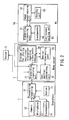
- FIG. 2 is a function block of the home network system of the first embodiment.
- the doorphone 1 comprises the button 11, camera 12, microphone 13 and loudspeaker 14, as described above.
- the doorphone 1 comprises a transmitting/receiving unit 15 configured to transmit or receive various kinds of data from the home server 2.
- the camera 12 starts recording an image and the microphone 13 becomes ready for input of voice.
- the recorded image and the input voice are transmitted to the home server 2 by way of the transmitting/receiving unit 15.
- the home server 2 comprises a transmitting/receiving unit 21, a user position determining unit 22, a device selecting unit 23 and a storage unit 24 for storing positional information regarding video/audio devices.
- the transmitting/receiving unit 21 exchange data with the doorphone 1 and manages the communications the human sensors 3 and personal computer 5a perform via the LAN 100. Upon receipt of image data and voice data from the doorphone 1, the transmitting/receiving unit 21 notifies the user position determining unit 22 of the reception of the data.
- the user position determining unit 22 checks in which room the user is present, by acquiring information representing how the human sensors 3 of the respective rooms A, B and D sense. The information is acquired by way of the transmitting/receiving unit 21.
- the function of the human sensors 3 can be realized in many ways. For example, the user 6 may be sensed by monitoring whether or not an emitted infrared ray is intercepted or by sensing sound or a temperature that has exceeded a predetermined level.
- the user position determining unit 22 notifies the device selecting unit 23 of the human sensor 3 that is sensing the user 6.
- the user position determining unit 22 causes the transmitting/receiving unit 21 to transmit a user-absence message to the doorphone 1.
- the device selecting unit 23 selects a destination device to which the image data and voice data entered from the doorphone 1 should be sent.
- FIG. 3 shows an example of positional information the storage unit 24 stores.
- the positional information the storage unit 24 stores is in the form of a table and includes fields corresponding to "sensor ID”, “device ID (address)", "video reproduction” and "audio reproduction". Since a notification indicating that the human sensor 3 of room B is sensing the user 6 is received from the user position determining unit 22 at the time, the device selecting unit 23 refers to this positional information and determines that the personal computer 5a is suitable for use as a destination device to which the image data and voice data from the doorphone 1 should be sent.
- the device selecting unit 23 recognizes that the personal computer 5a has both the video reproduction function and the audio reproduction function.
- the device selecting unit 23 notifies the transmitting/receiving unit 21 that the image data and the voice data transmitted from the doorphone 1 are to be sent to the personal computer 5a.
- the transmitting/receiving unit 21 Upon receipt of this notification from the device selecting unit 23, the transmitting/receiving unit 21 transfers the image data and voice data, which have been transmitted from the doorphone 1, to the personal computer 5a.
- the personal computer 5a serving as a destination device comprises a transmitting/receiving unit 51, an image superimposing unit 52, a display unit 53, a loudspeaker 54 and an environment setting unit 55.
- the transmitting/receiving unit 51 controls the communications the home server 2 and the personal computer 5a perform through the LAN 100. Upon receipt of the image data and voice data transmitted from the doorphone 1, the transmitting/receiving unit 51 transmits the image data to the image superimposing unit 52 and the voice data to the loudspeaker 54.
- the image superimposing unit 52 performs image processing so that the image transmitted from the doorphone 1 is superimposed on part (e.g., at the upper right corner) of the image data shown on the display unit 53.
- image processing the image of the visitor who depressed the button 11 of the doorphone 1 is displayed on part of the display unit 53.
- the image of the visitor may be displayed on the entirety of the display unit 53, replacing the image data that has been shown until then.
- the voice of the visitor is output from the loudspeaker 54.
- the network system detects the presence of the user 6 without reference to the room the user is present. Through the television receiver 4 or personal computer 5a, 5b of the room where the user 6 is present, the image and voice of the visitor are presented to the user 6.
- the environment setting unit 55 of the personal computer 5a shown in FIG. 2 enables selection of one of the following two operation environment:
- the user can designate whether or not to superimpose image data (which is provided by the doorphone 1 and transferred by the home server 2) on the presently-displayed image data.
- the image superimposing unit 52 executes image processing for the image superimposition described above.
- the image processing is not executed, and only the voice is output from the loudspeaker 54.
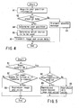
- FIG. 4 is a flowchart illustrating how the home server 2 operates in the home network system of the present embodiment.
- the user position determining unit 22 acquires user position information through the transmitting/receiving unit 21 (Step A1).
- the user position information represents how the human sensors 3 of the rooms sense a user 6. If none of the human sensors 3 sense the user 6 (NO in Step A2), then the user position determining unit 21 transmits an absence message (voice data) to the doorphone 1 by way of the transmitting/receiving unit 21 (Step A3) .
- the user position determining unit 22 determines that the room where that human sensor 3 is installed indicates the position of the user. Then, the user position determining unit 22 notifies the device selecting unit 23 of the ID assigned to the human sensor 3 (Step A4).
- the device selecting unit 23 Upon receipt of this notification, the device selecting unit 23 refers to the information the storage unit 24 stores and recognizes which device (the television receiver 4, personal computer 5a, or personal computer 5b) is associated with the human sensor 3. The device determined as being associated with the human sensor 3 is a destination video/audio device to which the image data and audio data should be sent. Then, the device selecting unit 23 sends a command to the transmitting/receiving unit 21 so that the image data and voice data the transmitting/receiving unit 21 receives from the doorphone 1 may be sent to the destination video/audio device (Step A5).
- the transmitting/receiving unit 21 Upon receipt of the command, the transmitting/receiving unit 21 transmits the image data and voice data, which are from the doorphone 1, to the video/audio device selected by the device selecting unit 23 (Step A6).
- FIG. 5 is a flowchart illustrating how personal computer 5a operates in the home network system.
- the transmitting/receiving unit 51 checks if the main power supply is ON (Step B1). If the main power supply is not ON (NO in Step B1), then the transmitting/receiving unit 51 checks if the main power supply can be turned on in response to a request (Step B2).
- Step B2 If the check shows that the main power supply can be turned on (YES in Step B2), the transmitting/receiving unit 51 sends the image data to the image superimposing unit 52 and the voice data to the loudspeaker 54. Since no image data is displayed in this case, the display unit 53 displays only the image from the doorphone 1 in a full-screen mode (Step B3). On the other hand, if the check shows that the main power supply cannot be turned on (NO in Step B2), the transmitting/receiving unit 51 does not display the image data or output the voice data.
- the transmitting/receiving unit 51 immediately supplies the image data to the image superimposing unit 52 and supplies the voice data to the loudspeaker 54.
- the image superimposing unit 52 checks if the image superimposition can be performed (Step B4). If this is the case (YES in Step B4), the image superimposing unit 52 executes image processing to superimpose the image data from the doorphone 1 on the image that is being displayed (Step B5). If the image superimposition is disabled (NO in Step B4), the image processing is not executed, and only the voice is output from the loudspeaker 54 (Step B6) .
- the home network-system identifies the position of the user 6 by means of the human sensors 3, and selects a video/audio device suited to the position of the user 6. In this manner, the home network system enables automatic selection of a data transfer destination that is suitable to the situation.
- the device selecting unit 23 may select all video/audio devices associated with the human sensors 3, as destination devices. Alternatively, the device selecting unit 23 may select one of the video/audio devices based on a predetermined priority order.
- the doorphone 1 may have a function of calling a particular person, and the human sensors 3 may have a function of sensing that particular person.
- a visitor can calla particular person when this person is in the house together with his or her family members, and only the video/audio device installed in the room where the particular person is present, can be selected as a destination device.
- the particular person can be called, for example, by providing a plurality of buttons 11 corresponding to family members, and the particular person can be identified, for example, by reading a noncontact IC tag each family member wears.
- the method of calling and identifying the particular person is not limited to this, and any method is applicable as long as it meets the purpose.
- FIG. 6 illustrates a home network system according to the second embodiment of the present invention.
- the home network system of the second embodiment differs from that of the first embodiment in that a home server 2 is connected not to a doorphone 1 but to a public telephone network 200.
- a user 6 carries a portable phone 7 that communicates with the home server 2 by wireless, and the home server 2 receives a call from a videophone 8 of the public telephone network 200.
- the home server 2 transfers image data on the image of the person who uses the videophone 8 (who will be hereinafter referred to simply as a communication party 9) to the video/audio device installed in the room where the user 6 is present.
- the home server 2 transfers the voice data on the voice uttered by the communication party 9 to the portable phone 7.
- the home server 2 receives voice data on the voice (uttered by the user 6 and transmitted from the portable phone 7) and transmits this voice data to the videophone 8 over the public telephone network 200.
- the home network system enables the user 6 to communicate with the communication party 9 through the portable phone without reference to the room the user is in at the time, and the user 6 can watch the image of the party 9 displayed on the video/audio device of the room during communication. It is assumed here that the user 6 is in room A and is watching a TV program on the television receiver 4.
- the portable phone 7 is an electronic device working on a wireless public telephone network, and is singly capable of communicating with another device through the wireless public telephone network.
- the portable phone 7 serves as a communication terminal that performs the wireless communication based on the Bluetooth(R) standards with the home server 2.
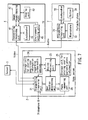
- FIG. 7 is a function block of the home network system of the second embodiment.
- the home server 2 of the network system comprises a storage unit 25 (which stores portable phone information) and a phone-answering unit 26, in addition to the structural elements described in connection with the first embodiment.
- FIG. 8 shows an example of telephone information which the storage unit 25 of the home network system of the second embodiment stores.
- the portable phone information the storage unit 25 stores is in the form of a table and includes fields corresponding to "user ID" and "portable phone ID".
- the network system of the second embodiment comprises human sensors 3 that identify persons by reading noncontact IC tags. Therefore, a notification the device selecting unit 23 receives from a user position determining unit 22 includes information indicating that one of the human sensors 3 is sensing a specified user 6. Upon receipt of this notification, the device selecting unit 23 refers to the positional information a storage unit 24 stores to identify the positions of video/audio devices, and determines that a television receiver 4 is suitable for use as a destination device to which the image data from the videophone 8 should be sent. Simultaneous with this, the device selecting unit 23 refers to the portable phone information the storage unit 25 stores to identify the portable phones, and determines that the portable phone 7 is suitable for use as a destination device to which the voice data from the videophone 8 should be sent.
- the device selecting unit 23 notifies the transmitting/receiving unit 21 that a call received through the public telephone network 200 should be transferred to the portable phone 7. Thereafter, the device selecting unit 23 notifies the transmitting/receiving unit 21 that it should transfer the image data from the videophone 8 to the television receiver 4, and that it should serve as a relay for relaying the voice data exchanged between the videophone 8 and the portable phone 7.
- the user position determining unit 22 notifies the phone-answering unit 26 of this state.
- the phone-answering unit 26 sends an absence message to the videophone 8 by way of the transmitting/receiving unit 21.
- the phone-answering unit 26 receives a message the videophone 8 sends through the transmitting/receiving unit 21, and records the received message.
- the portable phone 7, which receives a call-notification message from the transmitting/receiving unit 21, comprises a transmitting/receiving unit 71, a loudspeaker 72, a microphone 73 and a button 74.
- the transmitting/receiving unit 71 controls the communications the portable phone 7 and the home server 2 perform through the LAN 100. Upon receipt of a call notification, the transmitting/receiving unit 71 outputs a ringing sound-generating signal to the loudspeaker 72. Where the user 6 wishes to accept the call, the user 6 depresses the button 74 in response to the ringing signal, thereby sending a call-accepting notification to the home server 2.
- the transmitting/receiving unit 21 of the home server 2 informs the public telephone network 200 of the user's acceptance of the call. Then, the transmitting/receiving unit 21 transfers the image data transmitted from the videophone 8 to the television receiver 4, and transfers the voice data transmitted from the videophone 8 to the portable phone 7. In the meantime, the voice data entered by use of the microphone 73 is transmitted from the portable phone 7 to the home server 2. Upon receipt of the voice data from the portable phone 7, the home server 2 transmits it to the videophone 8 over the public telephone network 200.
- the television receiver 4 to which the image data is transferred, comprises a transmitting/receiving unit 41, an image superimposing unit 42, a display unit 43, a loudspeaker 44 and an environment setting unit 45. These units correspond to the transmitting/receiving unit 51, image superimposing unit 52, display unit 53, loudspeaker 54 and environment setting unit 55 of the personal computer 5a shown in FIG. 2.
- FIG. 9 is a flowchart illustrating how the home server 2 operates in the home network system of the second embodiment.
- the user position determining unit 22 Upon reception of the notification of an incoming call from the public phone network 200, the user position determining unit 22 acquires user position information through the transmitting/receiving unit 21 (Step C1) The user position information represents how the human sensors 3 of the rooms sense a user 6. If none of the human sensors 3 sense the user 6 (NO in Step C2), then the user position determining unit 21 transmits an absence message to the phone-answering unit 26. In response to this, the phone-answering unit 26 transmits the absence message to the videophone 8 by way of the transmitting/receiving unit 21, and receives and records a message transmitted from the videophone 8 by way of the transmitting/receiving unit 21 (Step C3).
- the user position determining unit 22 determines that the room where that human sensor 3 is installed indicates the position of the user 6. Then, the user position determining unit 22 notifies the device selecting unit 23 of the ID assigned to the human sensor 3 and the ID assigned to the user 6 (Step C4).
- the device selecting unit 23 Upon receipt of this notification, the device selecting unit 23 refers to the positional information the storage unit 24 stores and recognizes which device (the television receiver 4, personal computer 5a, or personal computer 5b) is associated with the human sensor 3. Furthermore, the device selecting unit 23 refers to the phone information the storage unit 25 stores to identify the portable phone (Step C5).
- the device selecting unit 23 informs the transmitting/receiving unit 21 that a notification of an incoming call from the public telephone network 200 should be sent to the portable phone 7.
- the transmitting/receiving unit 21 transmits the notification of the incoming call to the portable phone 7 (Step C6).
- Step C7 If a call-acceptance notification is transmitted from the portable phone 7 in response to the incoming call notification (YES in Step C7), the transmitting/receiving unit 21 starts two kinds of processing: one for transferring the image data, transmitted from the videophone 8, to the television receiver 4; and the other for relaying the voice data exchanged between the videophone 8 and the portable phone 7 (Step C8). If the call-acceptance notification is not transmitted even after a predetermined period of time (NO in Step C7), a notification indicating this state is sent to the phone-answering unit 26.
- the phone-answering unit 26 Upon receipt of this notification, the phone-answering unit 26 transmits an absence message to the videophone 8 by way of the transmitting/receiving unit 21, and receives and records a message transmitted from the videophone 8 by way of the transmitting/receiving unit 21 (Step C3).
- the home network system identifies the position of the user 6 by means of the human sensors 3, and selects video/audio device suited to the position of the user 6. In this manner, the home network system enables automatic selection of a data transfer destination that is suitable to the situation.
Abstract
A doorphone (1) is provided with a camera,
a microphone, a button serving as an input device, and
a loudspeaker serving as an output device. When a
visitor pushes the button, the camera starts recording
an image and the microphone becomes ready for input
of voice. The doorphone (1) sends the recorded image
and the input voice to an operation panel (10). The
doorphone (1) sends the recorded image and the input
voice to the home server (2) as well. Upon reception
of the image and the voice, the home server (2)
recognizes which sensor (3) senses a user (6) through
the use of a LAN (100), and selects a video/audio
device (e.g., a personal computer (5a)) associated
with that sensor (3) as a data destination device.
The image and voice received from the doorphone (1) are
transferred to the selected video/audio device through
the LAN (100).
Description
The present invention relates to a network system,
a server apparatus and a communication method.
Home networks in which home-use electronic devices
are connected together have become popular in recent
years, as communication technology and information
processing technology advance. Installed indoors, home
networks enable the electronic devices of different
rooms to be organically coupled together, creating
added values.
In the home network system described in Jpn. Pat.
Appln. KOKAI Publication No. 2002-135745, a home server
receives external broadcast signals and transmits them
to the display device of each room. The user can
therefore arrange the electronic devices without being
restricted by antenna wires and enjoy desired broadcast
service in a desired room.
In the network system described above, the home
server transmits external broadcast signals to the
display device in each room in response to a request
the display device makes. In other words, the
destination display device to which the external
broadcast signals are transmitted is determined by
operations the destination display device performs.
There may be a case where the user wishes
automatic transmission wherein various kinds of data
the home server receives are automatically transmitted
to the electronic device of the room where the user is
in at the time. In the above network system, however,
the home server merely identifies the destination
display device to which the signals or data should
be sent; it does not have a function of positively
selecting the destination display device.
The present invention has been made under these
circumstances, and an object of the present invention
is to provide a network system, a server apparatus
and a communication method, which enable selecting
an optimal data transmission destination device desired
at any given time.
To achieve this object, the present invention
' provides a network system, having human sensors, which
transfers data from a first device to second devices by
way of a server device, the server device characterized
by comprising a positional information storage unit
which stores positional information representing
correspondence between the human sensors and the second
devices, a transfer destination selecting unit
selecting one of the second devices as a destination
device to which the data transmitted from the first
device should be sent, based on sensing information
from the human sensors and the positional information
stored in the positional information storage unit, and
a data transfer unit transferring data from the first
device to the one of the second devices which is
selected by the transfer designation selecting unit.
Owing to these features, the present invention can
provide a network system, a server apparatus and a
communication method, which enable selecting an optimal
data transmission destination device desired at any
given time.
This summary of the invention does not necessarily
describe all necessary features so that the invention
may also be a sub-combination of these described
features.
The invention can be more fully understood from
the following detailed description when taken in
conjunction with the accompanying drawings, in which:
The first embodiment of the present invention will
be described. FIG. 1 is a diagram illustrating a home
network system according to the first embodiment of the
present invention.
The home network system comprises a doorphone 1
(i.e., an intercom installed at the front door of
a house), a home server 2, human sensors 3 (which sense
the presence or absence of a user), a television
receiver 4, and personal computers 5a and 5b. The home
server 2 is an electronic device that plays the most
important role of the system, and provides various
kinds of service to the personal computers 5a and 5b,
such as the recording/reproduction of television
broadcasts, the browsing of Internet web sites; etc.
A local area network (LAN) 100 installed indoors
connects the home server 2, the human sensors 3, the
television receiver 4 and the personal computers 5a and
5b to one another. The doorphone 1 is connected to the
home server 2.
The doorphone 1 comprises an input device such as
a camera, a microphone and a push button, and an output
device such as a loudspeaker. When a visitor pushes
the button, the camera starts recording an image and
the microphone becomes ready for input of voice.
The recorded image and the input voice are transmitted
to an operation panel 10. The operation panel 10
comprises an input device such as a microphone and
a push button, a monitor and an output device such as
a loudspeaker. The image recorded by the camera of
the doorphone 1 is displayed on the monitor of the
operation panel 10, and the voice input by the
microphone of the doorphone 1 is output from the
loudspeaker of the operation panel 10. When a resident
(who will be hereinafter referred to simply as a user
6) pushes the button of the operation panel 10, the
microphone of the operation panel 10 becomes ready for
input of voice, and the loudspeaker of the doorphone 1
outputs the input voice.
The image and voice the doorphone 1 records are
transmitted to the home server 2 as well. The home
server 2 can appropriately transfer the image and voice
to the television receiver 4 and the personal computers
5a and 5b, according to the situation. A detailed,
description will be given of this point.
Let us assumed that the house has four rooms A-D,
and the operation panel 10 connected to the doorphone 1
is located in room C. The home server 2 is also
located in room C. The television receiver 4 is
located in room A, and personal computers 5a and 5b are
located in rooms B and D, respectively. The user is in
room B and operates personal computer 5a.
When a visitor comes to the house, the home server
2 receives the image and voice from the doorphone 1 and
transmits them to personal computer 5a of room B where
the user is present at the time. The principles
underlying the communication control the home server 2
executes will be described, referring to FIG. 2.
FIG. 2 is a function block of the home network system
of the first embodiment.
The doorphone 1 comprises the button 11, camera
12, microphone 13 and loudspeaker 14, as described
above. In addition, the doorphone 1 comprises a
transmitting/receiving unit 15 configured to transmit
or receive various kinds of data from the home server
2. When the visitor pushes the button 11, the camera
12 starts recording an image and the microphone 13
becomes ready for input of voice. The recorded image
and the input voice are transmitted to the home server
2 by way of the transmitting/receiving unit 15.
The home server 2 comprises a transmitting/receiving unit 21, a user position determining unit 22,
a device selecting unit 23 and a storage unit 24 for
storing positional information regarding video/audio
devices.
The transmitting/receiving unit 21 exchange data
with the doorphone 1 and manages the communications the
human sensors 3 and personal computer 5a perform via
the LAN 100. Upon receipt of image data and voice data
from the doorphone 1, the transmitting/receiving unit
21 notifies the user position determining unit 22 of
the reception of the data.
The user position determining unit 22 checks
in which room the user is present, by acquiring
information representing how the human sensors 3 of the
respective rooms A, B and D sense. The information is
acquired by way of the transmitting/receiving unit 21.
The function of the human sensors 3 can be realized in
many ways. For example, the user 6 may be sensed by
monitoring whether or not an emitted infrared ray is
intercepted or by sensing sound or a temperature that
has exceeded a predetermined level. The user position
determining unit 22 notifies the device selecting unit
23 of the human sensor 3 that is sensing the user 6.
If none of the human sensors 3 sense the user 6,
the user position determining unit 22 causes the
transmitting/receiving unit 21 to transmit a user-absence
message to the doorphone 1.
Based on the notification from the user position
determining unit 22 and the positional information
stored in the storage,unit 24, the device selecting
unit 23 selects a destination device to which the image
data and voice data entered from the doorphone 1 should
be sent. FIG. 3 shows an example of positional
information the storage unit 24 stores.
As FIG. 3 shows, the positional information
the storage unit 24 stores is in the form of a table
and includes fields corresponding to "sensor ID",
"device ID (address)", "video reproduction" and "audio
reproduction". Since a notification indicating that
the human sensor 3 of room B is sensing the user 6 is
received from the user position determining unit 22 at
the time, the device selecting unit 23 refers to this
positional information and determines that the personal
computer 5a is suitable for use as a destination device
to which the image data and voice data from the
doorphone 1 should be sent.
Then, the device selecting unit 23 recognizes
that the personal computer 5a has both the video
reproduction function and the audio reproduction
function. The device selecting unit 23 notifies the
transmitting/receiving unit 21 that the image data and
the voice data transmitted from the doorphone 1 are to
be sent to the personal computer 5a.
Upon receipt of this notification from the device
selecting unit 23, the transmitting/receiving unit 21
transfers the image data and voice data, which have
been transmitted from the doorphone 1, to the personal
computer 5a.
The personal computer 5a serving as a destination
device comprises a transmitting/receiving unit 51,
an image superimposing unit 52, a display unit 53,
a loudspeaker 54 and an environment setting unit 55.
The transmitting/receiving unit 51 controls the
communications the home server 2 and the personal
computer 5a perform through the LAN 100. Upon receipt
of the image data and voice data transmitted from
the doorphone 1, the transmitting/receiving unit 51
transmits the image data to the image superimposing
unit 52 and the voice data to the loudspeaker 54.
The image superimposing unit 52 performs image
processing so that the image transmitted from the
doorphone 1 is superimposed on part (e.g., at the upper
right corner) of the image data shown on the display
unit 53. By this image processing, the image of the
visitor who depressed the button 11 of the doorphone 1
is displayed on part of the display unit 53. The image
of the visitor may be displayed on the entirety of the
display unit 53, replacing the image data that has been
shown until then.
The voice of the visitor is output from the
loudspeaker 54. As can be seen from this, the network
system detects the presence of the user 6 without
reference to the room the user is present. Through the
television receiver 4 or personal computer 5a, 5b of
the room where the user 6 is present, the image and
voice of the visitor are presented to the user 6.
With respect to the image data and voice data.
transmitted from the doorphone 1, the environment
setting unit 55 of the personal computer 5a shown in
FIG. 2 enables selection of one of the following two
operation environment:
In this operation environment, the user can
designate whether or not to superimpose image data
(which is provided by the doorphone 1 and transferred
by the home server 2) on the presently-displayed image
data. When the operation environment is set that
the superposition of images is enabled, the image
superimposing unit 52 executes image processing for
the image superimposition described above. When the
operation environment is set that the superposition
of images is disabled, the image processing is not
executed, and only the voice is output from the
loudspeaker 54.
FIG. 4 is a flowchart illustrating how the home
server 2 operates in the home network system of the
present embodiment.
When image data and voice data are transmitted,
the user position determining unit 22 acquires user
position information through the transmitting/receiving
unit 21 (Step A1). The user position information
represents how the human sensors 3 of the rooms sense a
user 6. If none of the human sensors 3 sense the user
6 (NO in Step A2), then the user position determining
unit 21 transmits an absence message (voice data) to
the doorphone 1 by way of the transmitting/receiving
unit 21 (Step A3) .
If one of the human sensors 3 senses the user 6
(YES in Step A2), the user position determining unit 22
determines that the room where that human sensor 3 is
installed indicates the position of the user. Then,
the user position determining unit 22 notifies the
device selecting unit 23 of the ID assigned to the
human sensor 3 (Step A4).
Upon receipt of this notification, the device
selecting unit 23 refers to the information the storage
unit 24 stores and recognizes which device (the
television receiver 4, personal computer 5a, or
personal computer 5b) is associated with the human
sensor 3. The device determined as being associated
with the human sensor 3 is a destination video/audio
device to which the image data and audio data should
be sent. Then, the device selecting unit 23 sends
a command to the transmitting/receiving unit 21 so that
the image data and voice data the
transmitting/receiving unit 21 receives from the
doorphone 1 may be sent to the destination video/audio
device (Step A5).
Upon receipt of the command, the transmitting/receiving unit 21 transmits the image data and voice
data, which are from the doorphone 1, to the
video/audio device selected by the device selecting
unit 23 (Step A6).
FIG. 5 is a flowchart illustrating how personal
computer 5a operates in the home network system.
When image data and voice data are transmitted,
the transmitting/receiving unit 51 checks if the main
power supply is ON (Step B1). If the main power supply
is not ON (NO in Step B1), then the transmitting/receiving unit 51 checks if the main power supply can
be turned on in response to a request (Step B2).
If the check shows that the main power supply
can be turned on (YES in Step B2), the transmitting/receiving unit 51 sends the image data to the image
superimposing unit 52 and the voice data to the
loudspeaker 54. Since no image data is displayed in
this case, the display unit 53 displays only the image
from the doorphone 1 in a full-screen mode (Step B3).
On the other hand, if the check shows that the main
power supply cannot be turned on (NO in Step B2),
the transmitting/receiving unit 51 does not display
the image data or output the voice data.
Where the main power supply is ON (YES in Step
B1), the transmitting/receiving unit 51 immediately
supplies the image data to the image superimposing unit
52 and supplies the voice data to the loudspeaker 54.
Upon receipt of the image data, the image superimposing
unit 52 checks if the image superimposition can be
performed (Step B4). If this is the case (YES in Step
B4), the image superimposing unit 52 executes image
processing to superimpose the image data from the
doorphone 1 on the image that is being displayed
(Step B5). If the image superimposition is disabled
(NO in Step B4), the image processing is not executed,
and only the voice is output from the loudspeaker 54
(Step B6) .
As described above, the home network-system
identifies the position of the user 6 by means of
the human sensors 3, and selects a video/audio device
suited to the position of the user 6. In this manner,
the home network system enables automatic selection of
a data transfer destination that is suitable to the
situation.
If the user's family members are also in the house
and located in different rooms from that of the user 6,
a plurality of human sensors 3 sense humans. In this
case, the device selecting unit 23 may select all
video/audio devices associated with the human sensors
3, as destination devices. Alternatively, the device
selecting unit 23 may select one of the video/audio
devices based on a predetermined priority order.
The doorphone 1 may have a function of calling
a particular person, and the human sensors 3 may have
a function of sensing that particular person. In this
case, a visitor can calla particular person when this
person is in the house together with his or her family
members, and only the video/audio device installed in
the room where the particular person is present, can
be selected as a destination device. The particular
person can be called, for example, by providing
a plurality of buttons 11 corresponding to family
members, and the particular person can be identified,
for example, by reading a noncontact IC tag each family
member wears. The method of calling and identifying
the particular person is not limited to this, and any
method is applicable as long as it meets the purpose.
The second embodiment of the present invention
will now be described. FIG. 6 illustrates a home
network system according to the second embodiment of
the present invention.
The home network system of the second embodiment
differs from that of the first embodiment in that
a home server 2 is connected not to a doorphone 1 but
to a public telephone network 200. A user 6 carries a
portable phone 7 that communicates with the home server
2 by wireless, and the home server 2 receives a call
from a videophone 8 of the public telephone network
200. The home server 2 transfers image data on the
image of the person who uses the videophone 8 (who will
be hereinafter referred to simply as a communication
party 9) to the video/audio device installed in the
room where the user 6 is present. Likewise, the home
server 2 transfers the voice data on the voice uttered
by the communication party 9 to the portable phone 7.
In addition, the home server 2 receives voice data on
the voice (uttered by the user 6 and transmitted from
the portable phone 7) and transmits this voice data to
the videophone 8 over the public telephone network 200.
As can be seen from the above, the home network
system enables the user 6 to communicate with the
communication party 9 through the portable phone
without reference to the room the user is in at the
time, and the user 6 can watch the image of the party 9
displayed on the video/audio device of the room during
communication. It is assumed here that the user 6
is in room A and is watching a TV program on the
television receiver 4.
The portable phone 7 is an electronic device
working on a wireless public telephone network, and is
singly capable of communicating with another device
through the wireless public telephone network. When
used for communicating with the videophone 8 through
the home server 2, the portable phone 7 serves as
a communication terminal that performs the wireless
communication based on the Bluetooth(R) standards with
the home server 2.
FIG. 7 is a function block of the home network
system of the second embodiment.
As FIG. 7 shows, the home server 2 of the network
system comprises a storage unit 25 (which stores
portable phone information) and a phone-answering unit
26, in addition to the structural elements described
in connection with the first embodiment. FIG. 8 shows
an example of telephone information which the storage
unit 25 of the home network system of the second
embodiment stores.
As FIG. 8 shows, the portable phone information
the storage unit 25 stores is in the form of a table
and includes fields corresponding to "user ID" and
"portable phone ID".
The network system of the second embodiment
comprises human sensors 3 that identify persons by
reading noncontact IC tags. Therefore, a notification
the device selecting unit 23 receives from a user
position determining unit 22 includes information
indicating that one of the human sensors 3 is sensing
a specified user 6. Upon receipt of this notification,
the device selecting unit 23 refers to the positional
information a storage unit 24 stores to identify the
positions of video/audio devices, and determines that
a television receiver 4 is suitable for use as a
destination device to which the image data from the
videophone 8 should be sent. Simultaneous with this,
the device selecting unit 23 refers to the portable
phone information the storage unit 25 stores to
identify the portable phones, and determines that the
portable phone 7 is suitable for use as a destination
device to which the voice data from the videophone 8
should be sent. Then, the device selecting unit 23
notifies the transmitting/receiving unit 21 that a
call received through the public telephone network
200 should be transferred to the portable phone 7.
Thereafter, the device selecting unit 23 notifies the
transmitting/receiving unit 21 that it should transfer
the image data from the videophone 8 to the television
receiver 4, and that it should serve as a relay for
relaying the voice data exchanged between the
videophone 8 and the portable phone 7.
Where none of the human sensors 3 sense the user
6, the user position determining unit 22 notifies the
phone-answering unit 26 of this state. In response,
the phone-answering unit 26 sends an absence message to
the videophone 8 by way of the transmitting/receiving
unit 21. Then, the phone-answering unit 26 receives
a message the videophone 8 sends through the
transmitting/receiving unit 21, and records the
received message.
The portable phone 7, which receives a call-notification
message from the transmitting/receiving
unit 21, comprises a transmitting/receiving unit 71,
a loudspeaker 72, a microphone 73 and a button 74.
The transmitting/receiving unit 71 controls the
communications the portable phone 7 and the home server
2 perform through the LAN 100. Upon receipt of a call
notification, the transmitting/receiving unit 71
outputs a ringing sound-generating signal to the
loudspeaker 72. Where the user 6 wishes to accept the
call, the user 6 depresses the button 74 in response to
the ringing signal, thereby sending a call-accepting
notification to the home server 2.
Upon receipt of the call-accepting notification,
the transmitting/receiving unit 21 of the home server 2
informs the public telephone network 200 of the user's
acceptance of the call. Then, the transmitting/receiving unit 21 transfers the image data transmitted
from the videophone 8 to the television receiver 4,
and transfers the voice data transmitted from the
videophone 8 to the portable phone 7. In the meantime,
the voice data entered by use of the microphone 73 is
transmitted from the portable phone 7 to the home
server 2. Upon receipt of the voice data from the
portable phone 7, the home server 2 transmits it to the
videophone 8 over the public telephone network 200.
The television receiver 4, to which the image data
is transferred, comprises a transmitting/receiving unit
41, an image superimposing unit 42, a display unit 43,
a loudspeaker 44 and an environment setting unit 45.
These units correspond to the transmitting/receiving
unit 51, image superimposing unit 52, display unit 53,
loudspeaker 54 and environment setting unit 55 of the
personal computer 5a shown in FIG. 2.
FIG. 9 is a flowchart illustrating how the home
server 2 operates in the home network system of the
second embodiment.
Upon reception of the notification of an incoming
call from the public phone network 200, the user
position determining unit 22 acquires user position
information through the transmitting/receiving unit 21
(Step C1) The user position information represents
how the human sensors 3 of the rooms sense a user 6.
If none of the human sensors 3 sense the user 6 (NO in
Step C2), then the user position determining unit 21
transmits an absence message to the phone-answering
unit 26. In response to this, the phone-answering unit
26 transmits the absence message to the videophone 8 by
way of the transmitting/receiving unit 21, and receives
and records a message transmitted from the videophone 8
by way of the transmitting/receiving unit 21 (Step C3).
If one of the human sensors 3 senses the user 6
(YES in Step C2), the user position determining unit 22
determines that the room where that human sensor 3 is
installed indicates the position of the user 6. Then,
the user position determining unit 22 notifies the
device selecting unit 23 of the ID assigned to the
human sensor 3 and the ID assigned to the user 6
(Step C4).
Upon receipt of this notification, the device
selecting unit 23 refers to the positional information
the storage unit 24 stores and recognizes which device
(the television receiver 4, personal computer 5a, or
personal computer 5b) is associated with the human
sensor 3. Furthermore, the device selecting unit 23
refers to the phone information the storage unit 25
stores to identify the portable phone (Step C5).
Next, the device selecting unit 23 informs the
transmitting/receiving unit 21 that a notification of
an incoming call from the public telephone network 200
should be sent to the portable phone 7. Upon receipt
of this notification, the transmitting/receiving unit
21 transmits the notification of the incoming call to
the portable phone 7 (Step C6).
If a call-acceptance notification is transmitted
from the portable phone 7 in response to the incoming
call notification (YES in Step C7), the transmitting/receiving unit 21 starts two kinds of processing: one
for transferring the image data, transmitted from the
videophone 8, to the television receiver 4; and the
other for relaying the voice data exchanged between
the videophone 8 and the portable phone 7 (Step C8).
If the call-acceptance notification is not transmitted
even after a predetermined period of time (NO in Step
C7), a notification indicating this state is sent to
the phone-answering unit 26. Upon receipt of this
notification, the phone-answering unit 26 transmits
an absence message to the videophone 8 by way of the
transmitting/receiving unit 21, and receives and
records a message transmitted from the videophone 8 by
way of the transmitting/receiving unit 21 (Step C3).
As described above, the home network system
identifies the position of the user 6 by means of the
human sensors 3, and selects video/audio device suited
to the position of the user 6. In this manner, the
home network system enables automatic selection of
a data transfer destination that is suitable to the
situation.
Claims (13)
- A network system, having human sensors (3), which transfers data from a first device (1) to second devices (4, 5a, 5b) by way of a server device (2),
the server device characterized by comprising:a positional information storage unit (24) which stores positional information representing correspondence between the human sensors and the second devices;a transfer destination selecting unit (23) selecting one of the second devices as a destination device to which the data transmitted from the first device should be sent, based on sensing information from the human sensors and the positional information stored in the positional information storage unit; anda data transfer unit (21) transferring data from the first device to the one of the second devices which is selected by the transfer designation selecting unit. - The network system according to claim 1, characterized in that the first device is a doorphone having a camera and a microphone, and data on an image photographed by the camera and data on voice entered from the microphone are transmitted to the server device.
- The network system according to claim 1, characterized in that the human sensors are installed in different rooms respectively.
- The network system according to claim 1, characterized in that, when a plurality of human sensors sense humans, the transfer destination selecting unit of the server device selects all of the second devices which the positional information associates with the plurality of human sensors as destination devices to which the data transmitted from the first device should be sent.
- The network system according to claim 1, characterized in that the second devices comprising an environment setting unit (55) determining whether or not a power supply should be automatically turned on, when the data transmitted by the first device is received from the server device.
- The network system according to claim 1, characterized in that the second devices comprising:a display device (53); andan image superimposing unit (52) superposing image data, which is transmitted by the first device and transferred by the server device, on image data shown on the display device.
- The network system according to claim 6, characterized in that the second devices further comprising an environment setting unit (55) determining whether or not the image data transmitted by the first device should be superposed on the image data shown on the display device when the image data transmitted by the first device is transferred by the server device.
- The network system according to claim 1, characterized in that:the first device comprising a designating unit designating a data recipient;the human sensors comprising a identifying unit identifying a person; andthe transfer destination selecting unit of the server device selects one of the second devices which the positional information associates with a human sensor that senses a data recipient designated by the designating unit of the first device, as a destination device to which the data transmitted from the first device should be sent.
- The network system according to claim 1, characterized in that:the first device is a videophone that performs communications through the network by use of images;the human sensors comprising a identifying unit identifying a sensed person;the server device comprising a user information storage unit (25) which stores user information indicating a communication device used by the person identifiable by the human sensors; andthe data transfer unit of the server device transfers image data transmitted from the first device to the second device selected by the transfer destination selecting unit of the server device, transfers voice data transmitted from the first device to a communication device indicated by the user information storage unit as a device using the person identified by the human sensor, and transfers the voice data transmitted from the communication device to the first device.
- A communication method for transferring data from a first device to second devices, characterized by comprising the steps of:acquiring (A1) sensing information on human sensors;selecting (A2) one of the second devices as a destination device to which the data transmitted from the first device should be sent, based on the sensing information and positional information representing correspondence between the human sensors and the second devices; andtransferring (A6) data from the first device to the one of the selected second devices.
- The communication method according to claim 10, characterized in that, when a plurality of human sensors sense humans, the selecting one of the second devices selects all of the second devices which the positional information associates with the plurality of human sensors, as destination devices to which the data transmitted from the first device should be sent.
- The communication method according to claim 10, characterized in that the selecting one of the second devices selects one of the second devices which the positional information associates with a human sensor that senses a data recipient designated by the first device, as a destination device to which the data transmitted from the first device should be sent.
- The communication method according to claim 10, characterized in that the transferring data transfers image data transmitted from the first device to the selected second device, transfers voice data transmitted from the first device to a communication device using a person identified by the human sensor based on user information indicating a communication device used by a person identifiable by the sensor, and transfers the voice data transmitted from the communication device to the first device.
Applications Claiming Priority (2)
| Application Number | Priority Date | Filing Date | Title |
|---|---|---|---|
| JP2003053047 | 2003-02-28 | ||
| JP2003053047A JP2004266453A (en) | 2003-02-28 | 2003-02-28 | Network system, server equipment, and communication method |
Publications (1)
| Publication Number | Publication Date |
|---|---|
| EP1453247A2 true EP1453247A2 (en) | 2004-09-01 |
Family
ID=32767832
Family Applications (1)
| Application Number | Title | Priority Date | Filing Date |
|---|---|---|---|
| EP04001810A Withdrawn EP1453247A2 (en) | 2003-02-28 | 2004-01-28 | Network system, server apparatus, and communication method |
Country Status (5)
| Country | Link |
|---|---|
| US (1) | US20040170262A1 (en) |
| EP (1) | EP1453247A2 (en) |
| JP (1) | JP2004266453A (en) |
| KR (1) | KR20040077496A (en) |
| CN (1) | CN1525686A (en) |
Cited By (13)
| Publication number | Priority date | Publication date | Assignee | Title |
|---|---|---|---|---|
| WO2006041215A2 (en) * | 2004-10-14 | 2006-04-20 | Matsushita Electric Industrial Co., Ltd. | Door phone system |
| WO2006107058A1 (en) * | 2005-03-30 | 2006-10-12 | Matsushita Electric Industrial Co., Ltd. | Intercom system having networking functionality |
| WO2007084436A2 (en) * | 2006-01-17 | 2007-07-26 | Reality Mobile Llc | System and method for remote data acquisition and distribution |
| EP1821263A2 (en) * | 2006-02-02 | 2007-08-22 | Actip Limited | An access control system |
| WO2008005136A2 (en) * | 2006-07-06 | 2008-01-10 | Sbc Knowledge Ventures, L.P. | System and method of controlling access to an entrance |
| KR100802178B1 (en) | 2005-12-08 | 2008-02-12 | 한국전자통신연구원 | Intelligent phone-call service method in home network |
| KR100833130B1 (en) | 2006-12-29 | 2008-05-28 | 포스데이타 주식회사 | System and method for video phone using gateway |
| WO2011079877A1 (en) * | 2009-12-30 | 2011-07-07 | Nec Europe Ltd | Method and system for controlling devices and/or appliances being installed and/or implemented in a user network |
| CN103916457A (en) * | 2013-01-04 | 2014-07-09 | 三星电子株式会社 | Method Of Sharing Contents By Using Personal Cloud Device, And Electronic Device And Personal Cloud System |
| JP2016076762A (en) * | 2014-10-03 | 2016-05-12 | シャープ株式会社 | Network system, voice output method, server, apparatus, and voice output program |
| US9584775B2 (en) | 2013-07-18 | 2017-02-28 | BOT Home Automation, Inc. | Wireless entrance communication device |
| EP3680839A4 (en) * | 2017-09-05 | 2020-07-15 | Sony Corporation | Information processing device, information processing method, and program |
| US11044554B2 (en) | 2013-07-17 | 2021-06-22 | Amazon Technologies, Inc. | Auto-provisioning of wireless speaker devices for audio/video recording and communication devices |
Families Citing this family (58)
| Publication number | Priority date | Publication date | Assignee | Title |
|---|---|---|---|---|
| US6480510B1 (en) | 1998-07-28 | 2002-11-12 | Serconet Ltd. | Local area network of serial intelligent cells |
| US6549616B1 (en) | 2000-03-20 | 2003-04-15 | Serconet Ltd. | Telephone outlet for implementing a local area network over telephone lines and a local area network using such outlets |
| IL135744A (en) | 2000-04-18 | 2008-08-07 | Mosaid Technologies Inc | Telephone communication system over a single telephone line |
| IL144158A (en) | 2001-07-05 | 2011-06-30 | Mosaid Technologies Inc | Outlet for connecting an analog telephone set to a digital data network carrying voice signals in digital form |
| WO2003039150A1 (en) | 2001-10-11 | 2003-05-08 | Serconet Ltd. | Outlet with analog signal adapter, a method for use thereof and a network using said outlet |
| IL154921A (en) | 2003-03-13 | 2011-02-28 | Mosaid Technologies Inc | Telephone system having multiple distinct sources and accessories therefor |
| IL159838A0 (en) | 2004-01-13 | 2004-06-20 | Yehuda Binder | Information device |
| KR100561633B1 (en) * | 2004-09-22 | 2006-03-20 | 한국전자통신연구원 | Intelligent system and method of visitor confirming and communication service using mobile terminal |
| US8099313B2 (en) | 2004-09-22 | 2012-01-17 | Samsung Electronics Co., Ltd. | Method and system for the orchestration of tasks on consumer electronics |
| US8185427B2 (en) | 2004-09-22 | 2012-05-22 | Samsung Electronics Co., Ltd. | Method and system for presenting user tasks for the control of electronic devices |
| US8412554B2 (en) | 2004-09-24 | 2013-04-02 | Samsung Electronics Co., Ltd. | Method and system for describing consumer electronics using separate task and device descriptions |
| US7873058B2 (en) | 2004-11-08 | 2011-01-18 | Mosaid Technologies Incorporated | Outlet with analog signal adapter, a method for use thereof and a network using said outlet |
| US8510737B2 (en) * | 2005-01-07 | 2013-08-13 | Samsung Electronics Co., Ltd. | Method and system for prioritizing tasks made available by devices in a network |
| US8069422B2 (en) | 2005-01-10 | 2011-11-29 | Samsung Electronics, Co., Ltd. | Contextual task recommendation system and method for determining user's context and suggesting tasks |
| KR100643326B1 (en) * | 2005-02-22 | 2006-11-10 | 삼성전자주식회사 | Home network system and method for transmitting contents thereof |
| KR100672114B1 (en) * | 2005-03-02 | 2007-01-19 | 엘지전자 주식회사 | Method for controlling the front door phone in home network system |
| KR100664935B1 (en) | 2005-03-10 | 2007-01-04 | 삼성전자주식회사 | Apparatus and method for automatic redirection of multimedia contents play device |
| JP4631501B2 (en) * | 2005-03-28 | 2011-02-16 | パナソニック電工株式会社 | Home system |
| JP4611119B2 (en) * | 2005-05-31 | 2011-01-12 | シャープ株式会社 | Relay device and communication system |
| KR100706906B1 (en) | 2005-08-05 | 2007-04-12 | 에스케이 텔레콤주식회사 | Method for Remote Door Monitoring Using Video Telecommunication Network |
| JP4800738B2 (en) * | 2005-10-19 | 2011-10-26 | 京セラ株式会社 | Mobile phone |
| JP4586713B2 (en) * | 2005-11-15 | 2010-11-24 | 日本電気株式会社 | Telephone communication system |
| KR100762636B1 (en) * | 2006-02-14 | 2007-10-01 | 삼성전자주식회사 | System and nethod for controlling voice detection of network terminal |
| JP4893337B2 (en) * | 2007-01-26 | 2012-03-07 | 富士通株式会社 | Communication system and server device |
| US8756299B2 (en) * | 2007-06-13 | 2014-06-17 | Ajou University Industry—Academic Cooperation Foundation | Ubiquitous sensor network system and method of configuring the same |
| US8897433B2 (en) * | 2009-02-02 | 2014-11-25 | Alarmforce Industries Inc. | Security system with two-way communication and video |
| JP5541487B2 (en) * | 2009-11-27 | 2014-07-09 | ソニー株式会社 | Display control apparatus and display control system |
| DE102010014351A1 (en) * | 2010-04-09 | 2011-10-13 | S. Siedle & Söhne Telefon- und Telegrafenwerke OHG | House interphone operating method, involves flowing data streams with data in overlapping manner during data transmission, and decoupling flow of data streams from each other depending on data streams in different sections of transmission |
| US20110252328A1 (en) * | 2010-04-12 | 2011-10-13 | Jeyhan Karaoguz | System and method in a network controller for remotely monitoring and/or controlling devices |
| US9425981B2 (en) * | 2011-07-14 | 2016-08-23 | Colin Foster | Remote access control to residential or office buildings |
| CN102664008B (en) * | 2012-04-27 | 2014-11-19 | 上海量明科技发展有限公司 | Method, terminal and system for transmitting data |
| US9881474B2 (en) | 2012-09-21 | 2018-01-30 | Google Llc | Initially detecting a visitor at a smart-home |
| US9652912B2 (en) | 2012-09-21 | 2017-05-16 | Google Inc. | Secure handling of unsupervised package drop off at a smart-home |
| US9953514B2 (en) | 2012-09-21 | 2018-04-24 | Google Llc | Visitor feedback to visitor interaction with a doorbell at a smart-home |
| US10735216B2 (en) | 2012-09-21 | 2020-08-04 | Google Llc | Handling security services visitor at a smart-home |
| US9626841B2 (en) | 2012-09-21 | 2017-04-18 | Google Inc. | Occupant notification of visitor interaction with a doorbell at a smart-home |
| US9640055B2 (en) | 2012-09-21 | 2017-05-02 | Google Inc. | Interacting with a detected visitor at an entryway to a smart-home |
| US9600645B2 (en) | 2012-09-21 | 2017-03-21 | Google Inc. | Smart invitation handling at a smart-home |
| US9978238B2 (en) * | 2012-09-21 | 2018-05-22 | Google Llc | Visitor options at an entryway to a smart-home |
| US9960929B2 (en) | 2012-09-21 | 2018-05-01 | Google Llc | Environmental sensing with a doorbell at a smart-home |
| US9711036B2 (en) | 2012-09-21 | 2017-07-18 | Google Inc. | Leveraging neighborhood to handle potential visitor at a smart-home |
| US10332059B2 (en) | 2013-03-14 | 2019-06-25 | Google Llc | Security scoring in a smart-sensored home |
| US9959727B2 (en) | 2012-09-21 | 2018-05-01 | Google Llc | Handling visitor interaction at a smart-home in a do not disturb mode |
| GB2510804B (en) * | 2012-12-04 | 2016-06-22 | Moixa Energy Holdings Ltd | Distributed smart battery systems, methods and devices for electricity optimization |
| CN103970081B (en) * | 2013-02-04 | 2018-05-22 | 海尔集团公司 | Intelligent home furnishing control method, device and system |
| KR101467173B1 (en) | 2013-02-04 | 2014-12-01 | 주식회사 케이티 | Method and Apparatus of resource management of M2M network |
| KR101999231B1 (en) | 2013-02-27 | 2019-07-11 | 주식회사 케이티 | Control Unit for Vehicle Components And Mobile Terminal for Vehicle Control |
| CN105103569B (en) * | 2013-03-28 | 2017-05-24 | 杜比实验室特许公司 | Rendering audio using speakers organized as a mesh of arbitrary n-gons |
| KR101380608B1 (en) * | 2013-07-26 | 2014-04-10 | (주) 코콤 | Smart device based home network system and its control method |
| KR101687340B1 (en) * | 2013-09-12 | 2016-12-16 | 주식회사 케이티 | Method for setting home network operating environment and apparatus therefor |
| CN103473839A (en) * | 2013-09-13 | 2013-12-25 | 惠州Tcl移动通信有限公司 | Implementation method and implementation system of intelligent video access control system |
| KR101593115B1 (en) | 2013-10-15 | 2016-02-11 | 주식회사 케이티 | Method for monitoring legacy device status in home network system and home network system |
| CN103971428A (en) * | 2014-04-24 | 2014-08-06 | 四川长虹电器股份有限公司 | Door control monitoring method and door control monitoring system |
| CN106157520B (en) * | 2015-04-21 | 2018-08-14 | 信泰光学(深圳)有限公司 | Initiative Defence System |
| JP6192247B2 (en) * | 2016-06-27 | 2017-09-06 | シャープ株式会社 | Information notification system, information notification server, information notification method and program |
| JP6861052B2 (en) * | 2017-03-01 | 2021-04-21 | 大和ハウス工業株式会社 | system |
| US10558722B2 (en) * | 2017-03-31 | 2020-02-11 | Intel Corporation | Provision of on premise ambient service method and apparatus |
| KR102514128B1 (en) * | 2019-12-11 | 2023-03-24 | 엘지전자 주식회사 | An artificial intelligence apparatus for providing a connection between home devices and method thereof |
Family Cites Families (12)
| Publication number | Priority date | Publication date | Assignee | Title |
|---|---|---|---|---|
| US4601064A (en) * | 1983-01-13 | 1986-07-15 | Fisher Berkeley Corporation | Communication system |
| US4932050A (en) * | 1989-06-30 | 1990-06-05 | At&T Bell Laboratories | Proximity detection for telecommunications features |
| US5428388A (en) * | 1992-06-15 | 1995-06-27 | Richard von Bauer | Video doorbell system |
| US5363425A (en) * | 1992-06-29 | 1994-11-08 | Northern Telecom Limited | Method and apparatus for providing a personal locator, access control and asset tracking service using an in-building telephone network |
| US5515426A (en) * | 1994-02-28 | 1996-05-07 | Executone Information Systems, Inc. | Telephone communication system having a locator |
| US5612994A (en) * | 1995-02-22 | 1997-03-18 | Chen; Jhy-Ping | Interphone system |
| DE19511622A1 (en) * | 1995-03-30 | 1996-10-02 | Michael Wolf | Door answering machine |
| KR0164044B1 (en) * | 1995-09-25 | 1999-01-15 | 김광호 | Visitor recognition system and method |
| US5802147A (en) * | 1996-09-19 | 1998-09-01 | Siemens Business Communication Systems, Inc. | System and method for notifying a user of awaiting messages |
| US6370233B1 (en) * | 1999-08-03 | 2002-04-09 | Ameritech Corporation | Security system with call management functionality |
| US6594354B1 (en) * | 1999-11-05 | 2003-07-15 | Nortel Networks Limited | Method and apparatus for alert control on a communications system |
| US6912429B1 (en) * | 2000-10-19 | 2005-06-28 | Destiny Networks, Inc. | Home automation system and method |
-
2003
- 2003-02-28 JP JP2003053047A patent/JP2004266453A/en not_active Withdrawn
-
2004
- 2004-01-28 EP EP04001810A patent/EP1453247A2/en not_active Withdrawn
- 2004-02-18 US US10/779,737 patent/US20040170262A1/en not_active Abandoned
- 2004-02-26 KR KR1020040012908A patent/KR20040077496A/en active IP Right Grant
- 2004-02-27 CN CNA2004100072716A patent/CN1525686A/en active Pending
Cited By (24)
| Publication number | Priority date | Publication date | Assignee | Title |
|---|---|---|---|---|
| WO2006041215A3 (en) * | 2004-10-14 | 2006-07-13 | Matsushita Electric Ind Co Ltd | Door phone system |
| WO2006041215A2 (en) * | 2004-10-14 | 2006-04-20 | Matsushita Electric Industrial Co., Ltd. | Door phone system |
| US7636103B2 (en) | 2004-10-14 | 2009-12-22 | Panasonic Corporation | Door phone system |
| WO2006107058A1 (en) * | 2005-03-30 | 2006-10-12 | Matsushita Electric Industrial Co., Ltd. | Intercom system having networking functionality |
| KR100802178B1 (en) | 2005-12-08 | 2008-02-12 | 한국전자통신연구원 | Intelligent phone-call service method in home network |
| US7860994B2 (en) | 2006-01-17 | 2010-12-28 | Reality Mobile Llc | System and method for remote data acquisition and distribution |
| WO2007084436A2 (en) * | 2006-01-17 | 2007-07-26 | Reality Mobile Llc | System and method for remote data acquisition and distribution |
| US8041829B2 (en) | 2006-01-17 | 2011-10-18 | Reality Mobile Llc | System and method for remote data acquisition and distribution |
| US7949730B2 (en) | 2006-01-17 | 2011-05-24 | Reality Mobile Llc | System and method for remote data acquisition and distribution |
| WO2007084436A3 (en) * | 2006-01-17 | 2008-08-07 | Reality Mobile Llc | System and method for remote data acquisition and distribution |
| US7877502B2 (en) | 2006-01-17 | 2011-01-25 | Reality Mobile Llc | System and method for remote data acquisition and distribution |
| EP1821263A2 (en) * | 2006-02-02 | 2007-08-22 | Actip Limited | An access control system |
| EP1821263A3 (en) * | 2006-02-02 | 2010-03-17 | Actip Limited | An access control system |
| WO2008005136A2 (en) * | 2006-07-06 | 2008-01-10 | Sbc Knowledge Ventures, L.P. | System and method of controlling access to an entrance |
| WO2008005136A3 (en) * | 2006-07-06 | 2008-03-13 | Sbc Knowledge Ventures Lp | System and method of controlling access to an entrance |
| KR100833130B1 (en) | 2006-12-29 | 2008-05-28 | 포스데이타 주식회사 | System and method for video phone using gateway |
| WO2011079877A1 (en) * | 2009-12-30 | 2011-07-07 | Nec Europe Ltd | Method and system for controlling devices and/or appliances being installed and/or implemented in a user network |
| CN103916457A (en) * | 2013-01-04 | 2014-07-09 | 三星电子株式会社 | Method Of Sharing Contents By Using Personal Cloud Device, And Electronic Device And Personal Cloud System |
| US10447760B2 (en) | 2013-01-04 | 2019-10-15 | Samsung Electronics Co., Ltd. | Method of sharing contents by using personal cloud device, and electronic device and personal cloud system using the same |
| US11122103B2 (en) | 2013-01-04 | 2021-09-14 | Samsung Electronics Co., Ltd. | Method of sharing contents by using personal cloud device, and electronic device and personal cloud system using the same |
| US11044554B2 (en) | 2013-07-17 | 2021-06-22 | Amazon Technologies, Inc. | Auto-provisioning of wireless speaker devices for audio/video recording and communication devices |
| US9584775B2 (en) | 2013-07-18 | 2017-02-28 | BOT Home Automation, Inc. | Wireless entrance communication device |
| JP2016076762A (en) * | 2014-10-03 | 2016-05-12 | シャープ株式会社 | Network system, voice output method, server, apparatus, and voice output program |
| EP3680839A4 (en) * | 2017-09-05 | 2020-07-15 | Sony Corporation | Information processing device, information processing method, and program |
Also Published As
| Publication number | Publication date |
|---|---|
| CN1525686A (en) | 2004-09-01 |
| KR20040077496A (en) | 2004-09-04 |
| US20040170262A1 (en) | 2004-09-02 |
| JP2004266453A (en) | 2004-09-24 |
Similar Documents
| Publication | Publication Date | Title |
|---|---|---|
| EP1453247A2 (en) | Network system, server apparatus, and communication method | |
| US8848085B2 (en) | Photographing apparatus capable of communication with external apparatus and method of controlling the same | |
| US20120154508A1 (en) | Receiving and sending method of mobile tv phone and mobile tv phone terminal | |
| JPH098925A (en) | Automatic remote answering telephone set | |
| JP2002535930A (en) | System for transmitting a television program and additional information associated with the program to a plurality of customers, and a television receiver / display station and a method for displaying information associated with a standard television program | |
| WO2006013958A1 (en) | Function management system, management device, relay device, communication device, control method of communication device, control program of communication device, and computer-readable recording medium with recorded the control program | |
| KR20040033933A (en) | System and Method for Providing Real-time Image on Inspection and Survey Site | |
| JP4260591B2 (en) | Terminal device, home control device, and visit notification system | |
| JP5340249B2 (en) | Door phone device, door phone system, door phone device control method and program | |
| US20030204589A1 (en) | Data transmitting/receiving system, transmitting device, and data transmitting/receiving method | |
| JP2002135434A (en) | Interphone unit, interphone system, and storage medium with interphone software recorded thereon | |
| JP4680034B2 (en) | COMMUNICATION DEVICE, COMMUNICATION SYSTEM, COMMUNICATION DEVICE CONTROL PROGRAM, AND RECORDING MEDIUM CONTAINING COMMUNICATION DEVICE CONTROL PROGRAM | |
| JP2011135220A (en) | Intercom system | |
| JP6353801B2 (en) | Intercom system | |
| JP7297462B2 (en) | Visitor response system | |
| TWI716588B (en) | Call system, image signal acquisition device and call device | |
| JP2001298555A (en) | Device and system for information communication | |
| JP2003333198A (en) | Intercom system | |
| JP3908212B2 (en) | Interphone device, voice conversion method for interphone device, and voice conversion program for interphone device | |
| JP2002374358A (en) | Interphone system with imaging device, communication method for interphone with imaging device and portable communications terminal equipment and the portable communications terminal equipment | |
| JP2002125208A (en) | Videophone system | |
| JP2023018216A (en) | Intercom device and control method thereof | |
| JP2001309061A (en) | Answering system to visitor | |
| TWI403987B (en) | Wireless image-voice information transmision system and the controlling method thereof | |
| JPH08204836A (en) | Doorphone system |
Legal Events
| Date | Code | Title | Description |
|---|---|---|---|
| PUAI | Public reference made under article 153(3) epc to a published international application that has entered the european phase |
Free format text: ORIGINAL CODE: 0009012 |
|
| 17P | Request for examination filed |
Effective date: 20040128 |
|
| AK | Designated contracting states |
Kind code of ref document: A2 Designated state(s): AT BE BG CH CY CZ DE DK EE ES FI FR GB GR HU IE IT LI LU MC NL PT RO SE SI SK TR |
|
| AX | Request for extension of the european patent |
Extension state: AL LT LV MK |
|
| STAA | Information on the status of an ep patent application or granted ep patent |
Free format text: STATUS: THE APPLICATION HAS BEEN WITHDRAWN |
|
| 18W | Application withdrawn |
Effective date: 20060201 |