EP1452797B1 - Illumination apparatus - Google Patents
Illumination apparatus Download PDFInfo
- Publication number
- EP1452797B1 EP1452797B1 EP04004221A EP04004221A EP1452797B1 EP 1452797 B1 EP1452797 B1 EP 1452797B1 EP 04004221 A EP04004221 A EP 04004221A EP 04004221 A EP04004221 A EP 04004221A EP 1452797 B1 EP1452797 B1 EP 1452797B1
- Authority
- EP
- European Patent Office
- Prior art keywords
- light
- light source
- reflecting mirror
- illumination apparatus
- small
- Prior art date
- Legal status (The legal status is an assumption and is not a legal conclusion. Google has not performed a legal analysis and makes no representation as to the accuracy of the status listed.)
- Expired - Fee Related
Links
Images


Classifications
-
- F—MECHANICAL ENGINEERING; LIGHTING; HEATING; WEAPONS; BLASTING
- F21—LIGHTING
- F21V—FUNCTIONAL FEATURES OR DETAILS OF LIGHTING DEVICES OR SYSTEMS THEREOF; STRUCTURAL COMBINATIONS OF LIGHTING DEVICES WITH OTHER ARTICLES, NOT OTHERWISE PROVIDED FOR
- F21V5/00—Refractors for light sources
- F21V5/04—Refractors for light sources of lens shape
- F21V5/045—Refractors for light sources of lens shape the lens having discontinuous faces, e.g. Fresnel lenses
-
- F—MECHANICAL ENGINEERING; LIGHTING; HEATING; WEAPONS; BLASTING
- F21—LIGHTING
- F21V—FUNCTIONAL FEATURES OR DETAILS OF LIGHTING DEVICES OR SYSTEMS THEREOF; STRUCTURAL COMBINATIONS OF LIGHTING DEVICES WITH OTHER ARTICLES, NOT OTHERWISE PROVIDED FOR
- F21V13/00—Producing particular characteristics or distribution of the light emitted by means of a combination of elements specified in two or more of main groups F21V1/00 - F21V11/00
- F21V13/02—Combinations of only two kinds of elements
- F21V13/04—Combinations of only two kinds of elements the elements being reflectors and refractors
-
- F—MECHANICAL ENGINEERING; LIGHTING; HEATING; WEAPONS; BLASTING
- F21—LIGHTING
- F21V—FUNCTIONAL FEATURES OR DETAILS OF LIGHTING DEVICES OR SYSTEMS THEREOF; STRUCTURAL COMBINATIONS OF LIGHTING DEVICES WITH OTHER ARTICLES, NOT OTHERWISE PROVIDED FOR
- F21V14/00—Controlling the distribution of the light emitted by adjustment of elements
- F21V14/04—Controlling the distribution of the light emitted by adjustment of elements by movement of reflectors
-
- F—MECHANICAL ENGINEERING; LIGHTING; HEATING; WEAPONS; BLASTING
- F21—LIGHTING
- F21V—FUNCTIONAL FEATURES OR DETAILS OF LIGHTING DEVICES OR SYSTEMS THEREOF; STRUCTURAL COMBINATIONS OF LIGHTING DEVICES WITH OTHER ARTICLES, NOT OTHERWISE PROVIDED FOR
- F21V14/00—Controlling the distribution of the light emitted by adjustment of elements
- F21V14/06—Controlling the distribution of the light emitted by adjustment of elements by movement of refractors
-
- F—MECHANICAL ENGINEERING; LIGHTING; HEATING; WEAPONS; BLASTING
- F21—LIGHTING
- F21V—FUNCTIONAL FEATURES OR DETAILS OF LIGHTING DEVICES OR SYSTEMS THEREOF; STRUCTURAL COMBINATIONS OF LIGHTING DEVICES WITH OTHER ARTICLES, NOT OTHERWISE PROVIDED FOR
- F21V7/00—Reflectors for light sources
- F21V7/0025—Combination of two or more reflectors for a single light source
-
- F—MECHANICAL ENGINEERING; LIGHTING; HEATING; WEAPONS; BLASTING
- F21—LIGHTING
- F21Y—INDEXING SCHEME ASSOCIATED WITH SUBCLASSES F21K, F21L, F21S and F21V, RELATING TO THE FORM OR THE KIND OF THE LIGHT SOURCES OR OF THE COLOUR OF THE LIGHT EMITTED
- F21Y2115/00—Light-generating elements of semiconductor light sources
- F21Y2115/10—Light-emitting diodes [LED]
Definitions
- the present invention relates to an illumination apparatus, and more specifically to an illumination apparatus with high efficiency to allow a prescribed pattern to be formed efficiently even when a size of a light source is too large to be considered as a point source.
- a desired light distribution pattern has been obtained efficiently using such illumination apparatuses.
- an illumination apparatus comprising a light source, a fresnel lens and a parabolic reflector.
- the light source can be movably positioned along the principal axis of the parabolic reflector in a manner permitting the selective placement of the light source at a common focus point or at another location displaced from the common focus point. Thereby, the placement of the light source relative to the parabolic reflector and relative to the fresnel lens is varied.
- an illumination apparatus having a reflecting system and a projecting system.
- the projecting system consists of a reflector and a projecting lens.
- an illumination apparatus having a reflector and a light utilizing element circularly enclosing a light source.
- a light source is arranged, for example, in the vicinity of a focus of a reflecting mirror of an illumination apparatus.
- the reflecting mirror is reduced in size with its focal length reduced, the light, for example, from a location shifted from the focus of the filament does not radiate as intended, resulting in disorder of light distribution and reduced efficiency.
- miniaturization increases the influence of displacement at the location shifted from the focus of the light source and increase the disorder of light distribution. Therefore, the valuable high-power LED cannot be used efficiently.
- an object of the present invention is to provide an illumination apparatus capable of having sufficiently high efficiency for every light source including a large-size light source.
- the object is attained by an illumination apparatus according to claim 1.
- the forward projecting means can receive the light directed forward from the light source to project it forward. Furthermore, among the light beams emitted and spread out from the light source, the light beam projected on the reflecting mirror can be reflected forward by the reflecting mirror. As a result, the light distribution pattern can be formed by two light distribution mechanisms of the forward projecting means and the reflecting mirror, and the degree of freedom in forming a light distribution pattern is increased. Therefore, disorder of a light distribution pattern can be prevented and high efficiency can be assured.
- the two light distribution mechanisms described above are arranged such that no light passes in such a manner as described above. Furthermore, when the forward projecting means is formed of a reflecting mirror or the like, even the light reaching within the range of the forward projecting means is not reflected or refracted but projected forward while keeping traveling in a straight line from the light source and diverging in the vicinity of the center axis.
- the light source may be a filament or an LED chip.
- the light source may have any size.
- the reflecting mirror may be a parabolic mirror, and the light source may be positioned on a focus of the parabolic mirror.
- the configuration of the forward projecting means is varied, for example, if the distance between the light source and the forward projecting means is varied, the light arriving at the parabolic mirror from the light source is projected forward with a good directivity as parallel rays parallel to the optical axis. Therefore, even if the illumination range ahead is expanded by an operation of varying the position of the forward projecting means or the like, the illuminance at the center region ahead can always be kept at a certain level or higher.
- the forward projecting means may be a Fresnel lens having a stepped surface arranged on a plane on opposite side of the light source.
- a transparent air-blocking means may be provided in front of the Fresnel lens to prevent the Fresnel lens from being exposed to the air.
- the Fresnel lens is a convex lens and can project parallel rays forward with arrangement of the light source at its focal position.
- the surface of the convex lens is provided with ring-shaped steps. Therefore, the Fresnel lens has an exposed step surface between the ring and the adjacent inner ring.
- the stepped surface of the Fresnel lens has such a convex lens surface that is radially tapered with some levels. If dusts and the like are deposited on the corner of the level, they are hardly removed. Therefore, conventionally, during the use of the Fresnel lens, the stepped surface is usually not directed forward and is arranged to face toward the light source, wherein dusts hardly adhere.
- the exposed step surface is also irradiated with light from the light source.
- the exposed step surface is a surface that would not exist on a surface of a convex lens and is irrelevant with the optical system. Therefore, the light applied on the-exposed step surface is ineffective light in which parallel rays are not projected forward. This is a major factor of efficiency reduction in projecting light forward using the Fresnel lens.
- the stepped surface By arranging the stepped surface to face forward on the opposite side of the light source and by arranging the transparent air-blocking means to prevent the stepped surface from being exposed to outside air, as described above, high efficiency can be assured and deposition of dusts and the like can be prevented.
- the forward projecting means may be a small-diameter reflecting mirror having an aperture smaller than that of the reflecting mirror.
- the small-diameter reflecting mirror can project forward the light at the center of the light source, and the reflecting mirror enclosing it can project forward all the light beams reaching its reflecting surface, of the remaining light. Furthermore, the light not reaching either of them diverges and contributes to wide illumination of the nearby surrounding area. Among the light beams reaching within the range of the small-diameter reflecting mirror, the beams in the vicinity of the center axis is not reflected by the small-diameter reflecting mirror and diverges as they are from the light source to be projected forward. Either of the reflecting mirror and the small-diameter reflecting mirror has an aperture that can be determined as the average diameter at the front end thereof, for example.
- a distance varying means may be provided that can vary a distance between the forward projecting means and the light source.
- the amount of light reaching the forward projecting means from the light source can be varied. Therefore, a light distribution pattern can be changed while the intensity of light at the forward center region is maintained. In addition, the efficiency can also be changed.
- the distance varying means may be a screw mechanism provided between a light source-fixing member fixing the light source and a forward projecting means-fixing member fixing the forward projecting means, With this configuration, the distance varying means can easily be formed.
- An LED Light Emitting Diode
- a long-life illumination apparatus can be obtained by making use of the longevity of LED.
- an LED device 5 is provided with an LED chip 6 serving as a light source to allow a high-power light emission.
- This LED chip has a surface-emitting portion of 1.0 mm ⁇ 1.0 mm, from which light is emitted.
- a small-diameter reflecting mirror 2 having a tapered tubular shape is arranged at a position of a distance d1.
- a reflecting mirror 4 having an aperture larger than that of small-diameter reflecting mirror 2 is arranged to enclose LED chip 6 and small-diameter reflecting mirror 2.
- the LED chip does not emit light isotropically. In other words, it does not emit light backward but emits light in a range ahead of a plane including a substrate surface of the LED chip.
- Reflecting mirror 4 is a rotating parabolic mirror and has its focus arranged with the LED chip.
- Light F1 emitted from LED chip 6 at a small inclination angle with respect to the optical axis enters small-diameter reflecting mirror 2 and passes through the small-diameter reflecting mirror as it is without reaching the reflecting surface. Therefore, light F1 diverges widely, for example, at a position 10 m ahead.
- Light F2 emitted at an inclination angle larger than that of light F1 with respect to the optical axis is reflected on the reflecting surface of small-diameter reflecting mirror 2 and is projected forward at the inclination angle close to that of F1.
- Light F3 emitted from LED chip 6 at an inclination angle larger than that of light F2 passes outside the range of the small-diameter reflecting mirror and is reflected on the reflecting surface of reflecting mirror 4 to form parallel rays parallel to the optical axis to be projected forward.
- This part of light F3, serves as light illuminating the center region, for example, at a position 10 m ahead.
- the proportion of light F1 passing through the small-diameter reflecting mirror as it is and light F2 reflected at the small-diameter reflecting mirror is high.
- the light reflected at the small-diameter reflecting mirror is projected forward at a large inclination angle with respect to the optical axis. Therefore, in the arrangement of Fig. 1, light is distributed very widely.
- the illuminance at the center region can be sufficiently obtained, for example, at the position 10 m ahead.
- Fig. 2 illustrates a light distribution characteristic in the case where small-diameter reflecting mirror 2 is arranged spaced apart from LED chip 6 at a distance d2 greater than distance d1 in Fig. 1.
- the separation of small-diameter reflecting mirror 2 from light source 6 can increase the amount of light F3 directed toward reflecting mirror 4. Therefore, the illuminance at the center region ahead can be increased.
- the degree of divergence is reduced, thereby increasing the center intensity.
- Fig. 3 illustrates a light distribution characteristic in the case where small-diameter reflecting mirror 2 is arranged spaced apart from LED chip 6 at a distance d3 greater than distance d2 in Fig. 2.
- the amount of light F3 reflected on the reflecting mirror increases, and therefore the proportion of the light parallel to the optical axis increases.
- Light F2 reflected at the small-diameter reflecting mirror is projected forward as parallel rays approximately parallel to the optical axis.
- the proportion of light F1 passing through the small-diameter reflecting mirror decreases. Therefore, the light distribution pattern, for example, at a position 10 m ahead is such that the illuminance at the center region is extremely high and the illuminance at the peripheral region is low.
- Figs. 4-6 show light distribution patterns at a position 10 m ahead, which correspond to the arrangements of Figs. 1-3, respectively.
- Fig. 4 shows that light distribution extends corresponding to the light distribution pattern in which the illuminance is low at the center region and high at the periphery, as illustrated in Fig. 1.
- the peak at the center region is clear, approximately at 6 Lux.
- the illuminance at the center region can be kept at a certain level or higher even when the light distribution is expanded.
- Fig. 5 shows a light distribution pattern with distance d2 between LED chip 6 and small-diameter reflecting mirror 2.
- the illuminance at the center region exceeds 12 Lux, and it can be understood that the illuminance at the center region is enhanced. Furthermore, the illuminance of about 1 Lux can be obtained even at a position approximately 1 m away from the center.
- Fig. 6 shows a light distribution pattern at a position 10 m ahead, which corresponds to the arrangement of Fig. 3.
- the illuminance at the center region is extremely high, reaching 100 Lux.
- the illuminance at a position 1 m away from the center is zero. It can be understood that the light is well focused to illuminate the central position ahead.
- the light distribution can be spread out or narrowed with the illuminance at the center ahead being kept at a certain level or higher. In this case, as compared with the conventional example, high efficiency can be obtained, which will be described later.
- Fig. 7 shows a light distribution pattern at a position 10 m ahead where the small-diameter reflecting mirror is not arranged.
- the light reaching the reflecting mirror and being reflected on the reflecting mirror is projected forward as light rays parallel to the optical axis.
- the illuminance at the center region is as high as over 90 Lux.
- the peak value is slightly lower and the width is narrower. It can be understood that this example is clearly inferior in terms of the efficient use of light from the light source.
- the illumination apparatus in the first embodiment of the present invention can have excellent efficiency as compared with the conventional example.
- Fig. 8 shows a light distribution pattern at a position 10 m ahead where the small-diameter reflecting mirror is not arranged and the LED chip is shifted 5 mm from the center in Fig. 1.
- the light distribution range is expanded at the position 10 m ahead, thereby achieving the purpose of expanding illumination.
- the illuminance is extremely reduced at the center region, resulting in doughnut-shaped illumination.
- expansion of illumination does not result in doughnut-shaped illumination, and the illumination range can be expanded while the illuminance at the center region is assured.
- Fig. 9 shows a mechanism for moving the small-diameter reflecting mirror as shown in Figs. 1-3.
- LED device 5 and reflecting mirror 4 are integrally formed, and a light source-fixing member 7 for fixing LED device 5 is integrated with the LED device. Therefore, LED device 5 including LED chip 6, reflecting mirror 4 and light source-fixing member 7 are connected to each other for integration.
- a transparent protective cover 1 positioned at the front of this illumination apparatus is connected and integrated with small-diameter reflecting mirror 2.
- This protective cover is a forward projecting means-fixing member.
- the protective cover is screwed to light source-fixing member 7 with a screw mechanism 3.
- Distance d between LED chip 6 and small-diameter reflecting mirror 2 can be adjusted by adjusting the length of the screw portion. More specifically, distance d between LED chip 6 and the small-diameter reflecting mirror is changed during the use of the illumination apparatus by turning protective cover 1 by one hand, in order to vary the illumination range ahead.
- the positional relationship between reflecting mirror 4 and LED chip 6 serving as a light source is not changed. Therefore, with any variation of distance d, the illuminance at the center region ahead can be kept at a certain level or higher. On that condition, the degree of extension of forward light distribution from the center to the outside can be adjusted by varying distance d.
- Fig. 10 shows an illumination apparatus in a second embodiment of the present invention.
- a Fresnel lens 8 that is a forward projecting means is arranged in front of the LED chip with a stepped surface 8e facing forward.
- the second embodiment differs from the first embodiment in that the small-diameter reflecting mirror is replaced with Fresnel lens 8 as the forward projecting means and that a transparent protective cover 9 is provided.
- the other parts are the same with the first embodiment. More specifically, LED chip 6 is positioned at the focus of a rotating parabolic mirror serving as a reflecting mirror, and the light reaching the reflecting mirror is projected forward as parallel rays parallel to the optical axis.
- Fresnel lens 8 functions similar to a convex lens.
- the LED chip is arranged at the focus of the Fresnel lens, so that the light reaching the Fresnel lens from the light source is projected forward as parallel rays parallel to the optical axis, thereby improving the illuminance at the center region ahead. Furthermore, the distance between the Fresnel lens and the LED chip is reduced as compared with the arrangement shown in Fig. 10, so that the light projected forward from the Fresnel lens is expanded, thereby increasing the illuminance in an extended region outside the center region ahead.
- stepped surface 8s of the Fresnel lens is faced forward on the opposite side of the light source, so that no light reaches exposed step surface 8b directly from the light source and all the light beams reaching the Fresnel lens are effectively projected forward.
- stepped surface 8s when stepped surface 8s is arranged at the light source side, lights F11, F12, F13 of the light from the light source directly radiate on exposed step surface 8b.
- the exposed step surface is a surface that would not exist on a surface of a convex lens and is irrelevant with surface 8a of the optical system. Therefore, lights F11, F12, F13 applied on the exposed step surface are ineffective light in which parallel rays are not projected forward. This is a major factor of efficiency reduction in projecting light forward using a Fresnel lens.
- the stepped surface By arranging the stepped surface to face forward on the opposite side of the light source and by arranging transparent protective cover 9 to prevent the stepped surface from being exposed to outside air, high efficiency can be assured and deposition of dusts and the like can be prevented.
- lights F1, F3 reaching Fresnel lens 8 and reflecting mirror 4 are both projected forward as rays parallel to the optical axis, so that illumination with a high illuminance can be formed at the center region ahead.
- Light F2 passing between reflecting mirror 4 and Fresnel lens 8 diverges to contribute to the illumination in the nearby surrounding area.
Description
- The present invention relates to an illumination apparatus, and more specifically to an illumination apparatus with high efficiency to allow a prescribed pattern to be formed efficiently even when a size of a light source is too large to be considered as a point source.
- Conventional illumination apparatuses have been formed as follows.
- (a) Light emitted from a filament arranged in the vicinity of a focus of a paraboloid extends in all directions and is reflected on the paraboloid to form parallel rays. The parallel rays are formed into a desired light distribution pattern by a front lens (for example, see Japanese Patent Laying-Open Nos. 2002-50212 and 2002-50213).
- (b) Light emitted from a filament is formed into a desired light distribution pattern by a multi-surface mirror and is then projected forward. A front lens only serves as a cover. The multi-surface mirror includes components each having a size and an angular arrangement as determined such that the component reflects the light entering from the filament into a prescribed direction and the combination of the components results in a desired light distribution pattern (see the patent specifications as listed above).
- A desired light distribution pattern has been obtained efficiently using such illumination apparatuses.
- From US 4 530 040 an illumination apparatus is known comprising a light source, a fresnel lens and a parabolic reflector. The light source can be movably positioned along the principal axis of the parabolic reflector in a manner permitting the selective placement of the light source at a common focus point or at another location displaced from the common focus point. Thereby, the placement of the light source relative to the parabolic reflector and relative to the fresnel lens is varied.
- In
EP 0 9764 786 A2 an illumination apparatus is disclosed having a reflecting system and a projecting system. The projecting system consists of a reflector and a projecting lens. - In DE 196 32 189 A1 an illumination apparatus is disclosed having a reflector and a light utilizing element circularly enclosing a light source.
- Recently, high-power LEDs (Light Emitting Diode) have been commercially available to provide a light source with an extremely high luminosity. Such a high-power LED is large in size, and with a conventional light distribution structure of a illumination apparatus where a light source is regarded as a point source, a large amount of light emission thereof cannot be fully utilized. Therefore, the efficiency is inevitably reduced.
- In particular, when reducing the size of illumination apparatuses is pursued, efficiency reduction caused by increased disorder of light distribution is more likely to be brought about. A light source is arranged, for example, in the vicinity of a focus of a reflecting mirror of an illumination apparatus. When the reflecting mirror is reduced in size with its focal length reduced, the light, for example, from a location shifted from the focus of the filament does not radiate as intended, resulting in disorder of light distribution and reduced efficiency. In other words, even if the light source is of the same size, miniaturization increases the influence of displacement at the location shifted from the focus of the light source and increase the disorder of light distribution. Therefore, the valuable high-power LED cannot be used efficiently.
- Therefore, an object of the present invention is to provide an illumination apparatus capable of having sufficiently high efficiency for every light source including a large-size light source. The object is attained by an illumination apparatus according to claim 1.
- With this configuration, when the light source is too large to be regarded as a point, the forward projecting means can receive the light directed forward from the light source to project it forward. Furthermore, among the light beams emitted and spread out from the light source, the light beam projected on the reflecting mirror can be reflected forward by the reflecting mirror. As a result, the light distribution pattern can be formed by two light distribution mechanisms of the forward projecting means and the reflecting mirror, and the degree of freedom in forming a light distribution pattern is increased. Therefore, disorder of a light distribution pattern can be prevented and high efficiency can be assured.
- If there exists light passing between the forward projecting means and the reflecting mirror, light that does not reach either of them diverges and contributes to wide illumination of the nearby area. Usually, the two light distribution mechanisms described above are arranged such that no light passes in such a manner as described above. Furthermore, when the forward projecting means is formed of a reflecting mirror or the like, even the light reaching within the range of the forward projecting means is not reflected or refracted but projected forward while keeping traveling in a straight line from the light source and diverging in the vicinity of the center axis.
- The light source may be a filament or an LED chip. The light source may have any size.
- The reflecting mirror may be a parabolic mirror, and the light source may be positioned on a focus of the parabolic mirror.
- With this configuration, even when the configuration of the forward projecting means is varied, for example, if the distance between the light source and the forward projecting means is varied, the light arriving at the parabolic mirror from the light source is projected forward with a good directivity as parallel rays parallel to the optical axis. Therefore, even if the illumination range ahead is expanded by an operation of varying the position of the forward projecting means or the like, the illuminance at the center region ahead can always be kept at a certain level or higher.
- The forward projecting means may be a Fresnel lens having a stepped surface arranged on a plane on opposite side of the light source. A transparent air-blocking means may be provided in front of the Fresnel lens to prevent the Fresnel lens from being exposed to the air.
- In the configuration as described above, the Fresnel lens is a convex lens and can project parallel rays forward with arrangement of the light source at its focal position. In the Fresnel lens, the surface of the convex lens is provided with ring-shaped steps. Therefore, the Fresnel lens has an exposed step surface between the ring and the adjacent inner ring. As a result, the stepped surface of the Fresnel lens has such a convex lens surface that is radially tapered with some levels. If dusts and the like are deposited on the corner of the level, they are hardly removed. Therefore, conventionally, during the use of the Fresnel lens, the stepped surface is usually not directed forward and is arranged to face toward the light source, wherein dusts hardly adhere.
- When the stepped surface is arranged to face toward the light source, the exposed step surface is also irradiated with light from the light source. The exposed step surface is a surface that would not exist on a surface of a convex lens and is irrelevant with the optical system. Therefore, the light applied on the-exposed step surface is ineffective light in which parallel rays are not projected forward. This is a major factor of efficiency reduction in projecting light forward using the Fresnel lens.
- By arranging the stepped surface to face forward on the opposite side of the light source and by arranging the transparent air-blocking means to prevent the stepped surface from being exposed to outside air, as described above, high efficiency can be assured and deposition of dusts and the like can be prevented.
- The forward projecting means may be a small-diameter reflecting mirror having an aperture smaller than that of the reflecting mirror.
- In this configuration using two, large and small reflecting mirrors, the small-diameter reflecting mirror can project forward the light at the center of the light source, and the reflecting mirror enclosing it can project forward all the light beams reaching its reflecting surface, of the remaining light. Furthermore, the light not reaching either of them diverges and contributes to wide illumination of the nearby surrounding area. Among the light beams reaching within the range of the small-diameter reflecting mirror, the beams in the vicinity of the center axis is not reflected by the small-diameter reflecting mirror and diverges as they are from the light source to be projected forward. Either of the reflecting mirror and the small-diameter reflecting mirror has an aperture that can be determined as the average diameter at the front end thereof, for example.
- A distance varying means may be provided that can vary a distance between the forward projecting means and the light source.
- With this configuration, the amount of light reaching the forward projecting means from the light source can be varied. Therefore, a light distribution pattern can be changed while the intensity of light at the forward center region is maintained. In addition, the efficiency can also be changed.
- The distance varying means may be a screw mechanism provided between a light source-fixing member fixing the light source and a forward projecting means-fixing member fixing the forward projecting means, With this configuration, the distance varying means can easily be formed.
- An LED (Light Emitting Diode) may be used for the light source. With this configuration, a long-life illumination apparatus can be obtained by making use of the longevity of LED.
- The foregoing and other objects, features, aspects and advantages of the present invention will become more apparent from the following detailed description of the present invention when taken in conjunction with the accompanying drawings.
-
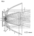
- Fig. 1 shows an illumination apparatus in a first embodiment of the present invention.
- Fig. 2 shows the illumination apparatus of Fig. 1 with a small-diameter reflecting mirror shifted forward.
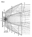
- Fig. 3 shows the illumination apparatus of Fig. 2 with a small-diameter reflecting mirror shifted further forward.
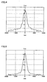
- Fig. 4 shows a light distribution pattern at a position 10 m ahead of the illumination apparatus of Fig. 1.
- Fig. 5 shows a light distribution pattern at a position 10 m ahead of the illumination apparatus of Fig. 2.
- Fig. 6 shows a light distribution pattern at a position 10 m ahead of the illumination apparatus of Fig. 3
- Fig. 7 shows a light distribution pattern at a position 10 m ahead of an illumination apparatus as a first comparative example.
- Fig. 8 shows a light distribution pattern at a position 10 m ahead of an illumination apparatus with a light-source shifted 5 mm in a lateral direction as a second comparative example.
- Fig. 9 shows a mechanism for moving the small-diameter reflecting mirror in the illumination apparatus in the first embodiment of the present invention.
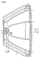
- Fig. 10 shows an illumination apparatus in a second embodiment of the present invention.
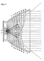
- Fig. 11 shows an illumination apparatus as a third comparative example.
- The embodiments of the present invention will now be described with reference to the figures.
- In Fig. 1, an
LED device 5 is provided with anLED chip 6 serving as a light source to allow a high-power light emission. This LED chip has a surface-emitting portion of 1.0 mm×1.0 mm, from which light is emitted. In front ofLED chip 6, a small-diameter reflecting mirror 2 having a tapered tubular shape is arranged at a position of a distance d1. A reflectingmirror 4 having an aperture larger than that of small-diameter reflecting mirror 2 is arranged to encloseLED chip 6 and small-diameter reflecting mirror 2. Unlike a filament, the LED chip does not emit light isotropically. In other words, it does not emit light backward but emits light in a range ahead of a plane including a substrate surface of the LED chip. Reflectingmirror 4 is a rotating parabolic mirror and has its focus arranged with the LED chip. - Light F1 emitted from
LED chip 6 at a small inclination angle with respect to the optical axis enters small-diameter reflecting mirror 2 and passes through the small-diameter reflecting mirror as it is without reaching the reflecting surface. Therefore, light F1 diverges widely, for example, at a position 10 m ahead. Light F2 emitted at an inclination angle larger than that of light F1 with respect to the optical axis is reflected on the reflecting surface of small-diameter reflecting mirror 2 and is projected forward at the inclination angle close to that of F1. - Light F3 emitted from
LED chip 6 at an inclination angle larger than that of light F2 passes outside the range of the small-diameter reflecting mirror and is reflected on the reflecting surface of reflectingmirror 4 to form parallel rays parallel to the optical axis to be projected forward. This part of light F3, serves as light illuminating the center region, for example, at a position 10 m ahead. - In the arrangement of Fig. 1 where the small-diameter reflecting mirror is proximate to the light source, the proportion of light F1 passing through the small-diameter reflecting mirror as it is and light F2 reflected at the small-diameter reflecting mirror is high. In addition, the light reflected at the small-diameter reflecting mirror is projected forward at a large inclination angle with respect to the optical axis. Therefore, in the arrangement of Fig. 1, light is distributed very widely. However, because of light F3 as described above, the illuminance at the center region can be sufficiently obtained, for example, at the position 10 m ahead.
- Fig. 2 illustrates a light distribution characteristic in the case where small-
diameter reflecting mirror 2 is arranged spaced apart fromLED chip 6 at a distance d2 greater than distance d1 in Fig. 1. As a matter of course, the separation of small-diameter reflecting mirror 2 fromlight source 6 can increase the amount of light F3 directed toward reflectingmirror 4. Therefore, the illuminance at the center region ahead can be increased. Furthermore, since the inclination angle with respect to the optical axis of the light reflected on the reflecting surface of the small-diameter reflecting mirror and then projected forward is small, the degree of divergence is reduced, thereby increasing the center intensity. - As the amount of light F1 passing through small-
diameter reflecting mirror 2 as it is decreases, the amount of diverging light decreases. However, this amount of light is not so large as to affect the illuminance at the center region to increase the illuminance at the center region ahead. - Fig. 3 illustrates a light distribution characteristic in the case where small-
diameter reflecting mirror 2 is arranged spaced apart fromLED chip 6 at a distance d3 greater than distance d2 in Fig. 2. In this case, the amount of light F3 reflected on the reflecting mirror increases, and therefore the proportion of the light parallel to the optical axis increases. Light F2 reflected at the small-diameter reflecting mirror is projected forward as parallel rays approximately parallel to the optical axis. The proportion of light F1 passing through the small-diameter reflecting mirror decreases. Therefore, the light distribution pattern, for example, at a position 10 m ahead is such that the illuminance at the center region is extremely high and the illuminance at the peripheral region is low. - Figs. 4-6 show light distribution patterns at a position 10 m ahead, which correspond to the arrangements of Figs. 1-3, respectively. Fig. 4 shows that light distribution extends corresponding to the light distribution pattern in which the illuminance is low at the center region and high at the periphery, as illustrated in Fig. 1. However, the peak at the center region is clear, approximately at 6 Lux. In other words, it can be understood that the illuminance at the center region can be kept at a certain level or higher even when the light distribution is expanded.
- Fig. 5 shows a light distribution pattern with distance d2 between
LED chip 6 and small-diameter reflecting mirror 2. The illuminance at the center region exceeds 12 Lux, and it can be understood that the illuminance at the center region is enhanced. Furthermore, the illuminance of about 1 Lux can be obtained even at a position approximately 1 m away from the center. - Fig. 6 shows a light distribution pattern at a position 10 m ahead, which corresponds to the arrangement of Fig. 3. As light F2 reflected at the small-diameter reflecting mirror is projected forward parallel to the optical axis, the illuminance at the center region is extremely high, reaching 100 Lux. Furthermore, the illuminance at a position 1 m away from the center is zero. It can be understood that the light is well focused to illuminate the central position ahead.
- By using two light distribution mechanisms of the reflecting mirror and the small-diameter reflecting mirror and by varying the distance between the light source and the small-diameter reflecting mirror, as described above, the light distribution can be spread out or narrowed with the illuminance at the center ahead being kept at a certain level or higher. In this case, as compared with the conventional example, high efficiency can be obtained, which will be described later.
- For comparison, a distribution pattern in the case where the small-diameter reflecting mirror as described above is not arranged, will be described. Fig. 7 shows a light distribution pattern at a position 10 m ahead where the small-diameter reflecting mirror is not arranged. In this case, the light reaching the reflecting mirror and being reflected on the reflecting mirror is projected forward as light rays parallel to the optical axis. As a result, the illuminance at the center region is as high as over 90 Lux. However, as compared with Fig. 6 showing the light distribution pattern where light is collected at the center region in the present embodiment, the peak value is slightly lower and the width is narrower. It can be understood that this example is clearly inferior in terms of the efficient use of light from the light source. By contrast, the illumination apparatus in the first embodiment of the present invention can have excellent efficiency as compared with the conventional example.
- Fig. 8 shows a light distribution pattern at a position 10 m ahead where the small-diameter reflecting mirror is not arranged and the LED chip is shifted 5 mm from the center in Fig. 1. In this arrangement, the light distribution range is expanded at the position 10 m ahead, thereby achieving the purpose of expanding illumination. However, the illuminance is extremely reduced at the center region, resulting in doughnut-shaped illumination. In the present embodiment, expansion of illumination does not result in doughnut-shaped illumination, and the illumination range can be expanded while the illuminance at the center region is assured.
- Fig. 9 shows a mechanism for moving the small-diameter reflecting mirror as shown in Figs. 1-3. In this illumination apparatus,
LED device 5 and reflectingmirror 4 are integrally formed, and a light source-fixing member 7 for fixingLED device 5 is integrated with the LED device. Therefore,LED device 5 includingLED chip 6, reflectingmirror 4 and light source-fixing member 7 are connected to each other for integration. - A transparent protective cover 1 positioned at the front of this illumination apparatus is connected and integrated with small-
diameter reflecting mirror 2. This protective cover is a forward projecting means-fixing member. The protective cover is screwed to light source-fixing member 7 with ascrew mechanism 3. Distance d betweenLED chip 6 and small-diameter reflecting mirror 2 can be adjusted by adjusting the length of the screw portion. More specifically, distance d betweenLED chip 6 and the small-diameter reflecting mirror is changed during the use of the illumination apparatus by turning protective cover 1 by one hand, in order to vary the illumination range ahead. - In doing so, irrespective of variations of distance d, the positional relationship between reflecting
mirror 4 andLED chip 6 serving as a light source is not changed. Therefore, with any variation of distance d, the illuminance at the center region ahead can be kept at a certain level or higher. On that condition, the degree of extension of forward light distribution from the center to the outside can be adjusted by varying distance d. - In addition, what is important is that two light distribution mechanisms are effectively used for the same light source to provide illumination with higher efficiency than the conventional example, as described above. This is because the light emitted from the light source is received by two light distribution mechanisms and then projected forward, so that the available quantity of light is increased as compared with the conventional example.
- Fig. 10 shows an illumination apparatus in a second embodiment of the present invention. In Fig. 10, a
Fresnel lens 8 that is a forward projecting means is arranged in front of the LED chip with a stepped surface 8e facing forward. The second embodiment differs from the first embodiment in that the small-diameter reflecting mirror is replaced withFresnel lens 8 as the forward projecting means and that a transparentprotective cover 9 is provided. The other parts are the same with the first embodiment. More specifically,LED chip 6 is positioned at the focus of a rotating parabolic mirror serving as a reflecting mirror, and the light reaching the reflecting mirror is projected forward as parallel rays parallel to the optical axis. -
Fresnel lens 8 functions similar to a convex lens. The LED chip is arranged at the focus of the Fresnel lens, so that the light reaching the Fresnel lens from the light source is projected forward as parallel rays parallel to the optical axis, thereby improving the illuminance at the center region ahead. Furthermore, the distance between the Fresnel lens and the LED chip is reduced as compared with the arrangement shown in Fig. 10, so that the light projected forward from the Fresnel lens is expanded, thereby increasing the illuminance in an extended region outside the center region ahead. - In Fig. 10, stepped
surface 8s of the Fresnel lens is faced forward on the opposite side of the light source, so that no light reaches exposedstep surface 8b directly from the light source and all the light beams reaching the Fresnel lens are effectively projected forward. By contrast, as shown in Fig. 11, when steppedsurface 8s is arranged at the light source side, lights F11, F12, F13 of the light from the light source directly radiate on exposedstep surface 8b. As described above, the exposed step surface is a surface that would not exist on a surface of a convex lens and is irrelevant withsurface 8a of the optical system. Therefore, lights F11, F12, F13 applied on the exposed step surface are ineffective light in which parallel rays are not projected forward. This is a major factor of efficiency reduction in projecting light forward using a Fresnel lens. - By arranging the stepped surface to face forward on the opposite side of the light source and by arranging transparent
protective cover 9 to prevent the stepped surface from being exposed to outside air, high efficiency can be assured and deposition of dusts and the like can be prevented. - In Fig. 10, lights F1, F3 reaching
Fresnel lens 8 and reflectingmirror 4 are both projected forward as rays parallel to the optical axis, so that illumination with a high illuminance can be formed at the center region ahead. Light F2 passing between reflectingmirror 4 andFresnel lens 8 diverges to contribute to the illumination in the nearby surrounding area. - Although the present invention has been described and illustrated in detail, it is clearly understood that the same is by way of illustration and example only and is not to be taken by way of limitation, the scope of the present invention being limited only by the terms of the appended claims.
Claims (6)
- An illumination apparatus projecting light forward, comprising:a light source (6);forward projecting means (2) positioned in front of said light source for receiving light from said light source to project the light forward; anda reflecting mirror (4) enclosing said light source (6) and said forward projecting means (2) for directing and reflecting forward the light from said light source, distance varying means (3) that can vary a distance between said forward projecting means and said light source characterized in that the light source is positioned fixedly relative to the reflecting mirror.
- The illumination apparatus according to claim 1, wherein said reflecting mirror (4) is a parabolic mirror, and said light source (6) is positioned at a focus of the parabolic mirror.
- The illumination apparatus according to claim 1 or 2, wherein said forward projecting means is a Fresnel lens (8) having a stepped surface arranged on a plane on opposite side of said light source,
the illumination apparatus further comprising transparent air-blocking mean (9) provided in front of said Fresnel lens to prevent said Fresnel lens from being exposed to air. - The illumination apparatus according to one of claims 1 or 2, wherein said forward projecting means (2) is a small-diameter reflecting mirror having an aperture smaller than that of said reflecting mirror.
- The illumination apparatus according to one of claims 1-4, wherein said distance varying means is a screw mechanism (3) provided between a light source-fixing member (7) fixing said light source and a forward projecting means-fixing member fixing said forward projecting means.
- The illumination apparatus according to one of claims 1 to 5, wherein said light source is an LED (Light Emitting Diode).
Applications Claiming Priority (2)
| Application Number | Priority Date | Filing Date | Title |
|---|---|---|---|
| JP2003047790A JP2004259541A (en) | 2003-02-25 | 2003-02-25 | Lighting fixture |
| JP2003047790 | 2003-02-25 |
Publications (3)
| Publication Number | Publication Date |
|---|---|
| EP1452797A1 EP1452797A1 (en) | 2004-09-01 |
| EP1452797B1 true EP1452797B1 (en) | 2006-01-11 |
| EP1452797B2 EP1452797B2 (en) | 2010-02-24 |
Family
ID=32767733
Family Applications (1)
| Application Number | Title | Priority Date | Filing Date |
|---|---|---|---|
| EP04004221A Expired - Fee Related EP1452797B2 (en) | 2003-02-25 | 2004-02-25 | Illumination apparatus |
Country Status (9)
| Country | Link |
|---|---|
| US (1) | US7207697B2 (en) |
| EP (1) | EP1452797B2 (en) |
| JP (1) | JP2004259541A (en) |
| CN (1) | CN1303356C (en) |
| CA (1) | CA2458727C (en) |
| DE (1) | DE602004000308T3 (en) |
| DK (1) | DK1452797T3 (en) |
| HK (1) | HK1067403A1 (en) |
| TW (1) | TWI297758B (en) |
Families Citing this family (69)
| Publication number | Priority date | Publication date | Assignee | Title |
|---|---|---|---|---|
| CN100370194C (en) * | 2003-10-31 | 2008-02-20 | 赵小峰 | Solar collecting and utilizing device |
| JP2005166371A (en) * | 2003-12-01 | 2005-06-23 | Ichikoh Ind Ltd | Lighting fixture for vehicle |
| DE10359185B4 (en) * | 2003-12-17 | 2012-05-31 | Hella Kgaa Hueck & Co. | Lamp for vehicles |
| WO2006032160A1 (en) | 2004-09-21 | 2006-03-30 | Volpi Ag | Illumination source |
| US10487999B2 (en) * | 2007-05-31 | 2019-11-26 | Tseng-Lu Chien | Multiple functions LED night light |
| US7125147B2 (en) * | 2004-11-18 | 2006-10-24 | Waring Patrick S | Method and apparatus for directing light from a light source |
| FR2889731B1 (en) * | 2005-08-11 | 2008-03-07 | Thorn Europhane Sa | LIGHTING DEVICE WITH VARIABLE OPENING OF THE LIGHT BEAM |
| US7914173B2 (en) * | 2005-11-17 | 2011-03-29 | Koninlijke Philips Electronics N.V. | Lamp assembly |
| JP4541290B2 (en) * | 2005-12-07 | 2010-09-08 | 株式会社小糸製作所 | Vehicle cornering lamp |
| JP2008016341A (en) * | 2006-07-06 | 2008-01-24 | Ri Bunsu | Led lighting device having high uniformity |
| JP4721445B2 (en) * | 2006-09-25 | 2011-07-13 | スタンレー電気株式会社 | Vehicle lighting |
| JP2008091143A (en) * | 2006-09-29 | 2008-04-17 | Seiko Epson Corp | Light source device and projector |
| CN101067479A (en) * | 2007-02-06 | 2007-11-07 | 宁波安迪光电科技有限公司 | Large power LED illuminating device |
| CN101730818A (en) * | 2007-05-07 | 2010-06-09 | 戴维·A·文豪斯 | Solid state optical system |
| US8317367B2 (en) * | 2007-05-07 | 2012-11-27 | Illumination Optics Inc. | Solid state optical system |
| JP5661455B2 (en) * | 2007-05-07 | 2015-01-28 | クリー インコーポレイテッドCree Inc. | Lighting apparatus and lighting device |
| US11114594B2 (en) | 2007-08-24 | 2021-09-07 | Creeled, Inc. | Light emitting device packages using light scattering particles of different size |
| JP5000464B2 (en) * | 2007-11-26 | 2012-08-15 | パナソニック株式会社 | Louver built-in projector |
| WO2009067843A1 (en) * | 2007-11-28 | 2009-06-04 | Tony Chunlung Young | Multi-reflector mechanism for a led light source |
| US20090135606A1 (en) * | 2007-11-28 | 2009-05-28 | Caltraco International Limited | Multi-reflector mechanism for a led light source |
| US8985814B2 (en) * | 2007-12-13 | 2015-03-24 | Valeo North America, Inc. | Dynamic three dimensional effect lamp assembly |
| CN101463970B (en) * | 2007-12-21 | 2011-01-19 | 海洋王照明科技股份有限公司 | Light modulation lamp and light modulation method |
| FI122909B (en) * | 2008-01-07 | 2012-08-31 | Naplit Show Oy | Lighting elements |
| WO2009114783A1 (en) | 2008-03-13 | 2009-09-17 | Fraen Corporation | Reflective variable spot size lighting devices and systems |
| US9287469B2 (en) | 2008-05-02 | 2016-03-15 | Cree, Inc. | Encapsulation for phosphor-converted white light emitting diode |
| JP2011523511A (en) | 2008-05-29 | 2011-08-11 | クリー インコーポレイテッド | Light source that mixes light in the near field |
| DE102008049532A1 (en) * | 2008-09-29 | 2010-04-01 | Volkswagen Ag | Headlight for motor vehicle, has reflectors arranged such that part of light emitted from light source meets and reflects on reflectors and other part of light is made available after reflection |
| CN102449378A (en) * | 2009-11-06 | 2012-05-09 | 松下电器产业株式会社 | Spot light source and bulb-type light source |
| FR2957134B1 (en) * | 2010-03-05 | 2015-08-21 | Valeo Vision | LIGHTING MODULE WITH TWO REFLECTORS OF DIFFERENT FOCAL DISTANCES |
| US8360605B2 (en) | 2010-05-09 | 2013-01-29 | Illumination Optics Inc. | LED luminaire |
| US8419231B2 (en) | 2010-07-09 | 2013-04-16 | Leroy E. Anderson | LED extended optic tir light cover with light beam control |
| CN102410496A (en) * | 2010-09-20 | 2012-04-11 | 刘克迅 | Light source condensation device and fixture thereof |
| DE102010048561A1 (en) * | 2010-10-18 | 2012-04-19 | ATMOS Medizin Technik GmbH & Co. KG | LED array with improved light output and method of operating an LED array with improved light output |
| JP5216113B2 (en) * | 2011-02-24 | 2013-06-19 | フェニックス電機株式会社 | Light emitting device |
| EP2511595B1 (en) * | 2011-04-15 | 2013-12-11 | Bega Gantenbrink-Leuchten KG | Headlamp with low half-peak divergence |
| US9234645B2 (en) * | 2011-07-06 | 2016-01-12 | Lg Innotek Co., Ltd. | Lighting device having adjustable reflector |
| JP2014525656A (en) * | 2011-09-06 | 2014-09-29 | コーニンクレッカ フィリップス エヌ ヴェ | Diagonal lighting fixture |
| EP2573452B1 (en) * | 2011-09-26 | 2016-12-28 | Max Lux Corp., Ltd. | An improved optical package and a torch having the optical package |
| CN103988110B (en) * | 2011-12-13 | 2018-09-28 | 飞利浦照明控股有限公司 | Optics collimator for LED light |
| RU2670177C2 (en) * | 2011-12-13 | 2018-10-18 | Филипс Лайтинг Холдинг Б.В. | Optical collimator for led lights |
| US8858036B2 (en) * | 2012-01-31 | 2014-10-14 | RAB Lighting Inc. | Compact concentric array reflector for LED light fixture |
| WO2013134369A1 (en) * | 2012-03-06 | 2013-09-12 | Fraen Corporation | Oscillating interface for light mixing lenses |
| DE202012003725U1 (en) * | 2012-03-28 | 2012-06-05 | Iventum Gmbh | lamp |
| KR101369722B1 (en) * | 2012-03-30 | 2014-03-06 | 케이엘전기(주) | Lighting device |
| JP6169829B2 (en) * | 2012-07-09 | 2017-07-26 | 交和電気産業株式会社 | Lighting device |
| RU2636754C2 (en) * | 2012-08-23 | 2017-11-28 | Филипс Лайтинг Холдинг Б.В. | Illuminator with led and improved reflective collimator |
| US8921813B2 (en) * | 2012-09-24 | 2014-12-30 | William Palmer | Reflector for ultraviolet sterilizer fixture |
| JP6351634B2 (en) * | 2013-02-19 | 2018-07-04 | フィリップス ライティング ホールディング ビー ヴィ | Apparatus including optical device and reflector |
| US8770800B1 (en) * | 2013-03-15 | 2014-07-08 | Xicato, Inc. | LED-based light source reflector with shell elements |
| EP2796778B1 (en) * | 2013-04-26 | 2017-02-01 | Hella KGaA Hueck & Co. | Lighting system |
| CN104214585A (en) * | 2013-05-29 | 2014-12-17 | 海洋王(东莞)照明科技有限公司 | Light projecting lamp with built-in grid |
| TW201508207A (en) * | 2013-08-27 | 2015-03-01 | Hon Hai Prec Ind Co Ltd | Vehicle lamp module |
| WO2015133196A1 (en) * | 2014-03-03 | 2015-09-11 | 株式会社アイ・ライティング・システム | Lighting device and led light source unit |
| US9279548B1 (en) * | 2014-08-18 | 2016-03-08 | 3M Innovative Properties Company | Light collimating assembly with dual horns |
| US9500324B2 (en) * | 2014-09-02 | 2016-11-22 | Ketra, Inc. | Color mixing optics for LED lighting |
| US10036535B2 (en) * | 2014-11-03 | 2018-07-31 | Ledvance Llc | Illumination device with adjustable curved reflector portions |
| WO2016104426A1 (en) * | 2014-12-25 | 2016-06-30 | 株式会社小糸製作所 | Lighting device |
| EP3282175B1 (en) * | 2015-04-10 | 2020-07-15 | Modulex Inc. | Sharpener and lighting fixture |
| CN105042406B (en) * | 2015-06-03 | 2017-08-08 | 潮州市西朗德光学科技有限公司 | A kind of LED beam condensing unit |
| KR102659369B1 (en) * | 2016-03-23 | 2024-04-22 | 쑤저우 레킨 세미컨덕터 컴퍼니 리미티드 | Optical module |
| JP6816413B2 (en) * | 2016-09-02 | 2021-01-20 | ウシオ電機株式会社 | Light irradiation device |
| US10337695B2 (en) * | 2016-10-26 | 2019-07-02 | JST Performance, LLC | Reflector for lighting component with surfaces that subtend light from a light source and surfaces that subtend external light |
| DE102016120743A1 (en) * | 2016-10-31 | 2018-05-03 | Biolitec Unternehmensbeteiligungs Ii Ag | lighting unit |
| CN106641903B (en) * | 2016-11-25 | 2023-03-31 | 横店集团得邦照明股份有限公司 | LED down lamp with rotating structure and implementation method thereof |
| US9719664B1 (en) * | 2017-01-24 | 2017-08-01 | Feniex Industries, Inc. | Vehicle illumination apparatus having adjustable modular optical units with reflectors |
| JP2019192471A (en) * | 2018-04-24 | 2019-10-31 | 株式会社小糸製作所 | Lighting fixture for vehicle |
| DE102020127476A1 (en) | 2020-10-19 | 2022-04-21 | Erco Gmbh | building light |
| US11402079B1 (en) * | 2020-10-29 | 2022-08-02 | Chien Luen Industries Co., Ltd., Inc. | Landscape lamps with adjustable light modifiers |
| US11655955B1 (en) * | 2022-08-05 | 2023-05-23 | Min Hsiang Corporation | Vehicle lamp structure |
Family Cites Families (25)
| Publication number | Priority date | Publication date | Assignee | Title |
|---|---|---|---|---|
| FR654983A (en) | 1927-05-31 | 1929-04-12 | Improvements to anti-shattering devices for automobile headlights | |
| DE535057C (en) | 1930-08-17 | 1931-10-06 | Francois Jacques Andre Darrass | Headlights for motor vehicles |
| FR998361A (en) | 1948-11-02 | 1952-01-17 | Philips Nv | Lighting fixture |
| US4530040A (en) * | 1984-03-08 | 1985-07-16 | Rayovac Corporation | Optical focusing system |
| DE8622788U1 (en) | 1986-08-26 | 1988-06-30 | Dedotec Optronische Und Mechanische Systeme Gmbh, 8000 Muenchen, De | |
| EP0380663A4 (en) | 1988-03-30 | 1990-10-24 | Nauchno-Proizvodstevennoe Obiedinenie Po Avtoelektronike I Avtotraktornomu Elektrooborudovaniju | Collimator |
| FR2657146A1 (en) | 1990-01-18 | 1991-07-19 | Dilouya Gilbert | Headlamp fitted with a flux mask/collector, especially for motor vehicles |
| US5138540A (en) * | 1990-04-24 | 1992-08-11 | Koito Manufacturing Co., Ltd. | Variable light distribution type headlamp |
| DE4016531A1 (en) | 1990-05-22 | 1991-11-28 | Trilux Lenze Gmbh & Co Kg | Recessed spotlight for ceiling mounting - has adjustable reflector provided in two parts respectively attached to lamp holder and base frame |
| US5749645A (en) * | 1990-07-16 | 1998-05-12 | Mag Instrument, Inc. | Flashlight |
| DE4023408A1 (en) * | 1990-07-23 | 1992-01-30 | Delma Elektro Med App | OPERATION LIGHT |
| JP2955140B2 (en) | 1992-12-08 | 1999-10-04 | スタンレー電気株式会社 | LED light source vehicle lighting |
| DE9315627U1 (en) | 1993-10-13 | 1994-09-29 | Wila Leuchten Gmbh | Luminaire with a height-adjustable secondary reflector device |
| US5490045A (en) * | 1994-09-29 | 1996-02-06 | Elgin Molded Plastics, Inc. | Barrier light with lens-coupled, self-orienting limited field light source |
| US5582479A (en) | 1995-03-01 | 1996-12-10 | Eppi Lighting, Inc. | Dual reflector high bay lighting system |
| DE19632189A1 (en) | 1996-08-09 | 1998-02-12 | Bosch Gmbh Robert | Vehicle headlamp |
| FR2767182B1 (en) | 1997-08-11 | 1999-09-03 | Valeo Vision | VARIABLE BEAM PROJECTOR, ESPECIALLY FOR VEHICLES |
| JPH11176221A (en) * | 1997-12-12 | 1999-07-02 | Moritex Corp | Light source device and axicon prism for use in it |
| CA2277502A1 (en) * | 1998-07-17 | 2000-01-17 | Donald D. Bartholomew | Quick connector |
| DE19832466A1 (en) | 1998-07-18 | 2000-02-17 | Volkswagen Ag | Projection type headlamp assembly for a motor vehicle |
| JP3390413B2 (en) | 2000-08-07 | 2003-03-24 | 株式会社キャットアイ | head lamp |
| JP3390412B2 (en) | 2000-08-07 | 2003-03-24 | 株式会社キャットアイ | head lamp |
| ATE370367T1 (en) | 2000-08-11 | 2007-09-15 | Brinkmann Corp | FLASHLIGHT WITH ONE LED |
| JP2002093209A (en) * | 2000-09-11 | 2002-03-29 | Koito Mfg Co Ltd | Vehicle lamp |
| ITTO20010464A1 (en) * | 2001-05-18 | 2002-11-18 | Fiat Ricerche | CONTROLLED LUMINANCE LIGHTING DEVICE. |
-
2003
- 2003-02-25 JP JP2003047790A patent/JP2004259541A/en active Pending
-
2004
- 2004-02-04 TW TW093102464A patent/TWI297758B/en not_active IP Right Cessation
- 2004-02-20 US US10/783,613 patent/US7207697B2/en not_active Expired - Fee Related
- 2004-02-25 DK DK04004221T patent/DK1452797T3/en active
- 2004-02-25 CA CA002458727A patent/CA2458727C/en not_active Expired - Fee Related
- 2004-02-25 CN CNB2004100082934A patent/CN1303356C/en not_active Expired - Fee Related
- 2004-02-25 EP EP04004221A patent/EP1452797B2/en not_active Expired - Fee Related
- 2004-02-25 DE DE602004000308T patent/DE602004000308T3/en not_active Expired - Lifetime
- 2004-12-28 HK HK04110281A patent/HK1067403A1/en not_active IP Right Cessation
Also Published As
| Publication number | Publication date |
|---|---|
| DK1452797T3 (en) | 2006-05-15 |
| US7207697B2 (en) | 2007-04-24 |
| US20040165388A1 (en) | 2004-08-26 |
| HK1067403A1 (en) | 2005-04-08 |
| JP2004259541A (en) | 2004-09-16 |
| TW200419101A (en) | 2004-10-01 |
| EP1452797A1 (en) | 2004-09-01 |
| DE602004000308D1 (en) | 2006-04-06 |
| CN1303356C (en) | 2007-03-07 |
| TWI297758B (en) | 2008-06-11 |
| DE602004000308T3 (en) | 2010-08-26 |
| CA2458727A1 (en) | 2004-08-25 |
| DE602004000308T2 (en) | 2006-08-10 |
| CN1525098A (en) | 2004-09-01 |
| CA2458727C (en) | 2007-12-04 |
| EP1452797B2 (en) | 2010-02-24 |
Similar Documents
| Publication | Publication Date | Title |
|---|---|---|
| EP1452797B1 (en) | Illumination apparatus | |
| US7165871B2 (en) | Lamp | |
| US9506615B2 (en) | Motor vehicle headlamp having a multi-function projection module | |
| US7850345B2 (en) | Optic for LEDs and other light sources | |
| KR100845487B1 (en) | Vehicular lamp | |
| US10414329B2 (en) | LED fog lamp | |
| KR101962298B1 (en) | Vehicle lighting unit | |
| KR101925849B1 (en) | Vehicle lighting unit | |
| JP2003317513A (en) | Light source unit | |
| JP2002050212A (en) | Headlamp | |
| US10605427B1 (en) | Light source module and illumination device comprising the same | |
| US7040792B2 (en) | Light-emitting diode module for a vehicle headlamp, and a vehicle headlamp | |
| JPH04284301A (en) | Projector | |
| US11242970B2 (en) | Vehicle lamp | |
| KR102099792B1 (en) | Head lamp for vehicles | |
| JP2013062147A (en) | Vehicle headlamp | |
| KR101693922B1 (en) | Laser optical system for head lamp | |
| US7052166B2 (en) | Light emitting diode optics | |
| KR101979571B1 (en) | Head lamp for vehicles | |
| KR101111032B1 (en) | a spot lighting device | |
| WO2023277071A1 (en) | Vehicle lamp | |
| KR102166854B1 (en) | Head lamp for vehicles | |
| KR102105325B1 (en) | Head lamp for vehicles | |
| KR20190062732A (en) | Lamp for vehicle | |
| KR20150070675A (en) | Head lamp for vehicles |
Legal Events
| Date | Code | Title | Description |
|---|---|---|---|
| PUAI | Public reference made under article 153(3) epc to a published international application that has entered the european phase |
Free format text: ORIGINAL CODE: 0009012 |
|
| 17P | Request for examination filed |
Effective date: 20040701 |
|
| AK | Designated contracting states |
Kind code of ref document: A1 Designated state(s): AT BE BG CH CY CZ DE DK EE ES FI FR GB GR HU IE IT LI LU MC NL PT RO SE SI SK TR |
|
| AX | Request for extension of the european patent |
Extension state: AL LT LV MK |
|
| 17Q | First examination report despatched |
Effective date: 20040810 |
|
| AKX | Designation fees paid |
Designated state(s): BE DE DK FR GB NL |
|
| GRAP | Despatch of communication of intention to grant a patent |
Free format text: ORIGINAL CODE: EPIDOSNIGR1 |
|
| GRAS | Grant fee paid |
Free format text: ORIGINAL CODE: EPIDOSNIGR3 |
|
| GRAA | (expected) grant |
Free format text: ORIGINAL CODE: 0009210 |
|
| AK | Designated contracting states |
Kind code of ref document: B1 Designated state(s): BE DE DK FR GB NL |
|
| REF | Corresponds to: |
Ref document number: 602004000308 Country of ref document: DE Date of ref document: 20060406 Kind code of ref document: P |
|
| REG | Reference to a national code |
Ref country code: DK Ref legal event code: T3 |
|
| ET | Fr: translation filed | ||
| PLBI | Opposition filed |
Free format text: ORIGINAL CODE: 0009260 |
|
| PLAX | Notice of opposition and request to file observation + time limit sent |
Free format text: ORIGINAL CODE: EPIDOSNOBS2 |
|
| 26 | Opposition filed |
Opponent name: SITECO BELEUCHTUNGSTECHNIK GMBH Effective date: 20061011 |
|
| NLR1 | Nl: opposition has been filed with the epo |
Opponent name: SITECO BELEUCHTUNGSTECHNIK GMBH |
|
| PLBB | Reply of patent proprietor to notice(s) of opposition received |
Free format text: ORIGINAL CODE: EPIDOSNOBS3 |
|
| PGFP | Annual fee paid to national office [announced via postgrant information from national office to epo] |
Ref country code: DK Payment date: 20080215 Year of fee payment: 5 |
|
| PGFP | Annual fee paid to national office [announced via postgrant information from national office to epo] |
Ref country code: GB Payment date: 20080220 Year of fee payment: 5 Ref country code: NL Payment date: 20080220 Year of fee payment: 5 |
|
| PGFP | Annual fee paid to national office [announced via postgrant information from national office to epo] |
Ref country code: FR Payment date: 20080208 Year of fee payment: 5 |
|
| PGFP | Annual fee paid to national office [announced via postgrant information from national office to epo] |
Ref country code: BE Payment date: 20080410 Year of fee payment: 5 |
|
| PLBP | Opposition withdrawn |
Free format text: ORIGINAL CODE: 0009264 |
|
| BERE | Be: lapsed |
Owner name: *CATEYE CO. LTD Effective date: 20090228 |
|
| REG | Reference to a national code |
Ref country code: DK Ref legal event code: EBP |
|
| GBPC | Gb: european patent ceased through non-payment of renewal fee |
Effective date: 20090225 |
|
| NLV4 | Nl: lapsed or anulled due to non-payment of the annual fee |
Effective date: 20090901 |
|
| REG | Reference to a national code |
Ref country code: FR Ref legal event code: ST Effective date: 20091030 |
|
| PG25 | Lapsed in a contracting state [announced via postgrant information from national office to epo] |
Ref country code: NL Free format text: LAPSE BECAUSE OF NON-PAYMENT OF DUE FEES Effective date: 20090901 |
|
| PUAH | Patent maintained in amended form |
Free format text: ORIGINAL CODE: 0009272 |
|
| STAA | Information on the status of an ep patent application or granted ep patent |
Free format text: STATUS: PATENT MAINTAINED AS AMENDED |
|
| 27A | Patent maintained in amended form |
Effective date: 20100224 |
|
| AK | Designated contracting states |
Kind code of ref document: B2 Designated state(s): BE DE DK FR GB NL |
|
| PG25 | Lapsed in a contracting state [announced via postgrant information from national office to epo] |
Ref country code: BE Free format text: LAPSE BECAUSE OF NON-PAYMENT OF DUE FEES Effective date: 20090228 |
|
| PG25 | Lapsed in a contracting state [announced via postgrant information from national office to epo] |
Ref country code: FR Free format text: LAPSE BECAUSE OF NON-PAYMENT OF DUE FEES Effective date: 20090302 Ref country code: GB Free format text: LAPSE BECAUSE OF NON-PAYMENT OF DUE FEES Effective date: 20090225 |
|
| PG25 | Lapsed in a contracting state [announced via postgrant information from national office to epo] |
Ref country code: DK Free format text: LAPSE BECAUSE OF NON-PAYMENT OF DUE FEES Effective date: 20090831 |
|
| PGFP | Annual fee paid to national office [announced via postgrant information from national office to epo] |
Ref country code: DE Payment date: 20120222 Year of fee payment: 9 |
|
| REG | Reference to a national code |
Ref country code: DE Ref legal event code: R119 Ref document number: 602004000308 Country of ref document: DE Effective date: 20130903 |
|
| PG25 | Lapsed in a contracting state [announced via postgrant information from national office to epo] |
Ref country code: DE Free format text: LAPSE BECAUSE OF NON-PAYMENT OF DUE FEES Effective date: 20130903 |