EP1433714A2 - Carton and a handle therefor - Google Patents
Carton and a handle therefor Download PDFInfo
- Publication number
- EP1433714A2 EP1433714A2 EP04007636A EP04007636A EP1433714A2 EP 1433714 A2 EP1433714 A2 EP 1433714A2 EP 04007636 A EP04007636 A EP 04007636A EP 04007636 A EP04007636 A EP 04007636A EP 1433714 A2 EP1433714 A2 EP 1433714A2
- Authority
- EP
- European Patent Office
- Prior art keywords
- carton
- handle
- panel
- line
- apertures
- Prior art date
- Legal status (The legal status is an assumption and is not a legal conclusion. Google has not performed a legal analysis and makes no representation as to the accuracy of the status listed.)
- Withdrawn
Links
Images
Classifications
-
- B—PERFORMING OPERATIONS; TRANSPORTING
- B65—CONVEYING; PACKING; STORING; HANDLING THIN OR FILAMENTARY MATERIAL
- B65D—CONTAINERS FOR STORAGE OR TRANSPORT OF ARTICLES OR MATERIALS, e.g. BAGS, BARRELS, BOTTLES, BOXES, CANS, CARTONS, CRATES, DRUMS, JARS, TANKS, HOPPERS, FORWARDING CONTAINERS; ACCESSORIES, CLOSURES, OR FITTINGS THEREFOR; PACKAGING ELEMENTS; PACKAGES
- B65D71/00—Bundles of articles held together by packaging elements for convenience of storage or transport, e.g. portable segregating carrier for plural receptacles such as beer cans or pop bottles; Bales of material
- B65D71/06—Packaging elements holding or encircling completely or almost completely the bundle of articles, e.g. wrappers
- B65D71/12—Packaging elements holding or encircling completely or almost completely the bundle of articles, e.g. wrappers the packaging elements, e.g. wrappers being formed by folding a single blank
- B65D71/14—Packaging elements holding or encircling completely or almost completely the bundle of articles, e.g. wrappers the packaging elements, e.g. wrappers being formed by folding a single blank having a tubular shape, e.g. tubular wrappers without end walls
- B65D71/28—Packaging elements holding or encircling completely or almost completely the bundle of articles, e.g. wrappers the packaging elements, e.g. wrappers being formed by folding a single blank having a tubular shape, e.g. tubular wrappers without end walls characterised by the handles
- B65D71/30—Packaging elements holding or encircling completely or almost completely the bundle of articles, e.g. wrappers the packaging elements, e.g. wrappers being formed by folding a single blank having a tubular shape, e.g. tubular wrappers without end walls characterised by the handles unitary, i.e. integral with the tubular packaging elements
-
- B—PERFORMING OPERATIONS; TRANSPORTING
- B65—CONVEYING; PACKING; STORING; HANDLING THIN OR FILAMENTARY MATERIAL
- B65D—CONTAINERS FOR STORAGE OR TRANSPORT OF ARTICLES OR MATERIALS, e.g. BAGS, BARRELS, BOTTLES, BOXES, CANS, CARTONS, CRATES, DRUMS, JARS, TANKS, HOPPERS, FORWARDING CONTAINERS; ACCESSORIES, CLOSURES, OR FITTINGS THEREFOR; PACKAGING ELEMENTS; PACKAGES
- B65D71/00—Bundles of articles held together by packaging elements for convenience of storage or transport, e.g. portable segregating carrier for plural receptacles such as beer cans or pop bottles; Bales of material
- B65D71/06—Packaging elements holding or encircling completely or almost completely the bundle of articles, e.g. wrappers
- B65D71/12—Packaging elements holding or encircling completely or almost completely the bundle of articles, e.g. wrappers the packaging elements, e.g. wrappers being formed by folding a single blank
- B65D71/36—Packaging elements holding or encircling completely or almost completely the bundle of articles, e.g. wrappers the packaging elements, e.g. wrappers being formed by folding a single blank having a tubular shape, e.g. tubular wrappers, with end walls
-
- B—PERFORMING OPERATIONS; TRANSPORTING
- B65—CONVEYING; PACKING; STORING; HANDLING THIN OR FILAMENTARY MATERIAL
- B65D—CONTAINERS FOR STORAGE OR TRANSPORT OF ARTICLES OR MATERIALS, e.g. BAGS, BARRELS, BOTTLES, BOXES, CANS, CARTONS, CRATES, DRUMS, JARS, TANKS, HOPPERS, FORWARDING CONTAINERS; ACCESSORIES, CLOSURES, OR FITTINGS THEREFOR; PACKAGING ELEMENTS; PACKAGES
- B65D2571/00—Bundles of articles held together by packaging elements for convenience of storage or transport, e.g. portable segregating carrier for plural receptacles such as beer cans, pop bottles; Bales of material
- B65D2571/00123—Bundling wrappers or trays
- B65D2571/00432—Handles or suspending means
- B65D2571/00493—Handles or suspending means attached to the wrapper
-
- B—PERFORMING OPERATIONS; TRANSPORTING
- B65—CONVEYING; PACKING; STORING; HANDLING THIN OR FILAMENTARY MATERIAL
- B65D—CONTAINERS FOR STORAGE OR TRANSPORT OF ARTICLES OR MATERIALS, e.g. BAGS, BARRELS, BOTTLES, BOXES, CANS, CARTONS, CRATES, DRUMS, JARS, TANKS, HOPPERS, FORWARDING CONTAINERS; ACCESSORIES, CLOSURES, OR FITTINGS THEREFOR; PACKAGING ELEMENTS; PACKAGES
- B65D2571/00—Bundles of articles held together by packaging elements for convenience of storage or transport, e.g. portable segregating carrier for plural receptacles such as beer cans, pop bottles; Bales of material
- B65D2571/00123—Bundling wrappers or trays
- B65D2571/00432—Handles or suspending means
- B65D2571/00537—Handles or suspending means with stress relieving means
-
- B—PERFORMING OPERATIONS; TRANSPORTING
- B65—CONVEYING; PACKING; STORING; HANDLING THIN OR FILAMENTARY MATERIAL
- B65D—CONTAINERS FOR STORAGE OR TRANSPORT OF ARTICLES OR MATERIALS, e.g. BAGS, BARRELS, BOTTLES, BOXES, CANS, CARTONS, CRATES, DRUMS, JARS, TANKS, HOPPERS, FORWARDING CONTAINERS; ACCESSORIES, CLOSURES, OR FITTINGS THEREFOR; PACKAGING ELEMENTS; PACKAGES
- B65D2571/00—Bundles of articles held together by packaging elements for convenience of storage or transport, e.g. portable segregating carrier for plural receptacles such as beer cans, pop bottles; Bales of material
- B65D2571/00123—Bundling wrappers or trays
- B65D2571/00648—Elements used to form the wrapper
- B65D2571/00654—Blanks
- B65D2571/0066—Blanks formed from one single sheet
-
- B—PERFORMING OPERATIONS; TRANSPORTING
- B65—CONVEYING; PACKING; STORING; HANDLING THIN OR FILAMENTARY MATERIAL
- B65D—CONTAINERS FOR STORAGE OR TRANSPORT OF ARTICLES OR MATERIALS, e.g. BAGS, BARRELS, BOTTLES, BOXES, CANS, CARTONS, CRATES, DRUMS, JARS, TANKS, HOPPERS, FORWARDING CONTAINERS; ACCESSORIES, CLOSURES, OR FITTINGS THEREFOR; PACKAGING ELEMENTS; PACKAGES
- B65D2571/00—Bundles of articles held together by packaging elements for convenience of storage or transport, e.g. portable segregating carrier for plural receptacles such as beer cans, pop bottles; Bales of material
- B65D2571/00123—Bundling wrappers or trays
- B65D2571/00709—Shape of the formed wrapper, i.e. shape of each formed element if the wrapper is made from more than one element
- B65D2571/00722—Shape of the formed wrapper, i.e. shape of each formed element if the wrapper is made from more than one element tubular with end walls, e.g. walls not extending on the whole end surface
Definitions
- the present invention relates generally to paperboard carton blanks for use in packaging articles. It is particularly useful for cartons for packaging containers, for example cans or bottles for beverages, although the invention is not limited in this regard. More particularly, the invention relates to a handle for such cartons.
- Containers for example cans or bottles for beverages including soft drink, beer, juices and the like are commonly sold in multiple quantities packaged in a paperboard carton.
- the carton is often provided with a handle, which quite commonly includes as a primary feature one or two slots or other apertures formed in the carton. These slots are commonly formed into a top wall of the carton. The user inserts the hand or fingers into one or both of the slots to lift the carton. Many varieties of handles of this type are known in the art.
- the present invention and its preferred embodiment seeks to overcome or at least mitigate the problems of the prior art.
- One aspect of the invention provides a carton for packaging a plurality of articles, for example bottles comprising a plurality of panels for forming a tubular structure including a top wall panel having opposed side edges and end edges.
- the top wall panel is provided with a handle.
- a score line extends from the handle to a cut line disposed along a side edge of the top wall panel thereby to direct lifting stresses away from the handle.
- the handle may comprise first and second spaced apertures defining a handle panel.
- this aspect of the invention there may further comprises a second score line extending from an edge of the first hand aperture to the cut line and spaced from the first fold line to define a part of the top wall that is capable of flexing relative the top wall, thereby to direct the lifting stresses away from the handle and/or absorb said lifting stresses.
- a second aspect of the invention provides a blank for forming a carton for packaging a plurality of articles, for example bottles comprising a first side wall panel, a top wall panel having opposed side edges and end edges, a second side wall panel and a base panel hingedly connected together in series, wherein the top panel having first and second spaced apertures provided therein so as to define a handle panel wherein a score line extends from the handle to a cut line disposed along a side edge of the top wall panel.
- the score line may terminate intermediate the ends of the side edge cut line.
- the score line may diverge away from a linear path so as to intersect with the side edge cut line.
- At least one frangible line may extend from the first aperture to detachably connect the handle to the top wall panel and wherein the or each score line extends from a first frangible line.
- each/or frangible line may curve inwardly before terminating.
- the second score line may extend from a location on the aperture cut line proximate the intersection of the aperture with the frangible line.
- the second score line may extend from an edge of the aperture.
- one side of the handle there may comprise opposed frangible lines extending from the bandle and a second flexing part, wherein the second flexing part is defined by a third score line extending from the second frangible line to a second side edge cut line provided on the side edge, and a fourth score line extending from the aperture edge to an end of the second side edge cut line.
- the second and the fourth score lines may be arranged to be co-extensive.
- the other side of the handle may comprises opposed frangible lines extending from the handle and a pair of flexing parts extending between the handle and hand aperture and a pair of spaced cut lines struck from at he opposed side edge, wherein the pair of cut lines and the first and second cut lines are located in different relative longitudinal positions on the opposed side edges.
- the or each side edge cut line may form part of article receiving structure comprising opposed hingable flaps separated by a further cut line extending substantially perpendicular to the side edge cut line.
- a third aspect of the invention provides a handle structure for a carton for packaging a plurality of articles, for example bottles comprising a top wall panel having opposed side edges and end edges the top panel having first and second spaced apertures provided therein so as to define a handle.
- a score line extends from the handle to a cut line disposed along a side edge of the top wall panel and a second score line extending from an edge of the first hand aperture to the cut line and spaced from the first fold line to define a part of the top wall that is capable of flexing relative the top wall, thereby to direct the lifting stresses away from the handle and/or absorb said lifting stresses.
- a fourth aspect of the invention provides a carton for packaging four or more rows of articles for example bottles, which carton comprises a plurality of panels for forming a tubular structure including opposed first and second side wall panels, wherein the first and second side wall panels each comprising a pair of apertures to receive and retain a part of an article, characterised in that the first and second apertures of the first side wall engage an outermost article from a first row and a second row and in that third and fourth apertures of the second side wall panel engage an outermost article from a third row and fourth row.
- the first row may be adjacent the second row so that the first and second apertures are adjacent each other.
- the third and fourth rows may be separated by the first and second rows.
- the first and second apertures may be provided for the two centrally located articles in adjacent rows while the third and fourth apertures are provided for two off-centre bottles in the adjacent row.
- each aperture may be defined by one or more side opening flaps hingedly connected to the first or second side wall panels and adapted to articulate outwardly by an article present in the aperture.
- a blank 10 for forming a carton formed from paperboard or other suitable foldable sheet material comprises a plurality of panels for forming a tubular structure: in this embodiment there comprises a base wall panel 12, a side wall panel 14, a top wall panel 18 and a second side wall panel 20 hingedly connected together along fold lines 26, 28 and 30 respectively.
- the side wall panels 14 and 20 are arranged into upper parts 16, 21 and lower parts 15, 22.
- the upper part 16 is hingedly connected to the lower part 15 of side wall 14 along fold line 34.
- upper part 21 is hingedly connected to lower part 22 along fold line 36.
- end walls are provided at the opposing ends of the tubular structure and, on one side of the tubular structure there comprises upper and lower end wall panels 40, 42 hingedly connected to top wall panel 18 and base wall panel 12 respectively along to fold lines 46 and 44.
- Each gusset panel structure 50 is substantially the same and so only one such structure 50 will now be described in further detail below.
- the gusset panel structure 50 comprises lower gusset panel 52 hingedly connected to lower side wall panel 22 along fold line 58 and intermediate gusset panel 54 hingedly connected to upper side panel 21 along fold line 60.
- a connecting portion 64 connects gusset panels 52 and 54, but they are otherwise separated from each other by an aperture.
- fold line 62 is preferably configured to converge at the intersection of fold lines 30 and 60.
- a handle is provided in the top wall panel 18 which in one class of embodiments includes a pair of hand apertures 68 and 70 positioned either side of a handle panel 66.
- the apertures are generally oval in shape to receive a user's hand, although other shapes could be employed according to user requirements.
- the handle panel 66 is frangibly connected to top panel 18 along frangible lines 80 along a portion of each side edge but is otherwise separated from the top wall by the hand apertures 68, 70.
- the frangible lines 80 preferably curve inwardly before terminating.
- the handle panel 66 is elongate, although it is envisaged that the handle shape could be altered to the preferred user requirement.
- stress relief cut lines 79 which curve back outwardly through substantially 180°.
- a reinforcing strap "S" secured to opposing upper end wall panels 40 and 40a and the strip is also secured to the handle panel 66 by glue or other suitable means known in the art.
- a similar cushion flap 74 may be provided, which is connected to opposing side edge of handle panel 66 along fold line 78. It will be recognised that in the completed carton fold lines 76 and 78 will, preferably, lie substantially on the side edges of the underlying reinforcing strap "S".
- a plurality of article receiving arrangements 81, 81a are optionally provided for receiving and/or engaging an article which arrangements 81, 81a are struck from the upper side panels 16 and 21 respectively.
- the article receiving arrangements 81, 81a are substantially the same and only one arrangement shall therefore be described in any greater detail.
- the article receiving arrangement 81 comprises a pair of article receiving panels 82 and 84 struck from upper side wall panel 16 and hingedly connected thereto along divergent fold lines 86 and 88 respectively.
- the panels 82 and 84 may be substantially triangular in shape and are separated from the blank by a pair of cut lines 87, 89 to allow the panels 82, 84 to articulate about the fold lines 86, 88 to define a retaining aperture.
- One of the cut lines 89 preferably overlies fold line 28 and terminates with curved portions to provide some stress relief.
- cut line 89, 89a may be provided along one or more edges of the top wall.
- Each article receiving arrangement 81, 81a is configured to receive an outermost article from one of the rows as shown in Figures 2 and 4, whereby panels 82, 84 are folded in an outward direction by abutment with an upper part of the article received in the resulting retaining aperture.
- the configuration is for the article receiving arrangements 81a on one side of the top wall 18 to receive two adjacent articles A1, A2, for example third and fourth row and for the article receiving arrangements 81 on the other upper side wall to receive articles from different rows A3, A4 for example second and fifth rows in Figure 2.
- a plurality of stress-diverting score lines are formed in the top wall panel 18.
- a score line 90 extending from the handle panel 66 and terminating along the cut line 89a forming one of the article receiving arrangements 81a; preferably, intermediate the ends of the cut line 89a.
- score line 90 preferably comprises two straight portions angled obtusely to each other.
- there further comprises a pair of score lines 92, 94 which extend from the ends of cut lines 89a and converge at a point adjacent a central portion of aperture 70 and terminate at the outer edge thereof.
- the opposing side of the top panel further comprises a plurality of stress diverting score lines, however, as the article receiving arrangements are spaced further apart, the score lines are configured differently.
- Score line 100 extends from the end of handle panel 66 and terminates at cut line 89 of aperture receiving arrangement 81.
- Score line 100 preferably comprises two straight portions with an obtuse angle therebetween such that the score line 100 intersects the cut line 89 of one of the article receiving apertures 81 substantially perpendicular thereto.
- a second score line 98 preferably extends from fold line 88 to terminate at an outer edge of aperture 68.
- a second pair of score lines 99, 101 connects the other article receiving arrangement 81 with the handle panel 66 and aperture 68 respectively.
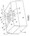
- each pair of adjacent score lines should be shaped to define a part 102, 104, 106, 108 of the top wall panel 18 shown in Figures 3 and 4 that can flex and/or bow relative the top and/or side walls of the carton, thereby to transmit, direct and/or absorb lifting stresses from the handle.
- the carton of the present invention can be formed by a series of sequential folding and gluing operations which can be performed in a straight line machine so that the carton is not required to be rotated or inverted to complete its construction.
- the folding process is not limited to that described below and can be altered according to particular manufacturing requirements.
- the carton can be seen in a tubular state formed from the blank 10.
- the handle reinforcing strap S is secured to the carton and the securing flap 24 is secured to base panel 12 by glue or other suitable means known in the art.
- the carton C is shown with its end closure structure, comprising upper end wall panels 40 and 40a and lower end wall panels 42 and 42a, open so that the carton is loaded from one or both ends with articles "A", as shown here for example, with beverage bottles arranged into a single tier.
- Articles "A" are positioned on the bottom wall panel 12 of the carton 10.
- Such a loading operation may be carried out by suitable, commercially-available automated packaging machinery.
- Closure of the end closure structure is preferably effected in the following manner.
- Upper end wall panels 40 is folded to a closed position against the packaged articles A, by folding gusset panel structures 50 inwardly.
- Glue is applied to lower end wall panel 42 and lower end wall panel 42 is then folded upwardly and secured to the upper end wall panel 40.
- the handle arrangement formed in top wall panel 18 may be seen in greater detail by reference to Figure 4.
- a user inserts the hand and/or fingers into one or both of the apertures 68 and 70 and grasps the portion of panel 66 therebetween.
- the user then lifts the carton C.
- the weight of the carton causes the lifting to separate the handle panel 66 from the top wall panel along the frangible lines 80 and thereafter to deflect the tearing stress along score lines 90, 92, 94, 96, 98, 100 toward the article receiving arrangements 81.
- those parts 102, 104, 106, 108 of the top wall between the above mentioned fold lines are allowed to flex and/or bow.
- each article receiving arrangement In the specific embodiment disclosed, a specific location for each article receiving arrangement is shown. However, the receiving arrangements may be located adjacent other articles within the article grouping, and the position of the score lines changed accordingly, within the scope of the invention.
- the frangible lines may tear to allow the handle panel 66 to protrude above the top wall panel 18.
- the curved stress relief lines 79 also assist in preventing the tearing from extending beyond frangible line 80. Because tearing in the top panel is controlled, overall tear-resistance is in fact improved. Not only is the handle of improved strength, but it also provides a comfortable "feel" for the user while lifting and/or carrying the carton.
- the handle structure may also be used with a carton for packaging two tiers of bottles, or for a carton for packaging cans, jars or other containers or articles.
- the containers may be oriented vertically, as described herein, or horizontally.
- handle reinforcing means other than that described herein may be used with the disclosed handle.
- a lapped top panel of a type generally known in the art may be used.
- the overlap between the two top panel portions forms a double-ply strip which extends down the centre of the carton top wall.
- An example of a carton of this type may be seen in U.S. Patent No. 5,427,242, which is incorporated herein by reference.
- the handle structure is formed into the lapped top panel in the same manner as the handle structure described herein, as will be readily appreciated by those skilled in the art.
- the frangible lines 80 are formed to extend along the edges of the lapped portion.
- hinged connection should not be construed as referring to a single fold line, indeed it is envisaged that a hinged connection can be formed from, a score line, a frangible line, or one, two or more fold lines without departing from the scope of invention.
Landscapes
- Engineering & Computer Science (AREA)
- Mechanical Engineering (AREA)
- Cartons (AREA)
- Packages (AREA)
- Wrapping Of Specific Fragile Articles (AREA)
- Details Of Rigid Or Semi-Rigid Containers (AREA)
Abstract
Description
- The present invention relates generally to paperboard carton blanks for use in packaging articles. It is particularly useful for cartons for packaging containers, for example cans or bottles for beverages, although the invention is not limited in this regard. More particularly, the invention relates to a handle for such cartons.
- Containers, for example cans or bottles for beverages including soft drink, beer, juices and the like are commonly sold in multiple quantities packaged in a paperboard carton. For the convenience of the consumer, the carton is often provided with a handle, which quite commonly includes as a primary feature one or two slots or other apertures formed in the carton. These slots are commonly formed into a top wall of the carton. The user inserts the hand or fingers into one or both of the slots to lift the carton. Many varieties of handles of this type are known in the art.
- Lifting a carton containing beverage cans or bottles introduces considerable stress into the paperboard from which the carton is formed. For this reason, and to prevent tearing of the paperboard and failure of the carton, a large number of carton handles have been devised over the years which include various reinforcement structures, aperture arrangements and locations, stress-directing fold lines, stress-relieving slits and the like.
- Recently, attempts have been made to introduce into the marketplace beverage cartons wherein cans are arranged in two tiers, with corresponding cans from each tier being axially aligned. An example of such a carton can be seen by reference to U.S. patent number 5,427,242. Such cartons are intended to hold relatively large numbers of cans, for example 24 to 36 cans. The contained weight of these cartons makes use of reinforced handle structures particularly advantageous.
- Moreover, despite the many handle designs which have been previously developed, there is always a need for handles with improved performance. A stronger handle may permit the use of larger cartons for packaging heavier loads, as well as the possibility of a smaller blank or lighter paperboard material. In view of the large numbers of cartons which are produced, the cost savings which can be realised from these latter advantages can be significant.
- The present invention and its preferred embodiment seeks to overcome or at least mitigate the problems of the prior art.
- One aspect of the invention provides a carton for packaging a plurality of articles, for example bottles comprising a plurality of panels for forming a tubular structure including a top wall panel having opposed side edges and end edges. The top wall panel is provided with a handle. A score line extends from the handle to a cut line disposed along a side edge of the top wall panel thereby to direct lifting stresses away from the handle.
- According to an optional feature of this aspect of the invention the handle may comprise first and second spaced apertures defining a handle panel.
- According to another optional feature of this aspect of the invention there may further comprises a second score line extending from an edge of the first hand aperture to the cut line and spaced from the first fold line to define a part of the top wall that is capable of flexing relative the top wall, thereby to direct the lifting stresses away from the handle and/or absorb said lifting stresses.
- A second aspect of the invention provides a blank for forming a carton for packaging a plurality of articles, for example bottles comprising a first side wall panel, a top wall panel having opposed side edges and end edges, a second side wall panel and a base panel hingedly connected together in series, wherein the top panel having first and second spaced apertures provided therein so as to define a handle panel wherein a score line extends from the handle to a cut line disposed along a side edge of the top wall panel.
- According to an optional feature of either aspect of the invention, the score line may terminate intermediate the ends of the side edge cut line. Optionally, the score line may diverge away from a linear path so as to intersect with the side edge cut line.
- According to an optional feature of the second aspect of the invention, there may further comprises a second score line extending from an edge of the first hand aperture to the cut line and spaced from the first fold line to define a part of the top wall panel that is capable of being moved out of the plane of the top wall in use.
- According to another optional feature of either aspect of the invention, at least one frangible line may extend from the first aperture to detachably connect the handle to the top wall panel and wherein the or each score line extends from a first frangible line.
- Optionally, each/or frangible line may curve inwardly before terminating.
- According to a further optional feature of either aspect of the invention, the second score line may extend from a location on the aperture cut line proximate the intersection of the aperture with the frangible line. Alternatively, the second score line may extend from an edge of the aperture.
- According to yet another optional feature of either aspect of the invention, on one side of the handle, there may comprise opposed frangible lines extending from the bandle and a second flexing part, wherein the second flexing part is defined by a third score line extending from the second frangible line to a second side edge cut line provided on the side edge, and a fourth score line extending from the aperture edge to an end of the second side edge cut line. Preferably, a portion of each of the second and the fourth score lines may be arranged to be co-extensive.
- More preferably, the other side of the handle may comprises opposed frangible lines extending from the handle and a pair of flexing parts extending between the handle and hand aperture and a pair of spaced cut lines struck from at he opposed side edge, wherein the pair of cut lines and the first and second cut lines are located in different relative longitudinal positions on the opposed side edges.
- According to a still further optional feature of this aspect of the invention, the or each side edge cut line may form part of article receiving structure comprising opposed hingable flaps separated by a further cut line extending substantially perpendicular to the side edge cut line.
- A third aspect of the invention provides a handle structure for a carton for packaging a plurality of articles, for example bottles comprising a top wall panel having opposed side edges and end edges the top panel having first and second spaced apertures provided therein so as to define a handle. A score line extends from the handle to a cut line disposed along a side edge of the top wall panel and a second score line extending from an edge of the first hand aperture to the cut line and spaced from the first fold line to define a part of the top wall that is capable of flexing relative the top wall, thereby to direct the lifting stresses away from the handle and/or absorb said lifting stresses.
- A fourth aspect of the invention provides a carton for packaging four or more rows of articles for example bottles, which carton comprises a plurality of panels for forming a tubular structure including opposed first and second side wall panels, wherein the first and second side wall panels each comprising a pair of apertures to receive and retain a part of an article, characterised in that the first and second apertures of the first side wall engage an outermost article from a first row and a second row and in that third and fourth apertures of the second side wall panel engage an outermost article from a third row and fourth row.
- Optionally, the first row may be adjacent the second row so that the first and second apertures are adjacent each other. Preferably, the third and fourth rows may be separated by the first and second rows. Alternatively, the first and second apertures may be provided for the two centrally located articles in adjacent rows while the third and fourth apertures are provided for two off-centre bottles in the adjacent row.
- According to an optional feature of the fourth aspect of the invention each aperture may be defined by one or more side opening flaps hingedly connected to the first or second side wall panels and adapted to articulate outwardly by an article present in the aperture.
- Exemplary embodiments will now be described, by way of example only, with reference to the accompanying drawings in which:-
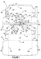
- FIGURE 1 is a plan view of the inner surface of a blank for forming a carton having a handle arrangement according to one aspect of the present invention;
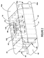
- FIGURE 2 is a perspective view showing a first step in the formation of a carton from the blank of Figure 1;
- FIGURE 3 shows the end closure structure sealed to form the completed carton; and
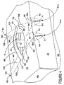
- FIGURE 4 shows an enlarged view of the top panel portion of the carton shown in Figure 3.
-
- Referring to the drawings, and in particular to Figure 1, there is shown a blank 10 for forming a carton formed from paperboard or other suitable foldable sheet material. The blank 10 comprises a plurality of panels for forming a tubular structure: in this embodiment there comprises a
base wall panel 12, aside wall panel 14, atop wall panel 18 and a secondside wall panel 20 hingedly connected together alongfold lines side wall panels upper parts lower parts upper part 16 is hingedly connected to thelower part 15 ofside wall 14 alongfold line 34. Likewise,upper part 21 is hingedly connected tolower part 22 alongfold line 36. There may further comprise securingflap 24 hingedly connected toside wall panel 20 alongfold line 32. - Optionally, end walls are provided at the opposing ends of the tubular structure and, on one side of the tubular structure there comprises upper and lower
end wall panels top wall panel 18 andbase wall panel 12 respectively along tofold lines gusset panel structures 50, to assist in forming one or both of the end walls. Eachgusset panel structure 50, is substantially the same and so only onesuch structure 50 will now be described in further detail below. - The
gusset panel structure 50 compriseslower gusset panel 52 hingedly connected to lowerside wall panel 22 alongfold line 58 andintermediate gusset panel 54 hingedly connected toupper side panel 21 alongfold line 60. A connectingportion 64 connectsgusset panels end wall panel 40 andintermediate gusset panel 54 alongfold line 62 and an extension offold line 30 respectively. To assist in folding,fold line 62 is preferably configured to converge at the intersection offold lines - It will be apparent from Figure 1 that the opposing end wall structure is substantially the same as that described above and therefore like reference numerals are employed with the addition of the letter "a".
- Turning to the handle structure, a handle is provided in the
top wall panel 18 which in one class of embodiments includes a pair ofhand apertures handle panel 66. The apertures are generally oval in shape to receive a user's hand, although other shapes could be employed according to user requirements. - Preferably the
handle panel 66 is frangibly connected totop panel 18 alongfrangible lines 80 along a portion of each side edge but is otherwise separated from the top wall by thehand apertures frangible lines 80 preferably curve inwardly before terminating. In this embodiment, thehandle panel 66 is elongate, although it is envisaged that the handle shape could be altered to the preferred user requirement. At the location in which thefrangible lines 80 deviate from their straight path, there are preferably provided stressrelief cut lines 79 which curve back outwardly through substantially 180°. - There may further comprise a reinforcing strap "S" secured to opposing upper
end wall panels handle panel 66 by glue or other suitable means known in the art. There may further comprise acushion flap 72 disposed along the inner side edge ofaperture 68 and connected to thehandle panel 66 by fold line 76. Asimilar cushion flap 74 may be provided, which is connected to opposing side edge ofhandle panel 66 along fold line 78. It will be recognised that in the completed carton fold lines 76 and 78 will, preferably, lie substantially on the side edges of the underlying reinforcing strap "S". - A plurality of
article receiving arrangements arrangements upper side panels article receiving arrangements article receiving arrangement 81 comprises a pair ofarticle receiving panels side wall panel 16 and hingedly connected thereto alongdivergent fold lines panels cut lines panels line 28 and terminates with curved portions to provide some stress relief. - In other embodiments, no article receiving arrangements are provided, although to assist in dissipating the stresses from the handle, cut
line - Each
article receiving arrangement panels article receiving arrangements 81a on one side of thetop wall 18 to receive two adjacent articles A1, A2, for example third and fourth row and for thearticle receiving arrangements 81 on the other upper side wall to receive articles from different rows A3, A4 for example second and fifth rows in Figure 2. - A plurality of stress-diverting score lines are formed in the
top wall panel 18. On one side of the carton with thearticle receiving arrangements 81a in adjacent positions, there comprises ascore line 90 extending from thehandle panel 66 and terminating along thecut line 89a forming one of thearticle receiving arrangements 81a; preferably, intermediate the ends of thecut line 89a. In this embodiment,score line 90 preferably comprises two straight portions angled obtusely to each other. There may further comprise asecond score line 96 extending from the opposing end ofhandle panel 66 and terminating at thecut line 89a following an edge of the otherarticle receiving arrangement 81a formed from theupper side panel 21. In this embodiment, there further comprises a pair ofscore lines cut lines 89a and converge at a point adjacent a central portion ofaperture 70 and terminate at the outer edge thereof. - The opposing side of the top panel further comprises a plurality of stress diverting score lines, however, as the article receiving arrangements are spaced further apart, the score lines are configured differently.
Score line 100 extends from the end ofhandle panel 66 and terminates atcut line 89 ofaperture receiving arrangement 81.Score line 100 preferably comprises two straight portions with an obtuse angle therebetween such that thescore line 100 intersects thecut line 89 of one of thearticle receiving apertures 81 substantially perpendicular thereto. Asecond score line 98 preferably extends fromfold line 88 to terminate at an outer edge ofaperture 68. Similarly, a second pair ofscore lines article receiving arrangement 81 with thehandle panel 66 andaperture 68 respectively. - The shape and configuration of the score lines is not limited to that described above and it is envisaged that other arrangements could be employed. However, each pair of adjacent score lines should be shaped to define a
part top wall panel 18 shown in Figures 3 and 4 that can flex and/or bow relative the top and/or side walls of the carton, thereby to transmit, direct and/or absorb lifting stresses from the handle. - Turning to the construction of the carrier illustrated in Figures 2 and 3, it is envisaged that the carton of the present invention can be formed by a series of sequential folding and gluing operations which can be performed in a straight line machine so that the carton is not required to be rotated or inverted to complete its construction. The folding process is not limited to that described below and can be altered according to particular manufacturing requirements.
- Referring now to Figure 2, the carton can be seen in a tubular state formed from the blank 10. The handle reinforcing strap S is secured to the carton and the securing
flap 24 is secured tobase panel 12 by glue or other suitable means known in the art. - The carton C is shown with its end closure structure, comprising upper
end wall panels end wall panels bottom wall panel 12 of thecarton 10. Such a loading operation may be carried out by suitable, commercially-available automated packaging machinery. - Closure of the end closure structure is preferably effected in the following manner. Upper
end wall panels 40 is folded to a closed position against the packaged articles A, by foldinggusset panel structures 50 inwardly. Glue is applied to lowerend wall panel 42 and lowerend wall panel 42 is then folded upwardly and secured to the upperend wall panel 40. - An identical operation is carried out to close the end closure structure located at the opposite end of the carton. (In a preferred embodiment of the invention, the carton is loaded from one end only using automated packaging machinery. During such a loading operation, the opposite, non-loaded carton end is closed and sealed before the bottles are pushed into the carton). The carton in its fully constructed and loaded condition is shown in Figure 3.
- The handle arrangement formed in
top wall panel 18 may be seen in greater detail by reference to Figure 4. In use, when lifting the loaded carton for the first time, a user inserts the hand and/or fingers into one or both of theapertures panel 66 therebetween. The user then lifts the carton C. The weight of the carton causes the lifting to separate thehandle panel 66 from the top wall panel along thefrangible lines 80 and thereafter to deflect the tearing stress alongscore lines article receiving arrangements 81. This effectively converts tearing stress in the handle region to tensile stress along the score lines. Thus, thoseparts - In the specific embodiment disclosed, a specific location for each article receiving arrangement is shown. However, the receiving arrangements may be located adjacent other articles within the article grouping, and the position of the score lines changed accordingly, within the scope of the invention.
- It will also be recognised that it is possible to use the handle of the present invention with a carton having "bevelled" corners.
- Lifting of the carton causes the
handle panel 66 in its central region to bow upwardly, and is supported by the two-ply reinforced strap "S". Therefore, the frangible lines may tear to allow thehandle panel 66 to protrude above thetop wall panel 18. The curvedstress relief lines 79 also assist in preventing the tearing from extending beyondfrangible line 80. Because tearing in the top panel is controlled, overall tear-resistance is in fact improved. Not only is the handle of improved strength, but it also provides a comfortable "feel" for the user while lifting and/or carrying the carton. - It should be readily recognised that while in the preferred embodiment, the present invention has been described in connection with a carton for packaging bottles , the handle structure may also be used with a carton for packaging two tiers of bottles, or for a carton for packaging cans, jars or other containers or articles. The containers may be oriented vertically, as described herein, or horizontally.
- Further, it should be recognised that various handle reinforcing means other than that described herein may be used with the disclosed handle. For example, rather than a single
top panel 18 and the reinforcing structure comprising strap "S", a lapped top panel of a type generally known in the art may be used. In such an embodiment, the overlap between the two top panel portions forms a double-ply strip which extends down the centre of the carton top wall. An example of a carton of this type may be seen in U.S. Patent No. 5,427,242, which is incorporated herein by reference. The handle structure is formed into the lapped top panel in the same manner as the handle structure described herein, as will be readily appreciated by those skilled in the art. In such an embodiment, thefrangible lines 80 are formed to extend along the edges of the lapped portion. - It will also be recognised that as used herein, directional references such as "top", "base" , "end", "side", "upper", "intermediate" and "lower" do not limit the respective panels to such orientation, but merely serve to distinguish these panels one from another. Any reference to hinged connection should not be construed as referring to a single fold line, indeed it is envisaged that a hinged connection can be formed from, a score line, a frangible line, or one, two or more fold lines without departing from the scope of invention.
- Particular embodiments of the invention are described in the following numbered paragraphs.
- 1. A carton for packaging a plurality of articles, for example bottles comprising a plurality of panels for forming a tubular structure including a top wall panel having opposed side edges and end edges, the top wall panel having a handle, wherein a score line extends from the handle to a cut line disposed along a side edge of the top wall panel thereby'to direct lifting stresses away from the handle.
- 2. The carton defined in paragraph 1 wherein the score line terminates intermediate the ends of the side edge cut line.
- 3. The carton as defined in paragraph 1 or paragraph 2 wherein the score line diverges away from a linear path so as to intersect with the side edge cut line.
- 4. The carton as defined in any one of paragraphs 1 to 3 wherein the handle comprises first and second spaced apertures defining a handle panel.
- 5. The carton as defined in paragraph 4 wherein there further comprises a second score line extending from an edge of the first hand aperture to the cut line and spaced from the first fold line to define a part of the top wall that is capable of flexing relative the top wall, thereby to direct the lifting stresses away from the handle and/or absorb said lifting stresses.
- 6. The carton as defined in paragraph 5 wherein at least one frangible line extends from the first aperture to detachably connect the handle to the top wall panel and wherein the or each score line extends from a first frangible line.
- 7. The carton as defined in paragraph 6 wherein each/or frangible line curves inwardly before terminating.
- 8. The carton as defined in paragraph 6 or paragraph 7 wherein the second score line extends from a location on the aperture edge proximate the intersection of the first hand aperture with the frangible line.
- 9. The carton as defined in paragraph 6 or paragraph 7wherein the second score line extends from an edge of the first hand aperture.
- 10. The carton as defined in any of paragraphs 5 to 9 wherein on one side of the handle, there comprises opposed frangible lines extending from the handle and a second flexing part, wherein the second flexing part is defined by a third score line extending from the second frangible line to a second side edge cut line provided on the side edge, and a fourth score line extending from the aperture edge to an end of the second side edge cut line.
- 11. The carton as defined in
paragraph 10 wherein a portion of each of the second and the fourth score lines is arranged to be co-extensive. - 12. The carton as defined in
paragraph 10 or paragraph 11 wherein the other side of the handle comprises opposed frangible lines extending from the bandle and a pair of flexing parts extending between the handle and hand aperture and a pair of spaced cut lines struck from at the opposed side edge, wherein the pair of cut lines and the first and second cut lines are located in different relative longitudinal positions on the opposed side edges. - 13. The carton according to any preceding paragraph, wherein the or each side edge cut line forms part of article receiving structure comprising opposed hingable flaps separated by a further cut line extending substantially perpendicular to the side edge cut line.
- 14. A blank form forming a carton for packaging a plurality of articles, for example bottles comprising a first side wall panel, a top wall panel having opposed side edges and end edges, a second side wall panel and a base panel hingedly connected together in series, wherein the top panel having first and second spaced apertures provided therein so as to define a handle panel wherein a score line extends from the handle to a cut line disposed along a side edge of the top wall panel.
- 15. The blank according to
paragraph 14 wherein the score line terminates intermediate the ends of the side edge cut line. - 16. The blank as defined in
paragraph 14 orparagraph 15 wherein the score line diverges away from a linear path so as to intersect with the side edge cut line. - 17. The blank as defined in any of
paragraphs 14 to 16 wherein the further comprises a second score line extending from an edge of the first hand aperture to the cut line and spaced from the first fold line to define a part of the top wall panel that is capable of being moved out of the plane of the top wall in use. - 18. The blank as defined in paragraph 17 wherein at least one frangible line extends from the first aperture to detachably connect the handle to the top wall panel and wherein the or each score line extends from a first frangible line.
- 19. The blank as defined in
paragraph 18 wherein each/or frangible line curves inwardly before terminating. - 20. The blank as defined in
paragraph 18 or paragraph 19 wherein the second score line extends from a location on the aperture cut line proximate the intersection of the aperture with the frangible line. - 21. The blank as defined in
paragraph 18 or paragraph 19 wherein the second score line extends from an edge of the aperture. - 22. The blank as defined in any of paragraphs 17 to 21 wherein on one side of the handle, there comprises opposed frangible lines extending from the handle and a second flexing part, wherein the second flexing part is defined by a third score line extending from the second frangible line to a second side edge cut line provided on the side edge, and a fourth score line extending from the aperture edge to an end of the second side edge cut line.
- 23. The blank as defined in
paragraph 22 wherein a portion of each of the second and the fourth score lines are arranged to be co-extensive. - 24. The blank as defined in
paragraph 21 orparagraph 22 wherein the other side of the handle comprises opposed frangible lines extending from the handle and a pair of flexing parts extending between the handle and hand aperture and a pair of spaced cut lines struck from the opposed side edge, wherein the pair of cut lines and the first and second cut lines are located in different relative longitudinal positions on the opposed side edges. - 25. The blank according to any of
paragraphs 14 to 24, wherein the or each side edge cut line forms part of article receiving structure comprising opposed hingable flaps separated by a further cut line extending substantially perpendicular to the side edge cut line. - 26. A handle structure for a carton for packaging a plurality of articles, for example bottles comprising: a top wall panel having opposed side edges and end edges the top panel having first and second spaced apertures provided therein so as to define a handle wherein a score line extends from the handle to a cut line disposed along a side edge of the top wall panel and a second score line extending from an edge of the first hand aperture to the cut line and spaced from the first fold line to define a part of the top wall that is capable of flexing relative the top wall, thereby to direct the lifting stresses away from the handle and/or absorb said lifting stresses.
-
Claims (6)
- A carton for packaging four or more rows of articles for example bottles, which carton comprises a plurality of panels for forming a tubular structure including opposed first and second side wall panels, wherein the first and second side wall panels each comprising a pair of apertures to receive and retain a part of an article, characterised in that the first and second apertures of the first side wall engage an outermost article from a first row and a second row and in that third and fourth apertures of the second side wall panel engage an outermost article from a third row and fourth row.
- The carton as claimed in claim 1, wherein the first row is adjacent the second row so that the first and second apertures are adjacent each other.
- The carton as claimed in claim 2 wherein the third and fourth rows are separated by the first and second rows.
- The carton as claimed in claim 1 wherein the first and second apertures are provided for the two centrally located articles in adjacent row while the third and fourth apertures are provided for two off-centre bottles in the adjacent row.
- The carton as claimed in any of claims 1 to 4 wherein each aperture is defined by one or more side opening flaps hingedly connected to the first or second side wall panels and adapted to articulate outwardly by an article present in the aperture.
- A blank for forming a carton as claimed in any of claims 1 to 5.
Applications Claiming Priority (3)
| Application Number | Priority Date | Filing Date | Title |
|---|---|---|---|
| GBGB9916343.8A GB9916343D0 (en) | 1999-07-13 | 1999-07-13 | Carton and handle therefor |
| GB9916343 | 1999-07-13 | ||
| EP00947277A EP1200315B1 (en) | 1999-07-13 | 2000-07-13 | Carton and a handle therefor |
Related Parent Applications (1)
| Application Number | Title | Priority Date | Filing Date |
|---|---|---|---|
| EP00947277A Division EP1200315B1 (en) | 1999-07-13 | 2000-07-13 | Carton and a handle therefor |
Publications (2)
| Publication Number | Publication Date |
|---|---|
| EP1433714A2 true EP1433714A2 (en) | 2004-06-30 |
| EP1433714A3 EP1433714A3 (en) | 2005-03-23 |
Family
ID=10857117
Family Applications (2)
| Application Number | Title | Priority Date | Filing Date |
|---|---|---|---|
| EP04007636A Withdrawn EP1433714A3 (en) | 1999-07-13 | 2000-07-13 | Carton and a handle therefor |
| EP00947277A Expired - Lifetime EP1200315B1 (en) | 1999-07-13 | 2000-07-13 | Carton and a handle therefor |
Family Applications After (1)
| Application Number | Title | Priority Date | Filing Date |
|---|---|---|---|
| EP00947277A Expired - Lifetime EP1200315B1 (en) | 1999-07-13 | 2000-07-13 | Carton and a handle therefor |
Country Status (17)
| Country | Link |
|---|---|
| EP (2) | EP1433714A3 (en) |
| JP (1) | JP2003504283A (en) |
| KR (1) | KR20020025193A (en) |
| CN (1) | CN1165463C (en) |
| AR (2) | AR027831A1 (en) |
| AT (1) | ATE297868T1 (en) |
| AU (1) | AU774179B2 (en) |
| BR (1) | BR0012435A (en) |
| CA (1) | CA2379328C (en) |
| DE (1) | DE60020847T2 (en) |
| ES (1) | ES2244455T3 (en) |
| GB (1) | GB9916343D0 (en) |
| HK (1) | HK1046259B (en) |
| MX (1) | MXPA02000427A (en) |
| MY (1) | MY125107A (en) |
| NZ (1) | NZ516565A (en) |
| WO (1) | WO2001004018A1 (en) |
Cited By (16)
| Publication number | Priority date | Publication date | Assignee | Title |
|---|---|---|---|---|
| WO2011150036A1 (en) * | 2010-05-25 | 2011-12-01 | Graphic Packaging International, Inc. | Carton with insert |
| US8356744B2 (en) | 2009-01-16 | 2013-01-22 | Graphic Packaging International, Inc. | Carton with reinforcing insert |
| US8356743B2 (en) | 2010-09-17 | 2013-01-22 | Graphic Packaging International, Inc. | Carton with insert |
| US8376214B2 (en) | 2009-07-14 | 2013-02-19 | Graphic Packaging International, Inc. | Carton with insert |
| US8387855B2 (en) | 2009-08-28 | 2013-03-05 | Graphic Packaging International, Inc. | Carton with insert |
| US8459534B2 (en) | 2009-03-17 | 2013-06-11 | Graphic Packaging International, Inc. | Carton with reinforced top panel |
| US8967380B2 (en) | 2012-04-27 | 2015-03-03 | Graphic Packaging International, Inc. | Carton with reinforcing insert |
| US9073663B2 (en) | 2012-07-17 | 2015-07-07 | Graphic Packaging International, Inc. | Carton with insert |
| US9073683B2 (en) | 2011-05-06 | 2015-07-07 | Graphic Packaging International, Inc. | Carton with article protection flap |
| US9334093B2 (en) | 2013-05-13 | 2016-05-10 | Graphic Packaging International, Inc. | Carton with insert |
| US9394094B2 (en) | 2014-02-28 | 2016-07-19 | Graphic Packaging International, Inc. | Carton with article protection features |
| US9540159B2 (en) | 2013-05-13 | 2017-01-10 | Graphic Packaging International, Inc. | Carton with insert |
| US9718246B2 (en) | 2013-12-10 | 2017-08-01 | Graphic Packaging International, Inc. | Carton with article protection features |
| US10322845B2 (en) | 2014-03-11 | 2019-06-18 | Graphic Packaging International, Llc | Carton with insert |
| US10322844B2 (en) | 2014-03-11 | 2019-06-18 | Graphic Packaging International, Llc | Carton with insert |
| US10549875B2 (en) | 2014-10-30 | 2020-02-04 | Graphic Packaging International, Llc | Carton with handle |
Families Citing this family (5)
| Publication number | Priority date | Publication date | Assignee | Title |
|---|---|---|---|---|
| CA2641523C (en) * | 2006-02-06 | 2010-10-12 | Graphic Packaging International, Inc. | Carton with handle and dispenser |
| EP2014572B1 (en) * | 2007-07-11 | 2013-09-11 | BayPack GmbH | Container carrier with tear lines and handle |
| US7967186B2 (en) * | 2008-10-13 | 2011-06-28 | Mattel, Inc. | Package with reconfigurable handle |
| PT2560895T (en) * | 2010-04-22 | 2019-01-21 | Westrock Packaging Systems Llc | Carton |
| TWI800527B (en) * | 2017-09-18 | 2023-05-01 | 美商偉斯特洛克包裝系統有限責任公司 | Carton and carton blank |
Citations (1)
| Publication number | Priority date | Publication date | Assignee | Title |
|---|---|---|---|---|
| US5427242A (en) | 1993-08-31 | 1995-06-27 | The Mead Corporation | Two tier can package having secured divider panel and method of forming the same |
Family Cites Families (8)
| Publication number | Priority date | Publication date | Assignee | Title |
|---|---|---|---|---|
| US2171615A (en) * | 1936-10-19 | 1939-09-05 | Wesselman Albert | Bottle carrier |
| US4463852A (en) * | 1980-11-12 | 1984-08-07 | Packaging Corporation Of America | Article carrier |
| AU546809B2 (en) * | 1981-05-29 | 1985-09-19 | Mead Corporation, The | Wrap-around carton |
| US4498582A (en) * | 1982-07-29 | 1985-02-12 | The Mead Corporation | Article carrier |
| US5351878A (en) * | 1993-11-12 | 1994-10-04 | Riverwood International Corporation | Wrap-around carrier with end restraints |
| US5379944A (en) * | 1994-05-26 | 1995-01-10 | The Mead Corporation | Heavy duty article carrier |
| GB9500428D0 (en) * | 1995-01-10 | 1995-03-01 | Mead Corp | Carton |
| US6302320B1 (en) * | 1995-01-13 | 2001-10-16 | The Mead Corporation | Heavy duty article carrier |
-
1999
- 1999-07-13 GB GBGB9916343.8A patent/GB9916343D0/en not_active Ceased
-
2000
- 2000-07-12 MY MYPI20003179 patent/MY125107A/en unknown
- 2000-07-13 AR ARP000103602A patent/AR027831A1/en active IP Right Grant
- 2000-07-13 AT AT00947277T patent/ATE297868T1/en not_active IP Right Cessation
- 2000-07-13 NZ NZ516565A patent/NZ516565A/en unknown
- 2000-07-13 KR KR1020027000516A patent/KR20020025193A/en active IP Right Grant
- 2000-07-13 EP EP04007636A patent/EP1433714A3/en not_active Withdrawn
- 2000-07-13 AU AU60915/00A patent/AU774179B2/en not_active Ceased
- 2000-07-13 BR BR0012435-4A patent/BR0012435A/en not_active Application Discontinuation
- 2000-07-13 MX MXPA02000427A patent/MXPA02000427A/en active IP Right Grant
- 2000-07-13 CA CA002379328A patent/CA2379328C/en not_active Expired - Fee Related
- 2000-07-13 DE DE60020847T patent/DE60020847T2/en not_active Expired - Fee Related
- 2000-07-13 CN CNB008128448A patent/CN1165463C/en not_active Expired - Fee Related
- 2000-07-13 ES ES00947277T patent/ES2244455T3/en not_active Expired - Lifetime
- 2000-07-13 WO PCT/US2000/019008 patent/WO2001004018A1/en active IP Right Grant
- 2000-07-13 EP EP00947277A patent/EP1200315B1/en not_active Expired - Lifetime
- 2000-07-13 JP JP2001509649A patent/JP2003504283A/en active Pending
-
2002
- 2002-08-12 AR ARP020103030A patent/AR035107A2/en unknown
- 2002-10-29 HK HK02107816.5A patent/HK1046259B/en not_active IP Right Cessation
Patent Citations (1)
| Publication number | Priority date | Publication date | Assignee | Title |
|---|---|---|---|---|
| US5427242A (en) | 1993-08-31 | 1995-06-27 | The Mead Corporation | Two tier can package having secured divider panel and method of forming the same |
Cited By (29)
| Publication number | Priority date | Publication date | Assignee | Title |
|---|---|---|---|---|
| US8356744B2 (en) | 2009-01-16 | 2013-01-22 | Graphic Packaging International, Inc. | Carton with reinforcing insert |
| US8459534B2 (en) | 2009-03-17 | 2013-06-11 | Graphic Packaging International, Inc. | Carton with reinforced top panel |
| US8376214B2 (en) | 2009-07-14 | 2013-02-19 | Graphic Packaging International, Inc. | Carton with insert |
| US8387855B2 (en) | 2009-08-28 | 2013-03-05 | Graphic Packaging International, Inc. | Carton with insert |
| WO2011150036A1 (en) * | 2010-05-25 | 2011-12-01 | Graphic Packaging International, Inc. | Carton with insert |
| CN102892685A (en) * | 2010-05-25 | 2013-01-23 | 印刷包装国际公司 | Carton with insert |
| US8439194B2 (en) | 2010-05-25 | 2013-05-14 | Graphic Packaging International, Inc. | Carton with insert |
| CN102892685B (en) * | 2010-05-25 | 2014-09-17 | 印刷包装国际公司 | Carton with insert |
| US8356743B2 (en) | 2010-09-17 | 2013-01-22 | Graphic Packaging International, Inc. | Carton with insert |
| US8919557B2 (en) | 2010-09-17 | 2014-12-30 | Graphic Packaging International, Inc. | Carton with insert |
| US9352890B2 (en) | 2011-05-06 | 2016-05-31 | Graphic Packaging International, Inc. | Carton with article protection insert |
| US9073683B2 (en) | 2011-05-06 | 2015-07-07 | Graphic Packaging International, Inc. | Carton with article protection flap |
| US10029837B2 (en) | 2011-05-06 | 2018-07-24 | Graphic Packaging International, Llc | Carton with article protection insert |
| US10207848B2 (en) | 2011-05-06 | 2019-02-19 | Graphic Packaging International, Llc | Carton with article protection insert |
| US8967380B2 (en) | 2012-04-27 | 2015-03-03 | Graphic Packaging International, Inc. | Carton with reinforcing insert |
| US9073663B2 (en) | 2012-07-17 | 2015-07-07 | Graphic Packaging International, Inc. | Carton with insert |
| US11760549B2 (en) | 2012-07-17 | 2023-09-19 | Graphic Packaging International, Llc | Carton with article protection insert |
| US10875693B2 (en) | 2012-07-17 | 2020-12-29 | Graphie Packaging International, LLC | Carton with article protection insert |
| US9334093B2 (en) | 2013-05-13 | 2016-05-10 | Graphic Packaging International, Inc. | Carton with insert |
| US9540159B2 (en) | 2013-05-13 | 2017-01-10 | Graphic Packaging International, Inc. | Carton with insert |
| US9598214B2 (en) | 2013-05-13 | 2017-03-21 | Graphic Packaging International, Inc. | Carton with article protection features |
| US10513369B2 (en) | 2013-12-10 | 2019-12-24 | Graphic Packaging International, Llc | Carton with article protection features |
| US9718246B2 (en) | 2013-12-10 | 2017-08-01 | Graphic Packaging International, Inc. | Carton with article protection features |
| US9394094B2 (en) | 2014-02-28 | 2016-07-19 | Graphic Packaging International, Inc. | Carton with article protection features |
| US10322844B2 (en) | 2014-03-11 | 2019-06-18 | Graphic Packaging International, Llc | Carton with insert |
| US10322845B2 (en) | 2014-03-11 | 2019-06-18 | Graphic Packaging International, Llc | Carton with insert |
| US11124329B2 (en) | 2014-03-11 | 2021-09-21 | Graphic Packaging International, Llc | Carton with insert |
| US11413841B2 (en) | 2014-03-11 | 2022-08-16 | Graphic Packaging International, Llc | Carton with insert |
| US10549875B2 (en) | 2014-10-30 | 2020-02-04 | Graphic Packaging International, Llc | Carton with handle |
Also Published As
| Publication number | Publication date |
|---|---|
| KR20020025193A (en) | 2002-04-03 |
| AU774179B2 (en) | 2004-06-17 |
| GB9916343D0 (en) | 1999-09-15 |
| DE60020847D1 (en) | 2005-07-21 |
| JP2003504283A (en) | 2003-02-04 |
| AR027831A1 (en) | 2003-04-16 |
| EP1200315A1 (en) | 2002-05-02 |
| AU6091500A (en) | 2001-01-30 |
| MY125107A (en) | 2006-07-31 |
| ATE297868T1 (en) | 2005-07-15 |
| EP1200315B1 (en) | 2005-06-15 |
| AR035107A2 (en) | 2004-04-14 |
| WO2001004018A1 (en) | 2001-01-18 |
| HK1046259B (en) | 2005-08-26 |
| CN1165463C (en) | 2004-09-08 |
| CA2379328C (en) | 2006-04-11 |
| DE60020847T2 (en) | 2006-05-18 |
| ES2244455T3 (en) | 2005-12-16 |
| NZ516565A (en) | 2003-08-29 |
| CN1373725A (en) | 2002-10-09 |
| MXPA02000427A (en) | 2002-07-02 |
| EP1433714A3 (en) | 2005-03-23 |
| HK1046259A1 (en) | 2003-01-03 |
| BR0012435A (en) | 2002-04-02 |
| CA2379328A1 (en) | 2001-01-18 |
Similar Documents
| Publication | Publication Date | Title |
|---|---|---|
| US6536656B2 (en) | Carton and a handle therefor | |
| AU729299B2 (en) | Carton and a handle therefor | |
| EP1200315B1 (en) | Carton and a handle therefor | |
| EP1049628B1 (en) | Carton and a handle therefor | |
| AU729394B2 (en) | Carton and a handle therefor | |
| CA2345705C (en) | Handled bottle carrier | |
| US5595292A (en) | Carton having shock-absorbing carrying handle and package formed therefrom | |
| US6942140B2 (en) | Carton with handle and blank thereof | |
| EP1888412B9 (en) | Improved carton handle | |
| WO2006127735A1 (en) | Improved carton handle | |
| EP1436207B1 (en) | Carton with handle and blank thereof | |
| AU729367C (en) | Carton and a handle therefor |
Legal Events
| Date | Code | Title | Description |
|---|---|---|---|
| PUAI | Public reference made under article 153(3) epc to a published international application that has entered the european phase |
Free format text: ORIGINAL CODE: 0009012 |
|
| 17P | Request for examination filed |
Effective date: 20040330 |
|
| AC | Divisional application: reference to earlier application |
Ref document number: 1200315 Country of ref document: EP Kind code of ref document: P |
|
| AK | Designated contracting states |
Kind code of ref document: A2 Designated state(s): AT BE CH CY DE DK ES FI FR GB GR IE IT LI LU MC NL PT SE |
|
| PUAL | Search report despatched |
Free format text: ORIGINAL CODE: 0009013 |
|
| AK | Designated contracting states |
Kind code of ref document: A3 Designated state(s): AT BE CH CY DE DK ES FI FR GB GR IE IT LI LU MC NL PT SE |
|
| AKX | Designation fees paid |
Designated state(s): AT BE CH CY DE DK ES FI FR GB GR IE IT LI LU MC NL PT SE |
|
| RTI1 | Title (correction) |
Free format text: CARTON |
|
| GRAP | Despatch of communication of intention to grant a patent |
Free format text: ORIGINAL CODE: EPIDOSNIGR1 |
|
| STAA | Information on the status of an ep patent application or granted ep patent |
Free format text: STATUS: THE APPLICATION IS DEEMED TO BE WITHDRAWN |
|
| 18D | Application deemed to be withdrawn |
Effective date: 20061003 |