The invention relates to a gain control unit, to a receiver and to a method for
monitoring broadcast signals at alternative frequencies during the reception of a
broadcast signal at a present frequency.
Many radio stations transmit their radio programs via a variety of different broadcast
frequencies. When receiving a certain radio program at a present frequency, a
receiver may at the same time monitor alternative frequencies, in order to compare
the signal strength and the signal quality at said alternative frequencies to the
reception conditions of the present frequency. In case the signal received at the
present frequency is impaired by distortions, the receiver may switch to a different
one of the variety of frequencies on which the respective radio program is transmitted.
Thus, the multitude of available frequencies guarantees a certain quality
level of the received signal.
Switching from one received frequency to another frequency requires to readjust
the gain of the receiver circuitry. Depending on the respective type of the automatic
gain control loop used in the receiver, the gain adjustment might take quite
long. Depending on the design of the gain control loop, fast gain adjustments
using short time constants lead to instabilities of the loop.
It is therefore an object of the invention to speed up the monitoring of broadcast
signals at alternative frequencies.
The object of the invention is solved by a method for monitoring broadcast signals
at alternative frequencies according to claim 1, by a gain control unit according to
claim 14, and by a receiver according to claim 15. Preferred embodiments thereof
are respectively defined in the following dependent sub-claims. A computer program
product according to the present invention is defined in claim 24.
According to the invention, broadcast signals at alternative frequencies are monitored
during the reception of a broadcast signal at a present frequency. Whenever
the broadcast signal at an alternative frequency is checked, the receiver's gain is
instantaneously switched from a present gain value corresponding to said present
frequency to a second gain value corresponding to an alternative frequency,
whereby the second gain value is adapted to the supposed signal strength of the
broadcast signal at said alternative frequency.
In prior art solutions, the receiver's gain has been adjusted by means of the
receiver's closed-loop control circuit. Especially in case the gain of the RF amplifier
is varied, it takes quite a while until the control loop has settled to the correct
gain value. During the settling time, the signal quality of the broadcast signal
received at an alternative frequency cannot be evaluated.
According to the invention, whenever the broadcast signal is switched to an
alternative frequency, a corresponding gain value is written to the automatic gain
control circuit. Thus, the correct gain value is available right from the beginning.
The settling time (in the order of 10-20 msec, depending on the AGC design) is
replaced by a setting time of less than 1 msec, and therefore, only a small period
of time is required for checking a broadcast signal at a certain alternative frequency.
A lot of different alternative frequencies can be monitored during the
reception of a broadcast signal at the present frequency. In order to optimise the
reception conditions, the receiver selects the frequency where the signal quality is
best.
According to a preferred embodiment of the invention, it is determined whether
the program transmitted via the broadcast signal at said alternative frequency is
the same as the program transmitted. The listener has selected the program he
wants to listen to. Therefore, switching to an alternative frequency may only be
performed if the program transmitted via said alternative frequency is the same as
the program transmitted via the present frequency.
Preferably, the signal strength of the broadcast signal received at the alternative
frequency is compared to the signal strength of the broadcast signal received at
the present frequency. In case it turns out that the signal strength of the broadcast
signal at the alternative frequency is higher than the signal strength at the
present frequency, is makes sense to switch to said alternative frequency, because
the reception conditions at said alternative frequency are likely to be superior to
the present reception conditions. In case the signal strength of the alternative
frequency is worse than the signal strength at the present frequency, it is better
to stay at the present frequency.
Preferably, in case the signal strength of the broadcast signal at the alternative
frequency surpasses the signal strength of the signal at the present frequency by
a predefined amount, and in case the programs transmitted at both frequencies
are identical, the received frequency is switched from the present frequency to the
alternative frequency. Before switching is performed, two prerequisites have to be
fulfilled: the audio program transmitted at the alternative frequency has to be the
same as the present audio program, and the signal quality at the alternative
frequency channel has to be superior to the present signal quality.
According to a preferred embodiment of the invention, both the broadcast signal
received at said present frequency and the broadcast signal received at said
alternative frequency are broadcast signals according to the DRM standard. The
standard DRM (Digital Radio Mondiale) is the digital equivalent of an analogue
broadcast signal in the medium wave range of radio transmission.
Preferably, alternative frequencies are monitored during time slots of static data
symbol transmission, whereby during a first time slot, the receiver's gain control
circuit settles to said second gain value, and whereby during a second time slot of
static data symbol transmission, the receiver's gain is instantaneously switched to
said second gain value. According to the standard DRM, the transmission of a
data stream corresponding to the respective audio program is periodically interrupted
by time slots of static data symbol transmission. During these time slots, a
predefined sequence of bits is transmitted, and for this reason, these time slots
can be used for monitoring alternative frequencies. Especially in case of a slowly
reacting gain control circuit, the length of a single time slot is too short for adjusting
the receiver's gain to the new broadcast signal, for detecting whether the
same program is transmitted, and for determining the signal strength at said
alternative signal. Therefore, a first time slot is spent for determining the correct
gain value for the signal at said alternative frequency. At the end of the first time
slot, the receiver's gain control circuit has settled to the correct gain value, and
said gain value is stored. After the first gain adjustment, the gain is switched
back to the original level the AGC had before the alternative frequency was
checked. At the beginning of the next time slot, or of any following time slot, the
gain value that corresponds to the alternative frequency channel is written to the
receiver's AGC, and the receiver's gain is instantaneously switched to said gain
value. Said time slot is then used for determining the signal strength at said
alternative frequency, and for detecting which program is transmitted at the
alternative frequency. During the second time slot, the rather long settling time is
not required anymore. Since the AGC is switched, the gain control loop is
switched off, the AGC can not become unstable. The whole second time slot is
available for analysing the broadcast signal at said alternative frequency. Even in
case the automatic gain control of a DRM receiver reacts rather slowly, it becomes
possible the track the signal strengths of a variety of alternative frequencies.
Further preferably, said broadcast signal received at said present frequency is
correlated with said broadcast signal received at said alternative frequency. In
case the audio programs transmitted at the present frequency and at the alternative
frequency are identical, a good correlation of the bit streams received at said
two frequencies is obtained. In case different programs are transmitted, there is
no correlation at all. Correlating said two bit streams leads to an unambiguous
result.
According to another preferred embodiment of the invention, both the broadcast
signal received at said present frequency and the broadcast signal received at said
alternative frequency are FM signals. Also FM stations often transmit their radio
programs via a set of different frequencies.
Preferably, from a RDS signal component of the broadcast signal received at the
alternative frequency, a PI code of the broadcast signal at the alternative frequency
is derived, and said PI code of the alternative frequency is compared with the PI
code of the present frequency. A FM broadcast signal comprises a RDS signal
component with a PI code indicating the respective program or the respective
station that is transmitted via said FM signal. Comparing the PI codes of the
alternative frequency with the present frequency's PI code is the easiest way to
determine whether both programs are identical or not. Other methods are also
possible.
Preferably, the second gain value is set to a predefined constant. By choosing a
constant that is sufficiently low, saturation of the A/D converter can be avoided.
According to a preferred embodiment of the invention, the second gain value is
determined by reducing the present gain value by a predefined constant. For
example, the second gain value might be obtained by reducing the present gain
value by 40 dB. Alternatively, the gain is switched to a predetermined value. Even
in case the signal received at the alternative frequency is rather strong, overflow
of the control circuit's IF A/D converter is avoided, whereby the signal at the IF
A/D converter's input is still sufficiently high to determine the signal strength. In
case of a weak signal received at the alternative frequency, the reduced gain will
decrease the amplitude of the A/D converter's input signal. This is not a disadvantage,
though, because in case the signal strength at an alternative frequency is
not considerably higher than the signal strength at the present frequency, said
alternative frequency doesn't have to be considered anyway. Alternatively, it is
possible to iteratively reduce the present gain value until there is no overflow
anymore, for example in two gain steps with a step width of 40 dB each.
Preferably, for each of a set of alternative frequencies, a corresponding gain value
adapted to the signal strength of the broadcast signal at said alternative frequency
is stored. Further preferably, the gain values corresponding to the various
alternative frequencies may be stored in a table maintained at the gain control
circuitry. Said table contains, for each of said frequencies, the most recent gain
value. Whenever a certain alternative frequency is monitored, the gain is instantaneously
switched to the respective gain value obtained from said table. This gain
value has the right order of magnitude, and therefore, the evaluation and analysis
of the broadcast signal received at the respective alternative frequency can start
immediately. In a short period of time, a lot of different alternative frequencies
can be monitored, and the frequency with the best signal quality can be selected.
The invention is explained taking reference to the following remarks:
The invention is related to the test of alternative frequencies for broadcast systems
like FM or DRM. The invention describes a strategy in receivers with a digital
controlled AGC that allows quick checks of alternative frequencies.
In a receiver with a long delay in the AGC loop, for example in an AGC loop that is
controlled by the IF signal and that controls the RF amplifier of the receiver, a
fast time constant of the loop can not be implemented. A fast time constant would
lead to an instable AGC loop.
A DRM receiver checks the alternative frequency by switching from the current
frequency to a possible alternative frequency and checks the data by a correlation
of the received data with the expected data. The time for switching the PLL to the
alternative frequency, setting the AGC gain, reading the data from the alternative
frequency, switching back the PLL to the original frequency and setting the AGC
to the original level is very short. In case the AGC can only be realised with a long
time constant, as it is the case in the receiver above, the programmable AGC can
be used to solve the problem.
The receiver performs the DRM AF check in two steps: In a first step, during the
first Static Data symbol, the receiver stores the AGC control voltage (corresponding
to a certain fieldstrength) of the current station. Then the receiver switches
to the alternative frequency. The AGC needs some time for settling to the correct
gain, for example about 10-20 ms. The receiver stores the final AGC control value
that corresponds to the fieldstrength of the station at the alternative frequency.
Then the receiver switches back to the originally received frequency. The AGC
control voltage is switched back to the stored value of the received station.
In a second step, during the next static data symbol, the receiver switches back to
the same alternative frequency. The AGC sets the previously (in step 1) determined
AGC control value, so that the AGC gain is in the correct range. The slow AGC
does not need any settling any more, so the receiver can directly check the data of
the alternative frequency.
In order to avoid an IF ADC overflow, the AGC gain should slightly be reduced
when switching to the AF the second time. A low IF ADC input range can be
handled by the digital signal processing, a too high IF ADC input signal leads to
an IF ADC saturation. The AF can not be checked.
A similar system could be used to check alternative frequencies in FM broadcast.
The receiver knows the fieldstrength of the current station. The receiver only
switches to the AF in case the fieldstrength of the AF is higher. In case of a slow
AGC, the AGC switches to a lower gain than the gain at the current station to
check the alternative frequency. For example, the AGC gain is reduced by 40dB or
more (depending on the current fieldstrength) during the switching to the alternative
frequency. In a first step, the receiver only measures the fieldstrength of
the AF: The AGC gain is reduced by about 40dB, so that there is a low risk that
the IF ADC is in saturation. The receiver measures the fieldstrength of the AF by
combining the knowledge of the AGC gain (that was set manually) and the measurement
of the amplitude of the FM input signal in the digital receiver. In a more
advanced receiver, the receiver stores the results of the measurements of the
fieldstrengths of the alternative frequencies and uses this information to set the
proper AGC gain before the actual fieldstrength measurement is done. In a second
step, the receiver properly sets the AGC gain and starts with the decoding of
the RDS data to check the stations PI code
According to the present invention, inter alia a method is proposed that is required
to perform a DRM AF check in a receiver with a slow AGC loop.
In the following, the invention will be described in more detail taking reference to
the accompanying figures on the basis of preferred embodiments of the invention.
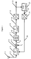
- Fig. 1
- is a receiver with a gain control loop having a rather large time constant;
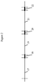
- Fig. 2
- is the structure of a DRM signal.
In a receiver with a long delay in the automatic gain control loop, a fast attack
time cannot be implemented. An example for such a receiver is shown in Fig. 1.
The invention is not limited to the gain control circuit shown in Fig. 1. It can be
applied to any gain control circuit to which the time constant for adjusting the
gain is rather high.
A RF signal 2 received via an antenna 1 is provided to a RF amplifier 3. An amplified
RF signal 4 is downconverted, by a oscillator 5, to an intermediate frequency
range. The oscillator 5 multiplies the amplified RF signal 4 with a signal of
constant frequency f0. The downconverted signal 6 is provided to an intermediate
frequency filter 7, and the filtered signal 8 is amplified by an IF amplifier 9. The
analogue IF signal 10 is converted, by an A/D converter 11, to a digital IF signal
12. The digital IF signal 12 serves as a starting point for further signal processing
and signal decoding. Besides that, the digital signal 12 is provided to an automatic
gain control unit 13, and there, the signal strength of the digital IF signal 12 is
compared to a reference magnitude. The automatic gain control unit 13 generates
a digital gain control signal 14 that is converted, by a D/A converter 15, into an
analogue gain control signal 16. The analogue gain control signal 16 is provided
to the RF amplifier 3, and the gain of said amplifier is varied in accordance with
the analogue gain control signal 16.
In the AGC loop shown in Fig. 1, the RF amplifier's gain is controlled by the
control signal, while the IF amplifier's output signal is used for deriving the gain
control signal. Between the RF amplifier 3 and the IF amplifier 9, the group delay
of the intermediate frequency filter 7 causes a time lag between the RF amplifier's
output and the gain control signal. This additional delay limits the attack time of
the closed-loop control circuit, and therefore, it takes a long time for the closed-loop
control circuit to adjust to a different signal strength.
Many broadcast stations transmit a certain program via a set of different frequencies.
On part of the receiver, the signal strengths of the broadcast signals received
at different frequencies may be compared. Then, the receiver may select a reception
frequency where the reception conditions are convincing. In order to monitor
the broadcast signals at various alternative frequencies, the receiver has to switch
from the current frequency to a possible alternative frequency, and back to the
current frequency, whereby the signal reception at said current frequency must
not be interrupted. Therefore, the time for switching the receiver's PLL (Phase
Locked Loop) to the alternative frequency, for setting the AGC gain to the new
gain value, for reading the data from the signal received at the alternative frequency,
for switching back the PLL to the original frequency, and for readjusting
the AGC gain to the original value is very short. The automatic gain control circuit
shown in Fig. 1 cannot be switched to a fast mode, because the AGC loop would
become instable.
In the following discussion, it is assumed that both the broadcast signal received
at the current frequency and the broadcast signals received at alternative frequencies
are signals according to the DRM (Digital Radio Mondiale) standard. In
Fig. 2, the structure of a DRM signal is shown as a function of time. The time
intervals 17, 19, 21 have an order of magnitude of about 1.2 sec. During these
time intervals, the data symbols that carry the bits and bytes of the respective
radio program's data stream are transmitted. Each of the long time intervals 17,
19, 21 is followed by a short time slot 18, 20, 22, and during these short time
slots of approximately 18,66 to 48 ms, static data symbols are transmitted. The
reception of static data symbols during the time slots 18, 20, 22 does not cause
any audible distortions for the listener.
The time slots 18, 20, 22 can therefore be used for monitoring alternative frequencies.
Monitoring an alternative frequency requires the steps of changing the
receiver's PLL to the alternative frequency, settling the gain of the receiver to the
signal strength at said alternative frequency, evaluating the received data, and
switching back to the current frequency. Because of the rather large settling time
of the automatic gain control circuit, it is impossible to perform all these tasks
during a single one of the time intervals 18, 20, 22.
According to the invention, the monitoring of a broadcast signal at an alternative
frequency is performed as follows: during a first one of the time slots for static
data symbol reception, for example during the time slot 18, the receiver's PLL is
switched to the alternative frequency, and the control loop of the gain control
circuit starts to adjust the gain to the signal strength of the broadcast signal
received at the alternative frequency. At the end of the time interval 18, the
receiver's gain has settled to the signal strength of the alternative signal. The
appropriate gain value corresponding to the alternative frequency is stored. For
example, the respective gain value might be stored in a register of a programmable
AGC circuit. At the end of the time slot 18, the PLL is switched back from the
alternative frequency to the current frequency, the gain value corresponding to
the current frequency is restored, and during the following time interval 19,
reception of the data stream transmitted at the current frequency is continued.
At the beginning of the time slot 20, the received frequency is again switched to
the alternative frequency, and the gain value corresponding to said alternative
frequency, which has been determined during the time slot 18, is written to the
receiver's gain control unit. In order to make sure that an overflow of the A/D
converter is avoided, the stored AGC gain should be slightly reduced before it is
written to the receiver's gain control unit. While a low input range of the A/D
converter can be handled by the digital signal processing, an ADC input signal
that is too high leads to a saturation of the A/D converter, and it becomes impossible
to check the broadcast signal at the alternative frequency. The AGC's "settling
time", which might have an order of magnitude of 10 to 20 ms, is replaced by
a "setting time" of less than 1 msec. At the beginning of the time slot 20, the gain
value is instantaneously switched to an appropriate value, and though the AGC's
time constant is rather high, decoding of the broadcast signal transmitted at the
alternative frequency can start immediately.
Next, it has to be checked whether the radio program transmitted at the alternative
frequency is identical to the radio program of the current frequency. For this
purpose, the bit stream received during the time slot 20, after the received frequency
has been set to the alternative frequency, is correlated to the bit stream
corresponding to the current frequency's radio program, which is already known
at the beginning of time slot 20. In case the radio programs transmitted at the
current frequency and at the alternative frequency are identical, it might make
sense to switch to the alternative frequency. Before doing that, it has to be checked
if the signal strength at the alternative frequency is indeed higher than the
signal strength at the present frequency. The signal strengths can e.g. be compared
by relating the gain value of the alternative frequency to the gain value of the
present frequency. In case the signal strength at said alternative frequency exceeds
the signal strength at the current frequency by a predefined amount, it can
be concluded that a change of the PLL's frequency would considerably improve the
reception conditions. In this case, the received frequency is switched over to the
alternative frequency, and the reception of the current audio program is continued
at the alternative frequency.
The two tasks of correlating the bit streams transmitted at the present frequency
and at the alternative frequency and of comparing the signal strengths may be
performed in arbitrary order, and they might as well be performed in parallel.
Both tasks are performed during the time slot 20, and at the end of time slot 20,
it is clear whether frequency switching should be performed or not.
The invention might as well be used for monitoring a whole set of alternative
frequencies. There do exist radio stations that broadcast their radio programs at a
multitude of different frequencies. For each one of said alternative frequencies, a
separate gain value might be determined and stored in a dedicated register. As
soon as these gain values are available, it becomes possible to quickly switch from
one frequency to another frequency without been restricted by the AGC's settling
time. The signal strengths and the programs at several alternative frequencies can
be monitored during the reception of the current frequency's broadcast signal.
Then, the frequency channel with the best reception conditions can be selected.
The invention can also be used for checking alternative frequencies when receiving
a FM broadcast signal. FM signals do not comprise a time slot structure as
shown in Fig. 2. When switching the received frequency to an alternative frequency,
the gain level of the automatic gain control is set to a predefined gain value
that corresponds to the expected signal strength at said alternative frequency. For
example, for each alternative frequency of a set of alternative frequencies, a
corresponding gain value might be stored, e.g. in a table maintained in the gain
control circuitry. Whenever a certain alternative frequency is monitored, the
corresponding gain value is written to the automatic gain control. The time period
for adjusting the receiver's gain to the alternative frequency signal is considerably
reduced.
Another strategy is to use the gain value at the present frequency as a starting
point, and to decrease said gain value by a predefined amount. The dynamic range
of a FM receiver's input signal covers about 120 dB, and therefore, the AGC gain
at the present frequency might for example be reduced by 40 dB or more (depending
on the current signal strength) when switching to an alternative frequency.
In case the signal strength of the FM signal at said alternative frequency is considerably
higher than the signal strength at the present frequency, there is a low
risk that saturation of the control circuit's A/D converter occurs, and processing
of the received can start immediately. In case the FM signal received at the alternative
frequency is weak, the gain level (which has been reduced by 40 dB) might
be to small. This doesn't matter, though, because a FM signal with a low signal
strength is not worth to be analysed anyway. Another strategy is to iteratively
reduce the gain value, for example in steps of 20 or 40 dB, when checking a FM
signal at an alternative frequency.
Next, the signal strength at the alternative frequency is determined. The receiver
determines the signal strength of the FM signal received at the alternative frequency
by combining the knowledge of the AGC gain and the measurement of the
FM signal's amplitude. Then, in a second step, the receiver starts decoding the FM
data. In particular, the PI (Program Information) of the radio program transmitted
at the alternative frequency can be obtained by decoding the RDS (Radio Data
System) signal component of the FM signal. By comparing the PI code of the
alternative frequency's radio program with the PI code of the current radio program,
it is possible to determine whether the programs are identical or not. In
case the signal strength at the alternative frequency is considerably higher than
the signal strength at the present frequency, and in case the programs are identical,
it makes sense to switch to the alternative frequency and to continue receiving
said radio program at the alternative frequency. The listener might not even
notice that the received frequency has been changed.
List of Reference Symbols
- 1
- antenna
- 2
- RF signal
- 3
- RF amplifier
- 4
- amplified RF signal
- 5
- oscillator
- 6
- downconverted signal
- 7
- intermediate frequency filter
- 8
- filtered signal
- 9
- IF amplifier
- 10
- analogue IF signal
- 11
- A/D converter
- 12
- digital IF signal
- 13
- automatic gain control unit
- 14
- digital gain control signal
- 15
- D/A converter
- 16
- analogue gain control signal
- 17, 19, 21
- time intervals
- 18, 20, 22
- time slots