EP1424255B1 - Electro mechanical brake, control device and control methods - Google Patents
Electro mechanical brake, control device and control methods Download PDFInfo
- Publication number
- EP1424255B1 EP1424255B1 EP03026841A EP03026841A EP1424255B1 EP 1424255 B1 EP1424255 B1 EP 1424255B1 EP 03026841 A EP03026841 A EP 03026841A EP 03026841 A EP03026841 A EP 03026841A EP 1424255 B1 EP1424255 B1 EP 1424255B1
- Authority
- EP
- European Patent Office
- Prior art keywords
- braking
- electro
- mechanical
- brake mechanism
- vehicle
- Prior art date
- Legal status (The legal status is an assumption and is not a legal conclusion. Google has not performed a legal analysis and makes no representation as to the accuracy of the status listed.)
- Expired - Fee Related
Links
- 238000000034 method Methods 0.000 title claims description 10
- 230000007246 mechanism Effects 0.000 claims description 67
- 230000004044 response Effects 0.000 claims description 5
- 230000003213 activating effect Effects 0.000 claims description 3
- 230000005540 biological transmission Effects 0.000 claims 1
- 230000001133 acceleration Effects 0.000 description 8
- 238000010586 diagram Methods 0.000 description 8
- 239000007858 starting material Substances 0.000 description 6
- 238000001514 detection method Methods 0.000 description 4
- 230000007935 neutral effect Effects 0.000 description 4
- 230000004913 activation Effects 0.000 description 2
- 238000012790 confirmation Methods 0.000 description 2
- 230000008569 process Effects 0.000 description 1
- 230000000284 resting effect Effects 0.000 description 1
Images


Classifications
-
- B—PERFORMING OPERATIONS; TRANSPORTING
- B60—VEHICLES IN GENERAL
- B60T—VEHICLE BRAKE CONTROL SYSTEMS OR PARTS THEREOF; BRAKE CONTROL SYSTEMS OR PARTS THEREOF, IN GENERAL; ARRANGEMENT OF BRAKING ELEMENTS ON VEHICLES IN GENERAL; PORTABLE DEVICES FOR PREVENTING UNWANTED MOVEMENT OF VEHICLES; VEHICLE MODIFICATIONS TO FACILITATE COOLING OF BRAKES
- B60T13/00—Transmitting braking action from initiating means to ultimate brake actuator with power assistance or drive; Brake systems incorporating such transmitting means, e.g. air-pressure brake systems
- B60T13/74—Transmitting braking action from initiating means to ultimate brake actuator with power assistance or drive; Brake systems incorporating such transmitting means, e.g. air-pressure brake systems with electrical assistance or drive
- B60T13/741—Transmitting braking action from initiating means to ultimate brake actuator with power assistance or drive; Brake systems incorporating such transmitting means, e.g. air-pressure brake systems with electrical assistance or drive acting on an ultimate actuator
-
- B—PERFORMING OPERATIONS; TRANSPORTING
- B60—VEHICLES IN GENERAL
- B60T—VEHICLE BRAKE CONTROL SYSTEMS OR PARTS THEREOF; BRAKE CONTROL SYSTEMS OR PARTS THEREOF, IN GENERAL; ARRANGEMENT OF BRAKING ELEMENTS ON VEHICLES IN GENERAL; PORTABLE DEVICES FOR PREVENTING UNWANTED MOVEMENT OF VEHICLES; VEHICLE MODIFICATIONS TO FACILITATE COOLING OF BRAKES
- B60T13/00—Transmitting braking action from initiating means to ultimate brake actuator with power assistance or drive; Brake systems incorporating such transmitting means, e.g. air-pressure brake systems
- B60T13/10—Transmitting braking action from initiating means to ultimate brake actuator with power assistance or drive; Brake systems incorporating such transmitting means, e.g. air-pressure brake systems with fluid assistance, drive, or release
- B60T13/66—Electrical control in fluid-pressure brake systems
-
- B—PERFORMING OPERATIONS; TRANSPORTING
- B60—VEHICLES IN GENERAL
- B60T—VEHICLE BRAKE CONTROL SYSTEMS OR PARTS THEREOF; BRAKE CONTROL SYSTEMS OR PARTS THEREOF, IN GENERAL; ARRANGEMENT OF BRAKING ELEMENTS ON VEHICLES IN GENERAL; PORTABLE DEVICES FOR PREVENTING UNWANTED MOVEMENT OF VEHICLES; VEHICLE MODIFICATIONS TO FACILITATE COOLING OF BRAKES
- B60T7/00—Brake-action initiating means
- B60T7/12—Brake-action initiating means for automatic initiation; for initiation not subject to will of driver or passenger
- B60T7/122—Brake-action initiating means for automatic initiation; for initiation not subject to will of driver or passenger for locking of reverse movement
-
- B—PERFORMING OPERATIONS; TRANSPORTING
- B60—VEHICLES IN GENERAL
- B60T—VEHICLE BRAKE CONTROL SYSTEMS OR PARTS THEREOF; BRAKE CONTROL SYSTEMS OR PARTS THEREOF, IN GENERAL; ARRANGEMENT OF BRAKING ELEMENTS ON VEHICLES IN GENERAL; PORTABLE DEVICES FOR PREVENTING UNWANTED MOVEMENT OF VEHICLES; VEHICLE MODIFICATIONS TO FACILITATE COOLING OF BRAKES
- B60T2201/00—Particular use of vehicle brake systems; Special systems using also the brakes; Special software modules within the brake system controller
- B60T2201/06—Hill holder; Start aid systems on inclined road
Definitions
- This invention relates to an electro-mechanical brake device for an automobile, and more particularly to a parking mechanism and a control method of maintaining a braking force even when a power supply is turned off.
- JP-A-2001-163198 discloses a vehicle control device in which a braking force maintaining instruction is outputted to a braking device when an automatic stall condition of an engine is satisfied.
- the braking force maintaining instruction output and the braking force releasing control are carried out based on an automatic engine stop condition, an automatic engine stop release condition and restart condition of the engine.
- any consideration has not been paid to the fact that the braking force is to be maintained at the time when the vehicle is parked on a way of a slope road. This causes a problem that the braking force maintaining control is not performed in case that the vehicle is suddenly stopped by turning off an ignition key switch on a way of the slope road. In that case, there is a possibility that the vehicle is ready to move down along the slope road.
- DE 198 26 130 Al relates to an electromechanical, brake-by-wire braking system for a motor vehicle, comprising control units responsive to a driver's requirement, for controlling brake actuators each including an electric motor and a locking arrangement.
- brake actuators each including an electric motor and a locking arrangement.
- the locking arrangement is first of all released, closed again after actuation has been terminated.
- DE 198 38 886 Al describes an electric parking brake system for a vehicle including an electric control unit that controls a brake device and an operating element for actuating the electric parking brake system.
- an electric control unit that controls a brake device and an operating element for actuating the electric parking brake system.
- actuation of the operating element alternatively applies and releases the electric parking brake according to the driver's request.
- this invention provides a control device and a method controlling the same according to claims 1 and 8.
- the control device detects whether a braking pedal is stepped on or a brake operation signal is present and also detects that the ignition key switch or the power supply switch of the vehicle is turned off, and/or further controls the parking brake mechanism so that the braking force may be maintained on the basis of these detection results.
- a motor for generating the braking force is driven on the basis of the detection results describe above, and the parking brake mechanism for maintaining the braking force is operated at the time when the braking force reaches a predetermined value.
- An electro-mechanical braking control device can comprise an electro-mechanical brake for electrically generating a braking force in response to a stroking force and/or a stroking speed of a braking pedal, and/or a braking operation signal.
- a parking brake mechanism can be provided for maintaining the braking force when power is not supplied to said electro-mechanical brake and/or a control signal thereto is turned off, wherein when the braking pedal is stroked and/or the braking operation signal is detected, said parking-brake mechanism can be controlled such that the braking force can be maintained by said electro-mechanical brake.
- control device can perform a control processing based on a stroking force and/or a stroking speed of a braking pedal and/or a braking operation signal.
- the parking brake mechanism can be controlled when the braking pedal is stepped on and/or the braking operation signal is detected.
- an electro-mechanical braking device including an electro-mechanical brake for electrically generating a braking force in response to a stroking force and/or a stroking speed of a braking pedal, and/or a braking operation signal.
- said control method can comprise the step of controlling said parking brake mechanism to maintain the braking force of said electro-mechanical brake when the stroking force and/or stroking speed of the braking pedal, and/or the braking operation signal is detected, or the braking pedal is stepped on and/or the braking operation signal is provided.
- This invention provides the electro-mechanical parking brake mechanism for maintaining the braking force even when the power supply switch is turned off.
- the parking brake mechanism is activated (the braking force is maintained) when an ignition key switch or the power supply switch of the vehicle is turned off under the condition that the braking pedal is stepped on or the braking operation signal is present.
- the motor for generating the braking force is driven, and the parking brake mechanism for maintaining the braking force is activated at the time when the braking force reaches a predetermined value.
- the braking force is maintained by the parking brake mechanism, so that the vehicle may be parked in case the vehicle is stopped on a way of the slope road.
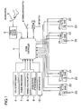
- Fig. 1 is a diagram showing a system constitution of this invention.
- a braking controller 1 receives input signals such as a signal from a braking stroke sensor 3 for sensing a stroke amount of a braking pedal 2 by a driver, a signal from a parking brake switch 4 for turning on or off an activation of the parking brake mechanism, a signal from a key switch 5 or a power supply switch (or an ignition key switch) of the vehicle, a signal from a vehicle speed sensor 6 for sensing a speed of the vehicle, a signal from an engine speed sensor 7 for sensing an engine speed, a signal from a parking/neutral switch 8 which indicates whether a gear is connected or not connected (ON indicates a non-connection state and OFF indicates a connection state), a signal from an acceleration stroke sensor 9 for sensing a stroke amount of an acceleration pedal by the driver, and a signal from a starter switch 10 which indicates whether or not an starter of the engine is started up.
- signals such as a signal from a braking stroke sensor 3 for sensing
- the braking controller 1 On the basis of the input signals described above, the braking controller 1 outputs a control signal for obtaining a necessary braking force to an electro-mechanical brake (EMB) 22.
- EMB electro-mechanical brake
- the input signals inputted to the braking controller as described above, the contents processed in the controller and the output signals outputted from the controller are not limited to the contents described above, but can include all of contents necessary for controlling the electro-mechanical brake. Also, the brake controller as described above can be incorporated into another control unit such as an engine control unit.
- Fig. 2 is an explanatory diagram showing the electro-mechanical brake (EMB) 22 provided with a parking brake mechanism.
- the electro-mechanical brake (EMB) 22 includes a motor 221, a screw mechanism unit 222 for converting a rotational movement of the motor into a reciprocal movement of the screw, a lock mechanism unit 225 for mechanically locking the reciprocal movement of the screw of the screw mechanism unit, an electro-mechanical parking brake mechanism unit 21 for switching between locking (fixing)/unlocking (loosing) of the lock mechanism unit, a braking pad 224 for generating a predetermined braking force by pressing the screw mechanism unit against a brake disc 23, and a braking force sensor 223 for detecting an actual braking force.
- the electro-mechanical parking brake mechanism unit 21 includes a motor 211 such as a small sized motor and a screw mechanism unit 212 so that the screw mechanism of the electro-mechanical brake may be fixed or released by a driving force of the motor 211.
- the electro-mechanical parking brake mechanism unit 21 and/or the lock mechanism unit 225 may lock the screw mechanism unit 222 under the condition that the braking pad 224 is being pressed against the brake disc 23 until a predetermined braking force is obtained from a rotational force of the motor 221.
- the braking force is maintained even when the rotational force (electric current value) of the motor 221 is made equal to zero (0).
- the mechanism, configuration, structure and operation of the electro-mechanical brake and those of the parking brake merely indicate one example of this invention, and it is also possible to employ a mechanism using only the rotational movement of the motor, and another mechanism other than the screw mechanism in order to convert the rotational movement into the reciprocal movement.
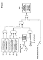
- Fig. 3 shows one example of a logic circuit diagram for activating the electro-mechanical parking brake mechanism by the braking controller of this invention.
- the electro-mechanical parking brake mechanism is activated to maintain the braking force under the condition that the braking pedal 2 is in on state (stepped on), and the key switch 5 (power supply switch of the vehicle) is turned off, and a speed of the vehicle is equal to 0 km/h (parked) or the engine speed is equal to 0 rpm (stopped), and the parking/neutral switch is turned on (the gear is not connected), and the acceleration stroke is equal to 0 mm (the acceleration pedal is not stepped on), and the starter switch is turned off (the starter is not started up).
- the key switch 5 power supply switch of the vehicle
- the electro-mechanical parking brake mechanism is activated to maintain the braking force.
- the conditions as shown in Fig. 3 become the signals from each of the sensors (for example, 6, 7, 8, 9, and 10 in the Figure). The contents of these conditions are adopted in order to detect that the vehicle is completely parked and the driver has no intention of starting the vehicle.
- the electro-mechanical parking brake mechanism may be activated to maintain the braking force.
- the value of maintaining the braking force is selected from either one of a value corresponding to a stroke amount or stroke force of the braking pedal 2, a value obtained from correcting the stroking value or a predetermined value.
- Fig. 4 shows one example of the logic circuit diagram for cancelling the braking force of the electro-mechanical parking brake mechanism through the braking controller of this invention.
- the electro-mechanical parking brake mechanism is released to maintain the braking force equal to zero, namely, the braking disc 23 is loosened under the conditions that the key switch 5 (power supply switch of the vehicle) is turned on with the braking pedal 2 being off state (not stepped on), and, when the engine speed is equal to, for example, 500 rpm (the starting of the engine is completed), the parking/neutral switch is turned off (the gear is connected) or the acceleration stroke is more than 0 mm (the acceleration pedal is stepped on) or the starter switch is turned off (the starter is not started up).
- the key switch 5 power supply switch of the vehicle
- the parking/neutral switch is turned off (the gear is connected) or the acceleration stroke is more than 0 mm (the acceleration pedal is stepped on) or the starter switch is turned off (the starter is not started up).
- the motor 221 and the screw mechanism unit 222 are driven to release the electro-mechanical parking brake mechanism so that the braking force is maintained to be zero to loose the brake disc 23.
- the engine speed more than 500 rpm as shown in Fig. 4 indicates the detection or confirmation of the fact that the starting of the engine is completed. Also, the parking/neutral switch being turned off (the gear being connected) and the acceleration stroke being more than 0 mm (the acceleration pedal being stepped on) indicate the detection or confirmation of the fact that the driver has intention of starting the vehicle. In case the vehicle such as an electric-powered vehicle or a hybrid electric vehicle is started by the motor, the engine speed being more than 500 rpm is not required owing to no provision of the engine.
- Figs. 5 and 6 show flowcharts of this invention, respectively.
- the brake controller performs processes of the flowcharts based on the input signals applied thereto.
- a step 90 performs an input processing for various kinds of signals.
- a step 100 determines whether the conditions shown in Fig. 3 are satisfied or not. If satisfied (YES), a step 101 performs the processing of activating the electro-mechanical parking brake mechanism to maintain the braking force, and then terminates the processing. If not satisfied (NO), a step 102 determines whether the conditions as shown in Fig. 4 are satisfied or not. If satisfied (YES), the electro-mechanical parking brake mechanism is released to maintain the braking force to be zero. Namely, in this embodiment, the motor 221 and the screw mechanism unit 222 are driven to loose the braking disc 23, and then the processing is terminated.
- step 102 performing the processing of determining whether the conditions are satisfied or not, if not satisfied (NO), the processing goes to a step 200 shown in Fig. 6 .
- the step 200 shown in Fig. 6 determines whether the electro-mechanical brake (EMB) 22 is unlocked or not (the braking force is maintained to be zero). In this embodiment, the processing is determined depending on the fact that an activation position of the small-sized motor 211 of the electro-mechanical parking brake mechanism 21 corresponds to either one of the fixing or loosing states of the screw mechanism of the electro-mechanical brake. If YES, a step 201 determines whether the conditions for a normal electro-mechanical brake control are satisfied or not. If NO, the electro-mechanical brake is locked, and then the processing is terminated.
- EMB electro-mechanical brake
- a step 202 performs the processing of controlling an electro-mechanical braking motor 221 so that the braking force may correspond to a braking stroke amount (stroking amount of the braking pedal). If NO, a step 203 performs the processing of controlling the motor 221 to maintain the braking force of the electro-mechanical brake to be zero, and then the processing is terminated.
- the parking-brake mechanism is provided to maintain the braking force even when the power supply switch is turned off.
- the parking brake mechanism is activated (the braking force is maintained).
- the motor for generating the braking force is driven to activate the braking force maintaining parking brake mechanism at the time when the braking force reaches a predetermined value. Even when the power supply to the motor for generating the braking force is turned off, the braking force is maintained by the parking brake mechanism so that the vehicle may be securely stopped when the vehicle is parked on a way of the slope road.
- a logic operation of the input signals is performed to determine whether the braking force is maintained by the parking brake mechanism or not. If it is necessity to maintain the braking force, then it is controlled that the braking force is provided to the electro-mechanical brake. Accordingly, the vehicle is securely stopped without movement on a way of the slope road with the braking force being maintained.
Landscapes
- Engineering & Computer Science (AREA)
- Transportation (AREA)
- Mechanical Engineering (AREA)
- Regulating Braking Force (AREA)
- Braking Systems And Boosters (AREA)
- Electric Propulsion And Braking For Vehicles (AREA)
Description
- This invention relates to an electro-mechanical brake device for an automobile, and more particularly to a parking mechanism and a control method of maintaining a braking force even when a power supply is turned off.
-
JP-A-2001-163198 - In the patent document mentioned above, the braking force maintaining instruction output and the braking force releasing control are carried out based on an automatic engine stop condition, an automatic engine stop release condition and restart condition of the engine. However, any consideration has not been paid to the fact that the braking force is to be maintained at the time when the vehicle is parked on a way of a slope road. This causes a problem that the braking force maintaining control is not performed in case that the vehicle is suddenly stopped by turning off an ignition key switch on a way of the slope road. In that case, there is a possibility that the vehicle is ready to move down along the slope road.
-
DE 198 26 130 Al relates to an electromechanical, brake-by-wire braking system for a motor vehicle, comprising control units responsive to a driver's requirement, for controlling brake actuators each including an electric motor and a locking arrangement. For actuating a wheel brake via its electric motor, the locking arrangement is first of all released, closed again after actuation has been terminated. -
DE 198 38 886 Al describes an electric parking brake system for a vehicle including an electric control unit that controls a brake device and an operating element for actuating the electric parking brake system. When the vehicle is in a resting position, actuation of the operating element alternatively applies and releases the electric parking brake according to the driver's request. - In order to solve the problem as mentioned above, this invention provides a control device and a method controlling the same according to
claims - The control device detects whether a braking pedal is stepped on or a brake operation signal is present and also detects that the ignition key switch or the power supply switch of the vehicle is turned off, and/or further controls the parking brake mechanism so that the braking force may be maintained on the basis of these detection results.
- Also, in order to maintain the braking force of the parking brake mechanism, a motor for generating the braking force is driven on the basis of the detection results describe above, and the parking brake mechanism for maintaining the braking force is operated at the time when the braking force reaches a predetermined value.
- An electro-mechanical braking control device according to the present invention can comprise an electro-mechanical brake for electrically generating a braking force in response to a stroking force and/or a stroking speed of a braking pedal, and/or a braking operation signal.
- Further a parking brake mechanism can be provided for maintaining the braking force when power is not supplied to said electro-mechanical brake and/or a control signal thereto is turned off, wherein when the braking pedal is stroked and/or the braking operation signal is detected, said parking-brake mechanism can be controlled such that the braking force can be maintained by said electro-mechanical brake.
- According to be present invention the control device can perform a control processing based on a stroking force and/or a stroking speed of a braking pedal and/or a braking operation signal.
- The parking brake mechanism can be controlled when the braking pedal is stepped on and/or the braking operation signal is detected.
- According to the present invention, there can be executed a control method for controlling an electro-mechanical braking device including an electro-mechanical brake for electrically generating a braking force in response to a stroking force and/or a stroking speed of a braking pedal, and/or a braking operation signal.
- Further, said control method can comprise the step of controlling said parking brake mechanism to maintain the braking force of said electro-mechanical brake when the stroking force and/or stroking speed of the braking pedal, and/or the braking operation signal is detected, or the braking pedal is stepped on and/or the braking operation signal is provided.
- Other objects, features and advantages of the invention will become apparent from the following description of the embodiments of the invention taken in conjunction with the accompanying drawings.
-
-
Fig. 1 is a diagram showing the constitution of this invention. -
Fig. 2 is an explanatory diagram of an electro-mechanical braking device provided with a parking brake mechanism according to this invention. -
Fig. 3 is an operation logic circuit diagram of the parking brake mechanism of this invention. -
Fig. 4 is a release logic circuit diagram of the parking brake mechanism of this invention. -
Fig. 5 is a flowchart of this invention. -
Fig. 6 is another flowchart of this invention. - This invention provides the electro-mechanical parking brake mechanism for maintaining the braking force even when the power supply switch is turned off. In this invention, the parking brake mechanism is activated (the braking force is maintained) when an ignition key switch or the power supply switch of the vehicle is turned off under the condition that the braking pedal is stepped on or the braking operation signal is present.
- Also, when the power supply switch (the ignition key switch) of the vehicle is turned off with the braking pedal being stepped on, the motor for generating the braking force is driven, and the parking brake mechanism for maintaining the braking force is activated at the time when the braking force reaches a predetermined value.
- According to this invention, even when the power supply to the motor for generating the braking force is turned off, the braking force is maintained by the parking brake mechanism, so that the vehicle may be parked in case the vehicle is stopped on a way of the slope road.
- Hereinafter, referring to the drawings, one embodiment of this invention is described in detail. However, this invention is not limited to the embodiment described below.
-
Fig. 1 is a diagram showing a system constitution of this invention. Abraking controller 1 receives input signals such as a signal from abraking stroke sensor 3 for sensing a stroke amount of abraking pedal 2 by a driver, a signal from aparking brake switch 4 for turning on or off an activation of the parking brake mechanism, a signal from akey switch 5 or a power supply switch (or an ignition key switch) of the vehicle, a signal from a vehicle speed sensor 6 for sensing a speed of the vehicle, a signal from anengine speed sensor 7 for sensing an engine speed, a signal from a parking/neutral switch 8 which indicates whether a gear is connected or not connected (ON indicates a non-connection state and OFF indicates a connection state), a signal from anacceleration stroke sensor 9 for sensing a stroke amount of an acceleration pedal by the driver, and a signal from astarter switch 10 which indicates whether or not an starter of the engine is started up. - On the basis of the input signals described above, the
braking controller 1 outputs a control signal for obtaining a necessary braking force to an electro-mechanical brake (EMB) 22. The input signals inputted to the braking controller as described above, the contents processed in the controller and the output signals outputted from the controller are not limited to the contents described above, but can include all of contents necessary for controlling the electro-mechanical brake. Also, the brake controller as described above can be incorporated into another control unit such as an engine control unit. -
Fig. 2 is an explanatory diagram showing the electro-mechanical brake (EMB) 22 provided with a parking brake mechanism. The electro-mechanical brake (EMB) 22 includes amotor 221, ascrew mechanism unit 222 for converting a rotational movement of the motor into a reciprocal movement of the screw, alock mechanism unit 225 for mechanically locking the reciprocal movement of the screw of the screw mechanism unit, an electro-mechanical parkingbrake mechanism unit 21 for switching between locking (fixing)/unlocking (loosing) of the lock mechanism unit, abraking pad 224 for generating a predetermined braking force by pressing the screw mechanism unit against abrake disc 23, and abraking force sensor 223 for detecting an actual braking force. - The electro-mechanical parking
brake mechanism unit 21 includes amotor 211 such as a small sized motor and ascrew mechanism unit 212 so that the screw mechanism of the electro-mechanical brake may be fixed or released by a driving force of themotor 211. According to such configuration, the electro-mechanical parkingbrake mechanism unit 21 and/or thelock mechanism unit 225 may lock thescrew mechanism unit 222 under the condition that thebraking pad 224 is being pressed against thebrake disc 23 until a predetermined braking force is obtained from a rotational force of themotor 221. As a result, the braking force is maintained even when the rotational force (electric current value) of themotor 221 is made equal to zero (0). - The mechanism, configuration, structure and operation of the electro-mechanical brake and those of the parking brake merely indicate one example of this invention, and it is also possible to employ a mechanism using only the rotational movement of the motor, and another mechanism other than the screw mechanism in order to convert the rotational movement into the reciprocal movement.
-
Fig. 3 shows one example of a logic circuit diagram for activating the electro-mechanical parking brake mechanism by the braking controller of this invention. The electro-mechanical parking brake mechanism is activated to maintain the braking force under the condition that thebraking pedal 2 is in on state (stepped on), and the key switch 5 (power supply switch of the vehicle) is turned off, and a speed of the vehicle is equal to 0 km/h (parked) or the engine speed is equal to 0 rpm (stopped), and the parking/neutral switch is turned on (the gear is not connected), and the acceleration stroke is equal to 0 mm (the acceleration pedal is not stepped on), and the starter switch is turned off (the starter is not started up). - In case the driver turns on the
parking brake switch 4 regardless of these conditions indicated above, the electro-mechanical parking brake mechanism is activated to maintain the braking force. - The conditions as shown in
Fig. 3 become the signals from each of the sensors (for example, 6, 7, 8, 9, and 10 in the Figure). The contents of these conditions are adopted in order to detect that the vehicle is completely parked and the driver has no intention of starting the vehicle. - In case, regardless of these conditions indicated above, the key switch is turned off with the braking pedal being stepped on, it is determined that the driver basically has an intention of stopping the vehicle. Accordingly, the electro-mechanical parking brake mechanism may be activated to maintain the braking force. The value of maintaining the braking force is selected from either one of a value corresponding to a stroke amount or stroke force of the
braking pedal 2, a value obtained from correcting the stroking value or a predetermined value. -
Fig. 4 shows one example of the logic circuit diagram for cancelling the braking force of the electro-mechanical parking brake mechanism through the braking controller of this invention. The electro-mechanical parking brake mechanism is released to maintain the braking force equal to zero, namely, thebraking disc 23 is loosened under the conditions that the key switch 5 (power supply switch of the vehicle) is turned on with thebraking pedal 2 being off state (not stepped on), and, when the engine speed is equal to, for example, 500 rpm (the starting of the engine is completed), the parking/neutral switch is turned off (the gear is connected) or the acceleration stroke is more than 0 mm (the acceleration pedal is stepped on) or the starter switch is turned off (the starter is not started up). - In case, regardless of the conditions indicated above, the driver turnes off the
parking brake switch 4, themotor 221 and thescrew mechanism unit 222 are driven to release the electro-mechanical parking brake mechanism so that the braking force is maintained to be zero to loose thebrake disc 23. - The engine speed more than 500 rpm as shown in
Fig. 4 indicates the detection or confirmation of the fact that the starting of the engine is completed. Also, the parking/neutral switch being turned off (the gear being connected) and the acceleration stroke being more than 0 mm (the acceleration pedal being stepped on) indicate the detection or confirmation of the fact that the driver has intention of starting the vehicle. In case the vehicle such as an electric-powered vehicle or a hybrid electric vehicle is started by the motor, the engine speed being more than 500 rpm is not required owing to no provision of the engine. -
Figs. 5 and6 show flowcharts of this invention, respectively. The brake controller performs processes of the flowcharts based on the input signals applied thereto. Astep 90 performs an input processing for various kinds of signals. Astep 100, for example, determines whether the conditions shown inFig. 3 are satisfied or not. If satisfied (YES), astep 101 performs the processing of activating the electro-mechanical parking brake mechanism to maintain the braking force, and then terminates the processing. If not satisfied (NO), astep 102 determines whether the conditions as shown inFig. 4 are satisfied or not. If satisfied (YES), the electro-mechanical parking brake mechanism is released to maintain the braking force to be zero. Namely, in this embodiment, themotor 221 and thescrew mechanism unit 222 are driven to loose thebraking disc 23, and then the processing is terminated. - In the
step 102 performing the processing of determining whether the conditions are satisfied or not, if not satisfied (NO), the processing goes to astep 200 shown inFig. 6 . - The
step 200 shown inFig. 6 determines whether the electro-mechanical brake (EMB) 22 is unlocked or not (the braking force is maintained to be zero). In this embodiment, the processing is determined depending on the fact that an activation position of the small-sized motor 211 of the electro-mechanicalparking brake mechanism 21 corresponds to either one of the fixing or loosing states of the screw mechanism of the electro-mechanical brake. If YES, astep 201 determines whether the conditions for a normal electro-mechanical brake control are satisfied or not. If NO, the electro-mechanical brake is locked, and then the processing is terminated. - If YES in the
step 201, astep 202 performs the processing of controlling an electro-mechanical braking motor 221 so that the braking force may correspond to a braking stroke amount (stroking amount of the braking pedal). If NO, astep 203 performs the processing of controlling themotor 221 to maintain the braking force of the electro-mechanical brake to be zero, and then the processing is terminated. - As described above, according to this invention, the parking-brake mechanism is provided to maintain the braking force even when the power supply switch is turned off. When the power supply switch (ignition key switch) of the vehicle is turned off with the braking pedal being stepped on or the braking operation signal being present, the parking brake mechanism is activated (the braking force is maintained). In case the power supply switch (ignition key switch) of the vehicle is turned off with the braking pedal being stepped on, the motor for generating the braking force is driven to activate the braking force maintaining parking brake mechanism at the time when the braking force reaches a predetermined value. Even when the power supply to the motor for generating the braking force is turned off, the braking force is maintained by the parking brake mechanism so that the vehicle may be securely stopped when the vehicle is parked on a way of the slope road.
- According to this invention, when the power supply or the control signal to the motor for generating the braking force is turned off, a logic operation of the input signals is performed to determine whether the braking force is maintained by the parking brake mechanism or not. If it is necessity to maintain the braking force, then it is controlled that the braking force is provided to the electro-mechanical brake. Accordingly, the vehicle is securely stopped without movement on a way of the slope road with the braking force being maintained.
Claims (10)
- An electro-mechanical braking control device comprising:an electro-mechanical brake (22) for electrically generating a braking force in response to a stroking force or stroking speed of a braking pedal (2), or a braking operation signal, anda parking brake mechanism (21) for maintaining the braking force when power is not supplied to said electro-mechanical brake or a control signal thereto is turned off,wherein when the braking pedal (2) is stepped on or the braking operation signal is detected, said parking-brake mechanism (21) is controlled so that the braking force may be maintained by said electro-mechanical brake (22),characterized in that,the electro-mechanical braking control device is configured such that when the braking pedal (2) is stepped on or the braking operation signal is detected, depending on a state of power supply switch or an ignition key switch (5) of a vehicle, it is determined whether the braking force of said electro-mechanical brake (22) is maintained by said parking-brake mechanism (21) or not.
- An electro-mechanical braking control device according to Claim 1, characterized in that when said power supply switch or said ignition key switch (5) of the vehicle is turned off, the braking force of said electro-mechanical brake (22) is maintained by said parking-brake mechanism (21).
- An electro-mechanical braking control device according to Claim 1 or 2, characterized in that, when it is detected that a power supply switch or an ignition key switch (5) of a vehicle is turned on, and the braking pedal (2) is not stepped on or a braking operation is not performed in accordance with the braking operation signal, and, when an engine speed is larger than a predetermined value and a transmission is connected, said parking-brake mechanism (21) is activated to cancel the braking force by said electro-mechanical brake (22).
- An electro-mechanical braking control device according to at least one of Claims 1 to 3, characterized in that, when it is detected that a power supply switch or an ignition key switch (5) of a vehicle is turned on, and the braking pedal (2) is not stepped on or a braking operation is not performed in accordance with the braking operation signal, and when a driving torque of a motor for driving a vehicle is generated with a gear for the motor being connected, said parking-brake mechanism (21) is activated to cancel the braking force of said electro-mechanical brake (22).
- An electro-mechanical braking device for electrically generating a braking force in response to a control signal from a control device (1) performing a control processing based on at least one of a stroking force and a stroking speed of a braking pedal (2), and a braking operation signal,
said electro-mechanical braking device (22)
comprising a parking-brake mechanism (21) for maintaining the braking force when power is not supplied thereto or the control signal is not supplied thereto,
wherein said parking brake mechanism (21) is controlled when the braking pedal (2) is stepped on or the braking operation signal is detected,
characterized in that,
the electro-mechanical braking device is configured such that when the braking pedal (2) is stepped on or the braking operation signal is detected, and a power supply switch or an ignition key switch (5) of a vehicle is turned off, said parking-brake mechanism (21) is activated to maintain the braking force. - An electro-mechanical braking device according to Claim 5, characterized in that, when a power supply switch or an ignition key switch (5) of a vehicle is turned on, and the braking pedal (2) is not stepped on, it is detected from the braking operation signal that the braking pedal (2) is not stepped on or the braking operation is not performed, and it is detected that the engine speed is larger than a predetermined value and a gear is connected, then said parking-brake mechanism (21) is released.
- An electro-mechanical braking device according to Claim 5 or 6, characterized in that, when a power supply switch or an ignition key switch (5) of an electric powered vehicle or a hybrid electric vehicle is turned on, and the braking pedal (2) is not stepped on, or it is detected from the braking operation signal that the braking pedal (2) is not stepped on or the braking operation is not performed, and when it is detected that a motor for driving the vehicle and a gear thereof are connected with each other, and a driving torque is generated, then said parking brake mechanism (21) is released.
- A control method for controlling an electro-mechanical braking device including an electro-mechanical brake (22) for electrically generating a braking force in response to a stroking force or a stroking speed of a braking pedal (2), or a braking operation signal, and a parking brake mechanism (21) for maintaining the braking force when power is not supplied to said electro-mechanical brake (22) or a control signal is not applied thereto, said control method comprising at least the step of controlling said parking brake mechanism (21) to maintain the braking force of said electro-mechanical brake (22) when the stroking force or stroking speed of the braking pedal (2) or the braking operation signal is detected, or the braking pedal (2) is stepped on or the braking operation signal is provided,
characterized in that,
the step of controlling said parking brake mechanism (21) comprises a step of maintaining the braking force of said electro-mechanical brake (22) when it is detected that a power supply switch or an ignition key switch (5) of a vehicle is turned off. - A control method according to Claim 8, characterized in that the step of controlling said parking brake mechanism (21) comprises a step of activating said parking brake mechanism (21) to cancel the braking force of said electro-mechanical brake (22), when a power supply switch or an ignition key switch (5) of a vehicle is turned on, and the braking pedal (2) is not stepped on or the braking operation is not performed in accordance with the braking operation signal, and a drive source and a driving axis are connected with each other.
- An control method according to Claim 8 or 9, characterized by further comprising the step of detecting that an engine speed reaches a predetermined value or exceeds the predetermined value, when it is detected that the drive source is connected with the driving axis.
Applications Claiming Priority (2)
| Application Number | Priority Date | Filing Date | Title |
|---|---|---|---|
| JP2002341624 | 2002-11-26 | ||
| JP2002341624A JP3945387B2 (en) | 2002-11-26 | 2002-11-26 | ELECTRIC BRAKE, ITS CONTROL DEVICE, AND ELECTRIC BRAKE CONTROL METHOD |
Publications (2)
| Publication Number | Publication Date |
|---|---|
| EP1424255A1 EP1424255A1 (en) | 2004-06-02 |
| EP1424255B1 true EP1424255B1 (en) | 2011-01-26 |
Family
ID=32290395
Family Applications (1)
| Application Number | Title | Priority Date | Filing Date |
|---|---|---|---|
| EP03026841A Expired - Fee Related EP1424255B1 (en) | 2002-11-26 | 2003-11-21 | Electro mechanical brake, control device and control methods |
Country Status (5)
| Country | Link |
|---|---|
| US (1) | US7448699B2 (en) |
| EP (1) | EP1424255B1 (en) |
| JP (1) | JP3945387B2 (en) |
| CN (1) | CN1509925A (en) |
| DE (1) | DE60335852D1 (en) |
Families Citing this family (42)
| Publication number | Priority date | Publication date | Assignee | Title |
|---|---|---|---|---|
| US7654596B2 (en) * | 2003-06-27 | 2010-02-02 | Mattson Technology, Inc. | Endeffectors for handling semiconductor wafers |
| JP4293074B2 (en) * | 2004-07-09 | 2009-07-08 | トヨタ自動車株式会社 | Brake control system |
| US7332881B2 (en) * | 2004-10-28 | 2008-02-19 | Textron Inc. | AC drive system for electrically operated vehicle |
| CN1861445B (en) * | 2004-10-28 | 2012-07-04 | 特克斯特朗创新有限公司 | Ac drive system for electrically operated vehicle |
| FR2880602B1 (en) * | 2005-01-11 | 2007-03-16 | Messier Bugatti Sa | PROTECTIVE METHOD IN A BRAKE SYSTEM OF A VEHICLE WITH ELECTRIC BRAKES |
| JP4759340B2 (en) * | 2005-08-08 | 2011-08-31 | 富士重工業株式会社 | Electric parking brake device |
| GB2437091A (en) * | 2006-04-10 | 2007-10-17 | Ford Global Tech Llc | Electric park brake system for vehicle with no ignition key |
| US20080164106A1 (en) * | 2007-01-04 | 2008-07-10 | Textron Inc. | Electric Brake for Utility Vehicles |
| DE102007046946A1 (en) * | 2007-10-01 | 2009-04-09 | Knorr-Bremse Systeme für Nutzfahrzeuge GmbH | Manual control unit for a parking brake |
| US7926889B2 (en) * | 2007-10-29 | 2011-04-19 | Textron Innovations Inc. | Hill hold for an electric vehicle |
| KR20090064220A (en) * | 2007-12-15 | 2009-06-18 | 현대자동차주식회사 | Reducing apparatus for vehicle and electronic parking brake with the reducing apparatus and electronic motor brake with the reducing apparatus |
| WO2011096938A1 (en) * | 2010-02-08 | 2011-08-11 | Ford Global Technologies, Llc | Externally-controllable vehicle parking features |
| DE102010028682A1 (en) * | 2010-05-06 | 2011-11-10 | Robert Bosch Gmbh | Method for controlling braking device in vehicle, involves connecting vehicle at fuel or charging station and generating signal automatically for producing braking force that is implemented to vehicle |
| DE102010040573A1 (en) | 2010-09-10 | 2012-03-15 | Robert Bosch Gmbh | A method of detecting a fault in a service or parking brake in a vehicle |
| JP5960461B2 (en) * | 2012-03-21 | 2016-08-02 | トヨタ自動車株式会社 | Brake device |
| CN103042919B (en) * | 2012-12-19 | 2015-09-30 | 安徽沃巴弗电子科技有限公司 | A kind of intelligent step configuration force aid system |
| JP6289855B2 (en) * | 2013-10-10 | 2018-03-07 | Ntn株式会社 | Electric brake device with parking function |
| JP5979119B2 (en) * | 2013-11-13 | 2016-08-24 | トヨタ自動車株式会社 | Vehicle control device |
| US9187068B2 (en) * | 2014-04-10 | 2015-11-17 | GM Global Technology Operations LLC | Method of applying an electric parking brake system in hybrid and electric vehicle propulsion systems |
| JP6393069B2 (en) * | 2014-04-22 | 2018-09-19 | Ntn株式会社 | Electric brake device with parking brake |
| JP6377397B2 (en) * | 2014-04-22 | 2018-08-22 | Ntn株式会社 | Parking brake device |
| CN106458174B (en) * | 2014-04-22 | 2019-05-28 | Ntn株式会社 | Brake apparatus |
| DE102014208391A1 (en) * | 2014-05-06 | 2015-11-12 | Robert Bosch Gmbh | Device and method and for operating a vehicle |
| DE102014220252A1 (en) | 2014-10-07 | 2016-04-07 | Robert Bosch Gmbh | Braking device for a motor vehicle and method for controlling the braking device |
| JP6373715B2 (en) * | 2014-10-16 | 2018-08-15 | Ntn株式会社 | Electric brake device |
| CN104527636A (en) * | 2014-11-19 | 2015-04-22 | 力帆实业(集团)股份有限公司 | Parking brake safety prompting system and prompting method for car |
| CN106032141B (en) * | 2015-03-19 | 2019-01-29 | 比亚迪股份有限公司 | Parking braking control system, method and vehicle for vehicle |
| JP6010659B1 (en) * | 2015-05-21 | 2016-10-19 | Ntn株式会社 | Electric brake system and electric brake device |
| DE102015210678A1 (en) * | 2015-06-11 | 2016-12-15 | Robert Bosch Gmbh | Method for locking a vehicle |
| JP6418097B2 (en) * | 2015-07-31 | 2018-11-07 | 株式会社アドヴィックス | Electric parking brake device |
| KR101701211B1 (en) * | 2015-10-27 | 2017-02-01 | 재단법인대구경북과학기술원 | Electro-Mechanical Brake |
| US10501080B2 (en) * | 2016-01-19 | 2019-12-10 | Ford Global Technologies, Llc | Electric parking brake usage for vehicle powertrain out of operation conditions |
| CN106218626B (en) * | 2016-07-29 | 2019-09-20 | 北京车和家信息技术有限公司 | The method of electronic brake system, vehicle and electronic brake |
| CN106379294B (en) * | 2016-09-28 | 2019-09-10 | 奇瑞汽车股份有限公司 | Control the method and system of parking electric automobile braking |
| CN106515464B (en) * | 2016-10-28 | 2018-08-14 | 江苏理工学院 | Four electric motor type brake actuator of automobile decoupling distributed brake system |
| WO2018192717A1 (en) * | 2017-04-19 | 2018-10-25 | Robert Bosch Gmbh | Vehicle parking brake |
| JP7176224B2 (en) * | 2018-04-20 | 2022-11-22 | マツダ株式会社 | Vehicle parking brake controller |
| US10773694B2 (en) * | 2018-06-05 | 2020-09-15 | Ktag Group, Inc. | Anti-theft electronic parking brake actuator |
| CN110962813B (en) * | 2018-09-28 | 2021-07-30 | 郑州宇通客车股份有限公司 | Vehicle parking brake control method and device |
| DE102018217884B4 (en) * | 2018-10-18 | 2023-09-07 | Ford Global Technologies, Llc | Method for operating a brake backup system of a motor vehicle |
| DE102018219912A1 (en) * | 2018-11-21 | 2020-05-28 | Audi Ag | Control device for a vehicle brake system |
| CN111775863B (en) * | 2020-06-04 | 2022-01-25 | 江西江铃集团新能源汽车有限公司 | Awakening method and system for electronic hydraulic brake system and automobile |
Family Cites Families (16)
| Publication number | Priority date | Publication date | Assignee | Title |
|---|---|---|---|---|
| US4542809A (en) * | 1979-07-30 | 1985-09-24 | Goodyear Aerospace Corporation | Electrically actuated aircraft brakes |
| JPS5871253A (en) * | 1981-10-21 | 1983-04-27 | Toyota Motor Corp | Car brake unit |
| JPS6322271A (en) | 1986-07-14 | 1988-01-29 | Sumitomo Metal Ind Ltd | Suction type polishing-cleaning device |
| JPH0228041A (en) | 1988-07-14 | 1990-01-30 | Isuzu Motors Ltd | Braking force holding device |
| JPH1199889A (en) | 1997-09-30 | 1999-04-13 | Tokico Ltd | Electronic control device for vehicle |
| JPH11278250A (en) * | 1998-03-26 | 1999-10-12 | Toyota Motor Corp | Motor-driven parking brake device |
| DE19838886A1 (en) * | 1998-03-31 | 1999-10-07 | Itt Mfg Enterprises Inc | Electric parking brake (EPB) |
| DE19826130A1 (en) | 1998-06-12 | 1999-12-16 | Bosch Gmbh Robert | Electromechanical braking system for a motor vehicle |
| DE19838885A1 (en) * | 1998-08-27 | 2000-03-02 | Bosch Gmbh Robert | Method and device for ensuring the standstill of a vehicle, in particular in connection with a control of the speed of the vehicle |
| DE19901581A1 (en) * | 1999-01-16 | 2000-05-11 | Micro Compact Car Smart Gmbh | Handbrake system for vehicle includes electrically controllable operating unit, by which wheel brakes assigned to electric handbrake are operable and dependent on switch position |
| JP3500603B2 (en) | 1999-03-26 | 2004-02-23 | 本田技研工業株式会社 | Brake fluid pressure holding device |
| JP3413648B2 (en) | 1999-04-28 | 2003-06-03 | 本田技研工業株式会社 | Brake force holding device |
| JP3736225B2 (en) * | 1999-09-14 | 2006-01-18 | 日産自動車株式会社 | Electric brake device |
| JP3684965B2 (en) | 1999-12-06 | 2005-08-17 | トヨタ自動車株式会社 | Vehicle control device |
| DE10118262A1 (en) * | 2001-04-12 | 2002-10-17 | Bosch Gmbh Robert | Electronic braking system for vehicles with control modules adjusting braking forces, has error-tolerant control module for front wheel brakes |
| DE10221740A1 (en) | 2002-05-16 | 2003-12-04 | Daimler Chrysler Ag | Vehicle brake system with a service brake system and a parking brake system |
-
2002
- 2002-11-26 JP JP2002341624A patent/JP3945387B2/en not_active Expired - Lifetime
-
2003
- 2003-11-21 DE DE60335852T patent/DE60335852D1/en not_active Expired - Lifetime
- 2003-11-21 EP EP03026841A patent/EP1424255B1/en not_active Expired - Fee Related
- 2003-11-25 US US10/720,481 patent/US7448699B2/en not_active Expired - Fee Related
- 2003-11-26 CN CNA2003101186014A patent/CN1509925A/en active Pending
Non-Patent Citations (1)
| Title |
|---|
| None * |
Also Published As
| Publication number | Publication date |
|---|---|
| CN1509925A (en) | 2004-07-07 |
| JP2004175164A (en) | 2004-06-24 |
| US20040104619A1 (en) | 2004-06-03 |
| EP1424255A1 (en) | 2004-06-02 |
| DE60335852D1 (en) | 2011-03-10 |
| JP3945387B2 (en) | 2007-07-18 |
| US7448699B2 (en) | 2008-11-11 |
Similar Documents
| Publication | Publication Date | Title |
|---|---|---|
| EP1424255B1 (en) | Electro mechanical brake, control device and control methods | |
| KR100894336B1 (en) | Method for controlling brake equipment which can be activated when a motor vehicle is stationary | |
| JP3978261B2 (en) | Motor vehicle parking brake device and control method thereof | |
| EP1813492B1 (en) | Vehicle control system | |
| JP2575085B2 (en) | Driving and braking devices for automobiles | |
| CN110505989B (en) | Method for generating braking force by actuating at least one electric brake motor in a vehicle parking brake | |
| CN110461662B (en) | Vehicle control device | |
| US10549756B2 (en) | Automatic brake hold release directly to vehicle creep | |
| JP5334973B2 (en) | A system that controls the release of the automatic parking brake device installed in automobiles | |
| JP2004520216A5 (en) | ||
| US6293363B1 (en) | Integrated electronic shift and parking brake system, including security interlock, for motor vehicles | |
| US9035591B2 (en) | Control method of electronic parking brake system | |
| GB2470386A (en) | Electromechanically operable parking brake | |
| US20080147286A1 (en) | Control System for the Parking Brake of a Brake System in a Motor Vehicle | |
| US6384490B1 (en) | Process when starting the engine of a vehicle | |
| JP4147253B2 (en) | Electric parking brake control device | |
| JP4825668B2 (en) | Electric brake device | |
| CN111483447A (en) | Method for activating and deactivating a controller | |
| JP2012066814A (en) | Parking brake enabling automatic recalibration after failure of control device | |
| US7341319B2 (en) | Device and method for operating a motor-vehicle parking brake | |
| KR101296084B1 (en) | electronic parking brake system and release method thereof | |
| CN108128295B (en) | Method for operating at least one parking brake of a motor vehicle | |
| JP7130321B2 (en) | electric parking brake device | |
| KR20160148208A (en) | Electronic parking brake system | |
| JP4815705B2 (en) | Brake control device for vehicle |
Legal Events
| Date | Code | Title | Description |
|---|---|---|---|
| PUAI | Public reference made under article 153(3) epc to a published international application that has entered the european phase |
Free format text: ORIGINAL CODE: 0009012 |
|
| AK | Designated contracting states |
Kind code of ref document: A1 Designated state(s): AT BE BG CH CY CZ DE DK EE ES FI FR GB GR HU IE IT LI LU MC NL PT RO SE SI SK TR |
|
| AX | Request for extension of the european patent |
Extension state: AL LT LV MK |
|
| 17P | Request for examination filed |
Effective date: 20040930 |
|
| 17Q | First examination report despatched |
Effective date: 20041104 |
|
| AKX | Designation fees paid |
Designated state(s): DE FR |
|
| 17Q | First examination report despatched |
Effective date: 20041104 |
|
| GRAP | Despatch of communication of intention to grant a patent |
Free format text: ORIGINAL CODE: EPIDOSNIGR1 |
|
| RIN1 | Information on inventor provided before grant (corrected) |
Inventor name: MANAKA, TOSHIO,C |
|
| GRAS | Grant fee paid |
Free format text: ORIGINAL CODE: EPIDOSNIGR3 |
|
| GRAA | (expected) grant |
Free format text: ORIGINAL CODE: 0009210 |
|
| RIN1 | Information on inventor provided before grant (corrected) |
Inventor name: MANAKA, TOSHIO,C |
|
| AK | Designated contracting states |
Kind code of ref document: B1 Designated state(s): DE FR |
|
| REF | Corresponds to: |
Ref document number: 60335852 Country of ref document: DE Date of ref document: 20110310 Kind code of ref document: P |
|
| REG | Reference to a national code |
Ref country code: DE Ref legal event code: R096 Ref document number: 60335852 Country of ref document: DE Effective date: 20110310 |
|
| PLBE | No opposition filed within time limit |
Free format text: ORIGINAL CODE: 0009261 |
|
| STAA | Information on the status of an ep patent application or granted ep patent |
Free format text: STATUS: NO OPPOSITION FILED WITHIN TIME LIMIT |
|
| 26N | No opposition filed |
Effective date: 20111027 |
|
| REG | Reference to a national code |
Ref country code: DE Ref legal event code: R097 Ref document number: 60335852 Country of ref document: DE Effective date: 20111027 |
|
| PGFP | Annual fee paid to national office [announced via postgrant information from national office to epo] |
Ref country code: FR Payment date: 20121130 Year of fee payment: 10 |
|
| REG | Reference to a national code |
Ref country code: FR Ref legal event code: ST Effective date: 20140731 |
|
| PG25 | Lapsed in a contracting state [announced via postgrant information from national office to epo] |
Ref country code: FR Free format text: LAPSE BECAUSE OF NON-PAYMENT OF DUE FEES Effective date: 20131202 |
|
| PGFP | Annual fee paid to national office [announced via postgrant information from national office to epo] |
Ref country code: DE Payment date: 20141118 Year of fee payment: 12 |
|
| REG | Reference to a national code |
Ref country code: DE Ref legal event code: R119 Ref document number: 60335852 Country of ref document: DE |
|
| PG25 | Lapsed in a contracting state [announced via postgrant information from national office to epo] |
Ref country code: DE Free format text: LAPSE BECAUSE OF NON-PAYMENT OF DUE FEES Effective date: 20160601 |