EP1422948A2 - Distribution device in a data signal processing installation and data signal processing installation - Google Patents
Distribution device in a data signal processing installation and data signal processing installation Download PDFInfo
- Publication number
- EP1422948A2 EP1422948A2 EP04004455A EP04004455A EP1422948A2 EP 1422948 A2 EP1422948 A2 EP 1422948A2 EP 04004455 A EP04004455 A EP 04004455A EP 04004455 A EP04004455 A EP 04004455A EP 1422948 A2 EP1422948 A2 EP 1422948A2
- Authority
- EP
- European Patent Office
- Prior art keywords
- data signal
- signal processing
- plug
- processing unit
- distribution
- Prior art date
- Legal status (The legal status is an assumption and is not a legal conclusion. Google has not performed a legal analysis and makes no representation as to the accuracy of the status listed.)
- Withdrawn
Links
Images


Classifications
-
- H—ELECTRICITY
- H04—ELECTRIC COMMUNICATION TECHNIQUE
- H04Q—SELECTING
- H04Q1/00—Details of selecting apparatus or arrangements
- H04Q1/02—Constructional details
- H04Q1/14—Distribution frames
- H04Q1/142—Terminal blocks for distribution frames
-
- H—ELECTRICITY
- H04—ELECTRIC COMMUNICATION TECHNIQUE
- H04Q—SELECTING
- H04Q1/00—Details of selecting apparatus or arrangements
- H04Q1/02—Constructional details
- H04Q1/14—Distribution frames
- H04Q1/146—Distribution frames with line protection means
-
- H—ELECTRICITY
- H04—ELECTRIC COMMUNICATION TECHNIQUE
- H04Q—SELECTING
- H04Q2201/00—Constructional details of selecting arrangements
- H04Q2201/12—Printed circuits
-
- H—ELECTRICITY
- H04—ELECTRIC COMMUNICATION TECHNIQUE
- H04Q—SELECTING
- H04Q2201/00—Constructional details of selecting arrangements
- H04Q2201/80—Constructional details of selecting arrangements in specific systems
- H04Q2201/802—Constructional details of selecting arrangements in specific systems in data transmission systems
Definitions
- the invention relates to a distribution device, in particular a main distributor, a data signal processing system, a data signal processing system and a cassette element for a distribution device of a data processing system.
- Distribution devices are for example in Telecommunications systems used, especially if a larger number of participants with an associated one Switching device is to be connected. About the Telecommunications system takes place in addition to the transfer of Voice data from telephone devices also increases the transfer of Computer data instead.
- Such data processing devices are so far as additive components provided as external components too existing data signal processing systems are added. This creates problems in that such Data processing devices with long connection paths and a large number of electronic contact elements for Establishing the necessary connections to the data signal processing system accompanied. This will make the associated one Overall system overall more expensive and prone to failure, whereby the latter is particularly the case with long transmission distances is. In this case, they have to go through long lines and many Contact points caused losses in the signal power complex and again expensive reinforcement and Interference suppression measures are eliminated.
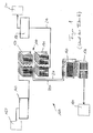
- FIG 1 is a schematic structure of such Data processing system 100 with distribution device 110 according to the state of the art.
- the Distribution device 110 two separate distribution blocks 120, 130 on, of which the distributor block 120 for exclusive Transmission of voice data signals with a switchgear 140 (e.g. a distribution block) of a telephone exchange system 150 and a splitter device 160 is connected, which in turn for the transfer of exclusively Computer data signals connected to a modem device 170 which is connected to a computer network 180.
- the second distributor block 130 of the distributor device 110 is for the transfer of both computer and Voice data signals with switchgear 190 (e.g. one Distribution block) of a subscriber 200 and the Splitter device 160 connected.
- Telecommunications systems are outgoing from subscriber 200 Computer and voice data signals on a common line 210 transmitted to and from the second distributor block 130 via a distributor line 220 to the splitter device 160 forwarded.
- the Computer data signals are forwarded to the modem device 170 and the voice data signals to the first distribution block 120 are forwarded, from which they then the Telephone switching system 150 are supplied.
- the Telephone switching system 150 In reverse Traps are from the telephone switching system 150 through the first distribution block 120 incoming voice data signals as well those arriving from the computer network via the modem 170 Computer data signals from the splitter device 160 merged and via the second distributor block 130 to the Participants 200 passed on.
- Telecommunication system 100 are connecting lines 220, 230 with associated connections both between the first Manifold block 120 and splitter device 160 as well between the second manifold block 130 and the Splitter device 160 required.
- a distribution device in particular a Main distributor, a data signal processing system provided with a distributor block
- the functional elements has to be connected to the data signal lines can and an interconnection for the distribution of the Data signal lines transmitted to the distribution device Have data signals.
- the distributor block also has one Recording device in which the functional elements are included.
- the distribution device has one Data signal processing unit with active and / or passive electronic components, of which those of the Data signal lines transmitted data signals in be prepared in a predetermined manner. This data signal processing unit is in the components of the distribution block integrated.
- Passive electronic components include components such as for example resistors, capacitors, coils and the like to understand whereas active electronic components than all Types of semiconductor elements, such as transistors, are to be understood.
- the Data signals which are both analog and digital Voice data and computer data signals can be in processed as desired, e.g. divided, goal-oriented assigned or organized as well as combined again Total voice data / computer data signal are merged, to get a large number of at the same time Signal lines of participants transmitted voice and Forward computer data signals in a targeted manner.
- the distribution device provides physical a component with sufficiently large premises as well related problem-free expansion options for Housing additional components so that the Attachment of the electronic components of the data signal processing unit on the hardware parts, i.e. Components, the distributor in a simple manner and therefore is inexpensive to implement.
- the distribution device thus provides through the integral Formation of the distribution block with the data signal processing unit and the short achieved thereby Interconnection and cable routes and reduced number of electrical contact points a powerful yet less susceptible to failure for use in one Data signal processing system.
- Distribution device is also a secure separation from respective participants achieved because the Distribution and thus breakdown of their data signals secure access within those not accessible to third parties Distribution device takes place.
- the distribution device according to the invention can be used for connection be provided by copper lines connected to associated Cable clamps, preferably insulation displacement clamps, are attached, which in turn with the formation of one or more Terminal strip (s) in one or more row (s) on the respective functional element are arranged.
- the functional elements can also accommodate Coaxial cables and fiber optic cables can be formed.
- the distribution device is as Hybrid distributor designed to accommodate the functional elements of all three types of cable mentioned, i.e. Copper, coaxial and Fiber optic cable.
- the Data signal processing unit a filter arrangement High and / or low and / or bandpass filters, from which the data signals transmitted by the data signal lines in accordance with whose frequency ranges can be filtered out and forwarded.
- the filter arrangement will be on one Data signal line simultaneously transmitted data signals, such as Voice data and computer data signals, depending on their filtered specific frequency ranges and to associated Distribution lines forwarded, e.g. to a Modem device with subsequent computer network or too a telephone switching system.
- This can be a Data transfer of different data signals between the Distribution device and connected participants via a common one assigned to the respective participant Data signal line done.
- the different Data signals are different here Data signal frequencies assigned by the filter arrangement are captured to the associated data signals filter and according to the respective participant as well the type of data signal (voice data signal or computer data signals) to be able to forward them in a targeted manner.
- the electronic components of the data signal processing unit for example via separate brackets can be attached within the cradle she prefers directly on one or more of the Functional elements and / or on the receiving device arranged. This happens, for example, by the fact that Components directly on wall elements of the mounting device attached, e.g. riveted or screwed, or on Board elements of the functional elements are also soldered on. This will make it more space-saving and less expensive Construction achieved by the existing per se Components of the distributor block for mounting the additional components can be used. This poses represents a maximally integrative structure.
- the distributor block can also have one or more Have cassette elements or connector elements that with associated functional elements for mutual transmission are releasably assembled from data signals and in which the Data signal processing unit or a part thereof is. It is possible by simply changing the Cassette elements or connector elements with the distribution block retrofit current data signal processing units without having to replace the distributor as a whole or complex and thus perform expensive work, such as soldering to have to.
- the respective cassette element and the associated one Functional elements are preferred over a simple one Plug connection attached to each other, which at the same time as Interface between the cartridge element and the Functional element is formed.
- cassette elements or Connector elements as the location of the components of the It is the data signal processing unit in the distribution block particularly preferably the respective cassette element or Form connector element so that it is in exchange for an overvoltage / overcurrent protection magazine or one Overvoltage / overcurrent protective plug as well as using whose interface is connected to the functional element can be.
- protective magazines and protective plugs are on various embodiments of main distributors or Distribution strips provided according to the prior art. you Replacement by the cassette elements according to the invention or Plug elements therefore represents a particularly simple and space-saving embodiment, in which little additional structural changes made to the distributor construction Need to become. With the cassette element according to the invention or the connector element can thus also certain existing To be retrofitted.
- Receiving device in the form of a receiving trough, in which the functional elements can be inserted, the electronic components of the data signal processing unit or a part number of components on the bottom of the tub are attached, and being at least on the bottom of the tub a connector part is attached to the bottom of the Receptacle attached electronic components of the Data signal processing unit is connected and in that an associated functional element producing a electrical contact between the functional element and the am Components of the data signal processing unit attached to the bottom of the receiving trough can intervene.
- the receptacle forms with its closed on three sides Form a secure housing, which also from its open Page in a simple and variable way with the insertable functional elements can be equipped.
- the present large floor area of the tub represents one very sheltered yet easily accessible place for the Housing electronic components, because the Bottom surface is through the associated bottom wall of the Receptacle and to the front through the attached Functional elements protected; it is also simple Unplug the functional elements quickly to reveal.
- the Connector installed on the floor pan is also a secure electrical functional connection in a simple manner between the data signal processing unit and the Functional elements achieved.
- the electronic components for example, directly on the Trough bottom can be attached, they are preferred a circuit board attached to the bottom of the receptacle arranged.
- This board is also known as a backplane and has the advantage that the associated data signal processing unit as part of the receptacle can be assembled and replaced by the same, so that the associated distribution device is easily assembled and can be serviced.
- the electronic components are the Data signal processing unit or a part number of Components arranged on one or more carrier boards, the detachable with the respective functional element is / are assembled.
- the carrier board is for Example directly on the back of the functional element attached to the extension and electrically with the Functional element connected.
- the electronic ones Components of the data signal processing unit or a Number of parts of the components on one or more arranged between board / s, each between two Functional elements is / are and which with a Contacting device is / are. Are about the latter the electronic components on the intermediate board with the Connection of the distribution device connected.
- the functional elements advantageously on printed circuit boards, which are used to hold the electronic components of the Data signal processing unit are provided and on which Connections for connecting the data signal lines attached are.
- the printed circuit boards provide components with low Dimensions and high security in terms of transmission electrical signals. You can also as immediate bearer of connectors for the signal lines to be connected are provided, so that a further space saving and a simpler and thus cost-effective construction is achieved.
- insulation displacement terminals are preferably provided as connecting parts.
- coaxial and / or Optical fiber cables can be associated with the printed circuit boards Connector installed, e.g. screwed.
- the invention is also a data signal processing system with the invention Distribution device provided.
- This data / data signal processing system poses according to those described above Advantages of the distribution device a powerful and interference-free system with which voice data and Computer data signals even over long transmission distances can be transferred quickly and safely.
- a cassette element is according to the invention provided, which is a data signal processing unit active and / or passive electronic components, from a distribution device of a data signal processing system supplied data signals in predetermined Be prepared in a way.
- the cassette element according to the invention is designed so that it has an interface, on an associated functional element of Distribution device is arranged for mutual Transmission of data signals on the functional element can be attached.
- the cassette elements according to the invention can be done in a simple manner by way of data signal processing unit arranged in them replace updated cassette elements.
- the cassette element is preferably designed such that it in exchange for an overvoltage / overcurrent protection magazine as well as using its interface at a associated functional element of the distribution device for mutual transmission of data signals connected can be.
- existing distribution facilities e.g. certain Main distributor of telecommunications systems
- one Data signal processing unit can be retrofitted, whereby existing communication systems to simpler and more robust Systems are convertible.
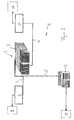
- Telecommunication system 1 has a distribution device 2 with a single distributor block 3, on which via lines 4, 5 and 6 a switchgear 7 (e.g. a distribution block) a telephone switching system 8, a modem device 9 of a computer network 10 or a switchgear 11 (e.g. a Distribution block) of a subscriber 12 are connected.
- a switchgear 7 e.g. a distribution block
- a telephone switching system 8 e.g. a telephone switching system 8
- modem device 9 of a computer network 10 or a switchgear 11 e.g. a Distribution block
- a switchgear 11 e.g. a Distribution block
- Via line 4 are between the distributor block 3 and the Telephone switching system only low-frequency Voice data signals are transmitted, whereas via line 5 only computer data signals, especially with high frequencies, between the computer network 10 - with the interposition of the Modem device 9 - and the distribution block 3 of Distribution device 2 are transmitted. Via line 6 become voice data signals and computer data signals at the same time between subscriber 12 and distribution block 3 transmitted.
- the distributor block 3 is a not shown Integrated data signal processing unit, of which the Voice data signals and the computer data signals, which over the Lines 4 and 5 are fed to the distributor block 3 a combined voice data / computer data signal are merged, which then via line 6 to the Participant 12 is fed. Conversely, one of the participants 12 via the line 6 to the distributor block 3 Combined voice data / computer data signal from the in the Distribution block integrated data signal processing unit in separate voice data signals and computer data signals divided and via the respective associated lines 4 and 5 to the Telephone switching system 8 or the computer network 10 forwarded.
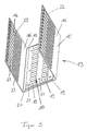
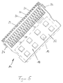
- FIGS. 3 and 4 show an elongated receptacle 13 a distribution block 3 of a data signal processing system according to an embodiment of the invention in two different perspective views; the Distribution block 3 is in this case as the main distributor intended.
- Receiving tray 1 are functional elements 14 as they shown for example using an example in Figure 3 are, with their longitudinal direction transverse to the longitudinal direction of the Receiving tray 13 inserted one above the other, whereby the Distribution block 3 is formed, by means of which the signals of lines connected to the distributor in a predetermined Way to be distributed.
- the receiving trough 13 has a continuously U-shaped Cross section and thus two mutually parallel side walls as Tub legs 15, 16 and one to these tub legs 15, 16 vertical trough bottom 17, over which the Tub legs 15, 16 are connected to each other.
- the Receiving tray 13 is preferably made of a sheet metal material manufactured, which is easy to bend and which is also good can be processed by punching.
- the way of making the in the tub-shaped recesses is not on Limited punching; there are other types of manufacture such as for example laser processing in question.
- a data signal processing unit 18 on the inside the receiving trough is a data signal processing unit 18 in the form of an arrangement of active and passive electronic Components 19, i.e. Resistors, coils and coils and the like or semiconductor elements in the form of transistors appropriate.
- the Data signal processing unit 18 From this data signal processing unit 18 the data signals and distributed by means of the distributor their associated data recorded, divided and goal-oriented, i.e. according to the intended data target and the type of data signal (Voice data signal or computer data signal) passed on.
- the Data signal processing unit 18 is so-called Splitter filter arrangement formed, from which a data / data signal bundle frequency-oriented data signals filtered out and sent to the corresponding send destinations to get redirected.
- These send destinations are with one preferred arrangement of the main distributor according to the invention in a telecommunication system the participants as well as a Telephone switching system and a computer network, by means of whose the desired mediation of the participants regarding whose voice and computer data is made possible with each other.
- the data signal processing unit 18 but also from the telephone exchange system Voice data signals and outgoing from the computer network Computer data signals for combined voice data / computer data signals merged, which then over a common line to the participants.
- the data signal processing unit 18 has a circuit board 20 Holes 21 through which the board 20 on the tub bottom 17 of the Receiving tray 13, for example by means of riveting or screwing is attached.
- the components 19 of the data signal processing unit 18 in turn are not associated with illustrated conductor tracks standing on the board 20 by means of Soldering or plug contacts attached.
- the tub legs 15, 16 each have a number of Holding tongues 22, which e.g. by punching from the Tub legs 15, 16 are formed and which also as Connection tongues for internal distribution cables can serve. Between the fixed end of the tabs 22 and the tub floor 17 is still a narrow one Leg section 15 ', 16' of the respective tub leg 15, 16 as a recess-free side wall section of the receiving trough 13 provided, which leg section 15 ', 16' the foot for the associated holding tongues 22 forms.
- the respective retaining tongue 22 has a hole-shaped recess at its free end section 23, in which a hook 24 of an associated functional element 14 (see Figure 5) can intervene to engage Define functional element 14 on the receiving trough 13.
- the respective retaining tongue 22 also points to its free End section of a recess 25 adjacent to the recess 23 on which to accommodate a wire guide, not shown is provided for connection wires.
- the recess 25 is for this purpose hook-shaped, so that the not shown Wire guide for its attachment to the retaining tongue 22 with a corresponding counterpart can engage in the recess 25.
- the recesses 23 of the holding tongues 22 of the in FIGS. 3 and 4 right and left tub legs 15, 16 are in the longitudinal direction the receptacle 13 seen in opposite directions Directions open to the side.
- the holding tongues 22 of the in Figures 3, 4 right tub legs 15 are on their free End sections further with an end recess 26 provided, whereas the free end portions of the retaining tongues 22 of the tub legs 16 on the left in FIGS. 3, 4 such Do not have recess.
- the front recesses 26 serve to accommodate the not shown guide lugs Functional elements 14, so that the latter when mounting the Distribution blocks only in the correct orientation in the Receiving tray 13 can be used.
- the holding tongues 22 are also at their other end section, i.e. their foot section, with one in the longitudinal direction of the tongue elongated recess 27 provided. These recesses 27 serve to accommodate the receptacle 13 from the side advanced cable connectors (not shown), which in turn in corresponding receptacles on the Functional elements 14 for the transmission of data signals are plugged in. There are cables for these cable connectors the interconnection of the functional elements 14 and / or Interconnections via printed circuit boards provided.
- the data signal conditioning unit 18 also a connector part 28 in Form of a socket in which an associated, as Plug-shaped connector part (not shown) one of the functional elements 14 can intervene so as to electrical contact between the functional element 14 and its internal interconnection as well as its existing one Interconnection with other functional elements in a simple way by inserting this functional element 14 into the To achieve receptacle 13.
- the functional element 14 shown in FIG. 5 is for Inclusion of copper cables or other stranded cables with a Terminal block 29 with a number of insulation displacement terminals 30 provided, into which the copper cables to be connected (not shown).
- the insulation displacement clamps 30 are successively arranged in a longitudinal row, whereby at the respective end of the terminal block 29 one of the above described hook 24 is located.
- the insulation displacement clamps 30 are continued downwards through contact springs 31, via which a plug contact with a not shown Distribution circuit is achieved.
- the functional element 14 also has a second terminal strip, not shown, which of the terminal block 29 described above is formed and is arranged parallel to this.
- the signal flow usually runs separately in the respective Functional elements 14, namely between the lines that the two cable strips belonging to the functional element 14 are connected.
- interconnections between Lines there are also interconnections between Lines conceivable that are connected to different functional elements 14 are connected.
- a functional element can do more than two cable strips.
- the interconnections are in Form of cable guides integrated in the main distributor performed; alternatively, printed circuit boards are also included corresponding conductor tracks are provided as interconnections.
- the terminal block 29 and the terminal block, not shown, are attached to a printed circuit board 32 on which components 19 a data signal processing unit 18 are attached.
- the Printed circuit board can also be used on both sides with such components be provided, thereby saving space.
- the Arrangement of the data signal processing unit 18 on Functional element 14 has the advantage that it is specific to the associated circuit diagram of the functional element 14 can be adjusted and thus anywhere in any receiving trays 13 can be arranged without additional coordination between processing unit 18 and Functional element 14 must be made.
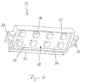
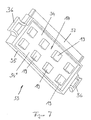
- Figures 6 and 7 show a cassette element according to the invention 33 a distribution device of a data signal processing system according to an embodiment of the invention in two different perspective views.
- the cassette element 33 has a printed circuit board 34, on the two sides of which, ie on the front 34 'and the rear 34 '', components 19 of a data signal processing unit 18 as described above are attached.
- the printed circuit board 34 is enclosed by a frame 35, on which two handles 36 are attached, which are arranged on mutually opposite frame sections.
- the cassette element 33 is rectangular, the handles 36 being arranged on the shorter rectangular sides of the frame 35.
- a contact spring strip 37 which is in electrical connection with the components 19 of the data signal processing system 18 arranged on the printed circuit board 32 and which can be plugged into an associated receptacle (not shown) on an associated functional element 14, in order to establish an electrical connection between the data signal processing unit 18 on the cassette side and the circuitry and / or the data signal processing unit 18 of the functional element 14 and / or the data signal processing unit in the receiving trough 13 in which the functional element 14 is accommodated.
- the contact spring strip 37 is particularly preferred Cassette element 33 to such a functional element Connection socket designed compatible, the otherwise for Inclusion of overvoltage / overcurrent protection magazines is provided. This can be done in the event that it is the default Protection regulations allow the protection magazine one Distributor, e.g. a main distributor one Telecommunication system, under formation of a distribution device according to the invention by the cassette element according to the invention with data signal processing unit 18 are replaced, making the associated Data signal processing system to a faster and nevertheless safe working system can be upgraded.
- a main distributor one Telecommunication system under formation of a distribution device according to the invention by the cassette element according to the invention with data signal processing unit 18 are replaced, making the associated Data signal processing system to a faster and nevertheless safe working system can be upgraded.
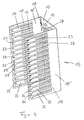
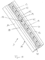
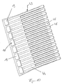
- FIG 8 is a distributor block 3 in the form of a elongated manifold 38 according to one embodiment presented the invention.
- the distributor bar 38 has Cross section of an E-profile, the two outer ones Groin legs 39, 40 of the distribution bar 38 the Form functional elements 14 to those not shown Signal lines are connected.
- the Groin legs 39, 40 on their back cable clamps on to which the signal lines can be attached.
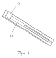
- a middle leg 41 of the E-profiled distribution strip 38 is on its front with recesses for receiving Individual plugs 42 are provided, on which in turn components 19 a data signal processing unit 18 are attached.
- the Single plugs 42 are exchanged for overcurrent / overvoltage protection plugs included in the recesses.
- the components 19 of the Data signal processing unit 18 also by others Fastening types must be attached to the distribution strip, e.g. by screwing on the middle leg 41.
- FIG. 9 shows an individual plug 42 according to the invention with a Component 19 of a data signal processing unit shown.
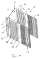
- FIG. 10 shows an alternative to the individual plugs 42 visible; hereafter a plug cassette 43 is provided, which has a circuit board 44, from the connecting tongues 45 are formed, which are in electrical contact with the Distribution board 38 can be brought by the Plug cassette 43 with its connecting tongues in the Recesses of the distributor bar 38 is inserted.
- a plug cassette 43 which has a circuit board 44, from the connecting tongues 45 are formed, which are in electrical contact with the Distribution board 38 can be brought by the Plug cassette 43 with its connecting tongues in the Recesses of the distributor bar 38 is inserted.
- On the Board 44 are also components 19 of a data signal processing unit 18 attached.
- FIG Main distributor Another receiving trough 13 is shown in FIG Main distributor according to an embodiment of the invention shown.
- This receptacle 13 differs from that in Figure 3 and 4 receiving tray 13 in that they longer tub legs 15, 16, each two Have leg regions 46, 47, namely one Trough bottom 17 adjacent leg area 46 and one Leg area 47 facing away from the tub floor. The latter are closed the tub legs 15, 16 of those described in Figures 3, 4 Receiving tray essentially identical, so that their description is omitted.
- the leg regions 46 of the tub floor 17 facing the Tub legs 15, 16 each have elongated Recesses 48 which extend with their longitudinal direction in those Extend in the direction in which the respective tub leg 15, 16 extends away from the tub floor 17.
- the recesses 48 serve to accommodate cassette elements 33, which are of the Side of the receptacle 13 in the recesses 48th are insertable and then in the front area arranged between the leg regions 47 Functional elements 14 producing an electrical Connection can be inserted.
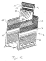
- Figures 12 and 13 show assembly operations when assembling a main distributor according to the invention as distributor block 3 one Distribution device 2.
- the main distributor has one Receiving trough 13 according to the type described with reference to FIG. 11, so that with regard to the construction of the receptacle 13 on the above Explanations are referenced.
- FIG. 13 shows how a cassette element 33 from the side of the receptacle 13 forth in the associated recess 48 is insertable.
- the cassette elements 33 are then of the Back of the functional elements 14 ago forming a electrical contact with the functional elements 14 plugged together.
- each functional element 14 has a data signal processing unit specially assigned to it having.
- FIG. 14 schematically shows a distributor device 2 a distribution block 3 in the form of a main distributor an embodiment of the invention.
- the distributor block 3 has a receptacle 13 with a U-profile, in the Tub legs 15, 16 slots 53 for receiving Functional elements 14 and arranged between them Intermediate boards 54 (only one is shown) are formed are.
- Intermediate boards 54 (only one is shown) are formed are on the respective intermediate board 54 .
- On the respective intermediate board 54 is one data signal processing unit assigned to the respective functional element 14 6 with electronic components 19 arranged.
- the circuit board 55 can also be used as a carrier board for receiving of electronic components of the or a data signal processing unit his; it is via a plug connector 56 electrically connected to a printed circuit board 20 (backplane), which is attached to the inside of the tub bottom 17.
- a printed circuit board 20 backplane
Landscapes
- Engineering & Computer Science (AREA)
- Computer Networks & Wireless Communication (AREA)
- Structure Of Telephone Exchanges (AREA)
- Communication Control (AREA)
- Radar Systems Or Details Thereof (AREA)
- Cable Transmission Systems, Equalization Of Radio And Reduction Of Echo (AREA)
- Arrangements For Transmission Of Measured Signals (AREA)
- Computer And Data Communications (AREA)
- Devices For Checking Fares Or Tickets At Control Points (AREA)
- Alarm Systems (AREA)
- Signal Processing For Digital Recording And Reproducing (AREA)
Abstract
Description
Die Erfindung betrifft eine Verteilereinrichtung, insbesondere einen Hauptverteiler, einer Datensignal-Verarbeitungsanlage, eine Datensignal-Verarbeitungsanlage sowie ein Kassettenelement für eine Verteilereinrichtung einer Datenverarbeitungsanlage.The invention relates to a distribution device, in particular a main distributor, a data signal processing system, a data signal processing system and a cassette element for a distribution device of a data processing system.
Verteilereinrichtungen werden zum Beispiel in Telekommunikationsanlagen eingesetzt, insbesondere dann, wenn eine größere Anzahl von Teilnehmern mit einer zugehörigen Vermittlungseinrichtung verbunden werden soll. Über die Telekommunikationsanlage findet hierbei neben dem Transfer von Sprachdaten von Telefongeräten auch verstärkt ein Transfer von Rechnerdaten statt.Distribution devices are for example in Telecommunications systems used, especially if a larger number of participants with an associated one Switching device is to be connected. About the Telecommunications system takes place in addition to the transfer of Voice data from telephone devices also increases the transfer of Computer data instead.
Um hierfür bereits bestehende Strukturen von Kupferkabelnetzen ausnutzen zu können, werden sowohl für die niedrigfrequenten Sprachsignale als auch für die höherfrequenten Rechnersignale gemeinsame Übertragungsleitungen verwendet. Um hierbei Rechnerdaten und Sprachdaten gleichzeitig über eine gemeinsame Leitung transferieren zu können, müssen die zugehörigen Signale sowohl auf der Kundenseite, als auch in einer Vermittlungsstelle zusammengeführt sowie nach der Übermittleungsstrecke wieder voneinander getrennt werden. Dies geschieht beispielsweise mit sogenannten Splittereinrichtungen, von denen die Sprach- und Rechnersignale gemäß deren unterschiedlichen Signalfrequenzen voneinander getrennt und der jeweiligen Verwendung zugeordnet werden. Das heißt, es erfolgt eine Aufbereitung von Datensignalen durch eine gezielte Aufteilung von Frequenzbereichen der zu übermittelnden Daten an jeweilige Sprachteilnehmer sowie die zur Verarbeitung der Daten vorgesehenen Einrichtungen.To do this already existing structures of copper cable networks To be able to exploit both low-frequency Speech signals as well as for the higher-frequency computer signals shared transmission lines. To do this Computer data and voice data at the same time via a common To be able to transfer line, the associated signals both on the customer side and in one Exchange merged and after the Transmission route are separated from each other again. This happens, for example, with so-called splinter devices, of which the voice and computer signals according to their different signal frequencies separated from each other and the assigned to each use. That is, it happens a preparation of data signals by a targeted Distribution of frequency ranges of the data to be transmitted respective language participants as well as those for processing the data provided facilities.
Solche Datenaufbereitungseinrichtungen sind bislang als additive Komponenten vorgesehen, die als externe Komponenten zu bestehenden Datensignal-Verarbeitungsanlagen hinzugefügt sind. Hierdurch ergeben sich Probleme dahingehend, dass solche Datenaufbereitungseinrichtungen mit langen Anschlusswegen und einer hohen Anzahl von elektronischen Kontaktelementen zur Herstellung der notwendigen Verbindungen zu der Datensignal-Verarbeitungsanlage einhergehen. Hierdurch wird die zugehörige Gesamtanlage insgesamt teurer und störanfälliger, wobei letzteres insbesondere bei langen Übertragungsstrecken der Fall ist. Hierbei müssen dann durch lange Leitungswege und viele Kontaktstellen verursachte Verluste in der Signalleistung durch aufwendige und wiederum teure Verstärkungs- und Entstörungsmaßnahmen beseitigt werden.Such data processing devices are so far as additive components provided as external components too existing data signal processing systems are added. This creates problems in that such Data processing devices with long connection paths and a large number of electronic contact elements for Establishing the necessary connections to the data signal processing system accompanied. This will make the associated one Overall system overall more expensive and prone to failure, whereby the latter is particularly the case with long transmission distances is. In this case, they have to go through long lines and many Contact points caused losses in the signal power complex and again expensive reinforcement and Interference suppression measures are eliminated.
In Figur 1 ist ein schematischer Aufbau einer solchen
Datenverarbeitungsanlage 100 mit Verteilereinrichtung 110 gemäß
dem Stand der Technik dargestellt. Hiernach weist die
Verteilereinrichtung 110 zwei separate Verteilerblöcke 120, 130
auf, von denen der Verteilerblock 120 zur ausschließlichen
Übertragung von Sprachdatensignalen mit einer Schaltanlage 140
(z.B. einem Verteilerblock) eines Telefonvermittlungssystems
150 sowie einer Splittereinrichtung 160 verbunden ist, welche
ihrerseits zur Übertragung von ausschließlich
Rechnerdatensignalen mit einer Modemeinrichtung 170 verbunden
ist, welche mit einem Rechnernetzwerk 180 in Verbindung steht.
Der zweite Verteilerblock 130 der Verteilereinrichtung 110 ist
zur Übertragung von sowohl Rechner- als auch
Sprachdatensignalen mit der Schaltanlage 190 (z.B. einem
Verteilerblock) eines Teilnehmers 200 und der
Splittereinrichtung 160 verbunden. Bei dieser
Telekommunikationsanlage werden vom Teilnehmer 200 ausgehende
Rechner- und Sprachdatensignale auf einer gemeinsamen Leitung
210 zum zweiten Verteilerblock 130 übermittelt und von diesem
über eine Verteilerleitung 220 an die Splittereinrichtung 160
weitergeleitet. Von der Splittereinichtung 160 werden die
Sprach- und Rechnerdatensignale aufgetrennt, wobei die
Rechnerdatensignale an die Modemeinrichtung 170 weitergeleitet
werden und die Sprachdatensignale an den ersten Verteilerblock
120 weitergeleitet werden, von dem sie dann dem
Telefonvermittlungssystem 150 zugeführt werden. Im umgekehrten
Falle werden die vom Telefonvermittlungssystem 150 über den
ersten Verteilerblock 120 ankommenden Sprachdatensignale sowie
die vom Rechnernetzwerk über das Modem 170 ankommenden
Rechnerdatensignale von der Splittereinrichtung 160
zusammengeführt und über den zweiten Verteilerblock 130 an den
Teilnehmer 200 weitergegeben. Bei dieser
Telekommunikationsanlage 100 sind Verbindungsleitungen 220, 230
mit zugehörigen Anschlüssen sowohl zwischen dem ersten
Verteilerblock 120 und der Splittereinrichtung 160 als auch
zwischen dem zweiten Verteilerblock 130 und der
Splittereinrichtung 160 erforderlich.In Figure 1 is a schematic structure of such
Es ist eine Aufgabe der Erfindung, eine Einrichtung für eine Datensignal-Verarbeitungsanlage sowie eine Datensignal-Verarbeitungsanlage zu schaffen, bei welchen Sprachdaten- und Rechnerdatensignale über gemeinsame Leitungen übertragbar sind und mit welchen dennoch eine gute und störungssichere Datenübertragung auch bei langen Übertragungsstrecken ermöglicht ist. Es ist eine andere Aufgabe der Erfindung, ein Mittel bereitzustellen, mit dem eine bestehende Datensignal-Verarbeitungsanlage unter Ausbildung einer erfindungsgemäßen Anlage auf einfache Weise nachrüstbar ist.It is an object of the invention to provide a device for a Data signal processing system and a data signal processing system to create with which voice data and Computer data signals can be transmitted via common lines and with which nevertheless a good and fail-safe Data transmission even with long transmission distances is possible. It is another object of the invention to provide a Provide means with which an existing data signal processing system to form an inventive System can be easily retrofitted.
Erfindungsgemäß ist eine Verteilereinrichtung, insbesondere ein Hauptverteiler, einer Datensignal-Verarbeitungsanlage vorgesehen, mit einem Verteilerblock, der Funktionselemente aufweist, an die Datensignalleitungen angeschlossen werden können und die eine Verschaltung zur Verteilung der von den Datensignalleitungen an die Verteilereinrichtung übermittelten Datensignale aufweisen. Der Verteilerblock weist ferner eine Aufnahmevorrichtung auf, in welcher die Funktionselemente aufgenommen sind. Die Verteilereinrichtung hat eine Datensignal-Aufbereitungseinheit mit aktiven und/oder passiven elektronischen Bauteilen, von der die von den Datensignalleitungen übermittelten Datensignale in vorbestimmter Weise aufbereitet werden. Diese Datensignal-Aufbereitungseinheit ist in die Komponenten des Verteilerblocks integriert. According to the invention, a distribution device, in particular a Main distributor, a data signal processing system provided with a distributor block, the functional elements has to be connected to the data signal lines can and an interconnection for the distribution of the Data signal lines transmitted to the distribution device Have data signals. The distributor block also has one Recording device in which the functional elements are included. The distribution device has one Data signal processing unit with active and / or passive electronic components, of which those of the Data signal lines transmitted data signals in be prepared in a predetermined manner. This data signal processing unit is in the components of the distribution block integrated.
Unter passiven elektronischen Bauteilen sind hier Bauteile, wie zum Beispiel Widerstände, Kondensatoren, Spulen und dergleichen zu verstehen, wohingegen aktive elektronische Bauteile als alle Arten von Halbleiterelementen, wie zum Beispiel Transistoren, zu verstehen sind.Passive electronic components include components such as for example resistors, capacitors, coils and the like to understand whereas active electronic components than all Types of semiconductor elements, such as transistors, are to be understood.
Mittels der Datensignal-Aufbereitungseinheit können die Datensignale, welche sowohl analoge als auch digitale Sprachdaten- und Rechnerdatensignale sein können, in gewünschter Weise aufbereitet, z.B. aufgeteilt, zielorientiert zugeordnet oder organisiert sowie wieder zu einem kombinierten Sprachdaten-/Rechnerdaten-Gesamtsignal zusammengeführt werden, um somit eine große Anzahl an gleichzeitig über die Signalleitungen von Teilnehmern übermittelten Sprach- und Rechnerdatensignale zielgerecht weiterzuleiten.By means of the data signal processing unit, the Data signals, which are both analog and digital Voice data and computer data signals can be in processed as desired, e.g. divided, goal-oriented assigned or organized as well as combined again Total voice data / computer data signal are merged, to get a large number of at the same time Signal lines of participants transmitted voice and Forward computer data signals in a targeted manner.
Mittels der Integration dieser Datensignal-Aufbereitungseinheit in die Verteilereinrichtung kann hierbei eine starke Vereinfachung des Aufbaus einer zugehörigen Telekommunikationsanlage erreicht werden. So können die von Telefonvermittlungssystemen und Netzwerken ausgehenden Datensignale unmittelbar, d.h. ohne Zwischenschaltung weiterer Verteiler- oder Aufbereitungssysteme, an die Verteilereinrichtung geleitet werden, da die Aufbereitung der Datensignale von der in die Verteilereinrichtung integrierten Datensignal-Aufbereitungseinheit durchgeführt wird. Ferner entfallen durch die integrale Ausbildung der Verteilereinrichtung mit der Datensignal-Aufbereitungseinheit lange Übertragungsleitungen zwischen Verteilerblöcken und Datensignal-Aufbereitungseinheit; insbesondere weist die Verteilereinrichtung eine reduzierte Anzahl an Leitungen und an zugehörigen Anschlüssen auf, da sowohl von den Teilnehmern als auch vom Netzwerk und einem Telefonvermittlungssystem Leitungen unmittelbar an den verteilerblock der Verteilereinrichtung herangeführt werden können, ohne dass irgendwelche Umleitungen zu anderen Verteilerblöcken und Aufbereitungsanlagen notwendig sind. Damit wird eine insgesamt einfachere und damit auch erheblich kostengünstigere und schneller installierbare Anlage bereitgestellt. Auch der Platzbedarf der Anlage ist mit dem Wegfall von Leitungen sowie mit der Verkürzung von Leitungswegen verringert.By integrating this data signal processing unit a strong one can be in the distribution device Simplifying the construction of an associated one Telecommunications system can be achieved. So those of Switching systems and networks outgoing Data signals immediately, i.e. without the interposition of others Distribution or processing systems to which Distribution device can be managed because the preparation of the Data signals from the integrated in the distribution device Data signal processing unit is performed. Further eliminated through the integral training of Distribution device with the data signal processing unit long transmission lines between distribution blocks and Data signal preprocessing unit; in particular, the Distribution device a reduced number of lines and on associated connections, since both from the participants as also from the network and a telephone switching system lines directly to the distributor block of the distributor device can be introduced without any diversions to other distribution blocks and processing plants necessary are. This will make it overall simpler and therefore easier considerably cheaper and quicker to install provided. The space requirement of the system is also with the Elimination of lines and the shortening of Line routes reduced.
Mit den kürzeren Leitungswegen und der geringeren Anzahl an zusätzlichen elektrischen Kontaktstellen für zusätzliche elektrische Verbindungen werden ferner auch die Leistungsfähigkeit der Anlage erhöht sowie deren Störanfälligkeit verringert.With the shorter cable routes and the smaller number of additional electrical contact points for additional electrical connections are also the Performance of the system increases as well Reduced susceptibility to faults.
Die Verteilereinrichtung stellt ihrerseits körperlich gesehen ein Bauteil mit ausreichend großen Räumlichkeiten sowie diesbezüglichen problemlosen Erweiterungsmöglichkeiten zur Unterbringung von zusätzlichen Bauteilen dar, so dass die Anbringung der elektronischen Bauteile der Datensignal-Aufbereitungseinheit an den Hardwareteilen, d.h. Baukomponenten, des Verteilers in einfacher Weise und damit kostengünstig realisierbar ist.For its part, the distribution device provides physical a component with sufficiently large premises as well related problem-free expansion options for Housing additional components so that the Attachment of the electronic components of the data signal processing unit on the hardware parts, i.e. Components, the distributor in a simple manner and therefore is inexpensive to implement.
Die Verteilereinrichtung stellt somit durch die integrale Ausbildung des Verteilerblocks mit der Datensignal-Aufbereitungseinheit und die dadurch erreichten kurzen Verschaltungs- und Leitungswege und verringerte Anzahl an elektrischen Kontaktstellen ein leistungsstarkes und dennoch wenig störanfälliges System für den Einsatz in einer Datensignal-Verarbeitungsanlage dar.The distribution device thus provides through the integral Formation of the distribution block with the data signal processing unit and the short achieved thereby Interconnection and cable routes and reduced number of electrical contact points a powerful yet less susceptible to failure for use in one Data signal processing system.
Mit der erfindungsgemäßen Verteilereinrichtung wird ferner eine sichere Abtrennung von jeweiligen Teilnehmern erreicht, da die Aufteilung und damit Aufschlüsselung deren Datensignale zugriffssicher innerhalb der für Dritte nicht zugänglichen Verteilereinrichtung erfolgt.With the distribution device according to the invention is also a secure separation from respective participants achieved because the Distribution and thus breakdown of their data signals secure access within those not accessible to third parties Distribution device takes place.
Die erfindungsgemäße Verteilereinrichtung kann zum Anschluss von Kupferleitungen vorgesehen sein, die an zugehörigen Kabelklemmen, bevorzugt Schneidklemmen, befestigt werden, welche ihrerseits unter Ausbildung einer oder mehrerer Klemmleiste(n) in einer oder mehreren Reihe(n) an dem jeweiligen Funktionselement angeordnet sind. Alternativ dazu können die Funktionselemente auch zur Aufnahme von Koaxialkabeln und Lichtwellenleiterkabeln ausgebildet sein. Nach einer Ausführung ist die Verteilereinrichtung als Hybridverteiler ausgebildet, der Funktionselemente zur Aufnahme von allen drei genannten Leitungsarten, d.h. Kupfer-, Koaxialund Lichtleiter-Kabel, hat.The distribution device according to the invention can be used for connection be provided by copper lines connected to associated Cable clamps, preferably insulation displacement clamps, are attached, which in turn with the formation of one or more Terminal strip (s) in one or more row (s) on the respective functional element are arranged. Alternatively the functional elements can also accommodate Coaxial cables and fiber optic cables can be formed. According to one version, the distribution device is as Hybrid distributor designed to accommodate the functional elements of all three types of cable mentioned, i.e. Copper, coaxial and Fiber optic cable.
Gemäß einer bevorzugten Ausführungsform der Erfindung weist die Datensignal-Aufbereitungseinheit eine Filter-Anordnung aus Hoch- und/oder Tief- und/oder Bandpassfiltern auf, von der die von den Datensignalleitungen übermittelten Datensignale gemäß deren Frequenzbereichen ausfilterbar und weiterleitbar ist.According to a preferred embodiment of the invention, the Data signal processing unit a filter arrangement High and / or low and / or bandpass filters, from which the data signals transmitted by the data signal lines in accordance with whose frequency ranges can be filtered out and forwarded.
Das heißt, von der Filter-Anordnung werden die auf einer Datensignalleitung gleichzeitig übermittelten Datensignale, wie Sprachdaten- und Rechnerdatensignale, je nach deren spezifischen Frequenzbereichen ausgefiltert und an zugehörige Verteilerleitungen weitergeleitet, die z.B. zu einer Modemeinrichtung mit nachfolgendem Rechnernetzwerk oder zu einem Telefonvermittlungssystem führen. Hierdurch kann ein Datentransfer von unterschiedlichen Datensignalen zwischen der Verteilereinrichtung und daran angeschlossenen Teilnehmern über eine gemeinsame, dem jeweiligen Teilnehmer zugeordnete Datensignalleitung erfolgen. Den unterschiedlichen Datensignalen sind hierbei unterschiedliche Datensignalfrequenzen zugeordnet, welche von der Filter-Anordnung erfasst werden, um die zugehörigen Datensignale auszufiltern und entsprechend dem jeweiligen Teilnehmer sowie der Datensignalart (Sprachdatensignal oder Rechnerdatensignale) gezielt weiterleiten zu können.That means that the filter arrangement will be on one Data signal line simultaneously transmitted data signals, such as Voice data and computer data signals, depending on their filtered specific frequency ranges and to associated Distribution lines forwarded, e.g. to a Modem device with subsequent computer network or too a telephone switching system. This can be a Data transfer of different data signals between the Distribution device and connected participants via a common one assigned to the respective participant Data signal line done. The different Data signals are different here Data signal frequencies assigned by the filter arrangement are captured to the associated data signals filter and according to the respective participant as well the type of data signal (voice data signal or computer data signals) to be able to forward them in a targeted manner.
Obwohl die elektronischen Bauteile der Datensignal-Aufbereitungseinheit beispielsweise über separate Halterungen innerhalb der Aufnahmevorrichtung angebracht sein können, sind sie bevorzugt unmittelbar an einem oder mehreren der Funktionselemente und/oder an der Aufnahmevorrichtung angeordnet. Dies geschieht zum Beispiel dadurch, dass die Bauteile direkt an Wandelementen der Aufnahmevorrichtung befestigt, z.B. genietet oder geschraubt, oder auf Platinenelemente der Funktionselemente mitaufgelötet werden. Hierdurch wird eine platzsparendere und kostengünstigere Konstruktion erreicht, indem die per se vorhandenen Bestandteile des Verteilerblocks unmittelbar zur Anbringung der zusätzlichen Bauteile ausgenutzt werden. Dies stellt damit einen maximal integrativen Aufbau dar.Although the electronic components of the data signal processing unit for example via separate brackets can be attached within the cradle she prefers directly on one or more of the Functional elements and / or on the receiving device arranged. This happens, for example, by the fact that Components directly on wall elements of the mounting device attached, e.g. riveted or screwed, or on Board elements of the functional elements are also soldered on. This will make it more space-saving and less expensive Construction achieved by the existing per se Components of the distributor block for mounting the additional components can be used. This poses represents a maximally integrative structure.
Alternativ dazu kann der Verteilerblock auch ein oder mehrere Kassettenelemente oder Steckerelemente aufweisen, die mit zugehörigen Funktionselementen zur gegenseitigen Übertragung von Datensignalen lösbar zusammengebaut sind und in welchen die Datensignal-Aufbereitungseinheit oder ein Teil davon angeordnet ist. Hierbei ist es möglich, durch einfaches Auswechseln der Kassettenelemente oder Steckerelemente den Verteilerblock mit aktuellen Datensignal-Aufbereitungseinheiten nachzurüsten, ohne den Verteiler insgesamt auswechseln zu müssen oder aufwendige und damit teure Arbeiten, wie zum Beispiel Löten, durchführen zu müssen. Das jeweilige Kassettenelement und das zugehörige Funktionselement sind bevorzugt über eine einfache Steckverbindung aneinander angebracht, die gleichzeitig als Schnittstelle zwischen dem Kassettenelement und dem Funktionselement ausgebildet ist.Alternatively, the distributor block can also have one or more Have cassette elements or connector elements that with associated functional elements for mutual transmission are releasably assembled from data signals and in which the Data signal processing unit or a part thereof is. It is possible by simply changing the Cassette elements or connector elements with the distribution block retrofit current data signal processing units without having to replace the distributor as a whole or complex and thus perform expensive work, such as soldering to have to. The respective cassette element and the associated one Functional elements are preferred over a simple one Plug connection attached to each other, which at the same time as Interface between the cartridge element and the Functional element is formed.
Im Falle der Verwendung von Kassettenelementen oder Steckerelementen als Unterbringungsort der Bauteile der Datensignal-Aufbereitungseinheit im Verteilerblock ist es besonders bevorzugt das jeweilige Kassettenelement oder Steckerelement derart auszubilden, dass es im Austausch gegen ein Überspannungs-/Überstromschutz-Magazin bzw. einen Überspannungs-/Überstrom-Schutzstecker sowie unter Verwendung deren Schnittstelle an das Funktionselement angeschlossen werden kann. Solche Schutzmagazine und Schutzstecker sind an diversen Ausführungsformen von Hauptverteilern bzw. Verteilerleisten gemäß dem Stand der Technik vorgesehen. Ihr Ersatz durch die erfindungsgemäßen Kassettenelemente bzw. Steckerelemente stellt daher eine besonders einfache und platzsparende Ausführungsform dar, bei der wenig zusätzliche bauliche Änderungen an der Verteilerkonstruktion vorgenommen werden müssen. Mit dem erfindungsgemäßen Kassettenelement bzw. dem Steckerelement können somit auch bestimmte bestehende Verteiler nachgerüstet werden.In case of using cassette elements or Connector elements as the location of the components of the It is the data signal processing unit in the distribution block particularly preferably the respective cassette element or Form connector element so that it is in exchange for an overvoltage / overcurrent protection magazine or one Overvoltage / overcurrent protective plug as well as using whose interface is connected to the functional element can be. Such protective magazines and protective plugs are on various embodiments of main distributors or Distribution strips provided according to the prior art. you Replacement by the cassette elements according to the invention or Plug elements therefore represents a particularly simple and space-saving embodiment, in which little additional structural changes made to the distributor construction Need to become. With the cassette element according to the invention or the connector element can thus also certain existing To be retrofitted.
Nach einer Ausführungsform der Erfindung ist die Aufnahmevorrichtung in Form einer Aufnahmewanne ausgebildet, in welche die Funktionselemente einsteckbar sind, wobei die elektronischen Bauteile der Datensignal-Aufbereitungseinheit oder ein Teilanzahl der Bauteile auf dem Boden der Wanne angebracht sind, und wobei auf dem Boden der Wanne wenigstens ein Steckverbinderteil angebracht ist, das an die am Boden der Aufnahmewanne angebrachten elektronischen Bauteile der Datensignal-Aufbereitungseinheit angeschlossen ist und in das ein zugehöriges Funktionselement unter Herstellung eines elektrischen Kontakts zwischen dem Funktionselement und den am Boden der Aufnahmewanne angebrachten Bauteilen der Datensignal-Aufbereitungseinheit eingreifen kann.According to one embodiment of the invention Receiving device in the form of a receiving trough, in which the functional elements can be inserted, the electronic components of the data signal processing unit or a part number of components on the bottom of the tub are attached, and being at least on the bottom of the tub a connector part is attached to the bottom of the Receptacle attached electronic components of the Data signal processing unit is connected and in that an associated functional element producing a electrical contact between the functional element and the am Components of the data signal processing unit attached to the bottom of the receiving trough can intervene.
Die Aufnahmewanne bildet mit ihrer dreiseitig geschlossenen Form eine sicheres Gehäuse, welches zudem von seiner offenen Seite her in einfacher und variabler Weise mit den einsteckbaren Funktionselementen bestückbar ist. Die vorliegende große Bodenfläche der Wanne stellt hierbei einen sehr geschützten und dennoch einfach zugänglichen Ort für die Unterbringung von elektronischen Bauteilen dar, denn die Bodenfläche ist rückseitig durch die zugehörige Bodenwand der Aufnahmewanne sowie nach vorne durch die aufgesteckten Funktionselemente geschützt; sie ist ferner durch einfaches Ausstecken der Funktionselemente schnell freizulegen. Durch den auf der Bodenwanne installierten Steckverbinder ist ebenfalls in einfacher Weise eine sichere elektrische Funktionsverbindung zwischen der Datensignal-Aufbereitungseinheit und den Funktionselementen erzielt.The receptacle forms with its closed on three sides Form a secure housing, which also from its open Page in a simple and variable way with the insertable functional elements can be equipped. The The present large floor area of the tub represents one very sheltered yet easily accessible place for the Housing electronic components, because the Bottom surface is through the associated bottom wall of the Receptacle and to the front through the attached Functional elements protected; it is also simple Unplug the functional elements quickly to reveal. By the Connector installed on the floor pan is also a secure electrical functional connection in a simple manner between the data signal processing unit and the Functional elements achieved.
Obwohl die elektronischen Bauteile beispielsweise direkt am Wannenboden angebracht sein können, sind sie bevorzugt auf einer am Boden der Aufnahmewanne angebrachten Platine angeordnet. Diese Platine wird auch als Backplane bezeichnet und hat den Vorteil, dass die zugehörige Datensignal-Aufbereitungseinheit als ein Teil an die Aufnahmewanne montierbar und von derselben auswechselbar ist, so dass die zugehörige Verteilereinrichtung einfacher zusammengebaut und gewartet werden kann.Although the electronic components, for example, directly on the Trough bottom can be attached, they are preferred a circuit board attached to the bottom of the receptacle arranged. This board is also known as a backplane and has the advantage that the associated data signal processing unit as part of the receptacle can be assembled and replaced by the same, so that the associated distribution device is easily assembled and can be serviced.
Alternativ oder zusätzlich sind die elektronischen Bauteile der Datensignal-Aufbereitungseinheit oder eine Teilanzahl der Bauteile auf einer oder mehreren Trägerplatine/n angeordnet, die lösbar mit dem jeweils zugehörigen Funktionselement zusammengebaut ist/sind. Die Trägerplatine ist hierbei zum Beispiel unmittelbar an der Hinterseite des Funktionselements unter Verlängerung desselben angebracht und elektrisch mit dem Funktionselement verbunden.Alternatively or additionally, the electronic components are the Data signal processing unit or a part number of Components arranged on one or more carrier boards, the detachable with the respective functional element is / are assembled. The carrier board is for Example directly on the back of the functional element attached to the extension and electrically with the Functional element connected.
Ferner alternativ oder zusätzlich sind die elektronischen Bauteile der Datensignal-Aufbereitungseinheit oder eine Teilanzahl der Bauteile auf einer oder mehreren zwischenplatine/n angeordnet, die je zwischen zwei Funktionselementen angeordnet ist/sind und welche mit einer Kontaktierungseinrichtung versehen ist/sind. Über letztere sind die elektronischen Bauteile auf der Zwischenplatine mit der Verschaltung der Verteilereinrichtung verbunden.Furthermore, alternatively or additionally, the electronic ones Components of the data signal processing unit or a Number of parts of the components on one or more arranged between board / s, each between two Functional elements is / are and which with a Contacting device is / are. Are about the latter the electronic components on the intermediate board with the Connection of the distribution device connected.
Im Falle der Verwendung der Funktionselemente als Aufnehmer der/von Bauteile/n der Datensignal-Aufbereitungseinheit weisen die Funktionselemente vorteilhafterweise Leiterplatinen auf, welche zur Aufnahme der elektronischen Bauteile der Datensignal-Aufbereitungseinheit vorgesehen sind und an welchen Anschlüsse zum Anschluss der Datensignalleitungen angebracht sind. Die Leiterplatinen stellen Bauteile mit geringen Abmessungen und hoher Sicherheit hinsichtlich der Übertragung elektrischer Signale dar. Sie können ferner auch als unmittelbare Träger von Anschlussteilen für die anzuschließenden Signalleitungen vorgesehen sein, so dass eine weitere Platzersparnis und ein einfacherer und damit kostengünstigerer Aufbau erzielt ist. Bei der Verwendung von Kupferkabeln oder dergleichen Litzenkabeln als Signalleitungen sind als Anschlussteile bevorzugt Schneidklemmen vorgesehen. Bei der Verwendung von Koaxial- und/oder Lichtwellenleiterkabeln können an die Leiterplatinen zugehörige Stecker montiert, z.B. geschraubt, sein.In the case of using the functional elements as sensors the / of components of the data signal processing unit the functional elements advantageously on printed circuit boards, which are used to hold the electronic components of the Data signal processing unit are provided and on which Connections for connecting the data signal lines attached are. The printed circuit boards provide components with low Dimensions and high security in terms of transmission electrical signals. You can also as immediate bearer of connectors for the signal lines to be connected are provided, so that a further space saving and a simpler and thus cost-effective construction is achieved. When using Copper cables or the like stranded cables as signal lines insulation displacement terminals are preferably provided as connecting parts. When using coaxial and / or Optical fiber cables can be associated with the printed circuit boards Connector installed, e.g. screwed.
Gemäß der Erfindung ist ferner eine Datensignal-Verarbeitungsanlage mit der erfindungsgemäßen Verteilereinrichtung vorgesehen. Diese Daten-/Datensignal-Verarbeitungsanlage stellt gemäß den oben beschriebenen Vorteilen der Verteilereinrichtung eine leistungsfähige und störungsfreie Anlage dar, mit welcher Sprachdaten- und Rechnerdatensignale auch über lange Übertragungsstrecken hinweg schnell und sicher übertragbar sind.According to the invention is also a data signal processing system with the invention Distribution device provided. This data / data signal processing system poses according to those described above Advantages of the distribution device a powerful and interference-free system with which voice data and Computer data signals even over long transmission distances can be transferred quickly and safely.
Des Weiteren ist erfindungsgemäß ein Kassettenelement vorgesehen, welches eine Datensignal-Aufbereitungseinheit aus aktiven und/oder passiven elektronischen Bauteilen aufweist, von der einer Verteilereinrichtung einer Datensignalverarbeitungsanlage zugeführte Datensignale in vorbestimmter Weise aufbereitet werden. Das erfindungsgemäße Kassettenelement ist derart ausgebildet ist, dass es über eine Schnittstelle, die an einem zugehörigen Funktionselement der Verteilereinrichtung angeordnet ist, zur gegenseitigen Übertragung von Datensignalen an dem Funktionselement angebracht werden kann. Die erfindungsgemäßen Kassettenelemente können in einfacher Weise durch hinichtlich der jeweils auf ihnen angeorneten Datensignal-Aufbereitungseinheit aktualisierte Kassettenelemente auswechseln.Furthermore, a cassette element is according to the invention provided, which is a data signal processing unit active and / or passive electronic components, from a distribution device of a data signal processing system supplied data signals in predetermined Be prepared in a way. The cassette element according to the invention is designed so that it has an interface, on an associated functional element of Distribution device is arranged for mutual Transmission of data signals on the functional element can be attached. The cassette elements according to the invention can be done in a simple manner by way of data signal processing unit arranged in them replace updated cassette elements.
Bevorzugt ist das Kassettenelement derart ausgebildet, dass es im Austausch gegen ein Überspannungs-/Überstromschutz-Magazin sowie unter Verwendung von dessen Schnittstelle an ein zugehöriges Funktionselement der Verteilereinrichtung zur gegenseitigen Übertragung von Datensignalen angeschlossen werden kann. Mit diesem erfindungsgemäßen Kassettenelement können bestehende Verteilereinrichtungen, wie z.B. bestimmte Hauptverteiler von Telekommunikationsanlagen, mit einer Datensignal-Aufbereitungseinheit nachgerüstet werden, wodurch bestehende Kommunikationssysteme zu einfacheren und robusteren Systemen umwandelbar sind.The cassette element is preferably designed such that it in exchange for an overvoltage / overcurrent protection magazine as well as using its interface at a associated functional element of the distribution device for mutual transmission of data signals connected can be. With this cassette element according to the invention existing distribution facilities, e.g. certain Main distributor of telecommunications systems, with one Data signal processing unit can be retrofitted, whereby existing communication systems to simpler and more robust Systems are convertible.
Die Erfindung wird im Folgenden anhand einer bevorzugten
Ausführungsform mit Bezugnahme auf die Zeichnung erläutert. In
der Zeichnung zeigen:
Die in Figur 2 gezeigte, erfindungsgemäße
Telekommunikationsanlage 1 weist eine Verteilereinrichtung 2
mit einem einzigen Verteilerblock 3 auf, an den über Leitungen
4, 5 und 6 eine Schaltanlage 7 (z.B. einem Verteilerblock)
eines Telefonvermittlungssystems 8, eine Modemeinrichtung 9
eines Rechnernetzwerks 10 bzw. eine Schaltanlage 11 (z.B. einem
Verteilerblock) eines Teilnehmers 12 angeschlossen sind. Im
Falle dass eine derart große Anzahl von Teilnehmern 6 an den
Verteilerblock angeschlossen ist, dass ein einziger
Verteilerblock 3 nicht ausreicht, können auch mehrere
gekoppelte Verteilerblöcke vorgesehen sein. Über die Leitung 4
werden zwischen dem Verteilerblock 3 und dem
Telefonvermittlungssystem nur niederfrequente
Sprachdatensignale übermittelt, wohingegen über die Leitung 5
nur Rechnerdatensignale, insbesondere mit hohen Frequenzen,
zwischen dem Rechnernetzwerk 10 - mit Zwischenschaltung der
Modemeinrichtung 9 - und dem Verteilerblock 3 der
Verteilereinrichtung 2 übermittelt werden. Über die Leitung 6
werden gleichzeitig Sprachdatensignale und Rechnerdatensignale
zwischen dem Teilnehmer 12 und dem Verteilerblock 3
übermittelt.The inventive shown in Figure 2
In den Verteilerblock 3 ist eine nicht dargestellte
Datensignal-Aufbereitungseinheit integriert, von der die
Sprachdatensignale und die Rechnerdatensignale, welche über die
Leitungen 4 bzw. 5 dem Veteilerblock 3 zugeführt werden, zu
einem kombinierten Sprachdaten-/Rechnerdatensignal
zusammengeführt werden, welches dann über die Leitung 6 dem
Teilnehmer 12 zugeführt wird. Umgekehrt wird ein vom Teilnehmer
12 über die Leitung 6 dem Verteilerblock 3 zugeführtes
kombiniertes Sprachdaten-/Rechnerdatensignal von der in den
Verteilerblock integrierten Datensignal-Aufbereitungseinheit in
separate Sprachdatensignale und Rechnerdatensignale aufgeteilt
und über die jeweils zugehörigen Leitungen 4 bzw. 5 an das
Telefonvermittlungssystem 8 bzw. das Rechnernetzwerk 10
weitergeleitet.In the
Bei der erfindungsgemäßen Telekommunikationsanlage 1 entfallen
demnach im Gegensatz zu der oben beschriebenen Anlage gemäß dem
Stand der Technik zwei Übertragungsleitungen mit zugehörigen
Anschlussteilen sowie ein separater Verteilerblock, der
zwischen das Modem und das Telefonvermittlungssystem geschaltet
ist.In the
Figuren 3 und 4 zeigen eine langgestreckte Aufnahmewanne 13
eines Verteilerblocks 3 einer Datensignal-Verarbeitungsanlage
gemäß einer Ausführungsform der Erfindung in zwei
unterschiedlichen perspektivischen Ansichten; der
Verteilerblock 3 ist in diesem Falle als Hauptverteiler
vorgesehen. In die aus Figuren 1 und 2 ersichtliche
Aufnahmewanne 1 werden Funktionselemente 14, wie sie
beispielsweise anhand eines Beispiels in Figur 3 dargestellt
sind, mit ihrer Längsrichtung quer zur Längsrichtung der
Aufnahmewanne 13 übereinanderliegend eingesteckt, wodurch der
Verteilerblock 3 ausgebildet wird, mittels dessen die Signale
von an den Verteiler angeschlossenen Leitungen in vorbestimmter
Weise verteilt werden.FIGS. 3 and 4 show an elongated receptacle 13
a
Die Aufnahmewanne 13 hat einen durchgehend U-förmigen
Querschnitt und damit zwei zueinander parallele Seitenwände als
Wannenschenkel 15, 16 und einen zu diesen Wannenschenkeln 15,
16 senkrecht verlaufenden Wannenboden 17, über den die
Wannenschenkel 15, 16 miteinander verbunden sind. Die
Aufnahmewanne 13 ist bevorzugt aus einem Blechmaterial
gefertigt, welches gut biegbar ist und welches sich ferner gut
per Stanzen bearbeiten lässt. Die Art der Herstellung der in
der Wanne ausgebildeten Ausnehmungen ist jedoch nicht auf
Stanzen beschränkt; es kommen auch andere Herstellungsarten wie
zum Beispiel eine Laserbearbeitung in Frage. An der Innenseite
der Aufnahmewanne ist eine Datensignal-Aufbereitungseinheit 18
in Form einer Anordnung aktiver und passiver elektronischer
Bauteile 19, d.h. Widerstände, Spulen und Spulen und
dergleichen bzw. Halbleiterelemente in Form von Transistoren
angebracht. Von dieser Datensignal-Aufbereitungseinheit 18
werden die mittels des Verteilers verteilten Datensignale und
deren zugehörige Daten erfasst, aufgeteilt und zielorientiert,
d.h. gemäß dem vorgesehenen Datenziel und der Datensignalart
(Sprachdatensignal oder Rechnerdatensignal) weitergeleitet. Die
Datensignal-Aufbereitungseinheit 18 ist damit als sogenannte
Splitterfilter-Anordnung ausgebildet, von der aus einem Daten/Datensignalbündel
frequenzorientiert Datensignale
herausgefiltert und an die zugehörigen Sendeziele
weitergeleitet werden. Diese Sendeziele sind bei einer
bevorzugten Anordnung des erfindungsgemäßen Hauptverteilers in
einer Telekommunikationsanlage die Teilnehmer sowie ein
Telefonvermittlungssystem und ein Rechnernetzwerk, mittels
deren die gewünschte Vermittlung der Teilnehmer hinsichtlich
deren Sprach- und Rechnerdaten untereinander ermöglicht wird.
Umgekehrt werden von der Datensignal-Aufbereitungseinheit 18
aber auch von dem Telefonvermittlungssystem ausgehende
Sprachdatensignale und von dem Rechnernetzwerk ausgehende
Rechnerdatensignale zu kombinierten Sprachdaten/Rechnerdatensignalen
zusammengeführt, welche dann über eine
gemeinsame Leitung den Teilnehmern zugeführt werden.The receiving
Die Datensignal-Aufbereitungseinheit 18 hat eine Platine 20 mit
Löchern 21, über welche die Platine 20 am Wannenboden 17 der
Aufnahmewanne 13 zum Beispiel mittels Nietens oder Schraubens
befestigt ist. Die Bauteile 19 der Datensignal-Aufbereitungseinheit
18 sind ihrerseits in Verbindung mit nicht
dargestellten Leiterbahnen stehend auf der Platine 20 mittels
Lötens oder Steckkontakten angebracht.The data
Die Wannenschenkel 15, 16 weisen jeweils eine Reihe von
Haltezungen 22 auf, welche z.B. mittels Stanzens aus den
Wannenschenkeln 15, 16 ausgeformt sind und welche auch als
Anschlusszungen für verteilerinterne Verschaltungsleitungen
dienen können. Zwischen dem festgelegten Ende der Haltezungen
22 und dem Wannenboden 17 ist noch ein schmaler
Schenkelabschnitt 15', 16' des jeweiligen Wannenschenkels 15,
16 als ausnehmungsfreier Seitenwandabschnitt der Aufnahmewanne
13 vorgesehen, welcher Schenkelabschnitt 15', 16' den Fuß für
die zugehörigen Haltezungen 22 bildet. Die jeweilige Haltezunge
22 hat an ihrem freien Endabschnitt eine lochförmige Ausnehmung
23, in welche ein Haken 24 eines zugehörigen Funktionselements
14 (siehe Figur 5) rastend eingreifen kann, um das
Funktionselement 14 an der Aufnahmewanne 13 festzulegen. Die
jeweilige Haltezunge 22 weist ferner an ihrem freien
Endabschnitt eine der Ausnehmung 23 benachbarte Aussparung 25
auf, welche zur Aufnahme einer nicht dargestellten Drahtführung
für Verschaltungsdrähte vorgesehen ist. Die Aussparung 25 ist
hierzu hakenförmig ausgebildet, so dass die nicht dargestellte
Drahführung zu ihrer Befestigung an der Haltezunge 22 mit einem
entsprechenden Gegenstück in die Aussparung 25 eingreifen kann.
Die Aussparungen 23 der Haltezungen 22 der in Figuren 3 und 4
rechten und linken Wannenschenkel 15, 16 sind in Längsrichtung
der Aufnahmewanne 13 gesehen in einander entgegengesetzten
Richtungen seitlich offen vorgesehen. Die Haltezungen 22 des in
Figuren 3, 4 rechten Wannenschenkels 15 sind an ihren freien
Endabschnitten ferner mit einer stirnseitigen Aussparung 26
versehen, wohingegen die freien Endabschnitte der Haltezungen
22 des in Figuren 3, 4 linken Wannenschenkel 16 eine solche
Aussparung nicht aufweisen. Die stirnseitigen Aussparungen 26
dienen der Aufnahme von nicht dargestellten Führungsnasen der
Funktionselemente 14, so dass letztere bei der Montage des
Verteilerblocks nur in richtiger Orientierung in die
Aufnahmewanne 13 einsetzbar sind.The
Die Haltezungen 22 sind ferner an ihrem anderen Endabschnitt,
d.h. ihrem Fußabschnitt, mit einer in Zungenlängsrichtung
langgestreckten Ausnehmung 27 versehen. Diese Ausnehmungen 27
dienen der Aufnahme von seitlich an die Aufnahmewanne 13
herangeführten Kabelsteckern (nicht dargestellt), welche
ihrerseits in entsprechende Aufnahmebuchsen an den
Funkionselementen 14 zur Übertragung von Datensignalen
eingesteckt sind. An diesen Kabelsteckern sind Leitungen für
die Verschaltung der Funktionselemente 14 und/oder
Verschaltungen via Leiterplatinen vorgesehen.The holding
Wie aus Figur 4 ersichtlich ist, weist die Datensignal-Aufbereitungseinheit
18 ferner ein Steckverbinderteil 28 in
Form einer Steckbuchse auf, in welches ein zugehöriges, als
Stecker ausgebildetes Steckverbinderteil (nicht dargestellt)
eines der Funktionselemente 14 eingreifen kann, um so einen
elektrischen Kontakt zwischen dem Funktionselement 14 und
dessen interner Verschaltung sowie dessen ggf. vorliegender
Verschaltung mit anderen Funktionselementen auf einfache Weise
durch Einstecken dieses Funktionselements 14 in die
Aufnahmewanne 13 zu erzielen.As can be seen from Figure 4, the data
Das aus Figur 5 ersichtliche Funktionselement 14 ist zur
Aufnahme von Kupferkabeln oder sonstigen Litzenkabeln mit einer
Klemmleiste 29 mit einer Anzahl von Schneidklemmen 30
vorgesehen, in welche die anzuschließenden Kupferkabel (nicht
dargestellt) eingesteckt werden. Die Schneidklemmen 30 sind
aufeinanderfolgend in einer Längsreihe angeordnet, wobei sich
am jeweiligen Stirnende der Klemmleiste 29 einer der oben
beschriebenen Haken 24 befindet. Die Schneidklemmen 30 sind
nach unten hin durch Kontaktfedern 31 fortgesetzt, über welche
ein Steckkontakt mit einer nicht dargestellten
Verteilungsschaltung erzielt wird. Das Funktionselement 14
weist ferner eine nicht dargestellte zweite Klemmleiste auf,
welche der oben beschriebenen Klemmleiste 29 entsprechend
ausgebildet ist und zu dieser parallel angeordnet ist. Der
Signalfluss verläuft in der Regel nur separat in den jeweiligen
Funktionselementen 14, und zwar zwischen den Leitungen, die an
die beiden zu dem Funktionselement 14 gehörigen Kabelleisten
angeschlossen sind. Es sind jedoch auch Verschaltungen zwischen
Leitungen denkbar, die an unterschiedliche Funktionselemente 14
angeschlossen sind. Ferner kann ein Funktionselement auch mehr
als zwei Kabelleisten aufweisen. Die Verschaltungen sind in
Form von in den Hauptverteiler integrierten Kabelführungen
ausgeführt; alternativ sind auch Leiterplatinen mit
entsprechenden Leiterbahnen als Verschaltungen vorgesehen.The
Die Klemmleiste 29 und die nicht dargestellte Klemmleiste sind
an einer Leiterplatine 32 angebracht, auf welcher Bauteile 19
einer Datensignal-Aufbereitungseinheit 18 angebracht sind. Die
Leiterplatine kann auch beidseitig mit derartigen Bauteilen
versehen sein, wodurch eine Platzersparnis erzielt wird. Die
Anordnung der Datensignal-Aufbereitungseinheit 18 am
Funktionselement 14 hat den Vorteil, dass sie speziell an den
zugehörigen Verschaltungsplan des Funktionselements 14
angepasst werden kann und damit an beliebiger Stelle in
beliebigen Aufnahmewannen 13 angeordnet werden kann, ohne dass
zusätzliche Abstimmungen zwischen Aufbereitungseinheit 18 und
Funktionselement 14 vorgenommen werden müssen.The
Figuren 6 und 7 zeigen ein erfindungsgemäßes Kassettenelement 33 einer Verteilereinrichtung einer Datensignal-Verarbeitungsanlage gemäß einer Ausführungsform der Erfindung in zwei unterschiedlichen perspektivischen Ansichten.Figures 6 and 7 show a cassette element according to the invention 33 a distribution device of a data signal processing system according to an embodiment of the invention in two different perspective views.
Das Kassettenelement 33 weist eine Leiterplatine 34 auf, auf
deren beiden Seiten, d.h. auf deren Vorderseite 34' und
Rückseite 34'', jeweils Bauteile 19 einer wie oben
beschriebenen Datensignal-Aufbereitungseinheit 18 angebracht
sind. Die Leiterplatine 34 ist von einem Rahmen 35 eingefasst,
an dem zwei Handgriffe 36 angebracht sind, die an einander
entgegengesetzten Rahmenabschnitten angeordnet sind. Das
Kassettenelement 33 ist rechteckig ausgebildet, wobei die
Handgriffe 36 an den kürzeren Rechteckseiten des Rahmens 35
angeordnet sind. An einer Längsseite des Kassettenelements 33
ist eine Kontaktfederleiste 37 vorgesehen, welche mit den auf
der Leiterplatine 32 angeordneten Bauteilen 19 der Datensignal-Aufbereitungsanlage
18 in elektrischer Verbindung steht und
welche in eine ihr zugeordnete Aufnahmebuchse (nicht
dargestellt) an einem zugehörigen Funktionselement 14
einsteckbar ist, um eine elektrische Verbindung zwischen der
kassettenseitigen Datensignal-Aufbereitungseinheit 18 und der
Verschaltung und/oder der Datensignal-Aufbereitungseinheit 18
des Funktionselements 14 und/oder der Datensignal-Aufbereitungseinheit
in der Aufnahmewanne 13, in welcher das
Funktionselement 14 aufgenommen ist, herzustellen.The
Besonders bevorzugt ist die Kontaktfederleiste 37 des
Kassettenelements 33 zu einer solchen funktionselementseitigen
Anschlussbuchse kompatibel ausgebildet, die ansonsten zur
Aufnahme von Überspannungs-/Überstrom-Schutzmagazinen
vorgesehen ist. Damit kann im Falle, dass es die vorgegeben
Schutzvorschriften erlauben, das Schutzmagazin einer
Verteilereinrichtung, z.B. eines Hauptverteilers einer
Telekommunikationsanlage, unter Ausbildung einer
erfindungsgemäßen Verteilereinrichtung durch das
erfindungsgemäße Kassettenelement mit Datensignal-Aufbereitungseinheit
18 ersetzt werden, wodurch die zugehörige
Datensignal-Verarbeitungsanlage zu einer schnelleren und
dennoch sicher arbeitenden Anlage aufrüstbar ist.The
In Figur 8 ist ein Verteilerblock 3 in Form einer
langgestreckten Verteilerleiste 38 gemäß einer Ausführungsform
der Erfindung dargestellt. Die Verteilerleiste 38 hat im
Querschnitt ein E-Profil, wobei die beiden äußeren
Leistenschenkel 39, 40 der Verteilerleiste 38 die
Funktionselememte 14 bilden, an die nicht dargestellte
Signalleitungen angeschlossen werden. Hierzu weisen die
Leistenschenkel 39, 40 an ihrer Rückseite Kabelklemmen auf, an
denen die Signalleitungen angebracht werden können.In Figure 8 is a
Ein mittlerer Schenkel 41 der E-profilierten Verteilerleiste 38
ist an seiner Vorderseite mit Ausnehmungen zur Aufnahme von
Einzelsteckern 42 versehen, an denen ihrerseits Bauteile 19
einer Datensignal-Aufbereitungseinheit 18 angebracht sind. Die
Einzelstecker 42 sind im Austausch gegen Überstrom/Überspannungs-Schutzstecker
in den Ausnehmungen aufgenommen.
Im Falle dass die verteilerleiste nicht mit derartigen
Schutzsteckern vorgesehen ist, können die Bauteile 19 der
Datensignal-Aufbereitungseinheit 18 auch durch andere
Befestigungsarten an der Verteilerleiste angebracht sein, z.B.
durch Anschrauben am mittleren Schenkel 41.A
In Figur 9 ist ein erfindungsgemäßer Einzelstecker 42 mit einem
Bauteil 19 einer Datensignal-Aufbereitungseinheit dargestellt.FIG. 9 shows an
Aus Figur 10 ist eine Alternative zu den Einzelsteckern 42
ersichtlich; hiernach ist eine Steckerkassette 43 vorgesehen,
welche eine Platine 44 aufweist, aus der Anschlusszungen 45
ausgeformt sind, welche in elektrischen Kontakt mit der
Verteilerleiste 38 gebracht werden können, indem die
Steckerkassette 43 mit ihren Anschlusszungen in die
Ausnehmungen der Verteilerleiste 38 eingesteckt wird. Auf der
Platine 44 sind ferner Bauteile 19 einer Datensignal-Aufbereitungseinheit
18 angebracht.FIG. 10 shows an alternative to the individual plugs 42
visible; hereafter a
In Figur 11 ist eine andere Aufnahmewanne 13 eines
Hauptverteilers nach einer Ausführungsform der Erfindung
dargestellt. Diese Aufnahmewanne 13 unterscheidet sich von der
in Figuren 3 und 4 gezeigten Aufnahmewanne 13 dadurch, dass sie
längere Wannenschenkel 15, 16 aufweist, die jeweils zwei
Schenkelbereiche 46, 47 aufweisen, und zwar einen dem
Wannenboden 17 benachbarten Schenkelbereich 46 und einen dem
Wannenboden abgewandten Schenkelbereich 47. Letztere sind zu
den Wannenschenkeln 15, 16 der in Figuren 3, 4 beschriebenen
Aufnahmewanne im wesentlichen identisch ausgebildet, so dass
ihre Beschreibung wegggelassen wird.Another receiving
Die dem Wannenboden 17 zugewandten Schenkelbereiche 46 der
Wannenschenkel 15, 16 weisen jeweils langgestreckte
Ausnehmungen 48 auf, die sich mit ihrer Längsrichtung in jene
Richtung erstrecken, in die sich der jeweilige Wannenschenkel
15, 16 vom Wannenboden 17 wegerstreckt. Die Ausnehmungen 48
dienen der Aufnahme von Kassettenelementen 33, die von der
Seite der Aufnahmewanne 13 her in die Ausnehmungen 48
einführbar sind und anschließend in die im vorderen Bereich
zwischen den Schenkelbereichen 47 angegeordneten
Funktionselemente 14 unter Herstellung einer elektrischen
Verbindung einsteckbar sind.The
Auf der Rückseite des Wannenbodens 17 ist eine Halterung 49
angeschraubt, welche parallel zum Seitenrand des Wannenbodens
17 sowie sich hiervon nach außen erstreckende Leisten 50 mit
darin ausgebildeten Schlitzen 51 zur Aufnahme von nicht
dargestellten Datensignalleitungen aufweist.On the back of the
Figuren 12 und 13 zeigen Montagevorgänge beim Zusammenbau eines
erfindungsgemäßem Hauptverteilers als Verteilerblock 3 einer
Verteilereinrichtung 2. Der Hauptverteiler hat eine
Aufnahmewanne 13 gemäß der anhand Figur 11 beschriebenen Art,
so dass hinsichtlich des Aufbaus der Aufnahmewanne 13 auf obige
Erläuterungen verwiesen wird.Figures 12 and 13 show assembly operations when assembling a
main distributor according to the invention as
In den vorderen Bereich zwischen den Schenkelbereichen 47 der
Aufnahmewanne 13 sind Funktionselemente 14 mit daran
angeschlossenen Kabelführungen 52 angeordnet, wobei die
Funktionselemente 14 in den Kabelführungen 52 aufgenommen sind
und mit diesen über ihre Kontaktfedern 31 im elektrischen
Kontakt stehen.In the front area between the
Aus Figur 13 ist ersichtlich, wie ein Kassettenelement 33 von
der Seite der Aufnahmewanne 13 her in die zugehörige Ausnehmung
48 einführbar ist. Die Kassettenelemente 33 sind dann von der
Rückseite der Funktionselemente 14 her unter Ausbildung eines
elektrischen Kontakts mit den Funktionselementen 14
zusammensteckbar.FIG. 13 shows how a
Bei dieser Ausführungsform der Erfindung sind die
elektronischen Bauteile der Datensignal-Aufbereitungseinheit
innerhalb des jeweiligen Kassettenelements 33 angeordnet. Das
heißt, dass in diesem Falle jedes Funktionselement 14 eine
speziell ihm zugeordnete Datensignal-Aufbereitungseinheit
aufweist.In this embodiment of the invention, the
electronic components of the data signal processing unit
arranged within the
Figur 14 zeigt schematisch eine Verteilereinrichtung 2 mit
einem Verteilerblock 3 in Form eines Hauptverteilers gemäß
einer Ausführungsform der Erfindung. Der Verteilerblock 3 weist
eine Aufnahmewanne 13 mit U-Profil auf, in deren
Wannenschenkeln 15, 16 Schlitze 53 zur Aufnahme von
Funkionselementen 14 und zwischen diesen angeordneten
Zwischenplatinen 54 (nur eine ist dargestellt) ausgebildet
sind. Auf der jeweiligen Zwischenplatine 54 ist eine dem
jeweiligen Funktionselement 14 zugeordnete Datensignal-Aufbereitungseinheit
6 mit elektronischen Bauteilen 19
angeordnet.FIG. 14 schematically shows a distributor device 2
a
Hinter dem jeweiligen Funktionselement 14 ist zwischen
demselben und dem Boden 17 der Aufnahmewanne 13 eine
Leiterplatine 55 angeordnet, welche mit dem zugehörigen
Funktionselement 14 elekrisch verbunden zusammengesteckt ist.
Die Leiterplatine 55 kann auch als Trägerplatine zur Aufnahme
von elektronischen Bauteilen der oder einer Datensignal-Aufbereitungseinheit
sein; sie ist über eine Steckerleiste 56
elektrisch mit einer Leiterplatine 20 (Backplane) verbunden,
die auf der Innenseite des Wannenbodens 17 angebracht ist. In
diesem Falle sind auf der Leiterplatine 55 und der
Leiterplatine 20 Leiterbahnen vorgesehen, von denen eine
Verschaltung für das jeweils zugehörige Funktionselement 14
gebildet wird.Behind the respective
Claims (10)
mit Ausnehmungen, die zwischen den beiden äußeren, die Funktionselemente (14) bildenden Leistenschenkeln (39, 40) an der Vorderseite der Verteilereiste angeordnetet sind, wobei die Ausnehmungen der Aufnahme von Einzelsteckern (42) oder der Aufnahme einer Steckerkassette (43) dienen, wobei der Einzelstecker (42) oder die Steckerkassette (43) eine Datensignal-Aufbereitungseinheit (18) mit aktiven und/oder passiven elektronischen Bauteilen (19) aufweist, und wobei von der Datensignal-Aufbereitungseinheit (18) die von den Datensignalleitungen (4, 5, 6) übermittelten Datensignale in vorbestimmter Weise aufbereitet werden.Distribution strip of a distribution block (3) of a data signal processing system, with two outer strip legs (39, 40), which form functional elements (14), with data signal lines (4, 5, 6) being connectable to the functional elements (14), and the functional elements (14) have a casing for distributing the data signals transmitted from the data signal lines (4, 5, 6) to the distributor bar;
with recesses, which are arranged between the two outer strip legs (39, 40) forming the functional elements (14) on the front of the distributor bar, the recesses being used to accommodate individual plugs (42) or to accommodate a plug cassette (43), wherein the single plug (42) or the plug cassette (43) has a data signal processing unit (18) with active and / or passive electronic components (19), and the data signal processing unit (18) provides the data signal lines (4, 5, 6) transmitted data signals are processed in a predetermined manner.
Priority Applications (1)
| Application Number | Priority Date | Filing Date | Title |
|---|---|---|---|
| DE20122214U DE20122214U1 (en) | 2000-06-16 | 2001-06-15 | Distribution device in data signal processing system has data signal processing unit with active/passive electronic components integrated into block components |
Applications Claiming Priority (3)
| Application Number | Priority Date | Filing Date | Title |
|---|---|---|---|
| DE10029870 | 2000-06-16 | ||
| DE10029870A DE10029870A1 (en) | 2000-06-16 | 2000-06-16 | Distribution device of a data signal processing system and data signal processing system |
| EP01951385A EP1290901B2 (en) | 2000-06-16 | 2001-06-15 | Distribution device in a data signal processing installation, and data signal processing installation |
Related Parent Applications (1)
| Application Number | Title | Priority Date | Filing Date |
|---|---|---|---|
| EP01951385A Division EP1290901B2 (en) | 2000-06-16 | 2001-06-15 | Distribution device in a data signal processing installation, and data signal processing installation |
Publications (2)
| Publication Number | Publication Date |
|---|---|
| EP1422948A2 true EP1422948A2 (en) | 2004-05-26 |
| EP1422948A3 EP1422948A3 (en) | 2004-09-22 |
Family
ID=7646076
Family Applications (2)
| Application Number | Title | Priority Date | Filing Date |
|---|---|---|---|
| EP04004455A Withdrawn EP1422948A3 (en) | 2000-06-16 | 2001-06-15 | Distribution device in a data signal processing installation and data signal processing installation |
| EP01951385A Expired - Lifetime EP1290901B2 (en) | 2000-06-16 | 2001-06-15 | Distribution device in a data signal processing installation, and data signal processing installation |
Family Applications After (1)
| Application Number | Title | Priority Date | Filing Date |
|---|---|---|---|
| EP01951385A Expired - Lifetime EP1290901B2 (en) | 2000-06-16 | 2001-06-15 | Distribution device in a data signal processing installation, and data signal processing installation |
Country Status (9)
| Country | Link |
|---|---|
| US (1) | US7324632B2 (en) |
| EP (2) | EP1422948A3 (en) |
| AT (1) | ATE266929T1 (en) |
| AU (2) | AU2001272338B2 (en) |
| DE (2) | DE10029870A1 (en) |
| ES (1) | ES2220784T5 (en) |
| PT (1) | PT1290901E (en) |
| TR (1) | TR200401999T4 (en) |
| WO (1) | WO2001097532A2 (en) |
Cited By (1)
| Publication number | Priority date | Publication date | Assignee | Title |
|---|---|---|---|---|
| US7324632B2 (en) | 2000-06-16 | 2008-01-29 | Ccs Technology Inc. | Distribution device in a data signal processing installation, and data signal processing installation |
Families Citing this family (27)
| Publication number | Priority date | Publication date | Assignee | Title |
|---|---|---|---|---|
| DE20104605U1 (en) * | 2001-03-16 | 2001-05-31 | 3M Innovative Properties Co | Terminal block and distribution device |
| US7257223B2 (en) | 2001-05-10 | 2007-08-14 | Adc Telecommunications, Inc. | Splitter assembly for a telecommunications system |
| US6804353B2 (en) | 2001-06-29 | 2004-10-12 | Adc Telecommunications, Inc. | Splitter assembly with high density backplane board |
| US6738463B2 (en) | 2001-06-29 | 2004-05-18 | Adc Telecommunications, Inc. | Splitter assembly with inverted pots and line connectors |
| US6804352B2 (en) * | 2001-06-29 | 2004-10-12 | Adc Telecommunications, Inc. | High circuit density pots splitter assembly |
| US6628525B2 (en) | 2001-06-29 | 2003-09-30 | Adc Telecommunications, Inc. | Card guide for a telecommunications splitter assembly |
| DE20203910U1 (en) | 2002-03-11 | 2003-07-17 | 3M Innovative Properties Co | Connection module for telecommunications technology |
| DE10231039A1 (en) * | 2002-07-09 | 2004-01-22 | CCS Technology, Inc., Wilmington | Distribution system of a telecommunication system |
| ITTO20020178U1 (en) * | 2002-10-04 | 2004-04-05 | Urmet Sistemi S P A | SYSTEM OF POTS-SPLITTER FILTER MODULES FOR ADSL. |
| EP1455418A1 (en) * | 2003-03-03 | 2004-09-08 | 3M Innovative Properties Company | Telecommunications module |
| EP1455417A1 (en) * | 2003-03-03 | 2004-09-08 | 3M Innovative Properties Company | Functional module for assembling in a telecommunication module and installing method of the telecommunication module |
| DE10331564A1 (en) * | 2003-07-11 | 2005-02-10 | Siemens Ag | Plug in splitter for a band splitter for use in broadband networks such as access networks, whereby only broad or narrow band information is returned via a splitter output to the band splitter |
| DE20315191U1 (en) * | 2003-09-30 | 2003-12-04 | CCS Technology, Inc., Wilmington | Splitter device for a distribution device of a telecommunication system |
| ES2333012T3 (en) * | 2004-03-18 | 2010-02-16 | 3M Innovative Properties Company | CIRCUIT AND METHOD TO PROVIDE ACCESS TO A TEST SYSTEM AND / OR SUPERVISION. |
| EP1679766A1 (en) * | 2005-01-10 | 2006-07-12 | 3M Innovative Properties Company | Wire guide plate and assembly as well as a telecommunications module comprising at least one wire guide plate |
| EP1699117A1 (en) * | 2005-03-04 | 2006-09-06 | 3M Innovative Properties Company | A telecommunications module, an assembly of a telecommunications module and at least one outside module, a method for manufacturing a telecommunications module, and a use of a telecommunications module |
| US20070031801A1 (en) * | 2005-06-16 | 2007-02-08 | Ctb Mcgraw Hill | Patterned response system and method |
| US20070082522A1 (en) * | 2005-10-11 | 2007-04-12 | Pierre Bonvallat | Carrier and an assembly including a carrier and a telecommunications module |
| US7652889B2 (en) * | 2005-10-25 | 2010-01-26 | Hewlett-Packard Development Company, L.P. | Information technology (IT) equipment position locating system using jumper connections |
| DE202006005683U1 (en) * | 2006-04-05 | 2006-07-20 | CCS Technology, Inc., Wilmington | Distribution device of a telecommunications system |
| DE202006016752U1 (en) * | 2006-10-30 | 2007-02-01 | CCS Technology, Inc., Wilmington | Distributing device e.g. distributor cabinet, for use in telecommunication arrangement, has digital subscriber line access multiplier-data signaling lines leading to plug-in connector units and intercepted in intercepting devices |
| DE202007001344U1 (en) * | 2007-01-24 | 2007-04-05 | CCS Technology, Inc., Wilmington | Distributor device e.g. distributor block, for use in telecommunication system, has main cable including line bundle of wires that are intercepted over each other and/or next to each other in bundle of wires interception device |
| DE202007014702U1 (en) * | 2007-10-18 | 2007-12-27 | Ccs Technology Inc., Wilmington | Distribution device of a telecommunications system and plug for a distribution device of a telecommunications system |
| DE202008004035U1 (en) | 2008-03-20 | 2008-05-21 | CCS Technology, Inc., Wilmington | Distribution device of a telecommunications system and distribution strip of a distribution device |
| EP2804392A1 (en) | 2013-05-17 | 2014-11-19 | 3M Innovative Properties Company | Termination module |
| DE102015223222A1 (en) | 2015-11-24 | 2017-05-24 | Commscope Technologies Llc | Splitter device and arrangement |
| DE202018105412U1 (en) | 2018-09-20 | 2018-11-12 | Corning Optical Communications LLC | Distribution device of a telecommunications system |
Citations (2)
| Publication number | Priority date | Publication date | Assignee | Title |
|---|---|---|---|---|
| US5509066A (en) * | 1992-03-03 | 1996-04-16 | Saligny; Yves | Telephone distribution frame element, in particular a connection strip |
| EP0909102A2 (en) * | 1997-10-06 | 1999-04-14 | Siecor Corporation | XDSL splitter assembly for main distribution frame |
Family Cites Families (18)
| Publication number | Priority date | Publication date | Assignee | Title |
|---|---|---|---|---|
| DE2048104C3 (en) | 1970-09-30 | 1979-04-05 | Siemens Ag, 1000 Berlin Und 8000 Muenchen | Distribution strip for electrical systems, in particular telephone systems |
| GB2060267A (en) | 1979-10-08 | 1981-04-29 | Teletechnique Moderne Comp | Cable head with protection for a telephone exchange distributor |
| US4470127A (en) * | 1981-05-18 | 1984-09-04 | Texas Instruments Incorporated | Data terminal with error checking file transfer mode |
| AU4892485A (en) | 1984-10-26 | 1986-05-01 | Adc Telecommunications, Incorporated | Modular distribution frame |
| US4763226A (en) | 1987-05-22 | 1988-08-09 | Northern Telecom Limited | Connecting blocks and mounting arrangements for telephone systems |
| US4766521A (en) | 1987-05-22 | 1988-08-23 | Northern Telecom Limited | Connecting blocks for telephone systems |
| DE3836360A1 (en) * | 1988-10-21 | 1990-04-26 | Krone Ag | DISTRIBUTION DEVICE, ESPECIALLY FOR THE MAIN DISTRIBUTOR OF TELEPHONE SYSTEMS |
| DE3842904A1 (en) | 1988-12-16 | 1990-06-21 | Siemens Ag | ARRANGEMENT WITH SEVERAL SPLICE MODULES |
| US4975072A (en) | 1989-10-25 | 1990-12-04 | Telect, Inc. | Front facing terminal block for telecommunication main distribution frame |
| DE4306349C1 (en) * | 1993-02-23 | 1994-03-17 | Krone Ag | Distributor unit for telephone and data lines - with distributor rails fitted with distributor elements providing closed path between exchange cable and each subscriber cable |
| US5544004A (en) * | 1993-10-14 | 1996-08-06 | Nippon Telegraph And Telephone Corporation | Pin-board matrix switch |
| US5668857A (en) | 1996-03-29 | 1997-09-16 | Netspeed, Inc. | Communication server apparatus and method |
| US5930340A (en) * | 1997-07-07 | 1999-07-27 | Advanced Micro Devices | Device and method for isolating voice and data signals on a common carrier |
| US6314102B1 (en) | 1997-07-10 | 2001-11-06 | Alcatel | Telecommunications system for providing both narrowband and broadband services to subscribers |
| US6272219B1 (en) | 1998-04-01 | 2001-08-07 | Terayon Communications Systems, Inc. | Access network with an integrated splitter |
| US6137866A (en) | 1998-05-28 | 2000-10-24 | Siecor Operations, Llc | Indoor XDSL splitter assembly |
| DE10029649C9 (en) | 2000-06-15 | 2008-02-07 | Adc Gmbh | Distribution terminal module for telecommunications and data technology |
| DE10029870A1 (en) | 2000-06-16 | 2002-01-03 | Rxs Kabelgarnituren Gmbh & Co | Distribution device of a data signal processing system and data signal processing system |
-
2000
- 2000-06-16 DE DE10029870A patent/DE10029870A1/en not_active Withdrawn
-
2001
- 2001-06-15 US US10/311,197 patent/US7324632B2/en not_active Expired - Fee Related
- 2001-06-15 ES ES01951385T patent/ES2220784T5/en not_active Expired - Lifetime
- 2001-06-15 DE DE50102275T patent/DE50102275D1/en not_active Expired - Lifetime
- 2001-06-15 EP EP04004455A patent/EP1422948A3/en not_active Withdrawn
- 2001-06-15 AU AU2001272338A patent/AU2001272338B2/en not_active Ceased
- 2001-06-15 AU AU7233801A patent/AU7233801A/en active Pending
- 2001-06-15 WO PCT/DE2001/002227 patent/WO2001097532A2/en active IP Right Grant
- 2001-06-15 TR TR2004/01999T patent/TR200401999T4/en unknown
- 2001-06-15 AT AT01951385T patent/ATE266929T1/en active
- 2001-06-15 EP EP01951385A patent/EP1290901B2/en not_active Expired - Lifetime
- 2001-06-15 PT PT01951385T patent/PT1290901E/en unknown
Patent Citations (2)
| Publication number | Priority date | Publication date | Assignee | Title |
|---|---|---|---|---|
| US5509066A (en) * | 1992-03-03 | 1996-04-16 | Saligny; Yves | Telephone distribution frame element, in particular a connection strip |
| EP0909102A2 (en) * | 1997-10-06 | 1999-04-14 | Siecor Corporation | XDSL splitter assembly for main distribution frame |
Cited By (1)
| Publication number | Priority date | Publication date | Assignee | Title |
|---|---|---|---|---|
| US7324632B2 (en) | 2000-06-16 | 2008-01-29 | Ccs Technology Inc. | Distribution device in a data signal processing installation, and data signal processing installation |
Also Published As
| Publication number | Publication date |
|---|---|
| EP1290901B1 (en) | 2004-05-12 |
| WO2001097532A3 (en) | 2002-06-27 |
| ES2220784T5 (en) | 2009-11-11 |
| EP1290901A2 (en) | 2003-03-12 |
| TR200401999T4 (en) | 2004-09-21 |
| ATE266929T1 (en) | 2004-05-15 |
| DE50102275D1 (en) | 2004-06-17 |
| PT1290901E (en) | 2004-09-30 |
| AU2001272338B2 (en) | 2006-09-14 |
| DE10029870A1 (en) | 2002-01-03 |
| US7324632B2 (en) | 2008-01-29 |
| AU7233801A (en) | 2001-12-24 |
| WO2001097532A2 (en) | 2001-12-20 |
| US20040022013A1 (en) | 2004-02-05 |
| EP1422948A3 (en) | 2004-09-22 |
| ES2220784T3 (en) | 2004-12-16 |
| EP1290901B2 (en) | 2009-06-17 |
Similar Documents
| Publication | Publication Date | Title |
|---|---|---|
| EP1290901B1 (en) | Distribution device in a data signal processing installation, and data signal processing installation | |
| DE69823950T2 (en) | XDSL separator for main distributor | |
| DE4402002B4 (en) | I / O modules / for a data bus | |
| DE10029649C9 (en) | Distribution terminal module for telecommunications and data technology | |
| EP0243296B1 (en) | Divider device, particularly for the main divider of telecommunication installations | |
| EP0952635B1 (en) | Electrical connector | |
| DE4306349C1 (en) | Distributor unit for telephone and data lines - with distributor rails fitted with distributor elements providing closed path between exchange cable and each subscriber cable | |
| DE2847116C2 (en) | Cable connection for telephone exchanges | |
| DE4210657C2 (en) | Plug-in low-voltage switchgear for the supply or distribution of electrical energy | |
| DE3836668C1 (en) | ||
| EP1897382B1 (en) | Distributing unit for a telecommunications system | |
| EP1232654B1 (en) | System-side connecting module and distributor for telecommunications technology | |
| EP0865119B1 (en) | Junction box for a distribution system | |
| DE2901678B1 (en) | Distributor for small telephone exchanges | |
| WO2009098292A1 (en) | Distribution module, and modular distribution panel | |
| DE20023395U1 (en) | Distribution device in data signal processing system has data signal processing unit with active/passive electronic components integrated into block components | |
| DE602004007477T2 (en) | Modular arrangement in the field of telecommunications | |
| DE20122214U1 (en) | Distribution device in data signal processing system has data signal processing unit with active/passive electronic components integrated into block components | |
| EP0414043A1 (en) | Distribution block for a telecommunication installation | |
| DE69633107T2 (en) | Junction box with means for the mechanical guidance of cables | |
| DE102018102176A1 (en) | Splitter, splitter module, splitter and splitter | |
| DE60108552T2 (en) | Connectors for telecommunications | |
| DE69733120T2 (en) | BETWEEN PAIRING | |
| EP2002665B1 (en) | Distributor device of a telecommunication system comprising a compensating device | |
| DE3919621A1 (en) | Distribution strip connector for telephone exchange MDF - has quick connect-disconnect feature with standardised contact elements and solderless connections |
Legal Events
| Date | Code | Title | Description |
|---|---|---|---|
| PUAI | Public reference made under article 153(3) epc to a published international application that has entered the european phase |
Free format text: ORIGINAL CODE: 0009012 |
|
| 17P | Request for examination filed |
Effective date: 20040305 |
|
| AC | Divisional application: reference to earlier application |
Ref document number: 1290901 Country of ref document: EP Kind code of ref document: P |
|
| AK | Designated contracting states |
Kind code of ref document: A2 Designated state(s): AT BE CH CY DE DK ES FI FR GB GR IE IT LI LU MC NL PT SE TR |
|
| PUAL | Search report despatched |
Free format text: ORIGINAL CODE: 0009013 |
|
| AK | Designated contracting states |
Kind code of ref document: A3 Designated state(s): AT BE CH CY DE DK ES FI FR GB GR IE IT LI LU MC NL PT SE TR |
|
| AKX | Designation fees paid |
Designated state(s): AT BE CH CY DE DK ES FI FR GB GR IE IT LI LU MC NL PT SE TR |
|
| 17Q | First examination report despatched |
Effective date: 20060724 |
|
| 17Q | First examination report despatched |
Effective date: 20060731 |
|
| STAA | Information on the status of an ep patent application or granted ep patent |
Free format text: STATUS: THE APPLICATION IS DEEMED TO BE WITHDRAWN |
|
| 18D | Application deemed to be withdrawn |
Effective date: 20081028 |