EP1418478A1 - Apparatus for reading identification connectors - Google Patents
Apparatus for reading identification connectors Download PDFInfo
- Publication number
- EP1418478A1 EP1418478A1 EP03292576A EP03292576A EP1418478A1 EP 1418478 A1 EP1418478 A1 EP 1418478A1 EP 03292576 A EP03292576 A EP 03292576A EP 03292576 A EP03292576 A EP 03292576A EP 1418478 A1 EP1418478 A1 EP 1418478A1
- Authority
- EP
- European Patent Office
- Prior art keywords
- connector
- identification
- reading
- information
- test
- Prior art date
- Legal status (The legal status is an assumption and is not a legal conclusion. Google has not performed a legal analysis and makes no representation as to the accuracy of the status listed.)
- Granted
Links
- 238000012360 testing method Methods 0.000 claims description 35
- 238000012545 processing Methods 0.000 claims description 9
- 230000004044 response Effects 0.000 claims description 2
- 230000001681 protective effect Effects 0.000 description 3
- 238000000034 method Methods 0.000 description 2
- 230000015556 catabolic process Effects 0.000 description 1
- 238000006731 degradation reaction Methods 0.000 description 1
- 230000006866 deterioration Effects 0.000 description 1
- 238000010586 diagram Methods 0.000 description 1
- 230000006870 function Effects 0.000 description 1
- 238000004519 manufacturing process Methods 0.000 description 1
- 239000011159 matrix material Substances 0.000 description 1
- 238000002844 melting Methods 0.000 description 1
- 230000008018 melting Effects 0.000 description 1
- 230000004048 modification Effects 0.000 description 1
- 238000012986 modification Methods 0.000 description 1
- 210000000056 organ Anatomy 0.000 description 1
- 238000003825 pressing Methods 0.000 description 1
- 230000008569 process Effects 0.000 description 1
- 230000009993 protective function Effects 0.000 description 1
- 230000009897 systematic effect Effects 0.000 description 1
- 238000010998 test method Methods 0.000 description 1
- 238000012795 verification Methods 0.000 description 1
Images


Classifications
-
- G—PHYSICS
- G05—CONTROLLING; REGULATING
- G05B—CONTROL OR REGULATING SYSTEMS IN GENERAL; FUNCTIONAL ELEMENTS OF SUCH SYSTEMS; MONITORING OR TESTING ARRANGEMENTS FOR SUCH SYSTEMS OR ELEMENTS
- G05B19/00—Programme-control systems
- G05B19/02—Programme-control systems electric
- G05B19/04—Programme control other than numerical control, i.e. in sequence controllers or logic controllers
- G05B19/12—Programme control other than numerical control, i.e. in sequence controllers or logic controllers using record carriers
- G05B19/128—Programme control other than numerical control, i.e. in sequence controllers or logic controllers using record carriers the workpiece itself serves as a record carrier, e.g. by its form, by marks or codes on it
-
- G—PHYSICS
- G05—CONTROLLING; REGULATING
- G05B—CONTROL OR REGULATING SYSTEMS IN GENERAL; FUNCTIONAL ELEMENTS OF SUCH SYSTEMS; MONITORING OR TESTING ARRANGEMENTS FOR SUCH SYSTEMS OR ELEMENTS
- G05B2219/00—Program-control systems
- G05B2219/30—Nc systems
- G05B2219/49—Nc machine tool, till multiple
- G05B2219/49302—Part, workpiece, code, tool identification
Definitions
- the present invention relates to the field of connectors identification used in particular in aircraft engines in the parameterization of the engine ECU.
- the invention relates more especially a device for reading the contents of such connectors before the assembly of the engine to the airplane.
- the invention can be used to check the programming of the fields modifiable by an operator.
- the calculator must be parameterized according to the family and of the engine version considered.
- a connector is used identification that is integral with the engine and is connected to the computer.
- This identification connector contains the information (under binary coded form) relating to the characteristics of the engine that are going to be used by the calculator.
- FIG 8 illustrates an example of an identification connector considered in the present invention.
- the identification connector 100 comprises a plurality of pins 101 which are interconnected to inside the connector by an electrical circuit (not shown) reprogrammable or not.
- this one is formed of discrete components, such as fuse tracks, which connect the connector pins.
- the codification of information in the connector is done by melting some fuse tracks.
- the calculator interprets, in binary, the electrical diagram defined in the connector in order to acquire the characteristics of the motor.
- the data binary can be determined by a switch for example.
- the reliability of the information contained in the connector identification is of paramount importance, especially as connectors have identical keying keys to be able to be installed on all calculators. Indeed, it is the connector identification that will allow or prohibit certain characteristics of operation specific to each family and engine version.
- a version or engine family defined for a thrust maximum of 20,000 pounds may be equipped with a connector allowing a push up to 22,000 pounds or limiting thrust to 18,000 pounds. Knowing that some engine components are not suitable for a pushing beyond 20,000 pounds, or with a push of 18,000 pounds you can prevent the takeoff, such an error can have serious consequences.
- the read operation of the identification connector makes it possible to ensure, before mounting the engine under the wing of the aircraft, engine characteristics. Thus, it is possible to carry out a control choices made from the engine booklets and avoid editing inadvertent interference with downtime and costs incurred.
- the first possibility consists of manually reading the raw data (i.e. binary) present in the connector. This operation is performed by an operator who reads with an ohmmeter the value measured on each contact of the connector. Once all the data has been collected, the operator decodes these information through the constructor documents to check the concordance between the information coded in the connector identification and the characteristics of the engine to which it must be associated.
- This first solution is a tedious manual operation that entails risks of error and deterioration when measuring particularly because of the proximity of the contacts in the connector.
- the present invention aims to remedy the aforementioned drawbacks and to make a device that allows you to read more reliably, faster and without risk of degradation the information contained in a identification connector and this without disassembling other parts of the engine.
- a connector reading device identification system comprising a plurality of contacts connected to a decoding circuit, each contact corresponding to a datum binary and one or more of said binary data corresponding to information relating to the characteristics of the engine, characterized in that that the reading apparatus comprises connecting means adapted to receive at least one identification connector, the means of connection being connected to processing means responsive to control devices to display the information contained in the connector on a display device.
- the present invention provides a device that can read in clear the information contained in an identification connector. A operator can therefore check in all places and at all times the compatibility of the connector information referring to characteristics of the engine on which it is to be connected.
- the treatment means include software means for decoding information relating to to the engine characteristics from the binary data read in the identification connector.
- control members include one or more buttons to control the display of coded information in the identification connector connected to the reading apparatus, each piece of information being successively displayed in response to a press on the button.
- control devices can be software means allowing the display of information one after the others, or all together on a display device adapted.
- the identification connector may be a multi-pin connector.
- the connection means of the reading device comprise at least one multi-pin connector capable of receiving the identification connector.
- the means of connection include at least one connector to receive each at least one specific identification connector model.
- the processing means comprise software means for detect the model of the identification connector connected to the device.
- the means of treatment may also include software means for performing a parity test of the coding circuit of the identification connector.
- the reading apparatus comprises at least one protective connector comprising a circuit self-test.
- the processing means comprise means software for performing a test of the reading apparatus from the circuit self-test protection connector.
- Control elements may include at least one button to control the display of the test result of the reading device or display software means automatic result as described above.
- the reading apparatus can be equipped with means of connection to update the software described above.
- Figure 1 shows a connector reading apparatus 1 identification according to the invention presented on the side of its upper face.
- the reading device 1 is formed of a housing 2 which comprises two buttons 4 and 5 and a display 3 such as an LCD screen for example.
- the buttons 4 and 5 serve as control means to the operator for display information on the display 3.
- the housing 2 comprises also two connectors 10 and 20 for receiving and adapting with identification connectors 100.
- the reading apparatus according to the invention being portable, the housing 2 further comprises means autonomous power supply, such as four 1.5-volt batteries, which are housed in a drawer 6 inside the housing 2.
- the drawer 6 can be a housing for a battery rechargeable.
- the drawer 6 may comprise means for connect a charger to the battery.
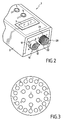
- Figure 2 shows the part of the reading device that receives the the identification connectors to be tested.
- the housing 2 comprises on its front face two connectors 10 and 20 (male or female next the cases) in solidarity with the latter.
- the connector identification 100 is in the form of a male connector which comprises a plurality of pins 101 disposed within a body 105.
- the connector 100 can also be a connector female.
- the body 105 of the connector encloses the electrical circuit of data coding that is connected to the non-visible ends of the pins 101.
- the part of the body 105 that surrounds the pins 101 is formed of a ring 103 which is free in rotation.
- the ring 103 has bayonets 104 intended to cooperate with grooves 11 of the connector 10 corresponding.
- the means fasteners can be of various shapes, for example a thread.
- the connector 20 of the device shown in Figure 2 the connector will include a thread 21 corresponding to screw the identification connector.
- the connectors 10 and 20 each respectively comprise a plurality of cavities of contact 12 and 22 for receiving the pins of the connector and to establish thus an electrical connection between the reading device 1 and the circuit of coding of the identification connector.
- the connectors 10 and 20 are respectively provided with protective connectors 30 and 40 as shown in FIG. 4.
- Each protective connector 30, respectively 40 is permanently attached to the housing 2 by a fastening system 31, respectively 41, such as a cable or the like.
- connectors 30 and 40 enclose a decoding circuit which contains information enabling to perform a self-test of the reading device as explained later in detail.
- the decoding circuit may for example consist of a blank circuit where all the discrete elements are at 1. This feature of the protection connectors allows the operator to check the correct operation of the reading device before read operation of identification connectors to check.
- FIG. 5 shows the main components that are put in in the electronic circuit of the reading apparatus of the present invention.
- the circuit 15 comprises a microcontroller 8 which implements programs stored in an associated memory unit 9.
- the memory unit 9 contains mainly a program (TEST MODE) for connectors equipped with a self test circuit and three playback programs (MODE V.1, V.2 and V.3) identification connectors each corresponding to a model of specific connector.
- the apparatus according to the invention may advantageously comprise connecting means (not shown), such as an RS232 serial port, connected to the microcontroller to update the programs in the device.
- connecting means such as an RS232 serial port
- the microcontroller 8 reads the data contained in the identification connectors via a bus 13 and an input / output interface 7 which may be formed of a matrix to diode for example. More precisely, with each pressure of an operator on one of the keys 4 or 5 the microcontroller 8 will read and decode the bit data of the identification connector corresponding to the information requested by the program. Once the data decoded, the microcontroller visualizes on the display 3 the information corresponding.
- control organs can be software means allowing the information to be displayed one after the other or all together on a display device of suitable size.
- the display of information is successively after each press of an operator on one of the buttons 4 or 5.
- the operator uses only the 4.
- the program detects if the connector in place is a protection connector with a self-test circuit as for the connectors 30 and 40 presented in Figure 4. If this is the case, the result of the self-test is displayed on the display 3 in a step ST2. The operation The self-test of the device will be described in detail later.
- the device raises the binary values on the contacts of connectors 10 and 20. If all values are at 0 so there is no connector plugged in.
- step ST3 which consists of detecting the model of the identification connector present in order to run the program of appropriate reading of information.
- the information relating to the version of the connector is obtained by querying one or more discrete elements of the circuit connected to the pins of the connector which form a code that will interpreted by the program to decode and visualize the version of concerned motor. More precisely, each pin of the connector is identified under a unique reference (eg a letter). So, by addressing one or more pins, the microcontroller will be able to obtain the binary data that it must interpret to obtain the information.
- FIG. 3 shows an example of a connector identification for motors with 26 pins each referenced by letter from A to Z.
- the model (V.1, V.2 or V.3) of the identification connector is recognized by the microcontroller which will then load, from the memory unit 9, the reading software corresponding information (step ST4).
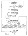
- the software first initiates a parity check step ST5 which consists in adding all or some binary values contained in the connector. If a problem of parity is detected, the microcontroller will then display a message "PARITE?" (Step ST6) on the display 3 to inform the operator. The operation of reading and checking the information contained in the identification connector by the operator can then begin in a step ST7 where the number of increments made by the operator on the button "USE" 4 is stored. Indeed, each time the "USE" button is pressed, the operator will successively display all the information contained in the connector in an order defined by the software. In the example of FIG. 6, the software loaded in the microcontroller will successively display the information as a function of the value n of increments of the button.
- step ST8 if the duration between two button presses is greater than a specified duration, the latter returns to the initial step ST0 which corresponds to the standby state of the device.
- the microcontroller 8 also contains in its unit of memory 9 a program that, in combination with connectors from protection equipped with a self-test circuit (eg blank circuit with discrete elements to 1), allows to perform a self-test of the device of 1.
- a self-test circuit eg blank circuit with discrete elements to 1
- This self-test operation of the device is useful in all where there may be doubt about its operation (eg problem of systematic parity).
- Self test is also useful for controlling the device after a modification (eg microcontroller replacement or Battery).
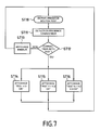
- Figure 7 illustrates the steps of the self-test operation of the apparatus. After pressing the 5 "TEST” button on the playback device the program "TEST MODE” is executed from the memory unit 9 in the microcontroller (step ST10). This self test program is also run in the microcontroller when a connector from protection with a self-test circuit is detected in step ST1 of the figure 5.
- a step ST11 the program detects the location of the connector on the device.
- the connector 20 of FIG. 2 is able to receive the version identification connectors V.1 and V.2 while the connector 10 only receives connectors identification version V.3.
- a step ST12 verification of the presence of a self-test connector is initiated. If the present connector is not detected as a connector of test (i.e. if all or some discrete elements are not at 1), a error message is displayed on the apparatus (step ST13). If the connector in place on the device is well detected as a self test connector (i.e. all discrete elements to be considered are at 1), a message of test result is displayed.
- the device will display the corresponding message.
- the message "TEST V.3 OK” will be displayed (step ST4).
- the message "TEST V.1 V.2 OK” will be displayed (step ST5).
- the message "TEST V.1 V.2 V.3” will be displayed (step ST6).
- the reading apparatus constitutes a tool more reliable and convenient than manual control methods which allows to read in all places and at all times the information contained in an identification connector to ensure their compatibility with the characteristics of the motor on which the connector is or must be installed.
- the information (name of the parameter and its attribute) are directly displayed in clear, making it easier to check for the operator.
Landscapes
- Physics & Mathematics (AREA)
- General Physics & Mathematics (AREA)
- Engineering & Computer Science (AREA)
- Automation & Control Theory (AREA)
- Details Of Connecting Devices For Male And Female Coupling (AREA)
- Coupling Device And Connection With Printed Circuit (AREA)
- Mechanical Coupling Of Light Guides (AREA)
- Manufacturing Of Electrical Connectors (AREA)
- Arrangements For Transmission Of Measured Signals (AREA)
- Test And Diagnosis Of Digital Computers (AREA)
Abstract
Description
La présente invention se rapporte au domaine des connecteurs d'identification utilisés notamment dans les moteurs d'avions dans le paramétrage du calculateur moteur. L'invention concerne plus particulièrement un appareil pour lire le contenu de tels connecteurs avant l'assemblage du moteur à l'avion. L'invention peut être utilisée pour vérifier la programmation des champs modifiables par un opérateur.The present invention relates to the field of connectors identification used in particular in aircraft engines in the parameterization of the engine ECU. The invention relates more especially a device for reading the contents of such connectors before the assembly of the engine to the airplane. The invention can be used to check the programming of the fields modifiable by an operator.
Aujourd'hui, dans l'industrie aéronautique, afin de mieux maítriser les coûts de développement et de fabrication des moteurs, on conçoit un moteur dit "de base" à partir duquel des familles et versions de moteurs spécifiques sont déclinées. De la même façon, les fabricants de calculateurs ont défini un seul type de calculateur par moteur de base qui est capable de fonctionner avec les familles et versions de moteurs dérivées.Today, in the aerospace industry, to better control the costs of developing and manufacturing engines, we conceive a so-called "basic" engine from which families and engine versions specific are declined. Similarly, the manufacturers of calculators have defined a single type of basic engine calculator that is able to work with families and engine versions Derived.
Aussi, le calculateur doit être paramétré en fonction de la famille et de la version du moteur considéré. A cet effet, on utilise un connecteur d'identification qui est solidaire du moteur et qui est connecté au calculateur. Ce connecteur d'identification contient les informations (sous forme codée binaire) relatives aux caractéristiques du moteur qui vont être utilisées par le calculateur.Also, the calculator must be parameterized according to the family and of the engine version considered. For this purpose, a connector is used identification that is integral with the engine and is connected to the computer. This identification connector contains the information (under binary coded form) relating to the characteristics of the engine that are going to be used by the calculator.
La figure 8 illustre un exemple d'un connecteur d'identification
considéré dans la présente invention. Le connecteur d'identification 100
comprend une pluralité de broches 101 qui sont reliées entre elles à
l'intérieur du connecteur par un circuit électrique (non représenté)
reprogrammable ou non.Figure 8 illustrates an example of an identification connector
considered in the present invention. The
Dans le cas d'un circuit électrique non reprogrammable, celui-ci est formé de composants discrets, tels que des pistes à fusibles, qui relient les broches du connecteur. De façon connue, la codification des informations dans le connecteur s'effectue en faisant fondre certaines pistes à fusibles. Ainsi, à chaque broche du connecteur correspond une donnée binaire (0 ou 1). Une fois le connecteur installé sur le moteur (i.e. connecté au calculateur), le calculateur interprète, en binaire, le schéma électrique défini dans le connecteur afin d'acquérir les caractéristiques du moteur.In the case of a non-reprogrammable electrical circuit, this one is formed of discrete components, such as fuse tracks, which connect the connector pins. In known manner, the codification of information in the connector is done by melting some fuse tracks. Thus, at each pin of the connector corresponds a binary data (0 or 1). Once the connector is installed on the motor (i.e. connected to the calculator), the calculator interprets, in binary, the electrical diagram defined in the connector in order to acquire the characteristics of the motor.
Dans le cas d'un circuit électrique reprogrammable, la donnée binaire peut être déterminée par un commutateur par exemple.In the case of a reprogrammable electrical circuit, the data binary can be determined by a switch for example.
La fiabilité des informations contenues dans le connecteur d'identification est d'une importance capitale d'autant plus que les connecteurs ont des clés de détrompage identiques pour pouvoir être installés sur tous les calculateurs. En effet, c'est le connecteur d'identification qui va autoriser ou interdire certaines caractéristiques de fonctionnement propres à chaque famille et version de moteurs. Par exemple, une version ou famille de moteur définie pour une poussée maximale de 20 000 livres peut-être équipée d'un connecteur autorisant une poussée jusqu'à 22 000 livres ou limitant la poussée à 18000 livres. Sachant que certains éléments du moteur ne sont pas adaptés pour une poussée au-delà de 20 000 livres, ou qu'avec une poussée de 18000 livres on peut empêcher le décollage, une telle erreur peut avoir de graves conséquences.The reliability of the information contained in the connector identification is of paramount importance, especially as connectors have identical keying keys to be able to be installed on all calculators. Indeed, it is the connector identification that will allow or prohibit certain characteristics of operation specific to each family and engine version. By example, a version or engine family defined for a thrust maximum of 20,000 pounds may be equipped with a connector allowing a push up to 22,000 pounds or limiting thrust to 18,000 pounds. Knowing that some engine components are not suitable for a pushing beyond 20,000 pounds, or with a push of 18,000 pounds you can prevent the takeoff, such an error can have serious consequences.
L'opération de lecture du connecteur d'identification permet de s'assurer, avant le montage du moteur sous l'aile de l'avion, des caractéristiques du moteur. Ainsi, il est possible d'effectuer un contrôle des choix réalisés à partir des livrets moteur et d'éviter des montages intempestifs inadmissibles vis-à-vis des temps d'immobilisation et des coûts engendrés.The read operation of the identification connector makes it possible to ensure, before mounting the engine under the wing of the aircraft, engine characteristics. Thus, it is possible to carry out a control choices made from the engine booklets and avoid editing inadvertent interference with downtime and costs incurred.
Il existe à l'heure actuelle deux possibilités pour lire les informations contenues dans un connecteur d'identification. La première possibilité consiste à lire manuellement les données brutes (i.e. binaires) présentes dans le connecteur. Cette opération est effectuée par un opérateur qui relève à l'aide d'un ohmmètre la valeur mesurée sur chaque contact du connecteur. Une fois toutes les données relevées, l'opérateur décode ces informations au moyen des documents constructeurs pour vérifier la concordance entre les informations codées dans le connecteur d'identification et les caractéristiques du moteur auquel il doit être associé. Cette première solution constitue une opération manuelle fastidieuse qui implique des risques d'erreur et de détérioration lors des mesures par l'opérateur notamment du fait de la proximité des contacts dans le connecteur.There are currently two possibilities for reading information contained in an identification connector. The first possibility consists of manually reading the raw data (i.e. binary) present in the connector. This operation is performed by an operator who reads with an ohmmeter the value measured on each contact of the connector. Once all the data has been collected, the operator decodes these information through the constructor documents to check the concordance between the information coded in the connector identification and the characteristics of the engine to which it must be associated. This first solution is a tedious manual operation that entails risks of error and deterioration when measuring particularly because of the proximity of the contacts in the connector.
La seconde possibilité actuellement connue pour valider les données contenues dans un connecteur d'identification consiste à monter le moteur, avec le calculateur équipé du connecteur d'identification, sous l'aile de l'avion afin de lire les informations codées dans le connecteur par l'intermédiaire de l'ordinateur de bord. Cette solution est encore plus fastidieuse que la première décrite ci-dessus. Le montage et le démontage du moteur sur l'avion entraínent des coûts en terme de temps et de main d'oeuvre qui ne sont pas admissibles dans ce type d'industrie.The second possibility currently known to validate the data contained in an identification connector is to mount the engine, with the computer equipped with the identification connector, under the wing of the aircraft to read the information coded in the connector by via the on-board computer. This solution is even more tedious than the first described above. Assembly and disassembly of the engine on the plane entail costs in terms of time and hand that are not eligible in this type of industry.
La présente invention vise à remédier aux inconvénients précités et à réaliser un dispositif qui permet de lire de façon plus fiable, plus rapide et sans risque de dégradation les informations contenues dans un connecteur d'identification et ceci sans démonter d'autres pièces du moteur.The present invention aims to remedy the aforementioned drawbacks and to make a device that allows you to read more reliably, faster and without risk of degradation the information contained in a identification connector and this without disassembling other parts of the engine.
Ces buts sont atteints grâce à un appareil de lecture de connecteurs d'identification pour moteur comprenant une pluralité de contacts reliés à un circuit de décodage, chaque contact correspondant à une donnée binaire et une ou plusieurs desdites données binaires correspondant à des informations relatives aux caractéristiques du moteur, caractérisé en ce que l'appareil de lecture comprend des moyens de branchement aptes à recevoir au moins un connecteur d'identification, les moyens de branchement étant reliés à des moyens de traitement réagissant à des organes de commande pour afficher les informations contenues dans le connecteur sur un dispositif d'affichage.These goals are achieved through a connector reading device identification system comprising a plurality of contacts connected to a decoding circuit, each contact corresponding to a datum binary and one or more of said binary data corresponding to information relating to the characteristics of the engine, characterized in that that the reading apparatus comprises connecting means adapted to receive at least one identification connector, the means of connection being connected to processing means responsive to control devices to display the information contained in the connector on a display device.
Ainsi, la présente invention propose un appareil qui permet de lire en clair les informations contenues dans un connecteur d'identification. Un opérateur peut par conséquent vérifier en tous lieux et à tous moments la compatibilité des informations du connecteur se référant aux caractéristiques du moteur sur lequel il doit être branché.Thus, the present invention provides a device that can read in clear the information contained in an identification connector. A operator can therefore check in all places and at all times the compatibility of the connector information referring to characteristics of the engine on which it is to be connected.
Selon une caractéristique de l'invention, les moyens de traitement comprennent des moyens logiciels pour décoder les informations relatives aux caractéristiques du moteur à partir des données binaires lues dans le connecteur d'identification.According to one characteristic of the invention, the treatment means include software means for decoding information relating to to the engine characteristics from the binary data read in the identification connector.
Selon un aspect particulier de l'invention, les organes de commande comprennent un ou plusieurs boutons pour commander l'affichage des informations codées dans le connecteur d'identification branché sur l'appareil de lecture, chaque information étant successivement affichée en réponse à une pression sur le bouton. Alternativement, dans une version automatisé de l'appareil de lecture, les organes de commande peuvent être des moyens logiciels permettant l'affichage des informations les unes après les autres, ou bien toutes ensembles sur un dispositif d'affichage adapté. According to a particular aspect of the invention, the control members include one or more buttons to control the display of coded information in the identification connector connected to the reading apparatus, each piece of information being successively displayed in response to a press on the button. Alternatively, in one version automated reading device, the control devices can be software means allowing the display of information one after the others, or all together on a display device adapted.
Le connecteur d'identification peut être un connecteur multibroche. Dans ce cas, les moyens de branchement de l'appareil de lecture comprennent au moins un connecteur multibroche apte à recevoir le connecteur d'identification.The identification connector may be a multi-pin connector. In this case, the connection means of the reading device comprise at least one multi-pin connector capable of receiving the identification connector.
Selon un mode de réalisation de l'invention, les moyens de branchement comprennent au moins un connecteur pour recevoir chacun au moins un modèle de connecteur d'identification spécifique.According to one embodiment of the invention, the means of connection include at least one connector to receive each at least one specific identification connector model.
Les moyens de traitements comprennent des moyens logiciels pour détecter le modèle du connecteur d'identification branché sur l'appareil.The processing means comprise software means for detect the model of the identification connector connected to the device.
Les moyens de traitements peuvent comprendre également des moyens logiciels pour effectuer un test de parité du circuit de codage du connecteur d'identification.The means of treatment may also include software means for performing a parity test of the coding circuit of the identification connector.
Selon une caractéristique de l'invention, l'appareil de lecture comprend au moins un connecteur de protection comprenant un circuit d'autotest. A cet effet, les moyens de traitement comprennent des moyens logiciels pour effectuer un test de l'appareil de lecture à partir du circuit d'autotest du connecteur de protection. Les organes de commande peuvent comprendre au moins un bouton pour commander l'affichage du résultat du test de l'appareil de lecture ou des moyens logiciels d'affichage automatique du résultat comme décrits plus haut.According to a characteristic of the invention, the reading apparatus comprises at least one protective connector comprising a circuit self-test. For this purpose, the processing means comprise means software for performing a test of the reading apparatus from the circuit self-test protection connector. Control elements may include at least one button to control the display of the test result of the reading device or display software means automatic result as described above.
Selon une caractéristique de l'invention, l'appareil de lecture peut être équipé de moyen de liaison pour mettre à jour les logiciels décrits ci-dessus.According to a characteristic of the invention, the reading apparatus can be equipped with means of connection to update the software described above.
D'autres caractéristiques et avantages de l'invention ressortiront de la description suivante de modes particuliers de réalisation de l'invention, donnés à titre d'exemples non limitatifs, en référence aux dessins annexés, sur lesquels:
- la figure 1 est une vue en perspective de l'appareil de lecture de connecteurs d'identification conformément à un mode de réalisation de l'invention,
- la figure 2 est une vue en perspective d'une partie de l'appareil de lecture conformément à un mode de réalisation de l'invention,
- la figure 3 est une vue schématique de face d'un connecteur d'identification montrant un exemple de disposition des broches de contact,
- la figure 4 est une vue en perspective d'une partie de l'appareil de lecture munie de connecteurs d'autotest conformément à un mode de réalisation de l'invention,
- la figure 5 est une vue schématique du circuit de contrôle de l'appareil de lecture selon un mode de réalisation de l'invention,
- la figure 6 est un organigramme montrant les étapes de lecture et de vérification des connecteurs d'identification conformément à un mode de réalisation de l'invention,
- la figure 7 est un organigramme montrant les étapes d'une procédure de test de l'appareil de lecture conformément à un mode de réalisation de l'invention,
- la figure 8 est une perspective en vue partielle d'un exemple de connecteur d'identification pour moteur d'avion.
- FIG. 1 is a perspective view of the identification connector reading apparatus according to one embodiment of the invention;
- FIG. 2 is a perspective view of a part of the reading apparatus according to an embodiment of the invention,
- FIG. 3 is a diagrammatic front view of an identification connector showing an example of arrangement of the contact pins,
- FIG. 4 is a perspective view of a portion of the reading apparatus provided with self-test connectors according to one embodiment of the invention,
- FIG. 5 is a schematic view of the control circuit of the reading apparatus according to one embodiment of the invention,
- FIG. 6 is a flowchart showing the steps of reading and checking the identification connectors in accordance with one embodiment of the invention,
- Fig. 7 is a flowchart showing the steps of a test procedure of the reading apparatus according to an embodiment of the invention,
- Figure 8 is a partial view of an example of an aircraft engine identification connector.
La figure 1 représente un appareil de lecture 1 de connecteurs
d'identification selon l'invention présenté du côté de sa face supérieure.
L'appareil de lecture 1 est formé d'un boítier 2 qui comprend deux boutons
4 et 5 ainsi qu'un afficheur 3 tel qu'un écran LCD par exemple. Les
boutons 4 et 5 servent de moyens de commande à l'opérateur pour
visualiser des informations sur l'afficheur 3. Le boítier 2 comprend
également deux connecteurs 10 et 20 destinés à recevoir et à s'adapter
avec des connecteurs d'identification 100. L'appareil de lecture selon
l'invention étant portatif, le boítier 2 comprend en outre des moyens
d'alimentation autonome, comme par exemple quatre piles de 1,5 volts,
qui sont logées dans un tiroir 6 à l'intérieur du boítier 2. Selon une
variante, le tiroir 6 peut constituer un logement pour une batterie
rechargeable. Dans ce cas, le tiroir 6 peut comprendre des moyens pour
connecter un chargeur à la batterie.Figure 1 shows a
La figure 2 montre la partie de l'appareil de lecture qui reçoit le ou
les connecteurs d'identification à tester. A cet effet, le boítier 2 comprend
sur sa face avant deux connecteurs 10 et 20 (mâles ou femelles suivant
les cas) solidaires de ce dernier. Comme illustré en figure 8, le connecteur
d'identification 100 se présente sous la forme d'un connecteur mâle qui
comprend une pluralité de broches 101 disposées à l'intérieur d'un corps
105. Suivant les cas, le connecteur 100 peut être aussi un connecteur
femelle. Le corps 105 du connecteur renferme le circuit électrique de
codage des données qui est relié aux extrémités non visibles des broches
101. La partie du corps 105 qui entoure les broches 101 est formée d'une
bague 103 qui est libre en rotation. Dans le mode de réalisation de
connecteur d'identification illustré en figure 8, la bague 103 comporte des
baïonnettes 104 destinées à coopérer avec des gorges 11 du connecteur
10 correspondant. Toutefois, suivant le modèle du connecteur, les moyens
de fixation peuvent être de formes variées comme par exemple un
filetage. Dans ce cas, comme illustré pour le connecteur 20 de l'appareil
représenté en figure 2, le connecteur comportera un filetage 21
correspondant pour visser le connecteur d'identification. Les connecteurs
10 et 20 comprennent chacun respectivement une pluralité de cavités de
contact 12 et 22 destinées à recevoir les broches du connecteur et établir
ainsi une connexion électrique entre l'appareil de lecture 1 et le circuit de
codage du connecteur d'identification. Figure 2 shows the part of the reading device that receives the
the identification connectors to be tested. For this purpose, the
Lorsque l'appareil de lecture 1 n'est pas utilisé, les connecteurs 10
et 20 sont munis respectivement de connecteurs de protection 30 et 40
tels que représentés en figure 4. Chaque connecteur de protection 30,
respectivement 40, est attaché de façon permanente au boítier 2 par un
système d'attache 31, respectivement 41, tel qu'un câble ou similaire. En
outre de leur fonction de protection, les connecteurs 30 et 40 renferment
un circuit de décodage qui contient des informations permettant
d'effectuer un autotest de l'appareil de lecture comme expliqué plus loin
en détail. A cet effet, le circuit de décodage peut consister par exemple en
un circuit vierge où tous les éléments discrets sont à 1. Cette
fonctionnalité des connecteurs de protection permet à l'opérateur de
contrôler le bon fonctionnement de l'appareil de lecture avant une
opération de lecture de connecteurs d'identification à vérifier.When the
La figure 5 montre les principaux composants qui sont mis en
oeuvre dans le circuit électronique de l'appareil de lecture de la présente
invention. Le circuit 15 comprend un microcontrôleur 8 qui implémente
des programmes stockés dans une unité de mémoire 9 associée. Dans
l'exemple illustré, l'unité de mémoire 9 contient principalement un
programme de lecture (MODE TEST) pour des connecteurs équipés d'un
circuit d'autotest et trois programmes de lecture (MODE V.1, V.2 et V.3)
de connecteurs d'identification correspondant chacun à un modèle de
connecteur spécifique.Figure 5 shows the main components that are put in
in the electronic circuit of the reading apparatus of the present
invention. The
L'appareil selon l'invention peut comprendre avantageusement des moyens de liaison (non représentés), telle q'un port série RS232, reliés au microcontrôleur pour mettre à jour les programmes dans l'appareil.The apparatus according to the invention may advantageously comprise connecting means (not shown), such as an RS232 serial port, connected to the microcontroller to update the programs in the device.
Le microcontrôleur 8 effectue la lecture des données contenues
dans les connecteurs d'identification par l'intermédiaire d'un bus 13 et
d'une interface d'entrée/sortie 7 qui peut être formée d'une matrice à
diode par exemple. Plus précisément, à chaque pression d'un opérateur
sur une des touches 4 ou 5 le microcontrôleur 8 va lire et décoder les
données binaires du connecteur d'identification correspondant à
l'information demandée par le programme. Une fois les données
décodées, le microcontrôleur visualise sur l'afficheur 3 l'information
correspondante.The
Alternativement, dans une version automatisé de l'appareil de lecture, les organes de commande peuvent être des moyens logiciels permettant l'affichage des informations les unes après les autres ou bien toutes ensembles sur un dispositif d'affichage de taille adaptée.Alternatively, in an automated version of the device reading, the control organs can be software means allowing the information to be displayed one after the other or all together on a display device of suitable size.
Le procédé de lecture des informations contenues dans un connecteur d'identification mis en oeuvre dans l'appareil selon l'invention va être décrit en relation avec la figure 6.The process of reading the information contained in a identification connector used in the apparatus according to the invention will be described in connection with Figure 6.
Comme décrit ci-dessus, l'affichage des informations s'effectue
successivement après chaque pression d'un opérateur sur un des boutons
4 ou 5. Pour l'opération de lecture des informations contenues dans un
connecteur d'identification à vérifier, l'opérateur utilise uniquement la
touche "USE" 4. Ainsi, après avoir placé un connecteur d'identification sur
un des connecteurs femelles de l'appareil, l'opérateur appuie une première
fois sur la touche "USE" 4 dans une étape initiale ST0 qui va lancer le
déroulement du programme principal dans le microcontrôleur. Dans une
étape ST1, le programme détecte si le connecteur en place est un
connecteur de protection avec un circuit d'autotest comme pour les
connecteurs 30 et 40 présentés en figure 4. Si tel est le cas, le résultat de
l'autotest est visualisé sur l'afficheur 3 dans une étape ST2. L'opération
d'autotest de l'appareil sera décrit en détail plus loin.As described above, the display of information is
successively after each press of an operator on one of the
Pour détecter la présence de connecteurs, l'appareil relève les
valeurs binaires sur les contacts des connecteurs 10 et 20. Si toutes les
valeurs sont à 0 alors il n'y a aucun connecteur branché.To detect the presence of connectors, the device raises the
binary values on the contacts of
Si le circuit du connecteur détecté n'est pas reconnu comme un circuit d'autotest, on passe à l'étape ST3 qui consiste à détecter le modèle du connecteur d'identification présent afin d'exécuter le programme de lecture d'informations approprié. Comme pour toutes les informations contenues dans le connecteur, l'information relative à la version du connecteur s'obtient par interrogation d'un ou plusieurs éléments discrets du circuit reliés aux broches du connecteur qui forment un code qui sera interprété par le programme pour décoder et visualiser la version du moteur concerné. Plus précisément, chaque broche du connecteur est identifiée sous une référence unique (ex. une lettre). Ainsi, en adressant une ou plusieurs broches, le microcontrôleur pourra obtenir la ou les données binaires qu'il doit interpréter pour obtenir l'information.If the detected connector circuit is not recognized as a self-test circuit, we go to step ST3 which consists of detecting the model of the identification connector present in order to run the program of appropriate reading of information. As for all information contained in the connector, the information relating to the version of the connector is obtained by querying one or more discrete elements of the circuit connected to the pins of the connector which form a code that will interpreted by the program to decode and visualize the version of concerned motor. More precisely, each pin of the connector is identified under a unique reference (eg a letter). So, by addressing one or more pins, the microcontroller will be able to obtain the binary data that it must interpret to obtain the information.
A titre d'exemple, dans une même gamme de moteurs, on trouve
plusieurs modèles de moteurs à chacun desquels correspond un
connecteur d'identification spécifique. Chacun des connecteurs contient un
circuit de décodage qui définit des caractéristiques propres au modèle du
moteur telles que le régime de surpuissance autorisé, les options de
régulation, la vitesse de rotation de l'arbre moteur.... Toutes ces
caractéristiques sont codées en binaires dans les éléments discrets du
connecteur d'identification. La figure 3 montre un exemple de connecteur
d'identification pour moteurs comprenant 26 broches chacune référencée
par une lettre allant de A à Z. Dans cet exemple, on considère que le
connecteur 20 de la figure 2 est apte à recevoir les connecteurs
d'identification pour deux modèles de moteurs différents alors que le
connecteur 10 ne reçoit que des connecteurs d'identification pour un
même modèle de moteur. Ainsi, par exemple, sur le connecteur 10, la
valeur de l'élément discret relié à la broche W déterminera le modèle du
moteur qui correspond au connecteur en place. En d'autres termes, si
W=0 alors le connecteur est un modèle V.1 et si W=1 le connecteur
correspond au modèle V.2 par exemple.For example, in the same range of engines, we find
several models of engines to each of which corresponds a
specific identification connector. Each of the connectors contains a
decoding circuit which defines characteristics specific to the model of the
such as the authorized overpower scheme,
regulation, the speed of rotation of the motor shaft .... All these
characteristics are coded in binary in the discrete elements of the
identification connector. Figure 3 shows an example of a connector
identification for motors with 26 pins each referenced
by letter from A to Z. In this example, we consider that the
De par le connecteur 10 ou 20 occupé et, le cas échéant, selon des
données mesurées sur le connecteur d'identification, le modèle (V.1, V.2
ou V.3) du connecteur d'identification est reconnu par le microcontrôleur
qui va alors charger, à partir de l'unité de mémoire 9, le logiciel de lecture
des informations correspondant (étape ST4).Through
Le logiciel initie tout d'abord une étape ST5 de vérification de parité
qui consiste à additionner toutes ou certaines valeurs binaires contenues
dans le connecteur. Si un problème de parité est détecté, le
microcontrôleur affichera alors un message "PARITE ?" (étape ST6) sur
l'afficheur 3 afin d'en informer l'opérateur. L'opération de lecture et de
vérification des informations contenues dans le connecteur d'identification
par l'opérateur peut alors débuter dans une étape ST7 où le nombre
d'incrémentations effectuées par l'opérateur sur le bouton "USE" 4 est
mémorisée. En effet, à chaque pression sur le bouton "USE", l'opérateur
affichera successivement toutes les informations contenues dans le
connecteur selon un ordre défini par le logiciel. Sur l'exemple de la figure
6, le logiciel chargé dans le microcontrôleur affichera successivement les
informations en fonction de la valeur n d'incrémentations du bouton. Dans
cet exemple six messages d'information sont affichés dans des étapes
ST71 à ST76. Ils correspondent respectivement à la famille du moteur
(n=1), au numéro de série de celui-ci (n=2), à son modèle (n=3), au
régime de surpuissance qu'il autorise (n=4), au type de liaison de son
régulateur (n=5) et au régime de rotation de l'arbre haute pression (n=6).
Plus précisément, à chaque pression sur le bouton, l'afficheur 3 indique le
nom du paramètre suivi de sa valeur ou de sa caractéristique. Si une des
informations ne peut être lue (codage non reconnu), un message d'erreur
sera affiché à la place de l'information correspondante indiquant ainsi à
l'opérateur que le connecteur n'est pas valide.The software first initiates a parity check step ST5 which consists in adding all or some binary values contained in the connector. If a problem of parity is detected, the microcontroller will then display a message "PARITE?" (Step ST6) on the
Lorsqu'un problème de parité a été détecté, le message "PARITE ?" continuera de s'afficher alternativement avec les informations lues dans le connecteur. D'autre part, dans une étape ST8, si la durée entre deux pressions sur le bouton est supérieure à une durée déterminée, ce dernier revient à la l'étape initiale ST0 qui correspond à l'état de veille de l'appareil.When a parity problem has been detected, the message "PARITE?" will continue to appear alternately with the information read in the connector. On the other hand, in a step ST8, if the duration between two button presses is greater than a specified duration, the latter returns to the initial step ST0 which corresponds to the standby state of the device.
Le microcontrôleur 8 contient également dans son unité de
mémoire 9 un programme qui, en association avec des connecteurs de
protection équipés d'un circuit d'autotest (ex. circuit vierge avec les
éléments discrets à 1), permet de réaliser un autotest de l'appareil de
lecture 1. Cette opération d'autotest de l'appareil est utile dans tous les
cas où il peut y avoir un doute sur son fonctionnement (ex. problème de
parité systématique). L'autotest est également utile pour contrôler
l'appareil après une modification (ex. remplacement de microcontrôleur ou
piles).The
La figure 7 illustre les étapes de l'opération d'autotest de l'appareil. Après avoir pressé sur le bouton 5 "TEST" de l'appareil de lecture le programme "MODE TEST" est exécuté à partir de l'unité de mémoire 9 dans le microcontrôleur (étape ST10). Ce programme d'autotest est également exécuté dans le microcontrôleur lorsque qu'un connecteur de protection avec un circuit d'autotest est détecté dans l'étape ST1 de la figure 5.Figure 7 illustrates the steps of the self-test operation of the apparatus. After pressing the 5 "TEST" button on the playback device the program "TEST MODE" is executed from the memory unit 9 in the microcontroller (step ST10). This self test program is also run in the microcontroller when a connector from protection with a self-test circuit is detected in step ST1 of the figure 5.
Dans une étape ST11, le programme détecte l'emplacement du
connecteur sur l'appareil. Comme pour l'exemple décrit précédemment à
la figure 5 en relation avec l'appareil illustré à la figure 2, le connecteur 20
de la figure 2 est apte à recevoir les connecteurs d'identification versions
V.1 et V.2 alors que le connecteur 10 ne reçoit que des connecteurs
d'identification version V.3. Une fois un connecteur détecté, une étape
ST12 de vérification de la présence d'un connecteur d'autotest est initiée.
Si le connecteur présent n'est pas détecté comme étant un connecteur de
test (i.e. si tous ou certains éléments discrets ne sont pas à 1), un
message d'erreur est affiché sur l'appareil (étape ST13). Si le connecteur
en place sur l'appareil est bien détecté comme un connecteur d'autotest
(i.e. tous les éléments discrets à considérés sont à 1), un message de
résultat de test est affiché. Selon la présence d'un ou deux connecteurs
sur l'appareil, ce dernier affichera le message correspondant. Dans
l'exemple considéré, si un seul connecteur est branché sur le connecteur
10, qui ne reçoit que des connecteurs d'identification type V.3, le message
"TEST V.3 OK" sera affiché (étape ST4). Si un seul connecteur est branché
sur le connecteur 20, qui ne reçoit que des connecteurs d'identification
type V.1 ou V.2, le message "TEST V.1 V.2 OK" sera affiché (étape ST5).
Enfin, Si deux connecteurs d'autotest sont branchés sur les deux prises 10
et 20 de l'appareil, le message "TEST V.1 V.2 V.3" sera affiché (étape
ST6).In a step ST11, the program detects the location of the
connector on the device. As for the example described previously in
FIG. 5 in connection with the apparatus illustrated in FIG. 2, the
Ainsi, l'appareil de lecture selon la présente invention constitue un outil plus fiable et plus pratique que les méthodes de contrôle manuelles qui permet de lire en tous lieux et à tous moments les informations contenues dans un connecteur d'identification afin de s'assurer de leur compatibilité avec les caractéristiques du moteur sur lequel le connecteur est ou doit être installé. Les informations (nom du paramètre et son attribut) sont directement affichées en clair, ce qui facilite la tâche de vérification pour l'opérateur.Thus, the reading apparatus according to the present invention constitutes a tool more reliable and convenient than manual control methods which allows to read in all places and at all times the information contained in an identification connector to ensure their compatibility with the characteristics of the motor on which the connector is or must be installed. The information (name of the parameter and its attribute) are directly displayed in clear, making it easier to check for the operator.
Claims (14)
caractérisé en ce que l'appareil de lecture (1) comprend des moyens de branchement (10, 20) aptes à recevoir au moins un connecteur d'identification, lesdits moyens de branchement étant reliés à des moyens de traitement (8) réagissant à des organes de commande pour afficher les informations contenues dans le connecteur sur un dispositif d'affichage (3).Apparatus for reading (1) identification connectors (100) for an aircraft engine, said connector comprising a plurality of contacts (101) connected to a decoding circuit, each contact corresponding to a binary data, one or more of said data bits corresponding to information relating to the characteristics of the engine,
characterized in that the reading apparatus (1) comprises connecting means (10, 20) adapted to receive at least one identification connector, said connecting means being connected to processing means (8) responsive to actuators for displaying the information contained in the connector on a display device (3).
Applications Claiming Priority (2)
| Application Number | Priority Date | Filing Date | Title |
|---|---|---|---|
| FR0213094 | 2002-10-21 | ||
| FR0213094A FR2846110B1 (en) | 2002-10-21 | 2002-10-21 | APPARATUS FOR READING IDENTIFICATION CONNECTORS |
Publications (2)
| Publication Number | Publication Date |
|---|---|
| EP1418478A1 true EP1418478A1 (en) | 2004-05-12 |
| EP1418478B1 EP1418478B1 (en) | 2007-04-11 |
Family
ID=32050590
Family Applications (1)
| Application Number | Title | Priority Date | Filing Date |
|---|---|---|---|
| EP03292576A Expired - Lifetime EP1418478B1 (en) | 2002-10-21 | 2003-10-16 | Apparatus for reading identification connectors |
Country Status (9)
| Country | Link |
|---|---|
| US (1) | US7078886B2 (en) |
| EP (1) | EP1418478B1 (en) |
| JP (1) | JP4074576B2 (en) |
| AT (1) | ATE359543T1 (en) |
| CA (1) | CA2444984C (en) |
| DE (1) | DE60313104T2 (en) |
| ES (1) | ES2285063T3 (en) |
| FR (1) | FR2846110B1 (en) |
| PT (1) | PT1418478E (en) |
Families Citing this family (4)
| Publication number | Priority date | Publication date | Assignee | Title |
|---|---|---|---|---|
| DE102005048248B4 (en) * | 2005-10-07 | 2015-12-03 | Amphenol-Tuchel Electronics Gmbh | Terminator for antenna systems and plug connection with such a terminator |
| FR2951562B1 (en) * | 2009-10-15 | 2012-06-29 | Airbus Operations Sas | SECURE METHOD FOR ACCESSING AN AIRCRAFT INFORMATION SYSTEM |
| DE102010028263A1 (en) * | 2010-04-27 | 2011-10-27 | Airbus Operations Gmbh | Method and device for identifying an assignment of control loops to at least one control device |
| DE102022129504A1 (en) * | 2022-11-08 | 2024-05-08 | Rolls-Royce Deutschland Ltd & Co Kg | Electric propulsion unit for an aircraft |
Citations (7)
| Publication number | Priority date | Publication date | Assignee | Title |
|---|---|---|---|---|
| US4571488A (en) * | 1985-01-29 | 1986-02-18 | E. I. Du Pont De Nemours And Company | Heat-fusion pipe fitting system |
| US4720253A (en) * | 1985-02-15 | 1988-01-19 | Elastogran Maschinenbau Gmbh | Program-controlled apparatus for the production of moldings from multicomponent plastic, in particular polyurethane |
| EP0366854A2 (en) * | 1988-11-01 | 1990-05-09 | Nova Biomedical Corporation | Controlling machine operation with respect to consumable accessory units |
| US5014794A (en) * | 1988-07-08 | 1991-05-14 | Atlas Copco Ab | Power driven tool and drive system therefor |
| EP1151920A1 (en) * | 2000-05-05 | 2001-11-07 | EDOMAT (Deutschland) Treuhand- und Vermögensverwaltungsgesellschaft mbH | Managing method used during the inspection of aeronautical components |
| US6407554B1 (en) * | 1997-07-21 | 2002-06-18 | Bayerische Motoren Werke Aktiengesellschaft | Diagnostic tester for electronic control devices in a variety of motor vehicle types |
| EP1246345A1 (en) * | 2001-03-23 | 2002-10-02 | Grundfos A/S | Electrical motor with electronic control |
Family Cites Families (6)
| Publication number | Priority date | Publication date | Assignee | Title |
|---|---|---|---|---|
| US4280185A (en) * | 1979-08-06 | 1981-07-21 | United Technologies Corporation | Engine module life tracking system |
| US4787053A (en) * | 1981-12-30 | 1988-11-22 | Semco Instruments, Inc. | Comprehensive engine monitor and recorder |
| DE3229065C2 (en) * | 1982-08-04 | 1984-09-27 | Daimler-Benz Ag, 7000 Stuttgart | Tachometer with economy field |
| US5146172A (en) * | 1990-08-15 | 1992-09-08 | Sundstrand Corp. | Engine identification system |
| US6044700A (en) * | 1997-10-14 | 2000-04-04 | Endevco Corporation | Aircraft equipment configuration identification interface guide |
| US6570385B1 (en) * | 2001-03-19 | 2003-05-27 | Actron Manufacturing Co. | Handheld tester for starting/charging systems |
-
2002
- 2002-10-21 FR FR0213094A patent/FR2846110B1/en not_active Expired - Fee Related
-
2003
- 2003-10-16 PT PT03292576T patent/PT1418478E/en unknown
- 2003-10-16 EP EP03292576A patent/EP1418478B1/en not_active Expired - Lifetime
- 2003-10-16 DE DE60313104T patent/DE60313104T2/en not_active Expired - Lifetime
- 2003-10-16 AT AT03292576T patent/ATE359543T1/en not_active IP Right Cessation
- 2003-10-16 ES ES03292576T patent/ES2285063T3/en not_active Expired - Lifetime
- 2003-10-17 JP JP2003357857A patent/JP4074576B2/en not_active Expired - Lifetime
- 2003-10-20 US US10/687,995 patent/US7078886B2/en not_active Expired - Lifetime
- 2003-10-20 CA CA2444984A patent/CA2444984C/en not_active Expired - Lifetime
Patent Citations (7)
| Publication number | Priority date | Publication date | Assignee | Title |
|---|---|---|---|---|
| US4571488A (en) * | 1985-01-29 | 1986-02-18 | E. I. Du Pont De Nemours And Company | Heat-fusion pipe fitting system |
| US4720253A (en) * | 1985-02-15 | 1988-01-19 | Elastogran Maschinenbau Gmbh | Program-controlled apparatus for the production of moldings from multicomponent plastic, in particular polyurethane |
| US5014794A (en) * | 1988-07-08 | 1991-05-14 | Atlas Copco Ab | Power driven tool and drive system therefor |
| EP0366854A2 (en) * | 1988-11-01 | 1990-05-09 | Nova Biomedical Corporation | Controlling machine operation with respect to consumable accessory units |
| US6407554B1 (en) * | 1997-07-21 | 2002-06-18 | Bayerische Motoren Werke Aktiengesellschaft | Diagnostic tester for electronic control devices in a variety of motor vehicle types |
| EP1151920A1 (en) * | 2000-05-05 | 2001-11-07 | EDOMAT (Deutschland) Treuhand- und Vermögensverwaltungsgesellschaft mbH | Managing method used during the inspection of aeronautical components |
| EP1246345A1 (en) * | 2001-03-23 | 2002-10-02 | Grundfos A/S | Electrical motor with electronic control |
Also Published As
| Publication number | Publication date |
|---|---|
| FR2846110A1 (en) | 2004-04-23 |
| JP4074576B2 (en) | 2008-04-09 |
| CA2444984C (en) | 2012-04-24 |
| EP1418478B1 (en) | 2007-04-11 |
| FR2846110B1 (en) | 2005-01-28 |
| DE60313104D1 (en) | 2007-05-24 |
| DE60313104T2 (en) | 2008-01-03 |
| PT1418478E (en) | 2007-07-18 |
| US7078886B2 (en) | 2006-07-18 |
| JP2004179152A (en) | 2004-06-24 |
| ES2285063T3 (en) | 2007-11-16 |
| US20040133396A1 (en) | 2004-07-08 |
| CA2444984A1 (en) | 2004-04-21 |
| ATE359543T1 (en) | 2007-05-15 |
Similar Documents
| Publication | Publication Date | Title |
|---|---|---|
| FR2785066A1 (en) | Aid for maintenance of complex system such as an aircraft, particularly replacement of helicopter blade attachments | |
| EP1851008A1 (en) | Equipment comprising at least one rotary member and means for measuring vibrational frequencies of said member to determine its wear condition, corresponding control unit and method | |
| FR2800190A1 (en) | METHOD AND SYSTEM FOR THE SELF-DIAGNOSIS OF A CAR | |
| CA2444984C (en) | Reading device for identification connectors | |
| EP3842185A1 (en) | Method for assisting with the maintenance of an industrial tool, corresponding tool and system, and program implementing the method | |
| EP2866106B1 (en) | Apparatus for duplicating usage parameters written in the non-volatile memory of an industrial tool | |
| EP0635789B1 (en) | Microcontroller integrated circuit with read only memory containing test program, test station and corresponding manufacturing process | |
| EP3376388A1 (en) | A communication method for communicating computer data between at least one aircraft and at least one separate piece of electronic equipment | |
| EP4127911A1 (en) | Devices and method for managing electronic control units of a motor vehicle | |
| EP1929379B1 (en) | Device and method for controlling an equipment | |
| FR2641095A1 (en) | ||
| EP1998183A1 (en) | Diagnosis assistance system for an automobile vehicle | |
| EP1105797A1 (en) | Computer-assisted downloading device, in particular for flight management units | |
| EP1605325A2 (en) | Device for transferring data for updating the programmation of a monitoring system of a electric motor | |
| EP1076274B1 (en) | Process for the configuration of a system structured around at least a digital network, and including, at least an either analog or on-off intelligent component | |
| EP2110747A1 (en) | Method for backing up and recovering computer files | |
| EP0297964A1 (en) | Procedure for equipment control through a local network, especially for automation of a workshop | |
| EP1576476A1 (en) | Circuit for monitoring a microprocessor and analysis tool and inputs/outputs thereof | |
| FR2878043A1 (en) | Information e.g. mounts and optical glass size templates catalogue information, loading system for automated machine, has module to store information to be loaded in machine, where module and machine include complementary connection units | |
| FR2986578A1 (en) | Case for controlling water pump, has communication interface that allows machine-to-machine communication, set of electrical contacts that is arranged on printed circuit board, and corresponding hole is arranged in casing | |
| FR2716017A1 (en) | Multi-application electronic structure, and methods for its implementation. | |
| EP1099304A1 (en) | Device for automatically adjusting an electronic card component, in particular a potentiometer | |
| FR3033196A1 (en) | DYNAMIC BEHAVIOR BEHAVIOR ASSEMBLY TEST METHOD AND SYSTEM (STARTER KEY / STARTER SWITCH) OF VEHICLE GMP | |
| FR2861481A1 (en) | Programmable logic array designing environment, has module managing interface permitting user to graphically design functional blocks, and assembling module routing portions of codes associated to blocks and hub so as to obtain file | |
| FR2890199A1 (en) | Digital computer testing method for e.g. weapon aircraft, involves transmitting two lists of calculated variables and parameters to computer, and recording and displaying values of two lists on installation and module, respectively |
Legal Events
| Date | Code | Title | Description |
|---|---|---|---|
| PUAI | Public reference made under article 153(3) epc to a published international application that has entered the european phase |
Free format text: ORIGINAL CODE: 0009012 |
|
| 17P | Request for examination filed |
Effective date: 20031020 |
|
| AK | Designated contracting states |
Kind code of ref document: A1 Designated state(s): AT BE BG CH CY CZ DE DK EE ES FI FR GB GR HU IE IT LI LU MC NL PT RO SE SI SK TR |
|
| AX | Request for extension of the european patent |
Extension state: AL LT LV MK |
|
| AKX | Designation fees paid |
Designated state(s): AT BE BG CH CY CZ DE DK EE ES FI FR GB GR HU IE IT LI LU MC NL PT RO SE SI SK TR |
|
| RAP1 | Party data changed (applicant data changed or rights of an application transferred) |
Owner name: SNECMA SERVICES Owner name: HISPANO SUIZA |
|
| GRAP | Despatch of communication of intention to grant a patent |
Free format text: ORIGINAL CODE: EPIDOSNIGR1 |
|
| GRAS | Grant fee paid |
Free format text: ORIGINAL CODE: EPIDOSNIGR3 |
|
| GRAA | (expected) grant |
Free format text: ORIGINAL CODE: 0009210 |
|
| AK | Designated contracting states |
Kind code of ref document: B1 Designated state(s): AT BE BG CH CY CZ DE DK EE ES FI FR GB GR HU IE IT LI LU MC NL PT RO SE SI SK TR |
|
| PG25 | Lapsed in a contracting state [announced via postgrant information from national office to epo] |
Ref country code: FI Free format text: LAPSE BECAUSE OF FAILURE TO SUBMIT A TRANSLATION OF THE DESCRIPTION OR TO PAY THE FEE WITHIN THE PRESCRIBED TIME-LIMIT Effective date: 20070411 Ref country code: SI Free format text: LAPSE BECAUSE OF FAILURE TO SUBMIT A TRANSLATION OF THE DESCRIPTION OR TO PAY THE FEE WITHIN THE PRESCRIBED TIME-LIMIT Effective date: 20070411 |
|
| REG | Reference to a national code |
Ref country code: GB Ref legal event code: FG4D Free format text: NOT ENGLISH |
|
| REG | Reference to a national code |
Ref country code: CH Ref legal event code: EP |
|
| REG | Reference to a national code |
Ref country code: IE Ref legal event code: FG4D Free format text: LANGUAGE OF EP DOCUMENT: FRENCH |
|
| REF | Corresponds to: |
Ref document number: 60313104 Country of ref document: DE Date of ref document: 20070524 Kind code of ref document: P |
|
| REG | Reference to a national code |
Ref country code: PT Ref legal event code: SC4A Free format text: AVAILABILITY OF NATIONAL TRANSLATION Effective date: 20070706 |
|
| REG | Reference to a national code |
Ref country code: SE Ref legal event code: TRGR |
|
| GBT | Gb: translation of ep patent filed (gb section 77(6)(a)/1977) |
Effective date: 20070718 |
|
| REG | Reference to a national code |
Ref country code: ES Ref legal event code: FG2A Ref document number: 2285063 Country of ref document: ES Kind code of ref document: T3 |
|
| PG25 | Lapsed in a contracting state [announced via postgrant information from national office to epo] |
Ref country code: AT Free format text: LAPSE BECAUSE OF FAILURE TO SUBMIT A TRANSLATION OF THE DESCRIPTION OR TO PAY THE FEE WITHIN THE PRESCRIBED TIME-LIMIT Effective date: 20070411 |
|
| PG25 | Lapsed in a contracting state [announced via postgrant information from national office to epo] |
Ref country code: CZ Free format text: LAPSE BECAUSE OF FAILURE TO SUBMIT A TRANSLATION OF THE DESCRIPTION OR TO PAY THE FEE WITHIN THE PRESCRIBED TIME-LIMIT Effective date: 20070411 Ref country code: BG Free format text: LAPSE BECAUSE OF FAILURE TO SUBMIT A TRANSLATION OF THE DESCRIPTION OR TO PAY THE FEE WITHIN THE PRESCRIBED TIME-LIMIT Effective date: 20070711 Ref country code: DK Free format text: LAPSE BECAUSE OF FAILURE TO SUBMIT A TRANSLATION OF THE DESCRIPTION OR TO PAY THE FEE WITHIN THE PRESCRIBED TIME-LIMIT Effective date: 20070411 |
|
| PLBE | No opposition filed within time limit |
Free format text: ORIGINAL CODE: 0009261 |
|
| STAA | Information on the status of an ep patent application or granted ep patent |
Free format text: STATUS: NO OPPOSITION FILED WITHIN TIME LIMIT |
|
| PG25 | Lapsed in a contracting state [announced via postgrant information from national office to epo] |
Ref country code: SK Free format text: LAPSE BECAUSE OF FAILURE TO SUBMIT A TRANSLATION OF THE DESCRIPTION OR TO PAY THE FEE WITHIN THE PRESCRIBED TIME-LIMIT Effective date: 20070411 |
|
| 26N | No opposition filed |
Effective date: 20080114 |
|
| PG25 | Lapsed in a contracting state [announced via postgrant information from national office to epo] |
Ref country code: IT Free format text: LAPSE BECAUSE OF FAILURE TO SUBMIT A TRANSLATION OF THE DESCRIPTION OR TO PAY THE FEE WITHIN THE PRESCRIBED TIME-LIMIT Effective date: 20070411 Ref country code: GR Free format text: LAPSE BECAUSE OF FAILURE TO SUBMIT A TRANSLATION OF THE DESCRIPTION OR TO PAY THE FEE WITHIN THE PRESCRIBED TIME-LIMIT Effective date: 20070712 |
|
| PG25 | Lapsed in a contracting state [announced via postgrant information from national office to epo] |
Ref country code: MC Free format text: LAPSE BECAUSE OF NON-PAYMENT OF DUE FEES Effective date: 20071031 Ref country code: RO Free format text: LAPSE BECAUSE OF FAILURE TO SUBMIT A TRANSLATION OF THE DESCRIPTION OR TO PAY THE FEE WITHIN THE PRESCRIBED TIME-LIMIT Effective date: 20070411 |
|
| REG | Reference to a national code |
Ref country code: CH Ref legal event code: PL |
|
| PG25 | Lapsed in a contracting state [announced via postgrant information from national office to epo] |
Ref country code: LI Free format text: LAPSE BECAUSE OF NON-PAYMENT OF DUE FEES Effective date: 20071031 Ref country code: CH Free format text: LAPSE BECAUSE OF NON-PAYMENT OF DUE FEES Effective date: 20071031 |
|
| PG25 | Lapsed in a contracting state [announced via postgrant information from national office to epo] |
Ref country code: EE Free format text: LAPSE BECAUSE OF FAILURE TO SUBMIT A TRANSLATION OF THE DESCRIPTION OR TO PAY THE FEE WITHIN THE PRESCRIBED TIME-LIMIT Effective date: 20070411 |
|
| PG25 | Lapsed in a contracting state [announced via postgrant information from national office to epo] |
Ref country code: CY Free format text: LAPSE BECAUSE OF FAILURE TO SUBMIT A TRANSLATION OF THE DESCRIPTION OR TO PAY THE FEE WITHIN THE PRESCRIBED TIME-LIMIT Effective date: 20070411 |
|
| PG25 | Lapsed in a contracting state [announced via postgrant information from national office to epo] |
Ref country code: LU Free format text: LAPSE BECAUSE OF NON-PAYMENT OF DUE FEES Effective date: 20071016 |
|
| PG25 | Lapsed in a contracting state [announced via postgrant information from national office to epo] |
Ref country code: HU Free format text: LAPSE BECAUSE OF FAILURE TO SUBMIT A TRANSLATION OF THE DESCRIPTION OR TO PAY THE FEE WITHIN THE PRESCRIBED TIME-LIMIT Effective date: 20071012 Ref country code: TR Free format text: LAPSE BECAUSE OF FAILURE TO SUBMIT A TRANSLATION OF THE DESCRIPTION OR TO PAY THE FEE WITHIN THE PRESCRIBED TIME-LIMIT Effective date: 20070411 |
|
| PGFP | Annual fee paid to national office [announced via postgrant information from national office to epo] |
Ref country code: IE Payment date: 20090929 Year of fee payment: 7 |
|
| PGFP | Annual fee paid to national office [announced via postgrant information from national office to epo] |
Ref country code: SE Payment date: 20090924 Year of fee payment: 7 |
|
| REG | Reference to a national code |
Ref country code: FR Ref legal event code: TQ |
|
| REG | Reference to a national code |
Ref country code: FR Ref legal event code: TP |
|
| PGFP | Annual fee paid to national office [announced via postgrant information from national office to epo] |
Ref country code: NL Payment date: 20091002 Year of fee payment: 7 |
|
| PGFP | Annual fee paid to national office [announced via postgrant information from national office to epo] |
Ref country code: PT Payment date: 20091002 Year of fee payment: 7 |
|
| PGFP | Annual fee paid to national office [announced via postgrant information from national office to epo] |
Ref country code: BE Payment date: 20091001 Year of fee payment: 7 |
|
| BERE | Be: lapsed |
Owner name: SNECMA SERVICES Effective date: 20101031 Owner name: HISPANO SUIZA Effective date: 20101031 |
|
| REG | Reference to a national code |
Ref country code: NL Ref legal event code: V1 Effective date: 20110501 |
|
| PG25 | Lapsed in a contracting state [announced via postgrant information from national office to epo] |
Ref country code: PT Free format text: LAPSE BECAUSE OF NON-PAYMENT OF DUE FEES Effective date: 20110418 |
|
| PG25 | Lapsed in a contracting state [announced via postgrant information from national office to epo] |
Ref country code: BE Free format text: LAPSE BECAUSE OF NON-PAYMENT OF DUE FEES Effective date: 20101031 Ref country code: NL Free format text: LAPSE BECAUSE OF NON-PAYMENT OF DUE FEES Effective date: 20110501 |
|
| PG25 | Lapsed in a contracting state [announced via postgrant information from national office to epo] |
Ref country code: SE Free format text: LAPSE BECAUSE OF NON-PAYMENT OF DUE FEES Effective date: 20101017 |
|
| PG25 | Lapsed in a contracting state [announced via postgrant information from national office to epo] |
Ref country code: IE Free format text: LAPSE BECAUSE OF NON-PAYMENT OF DUE FEES Effective date: 20101018 |
|
| REG | Reference to a national code |
Ref country code: ES Ref legal event code: PC2A Owner name: SNECMA Effective date: 20120816 |
|
| REG | Reference to a national code |
Ref country code: GB Ref legal event code: 732E Free format text: REGISTERED BETWEEN 20120802 AND 20120808 |
|
| REG | Reference to a national code |
Ref country code: DE Ref legal event code: R082 Ref document number: 60313104 Country of ref document: DE Representative=s name: CBDL PATENTANWAELTE, DE |
|
| REG | Reference to a national code |
Ref country code: DE Ref legal event code: R081 Ref document number: 60313104 Country of ref document: DE Owner name: SNECMA, FR Free format text: FORMER OWNER: HISPANO SUIZA, SNECMA SERVICES, , FR Effective date: 20121005 Ref country code: DE Ref legal event code: R082 Ref document number: 60313104 Country of ref document: DE Representative=s name: CBDL PATENTANWAELTE, DE Effective date: 20121005 Ref country code: DE Ref legal event code: R081 Ref document number: 60313104 Country of ref document: DE Owner name: SAGEM DEFENSE SECURITE, FR Free format text: FORMER OWNER: HISPANO SUIZA, SNECMA SERVICES, , FR Effective date: 20121005 Ref country code: DE Ref legal event code: R081 Ref document number: 60313104 Country of ref document: DE Owner name: SAGEM DEFENSE SECURITE, FR Free format text: FORMER OWNERS: HISPANO SUIZA, COLOMBES, FR; SNECMA SERVICES, PARIS, FR Effective date: 20121005 Ref country code: DE Ref legal event code: R081 Ref document number: 60313104 Country of ref document: DE Owner name: SNECMA, FR Free format text: FORMER OWNERS: HISPANO SUIZA, COLOMBES, FR; SNECMA SERVICES, PARIS, FR Effective date: 20121005 |
|
| REG | Reference to a national code |
Ref country code: FR Ref legal event code: PLFP Year of fee payment: 13 |
|
| REG | Reference to a national code |
Ref country code: FR Ref legal event code: PLFP Year of fee payment: 14 |
|
| REG | Reference to a national code |
Ref country code: FR Ref legal event code: PLFP Year of fee payment: 15 |
|
| REG | Reference to a national code |
Ref country code: FR Ref legal event code: CD Owner name: SAFRAN ELECTRONICS & DEFENSE, FR Effective date: 20180525 |
|
| REG | Reference to a national code |
Ref country code: FR Ref legal event code: PLFP Year of fee payment: 16 |
|
| PGFP | Annual fee paid to national office [announced via postgrant information from national office to epo] |
Ref country code: GB Payment date: 20220922 Year of fee payment: 20 |
|
| PGFP | Annual fee paid to national office [announced via postgrant information from national office to epo] |
Ref country code: FR Payment date: 20220922 Year of fee payment: 20 |
|
| PGFP | Annual fee paid to national office [announced via postgrant information from national office to epo] |
Ref country code: ES Payment date: 20221102 Year of fee payment: 20 Ref country code: DE Payment date: 20220616 Year of fee payment: 20 |
|
| REG | Reference to a national code |
Ref country code: DE Ref legal event code: R082 Ref document number: 60313104 Country of ref document: DE Representative=s name: CBDL PATENTANWAELTE GBR, DE |
|
| REG | Reference to a national code |
Ref country code: DE Ref legal event code: R071 Ref document number: 60313104 Country of ref document: DE |
|
| REG | Reference to a national code |
Ref country code: ES Ref legal event code: FD2A Effective date: 20231026 |
|
| REG | Reference to a national code |
Ref country code: GB Ref legal event code: PE20 Expiry date: 20231015 |
|
| PG25 | Lapsed in a contracting state [announced via postgrant information from national office to epo] |
Ref country code: GB Free format text: LAPSE BECAUSE OF EXPIRATION OF PROTECTION Effective date: 20231015 |
|
| PG25 | Lapsed in a contracting state [announced via postgrant information from national office to epo] |
Ref country code: ES Free format text: LAPSE BECAUSE OF EXPIRATION OF PROTECTION Effective date: 20231017 |
|
| PG25 | Lapsed in a contracting state [announced via postgrant information from national office to epo] |
Ref country code: GB Free format text: LAPSE BECAUSE OF EXPIRATION OF PROTECTION Effective date: 20231015 Ref country code: ES Free format text: LAPSE BECAUSE OF EXPIRATION OF PROTECTION Effective date: 20231017 |