The invention relates to a security system and to an operating
assembly therefor.
In securing the entrance to objects which need to be accessible to
different persons, key management forms a great problem. It is known to use
electric or electronic locks, wherein the authorization code or codes with which
the lock can be unlocked, for instance for releasing the operability of a lock bolt
of a door or the drive of a motor for opening a door or gate, can be set in a
simple manner, remotely or not remotely from a central point or the like.
In most cases, for the use of electric or electronic locks, much
installation work is required because these locks often have deviating sizes
and because power supply and operating lines have to be constructed. In
particular when an existing mechanical, key-operated security system is
present, the installation of electric or electronic locks goes together with
relatively high costs. This is disadvantageous in particular when the use of
electric locks is of a temporary nature, such as, for instance, in the social
services where nurses nurse patients at home. Here, an electric or electronic
lock that can be installed in a simple manner is helpful.
One condition in that respect is, that the locks have to meet the
standards and safety requirements in force, such as the Dutch NEN 5089
standard in relation to burglary safety.
It is an object of the invention to provide an electric or electronic
access security which can be easily installed as a replacement of a mechanical
key-operated access security.
According to the present invention, this object is achieved by the
provision of an access security according to claim 1.
By accommodating the lock mechanism within the profile of a
standard lock cylinder, such as, for instance, a standard eurocylinder, wherein
at least on one side no parts project outside the profile of this cylinder,
installation is remarkably simple. During fitting, the security system can be
slid into an existing lock housing and be fixed with the aid of, for instance, only
one screw, to which end no specialized experts are required. The unlocking of
the lock, which can otherwise remain unchanged, can then take place in an
electric or electronic manner, for instance with the aid of a contactless chip
card, serving as a key. This contactless chip card contains a unique
identification number with which the lock can be opened, at least if this lock
has been set beforehand to authorize the unlocking in reaction to this unique
identification number. Setting this authorization can preferably take place in a
contactless manner, for instance from a care center.
The invention can for instance be embodied in a security system
wherein the electronic lock is based on the profile of a standard eurocylinder
and wherein the locking function of the electronic lock is effected with the aid
of an electromotor with delay and transmission mechanism, which mechanism
also provides that the bit, before locking, is at least turned in the prescribed
minimal angle of 20 degrees relative to the central axis through the part
projecting outside of the cylindrical part, so that the cylinder in the locked
position cannot be slid from the lock housing and meets the requirements set
with regard thereto.
The invention can further be embodied in an operating assembly
according to claim 18, specifically designed to be used as a part of a security
system according to claim 1.
Special embodiments of the invention, which, insofar as they relate
to the operating assembly, are also applicable to the operating assembly
separately, have been laid down in the dependent claims.
In the following, the invention is further elucidated with reference to
an example, while referring to the drawing.
Fig. 1 shows a longitudinal cross section of a security system
according to the invention with the profile (separately represented as cross
section A-A) of a so-called eurocylinder.
Fig. 2 shows a detail of the locking means of the security system
according to Fig. 1.
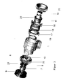
Fig. 3 shows a perspective, exploded representation of the
components of these locking means.
In the cross section of Fig. 1, an example of an operating assembly of
a security system according to the invention is represented. The operating
assembly has a profile with an outer contour of a eurocylinder. A bit 1 in a lock
housing 2 of the operating assembly, hereinafter also indicated as "the
eurocylinder", is not, as is customary, operable by a key, but by means of an
operating lip which is permanently present, while, in reaction to an
authorization code, this is coupled to the bit 1 with the aid of an
electromotor 3.
Apart from the locking means, the lock mechanism according to the
invention is built up symmetrically with the aid of the same parts on both
sides, while, independently of each other, operation from the inside as well as
from the outside of the door is possible. From the outside of the door, the
movement of the operating lip 29 is transmitted via a connecting strip 30 and
sprocket 31 to the axle 23 which is provided on both ends with a small
sprocket, one of which is in engagement with the sprocket 31 and the other one
with the sprocket 21 in Fig. 2. Sprocket 21 is identical to sprocket 31 and
therefore rotates perfectly synchronously with operating lip 29. Rerouting this
movement along the cylindrical part of the lock housing 2 leaves space in the
cylindrical part for accommodating a standard battery 36. From the inside of
the door, this movement is transmitted in the same manner to axle 24 and
sprocket 22 in Fig. 2.
In Figs. 2 and 3, the locking means are represented in more detail.
The electromotor 3, with built-in delay mechanism and built-on electronic
control module 4 is fitted in the lock housing 2 via ring 5 and is coupled to an
axle 6 on which a first cam disc 7 is non-rotatably mounted. The second cam
disc 8, which is provided with locking cams engaging in the cam ring 9
connected to the lock housing 2, slides over the axle 6 and is pushed against
first cam disc 7 with the aid of spring 10, while, in the position of rest as
drawn, the locking cams of the second cam disc 8 are in engagement with the
cam ring 9, so that rotation thereof in the lock housing 2 is not possible. At the
left hand side, the first cam disc 7 has a segment that rotates through an optic
switch 11 with which the blocking position, being the position of rest, is
detected. The remaining positions of the axle 6 are derived with the aid of the
control module 4, which detects the position of the rotor via Hall sensors and
can thus determine the position of the axle 6 relative to the position of rest.
Via the earlier-mentioned cams, which correspond with openings in
the bit 1, the second cam disc 8 is coupled to bit 1 and, as a result thereof, can
slide but cannot rotate relative to the bit 1. In this manner, in the position of
rest, the bit 1 too is locked relative to the lock housing 2. This locking of the bit
1 takes place at an angle which is greater than the minimal angle prescribed
in the Dutch NEN standard 5089 of 20 degrees relative to the central axis,
through the part of the lock profile projecting outside the cylindrical part
indicated in detail A-A in Fig. 1.
At the left hand side, bit 1 is also provided with a segment which
rotates in two optic switches 12, which are positioned at an angle of 90 degrees
relative to each other and with which the position of the bit 1 relative to the
lock housing 2 can be determined in four quadrants.
Apart from the first cam disc 7, on the axle 6, a sleeve with a curved
disc 13 is non-rotatably mounted, around which a sleeve 14 can slide, which is
provided with a pin 15 running in the curve of the curved disc 13. A pin 20,
attached in the motor housing, allows for the sleeve 14 to only slide and not
rotate relative to the lock housing 12.
Around the sleeve 14, two cam rings 16 and 17 rotate which, with
the aid of a spring 18, are pushed apart but with the aid of a spring ring 19,
are confined on a sleeve 14. The cams of these rings slide in corresponding
openings in bit 1 and hence cannot rotate but only slide relative to the bit 1.
For allowing the lock to be opened from the outside of the door, the
eurocylinder needs to be unlocked. To this end, the motor 3 rotates the axle 6
to the right through an angle of approximately 120 degrees, while,
successively, with the aid of the first cam disc 7, the second cam disc 8 is slid
out of locking and then, the sleeve 14 is slid to the right via the curved disc 13,
while cam ring 16 enters into engagement with the sprocket 21 which is also
provided with openings corresponding to these cams. Should the position be
such that the cams of cam ring 16 do not slide into the openings of sprocket 21,
then, the spring 18 is compressed.
If, thereupon, the operating lip 29 in Fig. 1 is pivoted and the cams
of cam ring 16 in Fig. 2 come to lie in front of the openings in sprocket 21,
then, under the pressure of the spring 18, the cam ring 16 still slides into these
openings and engagement occurs, whereupon the bit 1 can be moved by
turning the operating lip 29 which drives the sprocket 21 and the cam ring 16,
so that, manually or by a separate drive, the lock of the door can be opened or
closed or be turned to the night position.
When operating the unlocking of the lock from the inside of the door,
with the aid of electromotor 3, the axle 6 is turned to the left through an angle
of approximately 120 degrees, while, successively, in the same manner, with
the aid of first cam disc 7, second cam disc 8 is slid from locking and then,
sleeve 14 is slid to the left via curved disc 13, while cam ring 17 enters into
engagement with sprocket 22. Should the position be such that the cams of
cam ring 17 do not slide into the openings of sprocket 22, then, also, the spring
18 is compressed. If the operating lip at the inside of the door is then pivoted,
and the cams of cam ring 17 come to lie before the openings in the sprocket 22,
then, under pressure of the spring 18 the cam ring 17 still slides into these
openings and engagement occurs whereupon the bit 1 can be moved from the
inside of the door.
Operating the lock from the inside of the door is therefore completely
independent of operation from the outside of the door, while operation from the
inside has precedence over operation from the outside of the door. In this
manner, it is also possible to leave the lock from the inside of the door in a
daytime position, wherein the lock can be operated from within without
contactless chip card.
The lock mechanism is protected by two hardened discs 25 and 26 in
Fig. 2, so that it is not possible to drill out the lock out with the aid of a drill
and hence the anti drill security required according to the NEN 5089 standard
is provided for. Disc 25 also serves as seal of a battery holder 35 in which a
battery 36 is present. Changing the batteries can be done by disassembling the
cylinder from the lock housing and pivoting the battery holder upwards around
the pivot point 37 (see Fig. 1).
According to this example, the electronics of the electronic lock are
accommodated on different prints, the most important print 32 of which is
located in the space where in a conventional, mechanical lock, the feeler pins of
the key are located. On this print, a transmitter/receiver is present, arranged,
for instance, for receiving signals in the 868 MHz band which, with the aid of
antenna 39, has a range of approximately 20 meters and can communicate with
a similar transmitter/receiver accommodated in an adapter module (not shown)
which can be plugged into a socket and in which also a GSM modem has been
accommodated so that the authorization codes can be transmitted via a wireless
phone connection from, for instance, the care center to the electronic lock.
In the corresponding space at the other side of the cylinder, a print
is located with which the energy supply is regulated, while, in the case of
emptied batteries, via an external connection in opening 38, energy from
outside can be supplied.
Print 33, which is provided both at the outside and at the inside of
the door in the projecting part of the lock housing 2, contains a card reader for
reading a contactless chip card. Behind a small lens in opening 34, a bicolored
light emitting diode is arranged, with which information signals can be given
to the user.
Apart from locking and unlocking the operating assembly by blocking
or, conversely, releasing the movability of the bit 1 in Fig. 2, the motor 3 also
allows the bit to be locked in the position of rest at the prescribed angle, when
the bit, after a time delay, is controlled for bringing the locking means in the
locking position. To this end, an additional cam 27 is provided on the second
cam disc 8 and an additional cam 28 on curved disc 13. Should the second cam
disc 8 not slide into the locking position but remain on top of the cam ring 9 and
therefore in a position slid to the right, then, the cams 27 and 28 interlock and
the second cam disc 8, and hence the bit 1, are taken along by the curved disc 13
until second cam disc 8 can engage in the cam ring 9 and locking occurs, while
the bit 1 is at the prescribed minimal angle of 20 degrees relative to the central
axis through the part projecting outside the cylindrical part.
Apart from the use of a contactless chip card it is, naturally, also
possible to use a contactless label, for instance in the form of a key ring, or
built-in in a watch. The security can also be improved by using a so-called
"challenge/response" system, for instance according to the standard DES
protocol.
With the aid of the optic switches it is possible to detect the rotation
of the bit and hence determine in what position the lock is. Further, on the
print 32 in the part of the cylinder projecting outside the door, an infrared
transmitter and receiver are provided with which, together with a
retroreflective mirror on the inside of the door post, it is possible to detect
whether or not the door is closed. This information can also be transmitted via
the 868 MHz transmitter/receiver to the central authorization system.
Apart from being operated with the aid of the contactless chip card,
the lock can also be operated via the contactless transmitter/receiver in the
868 MHz band. With this, it is possible to make a remote control with which,
for instance, a patient can open the door from a distance.