Background of the Invention
It is known that the stability of a person is a function of the posture of the
person's body. The weight line is an imaginary line through which the center of
gravity of the person's body projects into the ground. The stability of the knee is
directly relational to the distance between the weight line and the knee axis. In
the prosthetic knee devices stability is accomplished when the center of gravity and
the weight line passing therethrough are placed anterior to the knee center, at the
greatest possible distance therebetween. However, typically, the dynamics and the
structure of prosthetic knee cages force the knee center to be maintained posterior
relative to the weight line. The knee cages of the prior art, while trying to
accomplish stability, typically provide a relatively minor degree of adjustments of
the center of gravity and weight line of a patient relative to the pivotal axis of the
cage. Significantly, the knee cage of the invention provides the ability to
manipulate and position the weight line anterior to the knee center. To assure
stability the knee cage of the invention utilizes a simple system that allows the
knee unit to effectively shift the weight line up to four inches anterior or posterior
relative to the center of rotation of the knee axis.
The terminal impact is known to be the resultant force generated during
the swinging motion of a lower limb and an upper limb with respect to each other,
when the prosthetic leg reaches the end of its swing phase, prior to achieving a
substantially straight position. When humans advance in the walking cycle, a leg
bends at the knee and is lifted above the ground. In order to be supported by the
ground again, the leg has to be fully extended. Prosthetic legs operate in a similar
manner. If the motion of the prosthetic lower limb caused by the forces of the
terminal impact is not decelerated, a very revealing and often embarrassing noise is
produced. To the discomfort of a patient, this makes the presence of the
prosthesis very obvious, causing other people to be aware that the patient has an
artificial leg. The terminal impact also negatively affects the structural elements of
the prosthetic device itself, often leading to their damage. Thus, there is strong
necessity of minimizing the effect of the terminal impact.
Another negative aspect of the prior art prosthetic devices is the artificially
high rate at which the leg advances during the swing phase to its complete straight
position. In the prosthetic devices, in the process of reaching the stop in full
extension, an undesirable momentum of forces develops which has to be
minimized. If this does not occur, one part of the leg will crash against the other
part of the leg. Therefore, there is an obvious need for a prosthetic device capable
of regulating and decelerating its motion during the swing phase before it reaches a
substantially straight position. The prosthetic device of the invention closely
simulates the movement of human limbs, without being subjected to the results of
the terminal impact. It moves rapidly in the initial stages of extension, and then
slows down before reaching the stop in full extension.
Summary Of The Invention
One aspect of the invention provides a prosthetic knee cage comprising a
base unit formed by spaced from each other first and second side members
interconnected by a connecting element, so as to form an operational channel
therebetween. The platform is adapted for pivotal cooperation with the base unit.
The adjustment device is provided for adjustment of pivotal movement of the
platform relative to the base unit. The adjustment device is situated within an
interior proximal region of the base unit and includes a support bar movably
arranged relative to the anterior proximal region of the base unit. The adjustment
device further includes a support element interconnecting anterior proximal
regions of the first and second side members. The support bar is adapted to
receive a resilient member.
As to another aspect of the invention, position of the support bar relative to
the support element is adjusted by means of adjustment members adapted for
threadable engagement with the support bar. Position of the support bar and
resilient member relative to the support element can be adjusted by means of
rotation of the threadable members within the support element.
As to a further aspect of the invention, the platform consists of a
substantially flat table with first and second side plates spaced from each other and
extending downwardly therefrom. The platform is formed with an anterior and
posterior pivotal mount units separated by the pivotal axle.
An important feature of the invention is that the pivotal axle of the platform
is placed well posterior within the structure of the knee cage. Forward or anterior
movement of the platform can be adjusted through the use of the adjustment
mechanism. Thus, as the platform is allowed to tilt further in the anterior
direction, the attached socket including a limb member therefore is placed in a
further extended position relative to the pivotal axle. This brings the gravity
center of a patient body even further in the anterior direction relative to the pivotal
axle.
The preferred embodiment of the knee cage allows for approximately
between 20° to 30° of angular adjustment of the platform. Position of the
platform perpendicular to the center of gravity is a neutral position. The support
bar or stop of the adjustment device can be lowered, so that the platform can
achieve inclination or tilt of about 10° - 15° from the horizontal in the anterior
direction. In adjusting the platform of the cage in this manner, the weight line
passing through the gravity center of a body is allowed to be shifted in the anterior
direction relative to the knee center, therefore making the cage and prosthetic knee
of the invention inherently stable, just by manipulating the weight line. This
occurs without using any locking mechanisms that are dependent upon the system
of hydraulics.
As to still another aspect of the invention, a prosthetic device is provided
comprising an upper prosthetic limb member, a lower prosthetic limb member, a
hydraulic cylinder and a gas cylinder independent from said hydraulic cylinder.
The hydraulic cylinder has a hydraulic piston movably disposed thereinside so as
to form a hydraulic chamber between an interior of the hydraulic cylinder and the
hydraulic piston. A first connecting element extends outwardly from the hydraulic
piston. A gas cylinder is also provided having a gas piston movably disposed
thereinside, so as to form a gas chamber between an interior of the gas cylinder
and the gas piston. A second connecting element extends outwardly from the gas
piston. The first and second connecting elements are movably associated with the
upper prosthetic limb member, in such a manner that the hydraulic and gas
chambers are responsive to operation of the prosthetic leg.
As to a still further aspect of the invention, there is a valve arrangement
associated with the gas chamber. Movement of the hydraulic piston toward the
lower prosthetic limb member results in expansion of the gas chamber, causing the
gas entering the gas chamber through the valve gas arrangement. Upon
movement of the hydraulic piston away from said lower prosthetic limb member
the gas piston is directed toward the lower prosthetic limb member diminishing the
gas chamber. This motion is resulted in compression and discharging the gas
from the gas chamber through the gas valve arrangement.
As to still another aspect of the invention, a pressure generated by a
resilient bladder forces the hydraulic fluid into the hydraulic cylinder causing
motion of the hydraulic piston toward the upper prosthetic member and motion of
the gas piston toward the lower prosthetic limb member.
As to a still further aspect of the invention, a pivotal platform is interposed
between the upper prosthetic limb member, the hydraulic cylinder and the gas
cylinder in such a manner that the first and second connecting elements are
pivotally connected to the platform. The platform is pivotal about a pivotal axle
situated within a central region of the device. The second connecting element is
pivotally connected to the platform through an anterior pivotal mount disposed
anterior to the pivotal axle, whereas the first connecting element is pivotally
connected to the platform by means of a posterior pivot mount disposed posterior
to the pivotal axle.
Brief Description Of The Drawings
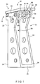
FIG. 1 is a semi-perspective view of an adjustable prosthetic knee cage
having a pivotal platform adapted to accommodate in line piston arrangement;
FIG. 2 is another perspective view thereof;
FIG. 3 is an exploded perspective view thereof;
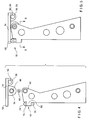
FIG. 4 is a side elevational exploded view thereof;
FIG. 5 is a side elevational assembled view thereof;
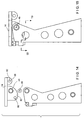
FIG. 6 shows the adjustable knee cage of FIGs. 1-5 in an anterior tilt
position;
FIG. 7 shows the adjustable knee cage of FIGS 1-5 in a posterior tilt
condition;
FIG. 8 is a front elevational view of the adjustable knee cage of FIGs. 1-5;
FIG. 9 is a section view according to section line 9-9 of FIG. 5;
FIG. 10 is a section view according to section line 10-10 of FIG. 8;
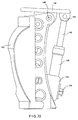
FIG. 11 is a semi-perspective view showing an adjustable knee cage having
a pivotal platform adapted to accommodate a dual piston arrangement;
FIG. 12 is another semi-perspective view thereof;
FIG. 13 shows a semi-perspective exploded view thereof;
FIG. 14 is a side elevational exploded view thereof;
FIG. 15 a side elevational view showing a neutral position of the platform;
FIG. 16 is a side elevational view showing anterior tilt of the platform;
FIG. 16A is a schematic view illustrating application of the principles of the
invention;
FIG. 16B is another schematic view illustrating principles of the invention;
FIG. 16C is a view illustrating another embodiment of the invention;
FIG. 16D is a diagram illustrating principles of the invention;
FIG. 16E is another diagram illustrating principles of the invention;
FIG. 17 is a side elevational view showing posterior tilt of the platform;
FIG. 18 is a front elevational view of the adjustable knee cage of Figures
11- 15;
FIG. 19 is a section view according to section line 19-19 of Figure 15;
Figure 20 is a section view according to section line 20-20 of Figure 18.
FIG. 21 is a diagrammatic representation generally illustrating an above-knee
prosthetic leg incorporating the prosthetic knee cage and a knee device of the
invention;
FIG. 22 is one side elevational view of the prosthetic knee device of the
invention;
FIG. 23 is another side elevational view of the prosthetic knee device;
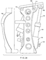
FIG. 24 is a further side elevational view of the prosthetic knee device
showing a cover being removed;
FIG. 25 is a partial section view showing one position of the prosthetic knee
device;
FIG. 26 is a partial section view showing another position of the prosthetic
knee device;
[044] FIG. 27 is a partial section view showing a further position of the prosthetic
knee device;
FIG. 28 is a rear elevation view of the prosthetic knee device;
FIG. 29 is a front elevational view of the prosthetic knee device; and
FIG. 30 is a partial sectional view showing in line prosthetic knee device in
combination with the knee cage of the invention.
Description Of The Preferred Embodiment
Turning now to Figs. 1-10 illustrating a first embodiment of the adjustable
prosthetic knee cage of the invention. The knee cage 10 typically consists of a
base unit 12, a platform 14 and an adjustment mechanism 16. The adjustment
mechanism 16 is located at a front or anterior region of the cage with the apertures
42, 44 situated at a rear or posterior region thereof. A U-shaped base unit 12 is
formed by spaced from each other first side member 22 and a second side member
24 which are interconnected by a connecting element 26, so as to form an
operational channel 28 therebetween. In the preferred embodiment of the
invention the first and second side members 22, 24 are in the form of substantially
flat plates extending between their respective distal parts 32 and 34 and proximal
parts 36 and 38. Pivoting apertures 42, 44 are formed within the proximal region
of each side member, so as to receive an axle 46 providing a pivotal connection
between the base unit 12 and the platform 14. The pivotal apertures 42, 44 and
the axle 46 are situated well posterior within the cage. In the assembled condition
of the knee cage the pivotal axle 46 passes through the bearing unit accommodated
by the pivotal apertures 42 and 44 and also passes through bearings formed within
respective pivotal openings 48, 49 of the platform 14.
The platform 14 is adapted for movable cooperation with a proximal region
of the base unit 12 and consists of a substantially flat top table 52 with first and
second side plates 54 and 56 extending downwardly therefrom. In the preferred
embodiment of the invention, the side plates 54, 56 are substantially flat and
spaced from each other so as to be adapted for pivotal motion substantially within
the proximal region of the operational channel 28 in the vicinity of the inner
surfaces of the proximal parts 36 and 38 of the respective first side member 22 and
the second side member 24. Upon the platform 14 being properly received within
the operational channel 28, the pivoting apertures 42, 44 and the pivoting openings
48, 49 are adapted for passage of the pivotal axle 46 therethrough.
The platform of the adjustable prosthetic knee cage illustrated in Figures 1-10
is formed with a single pivot mounting unit 65 which is adapted to pivotally
receive a single connecting rod of the prosthetic knee unit. The pivotal mounting
unit 65 includes a mounting recess 67 formed within the posterior rear region of
the platform 14 and spaced from each other by the mounting recess 67 the first
and second supporting elements 58, 59 which extend outwardly from the bottom
posterior area of the platform 14. As will be discussed later in the application,
one connecting element or piston rod of the prosthetic knee unit is adapted to be
received within recess 67, between the first and second supporting elements 58 and
59. In this manner a pivotal member passes through the apertures 62 and 64
formed within the respective supporting elements, so as to pivotally accommodate
the connecting element therebetween.
The embodiment of the adjustable prosthetic knee cage illustrated in
Figures 11-20 is in many respects similar to the previously discussed embodiment
of FIGs. 1-10. However, as best illustrated in at least Figures 13, 14 and 20, the
platform 14, in addition to the posterior mounting unit 65 is formed with an
anterior mounting unit 80, which includes anterior supporting elements 82 and 84
extending outwardly from the bottom area of the platform 14. The central regions
of the anterior supporting elements 82 and 84 are formed with pivoting openings
48 and 49 respectively adapted for passage of the pivotal axle 46. The anterior
region of the anterior supporting elements is formed with apertures 86 and 87
adapted to receive the respective pivotal member. In operation a space 88 between
the anterior supporting elements 82 and 84 is adapted to pivotally accommodate
another connecting element or piston rod of the prosthetic knee. It will be
discussed later in the application that in the fully assembled condition of the
prosthetic knee, the platform 14 is supported by the axle 46 and is pivotally mobile
with respect to the side members 22 and 24. Furthermore, one piston rod is
pivotally accommodated within the posterior mounting unit 65 between the
posterior supporting elements 58 and 59, whereas another piston rod is pivotally
accommodated within the space 88 of the anterior mounting unit 80 between the
anterior supporting units 58 and 59.
Mounting holes can be provided within the table 52 and connecting element
26 which are adapted to accept existing components which are common in the
prosthetic industry.
An adjustment mechanism 16 is situated in the anterior proximal region of
the knee cage and consists of a support bar 72 or a stop which is movably arranged
with respect to the support element 66 interconnecting the anterior proximal
regions of the first and second side members 22 and 24. The support bar 72 is
adapted to receive a resilient member 74. Position of the support bar 72 with
respect to the support element 66 is adjusted by means of adjustment elements 76
and 78. In the preferred embodiment of the invention the adjustment elements 76
and 78 are in the form of threadable members or screws. Thus, the position of the
support bar 72 and the resilient member 74 can be adjusted by means of rotation of
the threadable elements 76 and 78. As the threadable members are turned in one
direction the support bar 72 is elevated with respect to the base unit 12 in general
and specifically with respect to the support element 66. In this position the
downward motion of the anterior portion of the adjustable platform 14 in general,
and the table 52 in particular, is restricted.
Although the adjustment mechanism utilizing the threadable adjustment
elements 76 and 78 have been described hereinabove, it should be understood that
the adjustment mechanism utilizing any conventional means of elevating or
lowering the support bar 72 with respect to the support element 66 is within the
scope of the invention.
In operation of the knee cage, upon elevation of the support bar 72 by the
adjustment mechanism 16 the platform 14 including the table 52 is prevented from
reaching its full downward position. Thus, the slant of the platform 14 is
regulated by the height or elevation of the bar 72 and resilient member 74. The
reason for the anterior tilt or the over center nature of the cage is as follows. As
the knee is brought to full extension because of the placement of the foot, there is a
moment of instability when the knee is fully extended and not being controlled by
the prosthetic knee mechanism itself. In the invention, the knee cage 10 allows
the knee to become stable by allowing the weight line passing through the gravity
center of a person's body to be brought well anterior to the location of the pivotal
axle 46. If the platform 14 including the table 52 is allowed to go beyond the
horizontal level (see FIGs. 5 and 15) and to reach an anterior slanting position (see
FIGs. 6 and 16), the weight line passing through the gravity center of a person's
body is moved even further in the anterior direction relative to the axle 46. By
moving the weight line and the gravity center of a person's body anterior to the
axle 46, the invention prevents the knee cage from folding backwards, or to go into
the flexion. This position is named hyper-extension. In the extension, the
anterior sloping position of the platform 14 is achieved (see FIGs. 6 and 16),
rendering the knee to become stable. This is because, the weight line is situated to
be anterior to the location of the axle 46. The invention allows to place the weight
line passing through the gravity center of a person's body to be anterior to the
pivotal axle 46 of the knee cage. The more anterior the center of gravity is
brought relative to the axle 46, the more stable the prosthetic knee becomes. This
aspect of the invention is more specifically illustrated in FIGs. 16A and 16B in
which the axis C-C passes through a pivotal axle 46 and the weight line D-D
passes through the gravitational center G of a person's body. Referring now to
FIG. 16A, illustrating a vertical orientation of a body with substantially horizontal
position of the platform 14. In this instance the distance E between the axis C-C
and the weight line D-D is relatively small. However, when the body moves
forward, as illustrated in FIG. 16B, the gravity center G and the weight line D-D
moves further in the anterior direction from the axis C-C. This move is reflected
in the increased distance E, indicating that the weight line is shifted anterior to the
pivotal axle 46.
Another feature of the invention is illustrated in FIG. 16C, which is
applicable when a patient is not able to have enough hip extension to
accommodate anterior slanting position or forward inclination from a horizontal
position. In such instance, a wedge-shaped member 90 can be interposed between
the platform 14 and the socket 12. The member 90 allows the patient's limb to
become oriented substantially horizontally or at the angle of 180° relative to the
ground, while also allowing the platform 14 to assume the beneficial anterior
inclination.
There are situations where the center of gravity of a patient's body is not
significantly shifted in the anterior direction relative to the axis of rotation or axle
46 because of the orientation of the center of gravity being closer to the center of
rotation of the platform 14. The advantage gained by having the anterior
inclination of the platform 14 can offset the inability of bringing the weight line
anterior. This occurs in view of the increasing the amount of torque necessary to
reach the null point. Considering how much energy it takes to move a certain
mass at a certain fulcrum distance from that mass, if the mass must be moved in an
arc moment in relation to the fulcrum, it may be necessary to move the tilted
version of the platform about 105°, where the movement at the level version with
the platform being parallel to the ground, it takes only about 90°. Referring now
to FIG. 16D, where we can see the resting point F' to the null point of 105° in
relation to the axis or the center of rotation of the unit. In FIG. 16E shows the
axis being at a level with the center of rotation, rotating to 90° before the null point
N is reached in relation to the axle or center of rotation.
The center of gravity of a person's body is located at approximately lumbar
to at or about the height of the navel. The center of rotation as illustrated in FIGs.
16D and 16E passes through the axle 46. When the socket is placed at a level
attitude in relation to the ground with the knee unit at a level position, it is possible
to gain as much as 1.5" in terms of the anterior shifting of the center of gravity in
relation to the center of rotation or axle 46. In dealing with manipulating the
weight line passing through the gravity center, when the tilt of the platform is
forced to an anterior position, the center of gravity is forced to be in a more
anterior or forward position. This, brings the weight line anterior to the center of
rotation or axle 46 by an increase factor.
Raising or lowering the support bar or stop 72 of the knee cage allows the
prosthetic knee to flex beyond 180° or less than 180°. When the flexion is
beyond 180° or when the anterior slanting position is reached, additional stability
is insured. On the other hand, when the flexion is less than 180°, or the posterior
slanting position is accomplished, the controlled position of the knee unit is
insured. This condition might be desirable for some patients having extremely
long limbs. In the elderly population, and in the majority of the amputee
population, increased stability not only becomes desirable for safety, but it is also
necessary to insure that these patients do not fall. Some patients have knee
flexion contractures. This occurs due to shortening of the ligemental structures
and the tendon structures in their leg, causing the patients to have less than full
extension, in terms of their hip flexing muscles. In the invention this condition
can be accommodated by adjusting the knee cage in such a way so as to
accommodate the knee flexion contracture. The stability of a patient can be
maintained by adjusting the ankle of the tibia in relation to the foot. This brings
the weight line anterior in relation to the femoral socket or the trans-femoral socket
in relation to the center of gravity of the body.
Although the knee cage of the invention is described with reference to
specific prosthetic knee units, it should be noted that the prosthetic knee cage of
the invention is not limited to applications with the discussed knee systems. The
knee cage can be used with other prosthetic knee systems, as long as such systems
fit into the confinement of the elements of the cage.
Referring now to FIG. 21, illustrating the above-knee prosthetic leg which
includes the prosthetic knee cage and the prosthetic knee. The prosthetic leg is
designated generally by the numeral 120 and includes a socket or an upper
prosthetic limb member 112 adapted for receiving a leg stump 111 of an amputee.
The socket 112 is coupled by a conventional arrangement to an adjustable platform
114 provided at the top portion of the knee cage 110, which can be provided with a
removable cover 142. As it has been discussed substantially in this application,
the platform 114 is adapted for pivotal motion relative to the base of the cage. A
pylon 117 at one end is coupled to the bottom of a knee cage 110 and at the other
end is coupled to a prosthetic foot 119. The pylon 117 and prosthetic foot 119
define a lower prosthetic limb member 120.
The prosthetic knee assembly of the invention is positioned within the
cage 110 and consists of a double cylinder arrangement 122 and a control valve-bladder
sub-assembly 124, etc. These elements form a part of independent from
each other a hydraulic system 121 and a pneumatic system 123. With respect to the
connection with the platform 114, a gas or air cylinder unit 128 and a hydraulic
cylinder unit 126 are arranged tandemly on either side of the axle 146 of the
prosthetic knee cage 110.
The hydraulic system 121 includes a main body 130 adapted to receive a
bladder 132 and a cam valve 134 operationally connected to the hydraulic cylinder
126. A cartridge check valve 135 is situated within the main body directly below
the output region of the hydraulic cylinder. As best illustrated in FIGs. 25, 26 and
27, the hydraulic cylinder 126 is formed by a substantially cylindrical wall 125
having an inner surface 127 and contains therein a piston 136 which is displaced
by a suitable fluid which may be, for purposes of illustration, a silicone oil. A
hydraulic chamber 140 is formed within the inner space of the cylinder 126
between its bottom and the piston 136. A first connecting element or hydraulic
piston rod 138 at one end attached to the piston 136, and at the other end is
pivotally connected to the platform 114 of the cage at the posterior pivot mounting
165. The main body 130 is coupled to the cylinder 126 and supports a flow
control valve.
The main body 130 is also formed with a chamber adapted to receive a
substantially horizontally disposed rotary cam valve which is sealed around its
outer most circumference by a lip seal.
The pneumatic system 123 includes the gas cylinder unit 128 which is
formed with a substantially cylindrical housing 129 having at least an interior
surface 131, with the gas piston 133 movably position thereinside. A second
connecting element or gas piston rod 137 is at one end thereof pivotally connected
to the platform 114 of the cage at an anterior pivotal mount 180, whereas the other
end is attached to the piston 133. A gas chamber 139 is formed within the inner
space of the gas cylinder 128 between the bottom portion of the cylinder and the
piston 133.
One of the main functions of the pneumatic system 123 including the gas
cylinder 128 is to minimize the effect of the terminal impact and to slow down
motion of the leg during swing phase. As best illustrated in FIGs. 25-27, the gas
cylinder 128 is movably and/or pivotally coupled to the main body 130 of the
hydraulic unit via a mounting arrangement which includes mounting plates 143
positioned on either side of the main body.
The dual piston arrangement is pivotally associated with the knee cage
assembly previously described with respect to Figures 11- 20. It is best illustrated
in at least FIGs. 25- 27 that the gas piston rod 137 is pivotally connected through
the anterior pivot mount 180 which is disposed anterior and below the central
pivotal axle 146. On the other hand, the hydraulic piston rod 138 is pivotally
connected to the posterior pivot mount 165 which is disposed posterior and above
the central pivotal axle 146. As discussed hereinabove, the platform 114 is
pivotally supported by the central pivotal axle 146 within the base of the knee
cage.
A valve arrangement or gas valve 141 is disposed within the wall of the
gas cylinder 128, so as to provide communication between the gas chamber 139
and outside environment. In the preferred embodiment of the invention an
ambient air is used for the operation of the gas cylinder 128. Nevertheless, it
should be noted that utilization of any suitable gas for the same purpose is also
contemplated. The valve arrangement 141 can be adjusted to regulate flow of gas
out of the gas chamber 139. During movement of the gas piston 133 in one
direction the gas valve arrangement 141 is adapted to controllably discharge the
gas accumulated within the gas chamber 139, whereas during the movement of the
piston 133 in the opposite direction it operates as a check valve introducing air or
gas into the expanding gas chamber.
The prosthetic knee of the invention is capable of achieving approximately
a 126° angle in the movement between the fully flexed position to the fully
extended position. The fully flexed position, as illustrated in FIG. 27, corresponds
to the situation where the knee is folded or a patient achieving a kneeling position
in which the gas chamber 139 is filled with gas. As the prosthetic knee moves
from the fully flexed position to the fully extended position (see FIGs. 26 and 27)
the gas trapped within the gas chamber is controllably discharged by means of the
gas valve 141 regulating the speed and intensity of the extension cycle.
Operation of the check valve 135 and the rotary cam 134 do not form an
essential part of the hydraulic system and have been in full detail disclosed by U.S.
Patent 5,779,735 which the present application incorporates by reference. Similar
to the prosthetic knee disclosed by U.S. Patent 5,779,735, a bladder membrane 132
is situated within the bladder chamber 150 which includes a bladder valve 152.
The valve 152 is adjustable for varying bladder compression, flexion resistance
and extension drive. The bladder 132 is affected by the operation of valves situated
within the main body 130, so as to be compressed for storing all of the required
energy. The bladder is capable of storing the kinetic energy for the return cycle or
the upward motion of the hydraulic piston 136. This enables the hydraulic fluid to
be moved from the accumulation bladder chamber 150 into the hydraulic chamber
140 to have the required resistance within the cylinder 126 when the bladder
collapses. Such action accumulates and stores the kinetic energy required for the
operation of the knee unit of the invention.
An accumulation chamber 150 accommodates the displaced oil. As the oil
is displaced during a compression stroke, pressure is exerted on the bladder
membrane 132 allowing it to compress the gas situated thereinside and accept the
displaced oil. Pressure is increased on the inner area of the bladder membrane
132, thus storing enough kinetic energy to power the return cycle and return of the
piston 136 to the extended position. The air valve 152 communicating with the
airside of the bladder chamber can adjust the level of kinetic energy. The force
necessary to compress and extend the piston 136 and piston rod or connecting
element 138 is adjustable by increasing or decreasing the amount of air pressure in
the bladder cylinder 150. During operation of the knee the kinetic energy is
stored in the bladder capable of driving the piston 136.
A cartridge-type ball check valve 135 is placed between the hydraulic
chamber 140 and the bladder chamber 150. To stop the flow of fluid from the
cylinder 126 to the bladder chamber 150 a rotary cam 134 associated with the ball
check valve 135 is provided. As the cam is rotated, the ball is lifted or lowered
into the ball seat either allowing or not allowing passage of fluid through the ball
seat to the accumulation chamber. Free oil flow is allowed back into the cylinder
126 due to the kinetic energy stored in the compressed air/gas in the bladder
chamber 150 pushing on the bladder 132 to return the oil to the hydraulic chamber
140 through the check valve 135 to the cylinder returning the cylinder to the
extended position.
The hydraulic chamber 140 is pressurized through the downward motion of
the piston 136, so as to allow the hydraulic fluid to pass through the cartridge valve
135 only when the cam lobe is in a position to lift the ball out of its seated position
in the cartridge valve 135, thereby allowing fluid to pass around the cam. As the
fluid passes around the cam when the cam is in the open position, the hydraulic
fluid then enters through an orifice in the back of the cam chamber. Through that
orifice the hydraulic fluid is allowed to pass through the hole just posterior to the
cam housing into an accumulated chamber. The valve 135 situated above the
cam also operates as a check valve. This means that it has a spring associated with
the ball valve mechanism. Thus, as the pressure on the bladder side of the valve
135 is greater than the pressure on the cylinder side, the bladder pressure pushes
the fluid past the ball valve 135 back into the cylinder 126 returning the plunger
136 and the rod 138 to their original extended position.
In operation, as the platform 114 of the knee cage is allowed to pivot
posteriorly or downwardly, as illustrated by the arrow A in FIGs. 26 and 27, the
hydraulic rod 138 and the hydraulic piston 136 are moved compressing the fluid
and enabling passage thereof through the channels of the main body 130, so as to
compress the bladder 132. In this situation the gas piston 133 reaches fully
extended and the hydraulic piston 136 is retracted (see FIG. 27). After the finish
of the gait cycle and during swing phase, the accumulated kinetic energy in the
bladder 132 acts to return the piston 136 of the hydraulic cylinder to its extended
position. In this motion the hydraulic rod 138 and the platform 114 of the knee
cage are returned to their original position. If this motion is not properly
controlled, it occurs too fast resulted in a loud sound of engaging mating surfaces.
The gas cylinder 128 provided with the adjustable valve mechanism 141 which
controllably discharges the gas out of the gas chamber 139 into the atmosphere.
This arrangement prevents this undesirable action and regulates the speed of the
swing phase and the terminal impact. The amount of generated kinetic energy
can be adjusted by means of the gas valve 152 associated with the bladder. If more
extension is needed, the gas pressure in the bladder 132 should be increased. The
normal operating pressure inside the bladder is between 60 and 150 pounds,
according to the activity level of the patient.
To summarize the above, as the kinetic energy generated by the
compression of the bladder 132 forces the fluid into the hydraulic chamber 140
causing the hydraulic piston 136 to be pushed outward or toward the upper
prosthetic limb member, resulted in the pivotal motion of the platform 114 of the
knee cage upward (as illustrated by the arrow B in FIG. 25). This motion places
the gas piston 133 into a retracted or downward position, causing compression of
the gas in the gas cylinder 128. Significantly, initially during the downward
motion of the piston 133 the gas is pressurized in the gas chamber 139. This
occurs in view of the compressible nature of the gas. As the gas or air is being
further compressed, the restrictive forces make it more difficult for the piston 133
to reach the bottom of the gas cylinder 128, resulted in minimizing the terminal
impact. The adjustable bleeding nature of the gas valve 141 positioned at the
bottom of the gas cylinder 128 is capable of releasing air in a controlled fashion,
and to inhibit the rapid and uncontrolled return of the prosthetic knee and the
platform of the knee cage to its most forward or downward position. In this
manner, a resultant damaging force and loud noise are minimized or completely
eliminated.
The adjustable prosthetic knee cage which was previously described with
reference to FIGs. 1-20 is also adaptable for use with the prosthetic knee having an
in line piston arrangement. The structure and operation of this prosthetic knee do
not form as essential part of the invention and have been in full detail disclosed by
the U.S. patent application S.N 10/278,361 filed October 23,2002, which this
application incorporates by reference. Similar to the prosthetic knee having the
dual piston arrangement previously discussed with reference to FIGs. 21-29, as
illustrated in FIG. 30 the in line piston arrangement also includes a multi piston
structure which is movably connected to the platform 214 of the cage by a single
pivot mount 224, which is situated in the platform 214 posterior to the central axle
246.
In the prosthetic knee having the in line piston arrangement a gas piston
cylinder 262 is provided outside the hydraulic cylinder 232. The bottom of a gas
cylinder 262 is formed with an upwardly facing lip edge 266. The cap 270 seals
the hydraulic cylinder 232 and also traps the gas between that seal and the bottom
portion of the concentric gas plunger 272. A closing cap 228 is provided at the
top of the gas cylinder 262, so as to fixedly receive the piston rod 226 which
extends between the pivot mount 224 and the hydraulic piston 234. As the
platform 214 of the knee cage is moved downwardly, the piston 234 pushes the
hydraulic fluid through the system in a manner discussed hereinabove. In this
motion, in view of the permanent connection between the piston rod 226 and the
gas cylinder 262, the gas chamber 268 is also expanded. This is because the gas
cylinder 262 moves up and down in relation to a fixedly positioned gas plunger
272, 274 that is mounted on the cap 270 of the hydraulic unit. In this motion the
gas volume increases, as the platform 214 is tilted or moved downwardly. In this
action more gas enters the chamber 268 between the plunger 272, 274 and the
bottom portion 264 of the gas cylinder. When the unit is extended, as a result of
the kinetic energy stored in the bladder 240, the gas accumulated in the chamber
268 is being compressed. In this manner, as the platform 214 of the cage returns
to its normal position, the bottom portion 264 compresses the gas against the
plunger 272 and traps gas therebetween. As the distance between the bottom
portion 264 and plunger 272 decreases, gas is gradually and substantially
pressurized. The pressurized gas slows down the swing phase, damping the
terminal impact. A gas valve 276 is provided at a lower portion of the gas
cylinder 260. As the gas is compressed in the chamber 268, it is allowed to escape
through the valve 276. During the initial stages of the swing phase, gas is
compressed rapidly in the chamber 268 until the pressure reaches a point where it
cannot be compressed rapidly. During the slow rate of compression gas is
allowed to escape through the valve 276 and therefore damping swing phase. This
arrangement minimizes or eliminates terminal impact, so that there is a proper rate
of return for the distal portion of the leg. The gas in the form of air is used as a
medium because initial compression is easy until the pressure builds up and the
last portion of the travel becomes more difficult. This occurs when the maximum
amount of damping power is needed just before the leg becomes fully extended, so
that it does not advance too rapidly without causing a resultant klunk.
As indicated hereinabove, the in line piston arrangement of the prosthetic
knee is adapted for cooperation with the knee cage which has been previously
discussed with reference to Figures 1-10. As best illustrated in Figure 30, the
piston rod 226 by means of the pivotal member 240 is movably connected to the
posterior mounting unit 265. The free end of the piston rod 226 is received within
the mounting recess 259 between two posterior mounting plates.
The knee cage of the invention adapted for cooperation with the in line
system illustrated in FIG. 30 operates in a manner similar to that used with the dual
piston arrangement of FIGs. 21-29. As the prosthetic knee cage interacts with the
forces that are initiated by the return of the hydraulic fluid into the cylinder 232,
the platform 214 is moved to an upward or substantially horizontal or anteriorly
tilted position. When the platform 214 is tilted anterior the knee center can be
manipulated to be considerably posterior to the center of gravity of a patient.
When the platform 214 is in a level position, the weight of a patient travels
approximately ½ to ¾ of an inch anterior to the central axle 246 promoting
stability. However, when the platform has an anterior tilt as much as 5 inches of
travel can be achieved anterior to the axle promoting extreme stability.
Actuation of the cam valve 134 in the prosthetic knee of the invention is
associated with at least one of the following three modalities. One mode of
operation is mechanical in nature and operates by providing a connector or cable
147 between the prosthetic knee and a movable ankle or foot 119 (see FIG. 21).
When the foot is in planter flexion or when the ankle position allows planter
flexion of the foot, the connector or cable 147 pulls on the lever or arm 145 which
locks the cam valve 134 into a closed position preventing flexion of the knee. As
the leg is brought into a vertical position, the cam valve 134 is placed into an open
position, thereby allowing the flow of fluid from the hydraulic cylinder 126 into
the bladder chamber 150.
The prosthetic knee of the invention is also adaptable for operation in the
electro-mechanical mode, whereby a switch located on the plantar surface of the
foot or the bottom surface of the foot can be activated. Such activation elicits a
response from a survo to pull the arm 145 into a position in which the foot contacts
the floor. The cam valve 45 is allowed to be placed into a position facilitating the
drop of the ball into the seat, so as to seal the unit. Such action prevents flow of
the fluid through the prosthetic knee leading to complete stoppage of the
flexionability of the knee.
A further mode of controlling the knee is by means of myoelectric control.
In this mode a signal from the residual musculature, or an electronic signal from
the brain of a patient to the residual musculature is amplified and sent to a
discriminator circuit. There the signal is analyzed to define the type of signal in
terms of its amplitude and duration. After that another discrimination step can be
conducted to define a selected response mode or activity such as walking, climbing
stairs, descending stairs, seating, etc. The proper placement of the cam valve 134
is elicited by an arrangement utilizing a signal from the discriminator circuit. This
provides a measured travel, so as to place the cam valve 134 in a desired position,
in order to coincide with the motion that is elicited by the brain. This is necessary
to achieve one of the previously discussed activities.