EP1415857A2 - Vehicle steering wheel - Google Patents
Vehicle steering wheel Download PDFInfo
- Publication number
- EP1415857A2 EP1415857A2 EP20030022977 EP03022977A EP1415857A2 EP 1415857 A2 EP1415857 A2 EP 1415857A2 EP 20030022977 EP20030022977 EP 20030022977 EP 03022977 A EP03022977 A EP 03022977A EP 1415857 A2 EP1415857 A2 EP 1415857A2
- Authority
- EP
- European Patent Office
- Prior art keywords
- switch
- steering wheel
- vehicle steering
- carrier
- actuating
- Prior art date
- Legal status (The legal status is an assumption and is not a legal conclusion. Google has not performed a legal analysis and makes no representation as to the accuracy of the status listed.)
- Withdrawn
Links
Images


Classifications
-
- B—PERFORMING OPERATIONS; TRANSPORTING
- B60—VEHICLES IN GENERAL
- B60R—VEHICLES, VEHICLE FITTINGS, OR VEHICLE PARTS, NOT OTHERWISE PROVIDED FOR
- B60R21/00—Arrangements or fittings on vehicles for protecting or preventing injuries to occupants or pedestrians in case of accidents or other traffic risks
- B60R21/02—Occupant safety arrangements or fittings, e.g. crash pads
- B60R21/16—Inflatable occupant restraints or confinements designed to inflate upon impact or impending impact, e.g. air bags
- B60R21/20—Arrangements for storing inflatable members in their non-use or deflated condition; Arrangement or mounting of air bag modules or components
- B60R21/203—Arrangements for storing inflatable members in their non-use or deflated condition; Arrangement or mounting of air bag modules or components in steering wheels or steering columns
- B60R21/2035—Arrangements for storing inflatable members in their non-use or deflated condition; Arrangement or mounting of air bag modules or components in steering wheels or steering columns using modules containing inflator, bag and cover attachable to the steering wheel as a complete sub-unit
- B60R21/2037—Arrangements for storing inflatable members in their non-use or deflated condition; Arrangement or mounting of air bag modules or components in steering wheels or steering columns using modules containing inflator, bag and cover attachable to the steering wheel as a complete sub-unit the module or a major component thereof being yieldably mounted, e.g. for actuating the horn switch or for protecting the driver in a non-deployment situation
-
- B—PERFORMING OPERATIONS; TRANSPORTING
- B60—VEHICLES IN GENERAL
- B60Q—ARRANGEMENT OF SIGNALLING OR LIGHTING DEVICES, THE MOUNTING OR SUPPORTING THEREOF OR CIRCUITS THEREFOR, FOR VEHICLES IN GENERAL
- B60Q5/00—Arrangement or adaptation of acoustic signal devices
- B60Q5/001—Switches therefor
- B60Q5/003—Switches therefor mounted on the steering wheel
Definitions
- the invention relates to a vehicle steering wheel with switches and actuators to operate the switches.
- switches can be, for example Horn contact switch and multifunction switch to trigger the horn or to control functions such as on-board computers, radio etc. from the steering wheel out.
- the switches are common for easy manufacture of the vehicle steering wheel on a common moving part, preferably on a carrier in Form of a printed circuit board, attached.
- a so-called "Floating-horn” gas bag module with which most vehicle steering wheels nowadays are equipped. This is so called because the entire airbag module is slidably mounted in the axial direction of the steering wheel and for Triggering the horn moved by pressing the cover of the gas bag module can be used to operate the horn contact switch.
- the multi-function switch are also attached to the gas bag module, it can happen that when the multi-function switch is pressed firmly, the horn is unintentionally is triggered.
- the invention provides a simple and reliable solution to the above mentioned problem in the form of a vehicle steering wheel, with a first switch and a first actuating element for actuating the first switch, with a second switch and a second actuating element for actuating the second switch, with a carrier, through the second actuator for actuating the second switch is displaceable in an actuation direction and on which the first switch is mounted, and with a base body, relative to which the carrier is slidably mounted in the direction of actuation, the first actuating element is provided with a stop element on the base body strikes when the first actuator to the full Operation of the first switch is shifted, and the one to operate the second switch leading displacement of the carrier by means of the first Actuator prevented.
- the stop element ensures that a so-called "overpressing" the first actuating element, for example a button for a multi-function switch, is no longer possible.
- the second actuating element that is for example, the button to trigger the horn, pressed, the move common carrier to operate the horn switch while the multifunction button through the stop element on another movement remains hindered. This causes the unwanted actuation of the second switch actuation of the first switch excluded.
- the carrier has an upper side and a bottom, with the first switch on the top and the second Switch is attached to the bottom.
- the two switches can be arranged directly one above the other, which enables a simplified and short cable routing.
- the second actuating element an airbag module (floating-hom airbag module) slidably mounted in the vehicle steering wheel and the second switch is a horn contact switch. So that entire surface of the gas bag module as an actuating surface for triggering the Horn can be used. This means that the horn is activated quickly Hazard possible.
- the first actuating element is Slidable on a side extension of the gas bag module stored.
- the first and the second actuating element form a common assembly unit. that can be prefabricated and simply into that Vehicle steering wheel is to be installed.
- FIG 1 is a vehicle steering wheel with a foam-coated steering wheel skeleton 122 and a floating hom gas bag module 110.
- the steering wheel skeleton 122 forms a base body and has a cup-shaped recess 100 equipped, in which the gas bag module 110 in the in Figure 1 by the arrow B indicated direction slidably mounted parallel to the longitudinal axis of the steering wheel is.
- the gas bag module 110 has a trough-shaped module housing that is open at the top 114 in which a container 115 sits.
- a cover 8 which is tearable is around a gas bag housed inside the container (in the figures indicated by 116). It is also inside the container 115 accommodates a gas generator 112, which with its generator flange 113 on Module housing 114 is attached, being between the generator flange 113 and the container 115 and the gas bag 116 are also attached to the module housing 114 are.
- At an upper edge 120 of the module housing 114 is in the area of Spokes of the steering wheel, preferably symmetrical left and right, one each radial extension 124 formed on which a carrier 134 for a first Switch 2 and a second switch 132 is attached.
- the switches 2, 132 are each provided with a pressure plunger 150 or 200, which is used to actuate the Switch can be pressed.
- the carrier 134 preferably has a printed circuit board on the upper side thereof the first switch 2 with the pressure plunger 150 pointing upwards, and on the latter Underside of the second switch 132 with the pressure plunger 200 pointing downward, is appropriate.
- the second switch 132 protrudes through an opening in the extension 124, so that the pressure plunger 200 on one in the foam of the steering wheel skeleton 122 trained flat abutment surface 160 can rest under the tail 124 substantially perpendicular to the longitudinal axis of the vehicle steering wheel extends.
- first actuating element in the form of a on the extension 124 Pushbutton 4 slidably mounted in actuation direction B.
- the key 4 has on its underside facing the printed circuit board 134 at least one rib 140, with who operate the switch 2 when moving via the pressure plunger 150 can.
- the switch 2 is used to trigger a so-called multifunctional feature for example for the operation of on-board computers, radio, navigation system or the like, so that the button 4 and the switch 2 together part are a multi-function switch unit, of which only one in the section of Figure 1 Key / switch combination is shown.
- the multi-function switch unit can have several such key / switch combinations, one after the other can be arranged.
- at least the rib has 140 a button 4 a stop element in the form of a protruding downward Extension 9, which extends through an opening in the extension 124.
- the switch 132 serves as a horn contact switch for triggering the horn. To a force must be exerted on the cover 8 when it is actuated, and indeed in the direction of actuation B. As a result, the slidably mounted Module housing 114 from its rest position, as shown in Figure 1, in the actuating position, which is shown in Figure 2, shifted, of course the carrier 134 is also carried in the direction of actuation.
- the horn contact switch 132 is activated by the pressure plunger 200 Stop surface 160 actuated. To keep the actuation path as short as possible reach, the pressure plunger 200 is preferably already in the rest position the abutment surface 160, as shown in Figure 1.
- the module housing 114 After the cover 8 is released, the module housing 114 returns as a result a restoring force exerted by return springs 118 back to the rest position back.
- the button 4 is pressed down to trigger a multifunctional feature in the actuating direction B, the associated switch 2 is actuated by the rib 140 by the pressure plunger 150.
- the actuation path W 2 (see FIG. 2) of the switch 2, which in the embodiment shown is 1.5 mm, for example, the extension 9 comes to a stop on the stop surface 160.
- the button 4 can therefore not be pressed further down. However, this reliably prevents the module housing 114 from being displaced when the button 4 is pressed further, and the horn contact switch 132 would thus be actuated inadvertently by "pressing" the button 4.
- the actuation path W 132 of the horn contact switch 132 preferably corresponds to the actuation path W 2 of the switch 2 of the multifunction switch unit, so that the carrier 134 is never set in motion when the switch 2 is actuated.
- switch 2 is also equipped with a return spring.
- the force of this return spring is significantly less than that of the return spring 118, so that when you press button 4, the return spring in Switch 2 is pressed together.
- the switches 2, 132 are in the described embodiment as microswitches shown, for example as NC, NO or combinations can be carried out from it. However, there are other embodiments conceivable in which the switch 2, for example by reed contacts or simple contact pairs are represented, of which one contact at the PCB 134, the other on or through one of the actuator displaceable intermediate element can be attached.
- the first actuating element 4 is in the embodiment described Extension 124 of the module housing 114 is mounted and thus relative to the carrier 134 displaceable.
- the first actuating element could also be directly on Carrier or be stored on the base body.
- the invention thus creates a combination of multi-function switch unit and floating horn gas bag module, which do not have separate switch carriers needed for decoupling motion and still the possibility of one excludes unwanted horns when using multifunction switches.
Landscapes
- Engineering & Computer Science (AREA)
- Mechanical Engineering (AREA)
- Physics & Mathematics (AREA)
- Acoustics & Sound (AREA)
- Push-Button Switches (AREA)
Abstract
Description
Die Erfindung betrifft ein Fahrzeuglenkrad mit Schaltern und Betätigungselementen zum Betätigen der Schalter. Diese Schalter können beispielsweise ein Hupkontaktschalter und Multifunktionsschalter sein, zur Auslösung der Hupe bzw. zur Steuerung von Funktionen wie Bordcomputer, Radio etc. vom Lenkrad aus.The invention relates to a vehicle steering wheel with switches and actuators to operate the switches. These switches can be, for example Horn contact switch and multifunction switch to trigger the horn or to control functions such as on-board computers, radio etc. from the steering wheel out.
Für eine einfache Herstellung des Fahrzeuglenkrades sind die Schalter häufig auf einem gemeinsamen sich bewegenden Teil, vorzugsweise auf einem Träger in Form einer Leiterplatte, angebracht. Zum Beispiel auf einem sogenannten "Floating-horn" Gassackmodul, mit dem heutzutage die meisten Fahrzeuglenkräder ausgestattet sind. Dieses wird so bezeichnet, weil das gesamte Gassackmodul in der Achsrichtung des Lenkrades verschiebbar gelagert ist und zum Auslösen der Hupe durch Drücken der Abdeckung des Gassackmoduls verschoben werden kann, um den Hupenkontaktschalter zu betätigen. Da die Multifunktionsschalter ebenfalls am Gassackmodul angebracht sind, kann es passieren, daß bei festem Drücken eines Multifunktionsschalters unbeabsichtigt die Hupe ausgelöst wird.The switches are common for easy manufacture of the vehicle steering wheel on a common moving part, preferably on a carrier in Form of a printed circuit board, attached. For example on a so-called "Floating-horn" gas bag module, with which most vehicle steering wheels nowadays are equipped. This is so called because the entire airbag module is slidably mounted in the axial direction of the steering wheel and for Triggering the horn moved by pressing the cover of the gas bag module can be used to operate the horn contact switch. Because the multi-function switch are also attached to the gas bag module, it can happen that when the multi-function switch is pressed firmly, the horn is unintentionally is triggered.
Um diese ungewollte Fehlbetätigung zu vermeiden, sind bereits mehrere Lösungen vorgeschlagen worden. Eine Lösung besteht darin, die Multifunktionsschalter so anzuordnen, daß sie in einer anderen Richtung betätigt werden als die Hupe. Dies bedeutet jedoch eine Einschränkung des Bedienungskomforts und erfordert Kompromisse bei der designerischen Gestaltung des Gassackmoduls. Eine andere Lösung besteht in der Bewegungsentkopplung zwischen dem Multifunktionsschalter und der Hupe durch getrennte Träger für die beiden Schalter. Dies ist jedoch eine aufwendige Lösung, die zusätzliche Bauteile, Verdrahtung und Montagearbeiten erfordert. Eine weitere, elektronische Lösung kann durch eine logische Verknüpfung der Schalter erzielt werden, wobei im einfachsten Fall beim Betätigen der Multifunktionsschalter der Stromkreis der Hupe unterbrochen wird. Dies hat allerdings zur Folge, daß die Hupe nicht jederzeit zur Verfügung steht, was nicht akzeptabel ist.To avoid this unwanted incorrect operation, there are already several Solutions have been proposed. One solution is the multi-function switch to be arranged so that they operate in a different direction than that Horn. However, this means a limitation in ease of use and requires compromises in the design of the gas bag module. Another solution is to decouple movement between the multi-function switch and the horn by separate supports for the two switches. However, this is a complex solution, the additional components, wiring and assembly work required. Another electronic solution can be found through a logical connection of the switches can be achieved, in the simplest case The horn circuit is interrupted when the multifunction switches are actuated becomes. However, this means that the horn is not always available is what is not acceptable.
Die Erfindung schafft eine einfache und zuverlässige Lösung des oben genannten Problems in Form eines Fahrzeuglenkrades, mit einem ersten Schalter und einem ersten Betätigungselement zum Betätigen des ersten Schalters, mit einem zweiten Schalter und einem zweiten Betätigungselement zum Betätigen des zweiten Schalters, mit einem Träger, der durch das zweite Betätigungselement zum Betätigen des zweiten Schalters in einer Betätigungsrichtung verschiebbar ist und auf dem der erste Schalter gelagert ist, und mit einem Grundkörper, relativ zu welchem der Träger in Betätigungsrichtung verschiebbar gelagert ist, wobei das erste Betätigungselement mit einem Stoppelement versehen ist, das am Grundkörper anschlägt, wenn das erste Betätigungselement bis zur vollständigen Betätigung des ersten Schalters verschoben ist, und das eine zur Betätigung des zweiten Schalters führende Verschiebung des Trägers mittels des ersten Betätigungselements verhindert. Das Stoppelement sorgt dafür, daß ein sogenanntes "Überdrücken" des ersten Betätigungselements, also beispielsweise einer Taste für einen Multifunktionsschalter, nicht mehr möglich ist. Wird dagegen bei gedrücktem Multifunktionstaster das zweite Betätigungselement, also beispielsweise die Taste zur Auslösung der Hupe, betätigt, kann sich der gemeinsame Träger bewegen, um den Hupkontaktschalter zu betätigen, während die Multifunktionstaste durch das Stoppelement an einer weiteren Bewegung gehindert bleibt. Dadurch ist die ungewollte Betätigung des zweiten Schalters bei einer Betätigung des ersten Schalters ausgeschlossen. The invention provides a simple and reliable solution to the above mentioned problem in the form of a vehicle steering wheel, with a first switch and a first actuating element for actuating the first switch, with a second switch and a second actuating element for actuating the second switch, with a carrier, through the second actuator for actuating the second switch is displaceable in an actuation direction and on which the first switch is mounted, and with a base body, relative to which the carrier is slidably mounted in the direction of actuation, the first actuating element is provided with a stop element on the base body strikes when the first actuator to the full Operation of the first switch is shifted, and the one to operate the second switch leading displacement of the carrier by means of the first Actuator prevented. The stop element ensures that a so-called "overpressing" the first actuating element, for example a button for a multi-function switch, is no longer possible. Becomes on the other hand, when the multifunction button is pressed, the second actuating element, that is for example, the button to trigger the horn, pressed, the move common carrier to operate the horn switch while the multifunction button through the stop element on another movement remains hindered. This causes the unwanted actuation of the second switch actuation of the first switch excluded.
Gemäß einer vorteilhaften Ausführungsform weist der Träger eine Oberseite und eine Unterseite auf, wobei der erste Schalter an der Oberseite und der zweite Schalter an der Unterseite angebracht ist. Dies führt zu einer besonders kompakten platzsparenden Bauweise, bei der beide Schalter gemeinsam auf einem Träger sitzen. Die beiden Schalter können direkt übereinander angeordnet sein, was eine vereinfachte und kurze Leitungsführung ermöglicht.According to an advantageous embodiment, the carrier has an upper side and a bottom, with the first switch on the top and the second Switch is attached to the bottom. This leads to a particularly compact space-saving design, in which both switches together on one Porters sit. The two switches can be arranged directly one above the other, which enables a simplified and short cable routing.
Gemäß einer bevorzugten Ausführungsform ist das zweite Betätigungselement ein im Fahrzeuglenkrad verschiebbar gelagertes Gassackmodul (Floating-hom-Gassackmodul) und der zweite Schalter ein Hupkontaktschalter. Damit kann die gesamte Oberfläche des Gassackmoduls als Betätigungsfläche zum Auslösen der Hupe benutzt werden. Somit ist eine schnelle Betätigung der Hupe in einem Gefahrfall möglich.According to a preferred embodiment, the second actuating element an airbag module (floating-hom airbag module) slidably mounted in the vehicle steering wheel and the second switch is a horn contact switch. So that entire surface of the gas bag module as an actuating surface for triggering the Horn can be used. This means that the horn is activated quickly Hazard possible.
Gemäß einer weiteren vorteilhaften Ausführungsform ist das erste Betätigungselement an einem seitlichen Ausläufer des Gassackmoduls verschiebbar gelagert. Auf diese Weise bilden das erste und das zweite Betätigungselement eine gemeinsame Montageeinheit,. die vorgefertigt sein kann und einfach in das Fahrzeuglenkrad einzubauen ist.According to a further advantageous embodiment, the first actuating element is Slidable on a side extension of the gas bag module stored. In this way, the first and the second actuating element form a common assembly unit. that can be prefabricated and simply into that Vehicle steering wheel is to be installed.
Weitere vorteilhafte Ausführungsformen ergeben sich aus den Unteransprüchen.Further advantageous embodiments result from the subclaims.
Die Erfindung wird nachfolgend anhand einer bevorzugten Ausführungsform ausführlich beschrieben. Dabei wird Bezug genommen auf die Zeichnungen, in denen zeigt:
- Figur 1 die rechte Hälfte eines erfindungsgemäßen Lenkrads im Querschnitt, wobei weder Hupe noch Multifunktionsschaltereinheit gedrückt sind,
Figur 2 das Lenkrad nach Figur 1 bei betätigter Hupe, und- Figur 3 das Lenkrad nach Figur 1 bei gedrückter Multifunktionsschaltereinheit.
- FIG. 1 shows the right half of a steering wheel according to the invention in cross section, neither the horn nor the multifunction switch unit being pressed,
- Figure 2 shows the steering wheel of Figure 1 with the horn, and
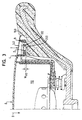
- Figure 3 shows the steering wheel of Figure 1 with the multifunction switch unit pressed.
In Figur 1 ist ein Fahrzeuglenkrad mit einem umschäumten Lenkradskelett
122 und einem Floating-hom-Gassackmodul 110 dargestellt. Das Lenkradskelett
122 bildet einen Grundkörper und ist mit einer topfförmigen Ausnehmung 100
ausgestattet, in welcher das Gassackmodul 110 in der in Figur 1 durch den Pfeil B
angedeuteten Richtung parallel zur Längsachse des Lenkrades verschiebbar gelagert
ist.In Figure 1 is a vehicle steering wheel with a foam-coated
Das Gassackmodul 110 weist ein wannenförmiges, nach oben offenes Modulgehäuse
114 auf, in dem ein Behälter 115 sitzt. Die zum Fahrzeuginsassen
weisende Oberfläche des Behälters 115 bildet eine Abdeckung 8, die aufreißbar
ist um einen im Innern des Behälters untergebrachten Gassack (in den Figuren
durch 116 angedeutet) austreten zu lassen. Außerdem ist im Inneren des Behälters
115 ein Gasgenerator 112 untergebracht, der mit seinem Generatorflansch 113 am
Modulgehäuse 114 befestigt ist, wobei zwischen dem Generatorflansch 113 und
dem Modulgehäuse 114 auch der Behälter 115 und der Gassack 116 befestigt
sind.The
An einem oberen Rand 120 des Modulgehäuses 114 ist im Bereich der
Speichen des Lenkrades, vorzugsweise links und rechts symmetrisch, jeweils ein
radialer Ausläufer 124 ausgebildet, an dem ein Träger 134 für einen ersten
Schalter 2 und einen zweiten Schalter 132 befestigt ist. Die Schalter 2, 132 sind
jeweils mit einem Druckstößel 150 bzw. 200 versehen, der zur Betätigung des
Schalters gedrückt werden kann.At an
Der Träger 134 weist vorzugsweise eine Leiterplatte auf, auf deren Oberseite
der erste Schalter 2 mit nach oben weisendem Druckstößel 150, und auf deren
Unterseite der zweite Schalter 132 mit nach unten weisendem Druckstößel 200,
angebracht ist. Der zweite Schalter 132 ragt durch eine Öffnung im Ausläufer
124, so daß der Druckstößel 200 an einer in der Umschäumung des Lenkradskeletts
122 ausgebildeten ebenen Anschlagfläche 160 anliegen kann, die sich
unter dem Ausläufer 124 im wesentlichen senkrecht zur Längsachse des Fahrzeuglenkrades
erstreckt. The
Am Ausläufer 124 ist ebenfalls ein erstes Betätigungselement in Form einer
Drucktaste 4 in Betätigungsrichtung B verschiebbar gelagert. Die Taste 4 besitzt
an ihrer zur Leiterplatte 134 gewandten Unterseite wenigstens eine Rippe 140, mit
der sie bei einer Verschiebung über den Druckstößel 150 den Schalter 2 betätigen
kann.There is also a first actuating element in the form of a on the
Der Schalter 2 dient zur Auslösung eines sogenannten Multifunktionsmerkmales
beispielsweise für die Bedienung von Bordcomputer, Radio, Navigationssystem
oder ähnlichem, so daß die Taste 4 und der Schalter 2 zusammen Teil
einer Multifunktionsschaltereinheit sind, von der im Schnitt der Figur 1 nur eine
Taste/Schalter-Kombination dargestellt ist. Die Multifunktionsschaltereinheit
kann jedoch mehrere solcher Taste/Schalter-Kombinationen aufweisen, die hintereinander
angeordnet sein können. Erfindungsgemäß besitzt wenigstens die Rippe
140 einer Taste 4 ein Stoppelement in Form eines nach unten hervorstehenden
Fortsatzes 9, der durch eine Öffnung im Ausläufer 124 greift.The
Der Schalter 132 dient als Hupkontaktschalter zur Auslösung der Hupe. Zu
seiner Betätigung muß eine Kraft auf die Abdeckung 8 ausgeübt werden, und
zwar in der Betätigungsrichtung B. Dadurch wird das verschiebbar gelagerte
Modulgehäuse 114 aus seiner Ruhestellung, wie sie in Figur 1 dargestellt ist, in
die Betätigungsstellung, die in Figur 2 dargestellt ist, verschoben, wobei selbstverständlich
auch der Träger 134 in der Betätigungsrichtung mitgenommen wird.
Dabei wird der Hupkontaktschalter 132 über den Druckstößel 200 von der
Anschlagfläche 160 betätigt. Um einen möglichst kurzen Betätigungsweg zu
erreichen, liegt der Druckstößel 200 vorzugsweise bereits in der Ruhestellung an
der Anschlagfläche 160 an, wie es in Figur 1 dargestellt ist.The
Nach dem Loslassen der Abdeckung 8 kehrt das Modulgehäuse 114 infolge
einer von Rückstellfedern 118 ausgeübten Rückstellkraft wieder in die Ruhelage
zurück.After the cover 8 is released, the
Wird, wie in Figur 3 dargestellt, die Taste 4 zur Auslösung eines Multifunktionsmerkmals
in der Betätigungsrichtung B nach unten gedrückt, so wird der
zugehörige Schalter 2 von der Rippe 140 durch den Druckstößel 150 betätigt.
Nachdem der Betätigungsweg W2 (siehe Fig. 2) des Schalters 2, der in der
dargestellten Ausführungsform beispielsweise 1,5 mm beträgt, zurückgelegt ist,
kommt der Fortsatz 9 an der Anschlagfläche 160 in Anschlag. Die Taste 4 kann
daher nicht weiter nach unten gedrückt werden. Damit ist aber zuverlässig
verhindert, daß bei weiterem Drücken der Taste 4 das Modulgehäuse 114
verschoben wird und damit der Hupkontaktschalter 132 durch "Überdrücken" der
Taste 4 versehentlich betätigt würde.If, as shown in FIG. 3, the button 4 is pressed down to trigger a multifunctional feature in the actuating direction B, the associated
Der Betätigungsweg W132 des Hupkontaktschalters 132 entspricht vorzugsweise
dem Betätigungsweg W2 des Schalters 2 der Multifunktionsschaltereinheit,
damit der Träger 134 bei Betätigung des Schalters 2 in keinem Fall in Bewegung
versetzt wird.The actuation path W 132 of the
Natürlich ist auch der Schalter 2 mit einer Rückstellfeder ausgestattet. Die
Kraft dieser Rückstellfeder ist jedoch wesentlich geringer als die der Rückstellfeder
118, so daß beim Drücken der Taste 4 zuerst die Rückstellfeder im
Schalter 2 zusammengedrückt wird.Of course,
Tritt der Fall ein, daß die Hupe durch Drücken der Abdeckung 8 ausgelöst
werden soll, während gleichzeitig die Taste 4 gedrückt ist, kann es dazu kommen,
daß durch die Abwärtsbewegung des Modulgehäuses 114 und die damit verbundene
Verschiebung des Trägers 134 die Betätigung des Schalters 2 aufgehoben
wird, da die Taste 4 durch den Anschlag des Fortsatzes 9 an der Anschlagfläche
160 daran gehindert wird, der Abwärtsbewegung des Trägers 134 zu folgen. Dies
kann aber durchaus wünschenswert sein, da vom Fahrer keine Betätigung der
Multifunktionsschaltereinheiten vorgenommen werden soll, wenn ganz offensichtlich
eine gefährliche Verkehrssituation vorliegt, die ihn zum Hupen veranlaßt
hat.Occurs when the horn is triggered by pressing the cover 8
If button 4 is pressed at the same time,
that by the downward movement of the
Die Schalter 2, 132 sind in der beschriebenen Ausführungsform als Mikroschalter
dargestellt, die beispielsweise als Öffner, Schließer oder Kombinationen
daraus ausgeführt sein können. Es sind jedoch auch andere Ausführungsform
denkbar, in denen die Schalter 2 beispielsweise durch Reed Kontakte oder
einfache Kontaktpaare repräsentiert sind, von denen jeweils ein Kontakt an der
Leiterplatte 134, der andere am Betätigungselement oder an einem durch dieses
verschiebbaren Zwischenelement angebracht sein kann.The
Das erste Betätigungselement 4 ist in der beschriebenen Ausführungsform am
Ausläufer 124 des Modulgehäuses 114 gelagert und damit relativ zum Träger 134
verschiebbar. Alternativ könnte das erste Betätigungselement auch direkt am
Träger oder aber am Grundkörper gelagert sein.The first actuating element 4 is in the embodiment described
Die Erfindung schafft also eine Kombination von Multifunktionsschaltereinheit und Floating-horn-Gassackmodul, die keine separaten Schalterträger zur Bewegungsentkopplung benötigt und dennoch die Möglichkeit eines ungewollten Hupens beim Betätigen von Multifunktionsschaltern ausschließt.The invention thus creates a combination of multi-function switch unit and floating horn gas bag module, which do not have separate switch carriers needed for decoupling motion and still the possibility of one excludes unwanted horns when using multifunction switches.
Claims (12)
Applications Claiming Priority (4)
| Application Number | Priority Date | Filing Date | Title |
|---|---|---|---|
| DE20216793 | 2002-10-30 | ||
| DE20216793U | 2002-10-30 | ||
| DE20309521U DE20309521U1 (en) | 2002-10-30 | 2003-06-20 | Steering wheel for motor vehicle, has two operation elements which operate two switches and stop element that prevents moving carrier using first operation element and operating second switch |
| DE20309521U | 2003-06-20 |
Publications (1)
| Publication Number | Publication Date |
|---|---|
| EP1415857A2 true EP1415857A2 (en) | 2004-05-06 |
Family
ID=32094885
Family Applications (1)
| Application Number | Title | Priority Date | Filing Date |
|---|---|---|---|
| EP20030022977 Withdrawn EP1415857A2 (en) | 2002-10-30 | 2003-10-10 | Vehicle steering wheel |
Country Status (2)
| Country | Link |
|---|---|
| US (1) | US6849816B2 (en) |
| EP (1) | EP1415857A2 (en) |
Cited By (1)
| Publication number | Priority date | Publication date | Assignee | Title |
|---|---|---|---|---|
| EP1623885A3 (en) * | 2004-08-03 | 2007-07-18 | TRW Automotive Safety Systems GmbH | Airbag module |
Families Citing this family (6)
| Publication number | Priority date | Publication date | Assignee | Title |
|---|---|---|---|---|
| DE20116306U1 (en) * | 2001-10-05 | 2002-02-14 | Trw Automotive Safety Sys Gmbh | vehicle steering wheel |
| DE20216754U1 (en) * | 2002-10-30 | 2003-03-20 | Trw Automotive Safety Sys Gmbh | Airbag module and vehicle steering wheel with an airbag module |
| DE20216755U1 (en) * | 2002-10-30 | 2003-03-20 | Trw Automotive Safety Sys Gmbh | steering wheel |
| JP4907159B2 (en) * | 2005-11-22 | 2012-03-28 | タカタ株式会社 | Airbag device and steering wheel |
| WO2008060193A1 (en) * | 2006-11-13 | 2008-05-22 | Autoliv Development Ab | An air-bag cover arrangement |
| DE102009007777A1 (en) * | 2009-02-04 | 2010-08-05 | Takata-Petri Ag | Steering wheel assembly for a motor vehicle |
Family Cites Families (12)
| Publication number | Priority date | Publication date | Assignee | Title |
|---|---|---|---|---|
| US4518836A (en) * | 1984-04-17 | 1985-05-21 | United Technologies Automotive, Inc. | Control pod and switch assembly |
| US4590340A (en) * | 1985-01-29 | 1986-05-20 | Nihon Plast Co., Ltd. | Steering wheel assembly for vehicles |
| US4872364A (en) * | 1987-10-27 | 1989-10-10 | Toyoda Gosei Co., Ltd. | Steering wheel |
| US5303952A (en) * | 1992-12-23 | 1994-04-19 | United Technologies Automotive, Inc. | Electric signalling in a supplemental vehicle restraint system |
| US5627352A (en) * | 1994-09-28 | 1997-05-06 | Toyoda Gosei Co., Ltd. | Steering wheel |
| IT1284667B1 (en) * | 1996-07-16 | 1998-05-21 | Bruzolo Manifatt Gestind Mb | STEERING WHEEL FOR MOTOR VEHICLES WITH SWITCH FOR THE CONTROL OF A HORN. |
| JPH11329157A (en) * | 1998-05-21 | 1999-11-30 | Alps Electric Co Ltd | Switch device |
| JP3719861B2 (en) * | 1998-11-12 | 2005-11-24 | アルプス電気株式会社 | Steering device |
| DE29918483U1 (en) * | 1999-10-21 | 2000-03-02 | Trw Automotive Safety Sys Gmbh | Vehicle steering wheel |
| DE19956872B4 (en) | 1999-11-26 | 2005-09-01 | Audi Ag | Steering wheel for a motor vehicle |
| JP3789284B2 (en) * | 2000-04-28 | 2006-06-21 | アルプス電気株式会社 | Switch unit for vehicle steering wheel |
| DE20010543U1 (en) | 2000-06-14 | 2001-02-22 | Trw Automotive Safety Sys Gmbh | Multifunctional steering wheel |
-
2003
- 2003-10-10 EP EP20030022977 patent/EP1415857A2/en not_active Withdrawn
- 2003-10-23 US US10/692,218 patent/US6849816B2/en not_active Expired - Fee Related
Cited By (1)
| Publication number | Priority date | Publication date | Assignee | Title |
|---|---|---|---|---|
| EP1623885A3 (en) * | 2004-08-03 | 2007-07-18 | TRW Automotive Safety Systems GmbH | Airbag module |
Also Published As
| Publication number | Publication date |
|---|---|
| US20040089527A1 (en) | 2004-05-13 |
| US6849816B2 (en) | 2005-02-01 |
Similar Documents
| Publication | Publication Date | Title |
|---|---|---|
| EP1102289B1 (en) | Rotary switch | |
| DE602006000125T2 (en) | Belt lock switch, belt buckle with a buckle switch, and seat belt with buckle | |
| EP1197402B1 (en) | Vehicle steering wheel | |
| DE4242157B4 (en) | Module cover for an airbag system | |
| EP2426012A1 (en) | Steering wheel for a motor vehicle | |
| EP1612102B1 (en) | Steering wheel with operating element | |
| DE19625501C2 (en) | Control element arrangement for controlling the longitudinal and transverse movement of a motor vehicle | |
| EP2945832A1 (en) | Steering wheel with optical finger navigation module | |
| EP1415857A2 (en) | Vehicle steering wheel | |
| DE69924909T2 (en) | steering device | |
| WO2000001552A1 (en) | Device for detecting pressure exerted upon the seat of a motor vehicle | |
| DE19622493C2 (en) | Switching device for motor vehicles | |
| DE4117303C2 (en) | Horn control insert for a steering wheel | |
| EP1393972B1 (en) | Switching device for vehicle horn | |
| EP1164054A1 (en) | Multifunction steering wheel | |
| DE2304801C3 (en) | Steering column switches for automobiles | |
| EP1702796B1 (en) | Combined push button and rotary switch for a vehicle | |
| DE60008816T2 (en) | steering wheel switches | |
| DE102013003574B4 (en) | Pressure and rotary control element for a motor vehicle | |
| EP3934930B1 (en) | Circuit arrangement | |
| DE102006016160A1 (en) | Steering arrangement, particularly steering wheel for motor vehicle, has carrier for attachment of steering column, where control element is pre-stressed with electrical force in direction of switching element | |
| EP1772314A1 (en) | Actuating device for an electrically-powered signalling device | |
| EP1281586B1 (en) | Steering wheel with movable airbag module | |
| DE2224889C2 (en) | Switch combination for steering columns of motor vehicles | |
| DE102004051434A1 (en) | Airbag module housing for motor vehicle, has U-shaped or horseshoe shaped contact plate arranged on side of housing, and fixing unit that is arranged as snap-fit in area of steering wheel hub |
Legal Events
| Date | Code | Title | Description |
|---|---|---|---|
| PUAI | Public reference made under article 153(3) epc to a published international application that has entered the european phase |
Free format text: ORIGINAL CODE: 0009012 |
|
| AK | Designated contracting states |
Kind code of ref document: A2 Designated state(s): AT BE BG CH CY CZ DE DK EE ES FI FR GB GR HU IE IT LI LU MC NL PT RO SE SI SK TR |
|
| AX | Request for extension of the european patent |
Extension state: AL LT LV MK |
|
| STAA | Information on the status of an ep patent application or granted ep patent |
Free format text: STATUS: THE APPLICATION IS DEEMED TO BE WITHDRAWN |
|
| 18D | Application deemed to be withdrawn |
Effective date: 20080501 |