EP1415583B1 - Floor suction tool for electric vacuum cleaners - Google Patents
Floor suction tool for electric vacuum cleaners Download PDFInfo
- Publication number
- EP1415583B1 EP1415583B1 EP03024582A EP03024582A EP1415583B1 EP 1415583 B1 EP1415583 B1 EP 1415583B1 EP 03024582 A EP03024582 A EP 03024582A EP 03024582 A EP03024582 A EP 03024582A EP 1415583 B1 EP1415583 B1 EP 1415583B1
- Authority
- EP
- European Patent Office
- Prior art keywords
- cover
- main body
- suction tool
- body casing
- floor suction
- Prior art date
- Legal status (The legal status is an assumption and is not a legal conclusion. Google has not performed a legal analysis and makes no representation as to the accuracy of the status listed.)
- Expired - Lifetime
Links
- 239000004744 fabric Substances 0.000 claims description 9
- 239000002657 fibrous material Substances 0.000 claims description 6
- 239000000463 material Substances 0.000 claims description 6
- 238000004140 cleaning Methods 0.000 description 14
- 239000000428 dust Substances 0.000 description 13
- 238000010276 construction Methods 0.000 description 4
- 238000013459 approach Methods 0.000 description 2
- 230000005540 biological transmission Effects 0.000 description 2
- 230000000694 effects Effects 0.000 description 2
- 230000035939 shock Effects 0.000 description 2
- 239000006096 absorbing agent Substances 0.000 description 1
- 230000015572 biosynthetic process Effects 0.000 description 1
- 238000009408 flooring Methods 0.000 description 1
- 238000012986 modification Methods 0.000 description 1
- 230000004048 modification Effects 0.000 description 1
- 230000002093 peripheral effect Effects 0.000 description 1
- 238000007790 scraping Methods 0.000 description 1
- 238000007789 sealing Methods 0.000 description 1
- 239000010902 straw Substances 0.000 description 1
Images


Classifications
-
- A—HUMAN NECESSITIES
- A47—FURNITURE; DOMESTIC ARTICLES OR APPLIANCES; COFFEE MILLS; SPICE MILLS; SUCTION CLEANERS IN GENERAL
- A47L—DOMESTIC WASHING OR CLEANING; SUCTION CLEANERS IN GENERAL
- A47L9/00—Details or accessories of suction cleaners, e.g. mechanical means for controlling the suction or for effecting pulsating action; Storing devices specially adapted to suction cleaners or parts thereof; Carrying-vehicles specially adapted for suction cleaners
- A47L9/02—Nozzles
- A47L9/04—Nozzles with driven brushes or agitators
Definitions
- the present invention relates to a floor suction tool for electric vacuum cleaners according to the preamble of claim 1.
- a floor suction tool of the above type is known from US 4,499,628 .
- suction tools capable of cleaning at walls and the like, suction tools constructed to suck dust at walls and the like by moving upward or turning backward flaps or sealing members mounted on lower parts of front faces of bodies of the suction tools when the bodies of the suction tools are pushed against walls and the like. See Japanese Patent Laid-Open Nos. 1996-317886 and 1996-206043 , for example.
- the rotary plate has the shape of an arch in a sectional view in a direction perpendicular to the rotation axis of a rotary brush.
- the arch shape has a greater diameter than the rotation trajectory of the tips of bristles of the rotary brush.
- the rotary plate opens and closes a front face of a body of the suction tool.
- the rotary plate is mounted on the body of the suction tool in a freely rotatable manner about a rotation axis that is co-axial to the rotation axis of the rotary brush.
- the rotary plate is manually operated to open or close the front face of the body of the suction tool. See Japanese Published Unexamined Utility Model Application No. 1991-949 , for example.
- the present invention has been made to solve the above-described problems, and an object of the invention is to provide a floor suction tool for electric vacuum cleaners capable of efficiently sucking dust gathering at walls, or in corners defined between upright walls, furniture or obstacles and floors (hereinafter at walls or at a wall for simplicity), avoiding the marring of walls and furniture and providing a smooth move.
- the invention provides a floor suction tool according to claim 1 in order to solve the above-identified object.
- the abutting member may be formed to be a rotatable roller.
- At least a surface of the abutting member is formed of a soft, smooth material.
- a fibrous material is used as the soft, smooth material.
- a raising cloth may be mentioned.
- the cover may open the front face of the main body casing by rotating along an inside face of an upper case of the main body casing and being received in the upper case.
- the floor suction tool of the invention may be constructed to include, in the main body casing, a rotary brush having bristles fixed thereto radially.
- the rotary brush may be so formed that the tips of the bristles projects forward in relation to a trajectory of the cover when the cover opens.
- the cover may be constructed to receive a spring force in a closing direction by a spring member attached to the rotation axis.
- the cover may be so constructed that the own weight of the cover acts as a force in the closing direction.
- Figs. 1 to 10 illustrate the construction and working of a floor suction tool 1 in accordance with an example of the invention.
- the floor suction tool 1 shown in Figs. 1 to 10 includes a laterally elongated main body casing 2 which is composed of an upper case 2a and a lower case 2b and has a suction opening 6, a rotary brush 3 supported in a freely rotatable manner by bearings on both ends within the main body casing 2 in the width direction as seen from the front of the main body casing 2, a bend 4 mounted on a rear face of the main body casing 2, the bend 4 being communicated to the suction opening 6 and being pivotable in all directions, and a cover 5 defining a front wall of the main body casing 2 and functioning to open and close the front wall of the main body casing 2.
- the suction opening 6 opens widely from a bottom face to a front face of the main body casing 2 and has a bottom portion 6a and a front portion 6b.
- the suction opening 6 has the bottom portion 6a alone.
- the bend 4 is connected to a vacuum cleaner by an extension tube or a hose.
- the cover 5 is generally in a bent shape in cross section as shown in Fig. 4 .
- An upper portion thereof is arch-shaped.
- a roller 7 is mounted on the cover 5 with both ends of the roller 7 supported in a freely rotatable manner by bearings 7a.
- the roller 7 functions as an abutting member or a bumper when the front of the floor suction tool 1 abuts to a wall.
- the outer side of the bearing 7a is tapered in a forward direction as shown in Fig. 7 so that the floor suction tool 1 can be smoothly moved if the outer side of the bearing 7a abuts to an obstacle during cleaning.
- a peripheral surface of a core 7c having a rotation axis 7b is covered with a raising cloth 7d which is a fibrous material as a soft, smooth abutting member, as shown in Fig. 5 .
- Arms 8 are formed integrally on both ends of the thus constructed cover 5 as shown in Figs. 6 and 7 .
- the arms 8 on the ends are supported in a freely rotatable manner about a rotation axis 9 which is formed, inside of both ends of the main body casing 2, horizontally in parallel with the front wall of the main body casing 2.
- the positional relationship between the rotation axis 9 and the roller 7 is such that the roller 7 is positioned above the rotation axis 9 which is the rotation center of the cover 5.
- the cover 5 is constructed to rotate in such a direction that the cover 5 goes inside the upper case 2a of the main body casing 2 when the roller 7 abuts to the wall W and the cover 5 rotates upward.
- a torsional spring 9a is mounted as a bias means for biasing the cover 5 so that the cover 5 rotates in a downward direction.
- the rotary brush 3 has four helical grooves 11 in the longitudinal direction at intervals of 90 degrees on an outer periphery of a core 10.
- a pair of sets of bristles 12a and a pair of rubber blades 12b are alternately mounted in the grooves 11.
- the bristles 12a are longer than the rubber blades 12b.
- the positional relationship between the rotary brush 3 and the cover 5 is so set that the rotation trajectory of the tips of the bristles 12a comes ahead of the roller 7 when the cover 5 is open as shown in Fig. 9 .
- the rotary brush 3 is constructed to be rotationally driven by transmission of a drive force from an electric motor contained in the main body casing 2 via a transmission belt or the like, though that is not shown.
- roller 7 mounted on the cover 5 also functions as a bumper at the front of the main body casing 2, but side bumpers 14 are also mounted on both sides of the main body casing 2.
- a floor brush 15 is mounted on a rear side of the bottom portion 6a of the suction opening 6 along the width direction of the suction opening 6 as shown in Figs. 4 , 8 , 9 and 10 .
- the thus constructed floor suction tool 1 of the example opens only the bottom portion 6a of the suction opening 6 in cleaning ordinary floors (e.g., floors carpeted with flooring, straw tatami mats, carpets, etc.) since, as shown in Fig. 4 , the cover 5 is rotated down in a lower position by the biasing force of the torsional spring 9a mounted on the rotation axis 9 and closes the front portion 6b of the suction opening 6. Therefore, there does not occur a loss in the volume of suction air, and a desired volume of suction air can be obtained at the bottom portion 6a of the suction opening 6. In addition to that, the rotary brush 3 has a scraping effect. Thus the floor suction tool 1 provides an efficient floor cleaning.
- floors carpeted with flooring, straw tatami mats, carpets, etc. since, as shown in Fig. 4 , the cover 5 is rotated down in a lower position by the biasing force of the torsional spring 9a mounted on the rotation axis 9 and closes the
- the suction tool 1 is pushed against the wall W as shown in Fig. 8 .
- the roller 7 mounted on the cover 5 first abuts to the wall W and rotates as shown by an arrow to lift the cover 5.
- the cover 5 rotates about the rotation axis 9 in the direction in which the cover 5 is accommodated inside the upper case 2a of the main body casing 2.
- the front portion 6a of the suction opening 6 is fully opened as shown in Fig. 9 .
- the suction opening 6 is very close to the wall.
- the floor suction tool 1 has a sufficient cleaning effect on dust at the wall.
- the dust at the wall can be sucked from both the bottom portion 6a and the front portion 6b of the suction opening 6.
- the rotary brush 3 approaches or abuts to the wall W to scrape the dust at the wall. Consequently, the dust at the wall can be efficiently sucked.
- the cover 5 itself does not abut to walls or furniture but the roller 7 whose outer periphery is covered with the raising cloth abuts to the walls, the walls W and furniture can be positively prevented from being marred, and the cover 5 can be rotated very smoothly.
- the covering of the outer periphery of the roller 7 with the raising cloth also provides a smooth horizontal movement of the suction tool 1 in cleaning in the lateral direction with the roller 7 abutting to the wall W.
- the roller 7 Because the roller 7 is mounted on the front of the main body casing 2, the roller 7 also functions as a bumper which absorbs shock when the front of the main body casing 2 hits an obstacle.
- the cover 5 rotates along the inside of the main body casing 2 to be accommodated therein, it is possible to reduce the height of the suction tool 1 as compared with a suction tool whose cover 5 rotates along the outside of the main body casing 2. Therefore, when the suction tool 1 is used for cleaning a place of low height, for example, under a bed, there does not occur a problem that the cover 5 fails to open because of hitting an obstacle.
- the suction tool 1 also has a strengthened structure against external force.
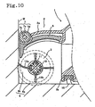
- the front-to-back positional relationship between the roller 7 and the bristles 12a and rubber blades 12b of the rotary brush 3 is such that the rotation trajectory of the tips of the bristles 12a is ahead of the roller 7 and contacts the wall W in a state in which the roller 7 abuts to the wall W, as shown in Fig. 10 . Therefore, dust on and at the wall W can be efficiently sucked. Since the rubber blades 12b produce an unusual noise on hitting the wall, the rubber blades 12b are positioned so as not to contact the wall W in the above-mentioned state.
- the cover 5 When an ordinary floor is cleaned after the above-described cleaning at the wall, the cover 5 is rotated downward by the biasing force of the torsional spring 9a to close the front portion 6b of the suction opening 6 only by moving the suction tool 1 off the wall W.
- the ordinary floor can be cleaned in an ordinary manner.
- the cover 5 can be rotated downward only by its own weight to close the front portion 6b of the suction opening 6.
- the torsional spring 9a for rotating the cover 5 downward as in this example the front portion 6b can be reliably closed even if dust adheres to the rotation axis 9 of the cover 5.
- the single roller 7 is provided along the width direction of the cover 5.
- the invention is not limited thereto.
- short rollers 71 and 72 may be mounted on both sides of the cover 5 in the width direction and be supported rotatably on bearings 7a mounted on the front of the cover 5.
- the invention is applied to the floor suction tool whose rotary brush 3 is a brush rotationally driven by a motor (a power brush).
- the invention is not limited thereto.
- the invention is also applicable to a floor suction tool with a turbine brush or a brush which is rotated by directly receiving sucked air using the rubber blade 12b of the rotary brush 3 or the like.
- a notch 5a in the center or on both sides of the bottom of the cover 5 for sucking air in the direction shown by an arrow in Fig. 13 , which air is then received by the rubber blade 12b or the like to rotatably drive the rotary brush 3.
- the rotary brush 3 is capable of rotating since air can passes through the outer periphery of the roller 7 made of the raising cloth 7d and through air paths ensured on both the sides.
- rollers 71 and 72 are mounted on both the sides of the cover 5, air can be sufficiently taken between the rollers.
- the rotating force of the rotary brush 3 can be increased.
- the roller 7 is provided in the cover 5.
- the cover 5 itself may have a projection projecting forward as an abutting member which abuts to a wall W and the outer surface of the projection may be covered with a raising cloth 7d as in the above-described example.
- the cover 5 rotates in the direction in which the cover 5 is accommodated in the main body casing 2 when the floor suction tool 1 abuts to the wall W.
- the invention is not limited thereto.
- the cover 5 rotates along the outside of the upper case 2a of the main body casing 2, the intended object of the invention can be achieved by covering a part of the cover 5 abutting to the wall W with a raising cloth 7d as in the above-described example.
- the floor suction tool 1 for electric vacuum cleaners includes the suction opening 6 formed on the bottom face of the main body casing 2; the cover 5 defining the front wall of the main body casing 2; and the abutting member projecting from the front face of the cover 5 and functioning as a bumper between the front face of the main body casing 2 and a wall.
- the cover 5 is rotatably supported on the rotation axis 7b formed horizontally in the width direction of the front wall of the main body casing 2. The cover 5 rotates upward to open the front face of the main body casing 2 when the front-to-back force acts on the abutting member.
- the cover 5 rotates downward to close the front face of the main body casing 2 when the front-to-back force ceases. Therefore, in cleaning at walls, the cover 5 is pushed up by pressing the suction tool 1 against the wall, so that the suction opening 6 approaches the wall. Thus dust gathering at the walls can be efficiently sucked.
- the formation of at least of the front surface of the abutting member of a soft, smooth material allows the abutting member to act as a shock absorber. That prevents walls and furniture from being marred by the suction tool 1 and also the cover 5 can be rotated smoothly. Further, the smooth lateral movement of the suction tool 1 can be obtained when cleaning is carried out in the lateral direction with the abutting member abutting to the wall.
- a fibrous material more particularly, a raising cloth as the soft, smooth material smoothens the lateral movement more when cleaning is carried out in the lateral direction with the abutting member abutting to the wall.
- the suction tool 1 With the construction wherein the cover 5 rotates in the direction in which the cover 5 is accommodated in the main body casing 2 of the suction tool 1, the suction tool 1 can have a reduced height. Thus, even in cleaning a place of low height, for example, under a bed, there does not occur a problem that the cover 5 fails to open because of hitting an obstacle.
- the suction tool 1 has a reinforced structure against external force.
- bias means 9a for biasing the cover 5 downward can ensure the closing of the front portion 6b of the suction opening 6 even if more or less dust adheres to the rotation axis of the cover 5.
- the cover 5 may be so formed that its own weight acts as a force in the direction of closing the cover 5. Thereby it is possible to omit or simplify the bias means 9a.
Landscapes
- Engineering & Computer Science (AREA)
- Mechanical Engineering (AREA)
- Nozzles For Electric Vacuum Cleaners (AREA)
- Massaging Devices (AREA)
- Filters For Electric Vacuum Cleaners (AREA)
Abstract
Description
- The present invention relates to a floor suction tool for electric vacuum cleaners according to the preamble of claim 1.
- A floor suction tool of the above type is known from
US 4,499,628 . - Common floor suction tools have suction openings only on bottom faces of main body casings of the suction tools. For this reason, it is difficult to clean places with upright obstacles such as walls, legs of furniture and the like.
- To cope with this problem, there have been proposed, as suction tools capable of cleaning at walls and the like, suction tools constructed to suck dust at walls and the like by moving upward or turning backward flaps or sealing members mounted on lower parts of front faces of bodies of the suction tools when the bodies of the suction tools are pushed against walls and the like. See
Japanese Patent Laid-Open Nos. 1996-317886 1996-206043 - Also suction tools having rotary plates have been proposed. The rotary plate has the shape of an arch in a sectional view in a direction perpendicular to the rotation axis of a rotary brush. The arch shape has a greater diameter than the rotation trajectory of the tips of bristles of the rotary brush. The rotary plate opens and closes a front face of a body of the suction tool. The rotary plate is mounted on the body of the suction tool in a freely rotatable manner about a rotation axis that is co-axial to the rotation axis of the rotary brush. The rotary plate is manually operated to open or close the front face of the body of the suction tool. See
Japanese Published Unexamined Utility Model Application No. 1991-949 - However, even if the lower part of the front of the body of the suction tool is opened for sucking dust as disclosed in
Japanese Patent Laid-Open Nos. 1996-317886 1996-206043 - Besides, the suction tool disclosed in
Japanese Published Unexamined Utility Model Application No. 1991-949 - The present invention has been made to solve the above-described problems, and an object of the invention is to provide a floor suction tool for electric vacuum cleaners capable of efficiently sucking dust gathering at walls, or in corners defined between upright walls, furniture or obstacles and floors (hereinafter at walls or at a wall for simplicity), avoiding the marring of walls and furniture and providing a smooth move.
- The invention provides a floor suction tool according to claim 1 in order to solve the above-identified object.
- The abutting member may be formed to be a rotatable roller.
- Preferably, at least a surface of the abutting member is formed of a soft, smooth material.
- Preferably a fibrous material is used as the soft, smooth material. As the fibrous material, a raising cloth may be mentioned.
- The cover may open the front face of the main body casing by rotating along an inside face of an upper case of the main body casing and being received in the upper case.
- Preferably, the floor suction tool of the invention may be constructed to include, in the main body casing, a rotary brush having bristles fixed thereto radially. The rotary brush may be so formed that the tips of the bristles projects forward in relation to a trajectory of the cover when the cover opens.
- The cover may be constructed to receive a spring force in a closing direction by a spring member attached to the rotation axis.
- The cover may be so constructed that the own weight of the cover acts as a force in the closing direction.
- These and other objects of the present invention will become more readily apparent from the detailed description given hereinafter. However, it should be understood that the detailed description and specific examples, while indicating preferred embodiments of the invention, are given by way of illustration only, since various changes and modifications within the scope of the invention will become apparent to those skilled in the art from this detailed description.
-
-
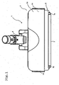
Fig. 1 is a top view of a floor suction tool in accordance with an example of the present invention; -
Fig. 2 is a front view of the floor suction tool; -
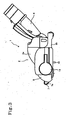
Fig. 3 is a side view of the floor suction tool; -
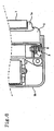
Fig. 4 is a vertical sectional view of a central part of the floor suction tool; -
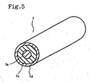
Fig. 5 is a perspective view of a roller of the floor suction tool which is vertically sectioned in part; -
Fig. 6 is a top view of the floor suction tool with an upper case thereof removed; -
Fig. 7 is a sectional side view of the floor suction tool with the upper case thereof removed; -
Fig. 8 is a vertical sectional view in part of the floor suction tool when a cover thereof is opening; -
Fig. 9 is a vertical sectional view of the floor suction tool with the cover thereof opened; -
Fig. 10 is a vertical sectional view in part of the floor suction tool, illustrating a working of the floor suction tool when the cover is open. -
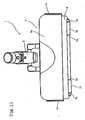
Fig. 11 is a top view of a floor suction tool in accordance with another example of the present invention; -
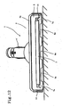
Fig. 12 is a front view of a floor suction tool in accordance with still another example of the present invention; -
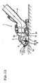
Fig. 13 is a vertical sectional view of a central part of the floor suction tool ofFig. 12 ; -
Fig. 14 is a vertical sectional view of a central part of a floor suction tool in accordance with still another example of the present invention; -
Fig. 15 is a vertical sectional view of the floor suction tool ofFig. 14 with a cover thereof opened; -
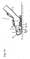
Fig. 16 is a vertical sectional view of a central part of a floor suction tool in accordance with still another example of the present invention; -
Fig. 17 is a vertical sectional view of the floor suction tool ofFig. 16 with a cover thereof opened. - The present invention is now described in detail with reference to the drawings.
-
Figs. 1 to 10 illustrate the construction and working of a floor suction tool 1 in accordance with an example of the invention. - As shown in
Fig. 4 , the floor suction tool 1 shown inFigs. 1 to 10 includes a laterally elongatedmain body casing 2 which is composed of anupper case 2a and alower case 2b and has a suction opening 6, arotary brush 3 supported in a freely rotatable manner by bearings on both ends within themain body casing 2 in the width direction as seen from the front of themain body casing 2, a bend 4 mounted on a rear face of themain body casing 2, the bend 4 being communicated to the suction opening 6 and being pivotable in all directions, and acover 5 defining a front wall of themain body casing 2 and functioning to open and close the front wall of themain body casing 2. When thecover 5 opens, the suction opening 6 opens widely from a bottom face to a front face of themain body casing 2 and has abottom portion 6a and afront portion 6b. When thecover 5 closes, the suction opening 6 has thebottom portion 6a alone. The bend 4 is connected to a vacuum cleaner by an extension tube or a hose. - The
cover 5 is generally in a bent shape in cross section as shown inFig. 4 . An upper portion thereof is arch-shaped. Aroller 7 is mounted on thecover 5 with both ends of theroller 7 supported in a freely rotatable manner bybearings 7a. Theroller 7 functions as an abutting member or a bumper when the front of the floor suction tool 1 abuts to a wall. The outer side of thebearing 7a is tapered in a forward direction as shown inFig. 7 so that the floor suction tool 1 can be smoothly moved if the outer side of the bearing 7a abuts to an obstacle during cleaning. - In the
roller 7, a peripheral surface of acore 7c having arotation axis 7b is covered with a raisingcloth 7d which is a fibrous material as a soft, smooth abutting member, as shown inFig. 5 . -
Arms 8 are formed integrally on both ends of the thus constructedcover 5 as shown inFigs. 6 and7 . Thearms 8 on the ends are supported in a freely rotatable manner about a rotation axis 9 which is formed, inside of both ends of themain body casing 2, horizontally in parallel with the front wall of themain body casing 2. The positional relationship between the rotation axis 9 and theroller 7 is such that theroller 7 is positioned above the rotation axis 9 which is the rotation center of thecover 5. With this construction, when theroller 7 is pressed against a wall W as shown inFig. 7 , that is, theroller 7 receives the front-to-back force, theroller 7 rotates anticlockwise as shown by an arrow inFig. 8 so that the cover rotates upward. - Also, as shown in
Fig. 8 , thecover 5 is constructed to rotate in such a direction that thecover 5 goes inside theupper case 2a of themain body casing 2 when theroller 7 abuts to the wall W and thecover 5 rotates upward. - Referring to
Figs. 6 and7 , atorsional spring 9a is mounted as a bias means for biasing thecover 5 so that thecover 5 rotates in a downward direction. - Further, as shown in
Figs. 9 and10 , therotary brush 3 has four helical grooves 11 in the longitudinal direction at intervals of 90 degrees on an outer periphery of acore 10. A pair of sets ofbristles 12a and a pair ofrubber blades 12b are alternately mounted in the grooves 11. Thebristles 12a are longer than therubber blades 12b. The positional relationship between therotary brush 3 and thecover 5 is so set that the rotation trajectory of the tips of thebristles 12a comes ahead of theroller 7 when thecover 5 is open as shown inFig. 9 . - The
rotary brush 3 is constructed to be rotationally driven by transmission of a drive force from an electric motor contained in themain body casing 2 via a transmission belt or the like, though that is not shown. - In this example, the
roller 7 mounted on thecover 5 also functions as a bumper at the front of themain body casing 2, butside bumpers 14 are also mounted on both sides of themain body casing 2. Afloor brush 15 is mounted on a rear side of thebottom portion 6a of thesuction opening 6 along the width direction of thesuction opening 6 as shown inFigs. 4 ,8 ,9 and10 . - The thus constructed floor suction tool 1 of the example opens only the
bottom portion 6a of thesuction opening 6 in cleaning ordinary floors (e.g., floors carpeted with flooring, straw tatami mats, carpets, etc.) since, as shown inFig. 4 , thecover 5 is rotated down in a lower position by the biasing force of thetorsional spring 9a mounted on the rotation axis 9 and closes thefront portion 6b of thesuction opening 6. Therefore, there does not occur a loss in the volume of suction air, and a desired volume of suction air can be obtained at thebottom portion 6a of thesuction opening 6. In addition to that, therotary brush 3 has a scraping effect. Thus the floor suction tool 1 provides an efficient floor cleaning. - On the other hand, in cleaning at a wall, the suction tool 1 is pushed against the wall W as shown in
Fig. 8 . Thereby, theroller 7 mounted on thecover 5 first abuts to the wall W and rotates as shown by an arrow to lift thecover 5. Then thecover 5 rotates about the rotation axis 9 in the direction in which thecover 5 is accommodated inside theupper case 2a of themain body casing 2. Thus thefront portion 6a of thesuction opening 6 is fully opened as shown inFig. 9 . - In the state shown in
Fig. 9 , thesuction opening 6 is very close to the wall. Thus the floor suction tool 1 has a sufficient cleaning effect on dust at the wall. Furthermore, the dust at the wall can be sucked from both thebottom portion 6a and thefront portion 6b of thesuction opening 6. Moreover, therotary brush 3 approaches or abuts to the wall W to scrape the dust at the wall. Consequently, the dust at the wall can be efficiently sucked. - In this example, because the
cover 5 itself does not abut to walls or furniture but theroller 7 whose outer periphery is covered with the raising cloth abuts to the walls, the walls W and furniture can be positively prevented from being marred, and thecover 5 can be rotated very smoothly. The covering of the outer periphery of theroller 7 with the raising cloth also provides a smooth horizontal movement of the suction tool 1 in cleaning in the lateral direction with theroller 7 abutting to the wall W. - Because the
roller 7 is mounted on the front of themain body casing 2, theroller 7 also functions as a bumper which absorbs shock when the front of the main body casing 2 hits an obstacle. - Further, because the
cover 5 rotates along the inside of themain body casing 2 to be accommodated therein, it is possible to reduce the height of the suction tool 1 as compared with a suction tool whosecover 5 rotates along the outside of themain body casing 2. Therefore, when the suction tool 1 is used for cleaning a place of low height, for example, under a bed, there does not occur a problem that thecover 5 fails to open because of hitting an obstacle. The suction tool 1 also has a strengthened structure against external force. - When the
cover 5 is open, the front-to-back positional relationship between theroller 7 and thebristles 12a andrubber blades 12b of therotary brush 3 is such that the rotation trajectory of the tips of thebristles 12a is ahead of theroller 7 and contacts the wall W in a state in which theroller 7 abuts to the wall W, as shown inFig. 10 . Therefore, dust on and at the wall W can be efficiently sucked. Since therubber blades 12b produce an unusual noise on hitting the wall, therubber blades 12b are positioned so as not to contact the wall W in the above-mentioned state. - When an ordinary floor is cleaned after the above-described cleaning at the wall, the
cover 5 is rotated downward by the biasing force of thetorsional spring 9a to close thefront portion 6b of thesuction opening 6 only by moving the suction tool 1 off the wall W. Thus the ordinary floor can be cleaned in an ordinary manner. - The
cover 5 can be rotated downward only by its own weight to close thefront portion 6b of thesuction opening 6. However, by the provision of thetorsional spring 9a for rotating thecover 5 downward as in this example, thefront portion 6b can be reliably closed even if dust adheres to the rotation axis 9 of thecover 5. - In the above-described example, the
single roller 7 is provided along the width direction of thecover 5. However, the invention is not limited thereto. For example, as shown inFig. 11 ,short rollers cover 5 in the width direction and be supported rotatably onbearings 7a mounted on the front of thecover 5. - In the above-described example, the invention is applied to the floor suction tool whose
rotary brush 3 is a brush rotationally driven by a motor (a power brush). However, the invention is not limited thereto. The invention is also applicable to a floor suction tool with a turbine brush or a brush which is rotated by directly receiving sucked air using therubber blade 12b of therotary brush 3 or the like. In this case, for example, as shown inFigs. 12 and13 , it is possible to provide anotch 5a in the center or on both sides of the bottom of thecover 5 for sucking air in the direction shown by an arrow inFig. 13 , which air is then received by therubber blade 12b or the like to rotatably drive therotary brush 3. In this suction tool, even while thecover 5 is opened by the abutment of theroller 7 to a wall, therotary brush 3 is capable of rotating since air can passes through the outer periphery of theroller 7 made of the raisingcloth 7d and through air paths ensured on both the sides. However, ifrollers cover 5, air can be sufficiently taken between the rollers. Thus, the rotating force of therotary brush 3 can be increased. - In the above-described example, the
roller 7 is provided in thecover 5. However, the invention is not limited thereto. For example, as shown inFigs. 14 and15 , thecover 5 itself may have a projection projecting forward as an abutting member which abuts to a wall W and the outer surface of the projection may be covered with a raisingcloth 7d as in the above-described example. - In the above-described example, the
cover 5 rotates in the direction in which thecover 5 is accommodated in themain body casing 2 when the floor suction tool 1 abuts to the wall W. However, the invention is not limited thereto. For example, as shown inFigs. 16 and17 , if thecover 5 rotates along the outside of theupper case 2a of themain body casing 2, the intended object of the invention can be achieved by covering a part of thecover 5 abutting to the wall W with a raisingcloth 7d as in the above-described example. - As described above, according to the present invention, the floor suction tool 1 for electric vacuum cleaners includes the
suction opening 6 formed on the bottom face of themain body casing 2; thecover 5 defining the front wall of themain body casing 2; and the abutting member projecting from the front face of thecover 5 and functioning as a bumper between the front face of themain body casing 2 and a wall. Thecover 5 is rotatably supported on therotation axis 7b formed horizontally in the width direction of the front wall of themain body casing 2. Thecover 5 rotates upward to open the front face of themain body casing 2 when the front-to-back force acts on the abutting member. Thecover 5 rotates downward to close the front face of themain body casing 2 when the front-to-back force ceases. Therefore, in cleaning at walls, thecover 5 is pushed up by pressing the suction tool 1 against the wall, so that thesuction opening 6 approaches the wall. Thus dust gathering at the walls can be efficiently sucked. - The provision of the
rotatable roller 7 as the abutting member allows thecover 5 to be rotated more smoothly. - The formation of at least of the front surface of the abutting member of a soft, smooth material allows the abutting member to act as a shock absorber. That prevents walls and furniture from being marred by the suction tool 1 and also the
cover 5 can be rotated smoothly. Further, the smooth lateral movement of the suction tool 1 can be obtained when cleaning is carried out in the lateral direction with the abutting member abutting to the wall. - The use of a fibrous material, more particularly, a raising cloth as the soft, smooth material smoothens the lateral movement more when cleaning is carried out in the lateral direction with the abutting member abutting to the wall.
- With the construction wherein the
cover 5 rotates in the direction in which thecover 5 is accommodated in the main body casing 2 of the suction tool 1, the suction tool 1 can have a reduced height. Thus, even in cleaning a place of low height, for example, under a bed, there does not occur a problem that thecover 5 fails to open because of hitting an obstacle. In addition, the suction tool 1 has a reinforced structure against external force. - With the construction wherein the
rotary brush 3 is provided in themain body casing 2 and the rotation trajectory of the tips of thebristles 12a of therotary brush 3 projects ahead of the abutting member when thecover 5 is open, dust on and at walls can be effectively removed. - The use of the bias means 9a for biasing the
cover 5 downward can ensure the closing of thefront portion 6b of thesuction opening 6 even if more or less dust adheres to the rotation axis of thecover 5. Thecover 5 may be so formed that its own weight acts as a force in the direction of closing thecover 5. Thereby it is possible to omit or simplify the bias means 9a.
Claims (9)
- A floor suction tool (1) for electric vacuum cleaners comprising:a suction opening (6) formed on a bottom face of a main body casing (2) having two ends;a cover (5) defining a front wall of the main body casing (2); andan abutting member (7) projecting from a front face of the cover (5) and functioning as a bumper between a front face of the main body casing (2) and a wall,wherein the cover (5) is rotatably supported on a rotation axis (9) formed horizontally in a direction of width of the front wall of the main body casing (2),
characterized bysaid rotation axis (9) is formed inside of both ends of the main body casing (2) and disposed horizontally in parallel with the front wall of the main body casing (2), wherein the abutting member (7) is positioned above the rotation axis (9),wherein the cover (5) rotates upward to open the front face of the main body casing (2) when a front-to-back force acts on the abutting member (7), and wherein the cover (5) rotates downward to close the front face of the main body casing (2) when the front-to-back force ceases. - The floor suction tool (1) according to claim 1, wherein the abutting member (7) comprises a rotatable roller, rotatably supported on a rotation axis (7a).
- The floor suction tool (1) according to claim 1 or 2, wherein at least a surface of the abutting member (7) is formed of a soft, smooth material (7d).
- The floor suction tool (1) according to claim 3, wherein the soft, smooth material (7d) is a fibrous material.
- The floor suction tool (1) according to claim 4, wherein the fibrous material is a raising cloth (7d).
- The floor suction tool (1) according to one of claims 1 to 5, wherein the cover (5) opens the front face of the main body casing (2) by rotating along an inside face of an upper case (2a) of the main body casing (2) and being received in the upper case (2a).
- The floor suction tool (1) according to one of claims 1 to 6 further comprising, in the main body casing (2), a rotary brush (3) having bristles (12a) fixed thereto radially, wherein the rotary brush (3) is so formed that the tips of the bristles (12a) project forward in relation to a trajectory of the cover (5) when the cover (5) opens.
- The floor suction tool (1) according to one of claims 1 to 7, wherein the cover (5) is constructed to receive a spring force in a closing direction by a spring member (9a) attached to the rotation axis (9).
- The floor suction tool (1) according to any one of claims 1 to 8, wherein the cover (5) is so constructed that the own weight of the cover (5) acts as a force in a closing direction.
Applications Claiming Priority (2)
| Application Number | Priority Date | Filing Date | Title |
|---|---|---|---|
| JP2002312383 | 2002-10-28 | ||
| JP2002312383A JP3970154B2 (en) | 2002-10-28 | 2002-10-28 | Floor suction tool |
Publications (2)
| Publication Number | Publication Date |
|---|---|
| EP1415583A1 EP1415583A1 (en) | 2004-05-06 |
| EP1415583B1 true EP1415583B1 (en) | 2009-12-16 |
Family
ID=32089459
Family Applications (1)
| Application Number | Title | Priority Date | Filing Date |
|---|---|---|---|
| EP03024582A Expired - Lifetime EP1415583B1 (en) | 2002-10-28 | 2003-10-28 | Floor suction tool for electric vacuum cleaners |
Country Status (8)
| Country | Link |
|---|---|
| US (1) | US7171723B2 (en) |
| EP (1) | EP1415583B1 (en) |
| JP (1) | JP3970154B2 (en) |
| KR (1) | KR100599416B1 (en) |
| CN (2) | CN1283204C (en) |
| AT (1) | ATE451861T1 (en) |
| CA (1) | CA2446011C (en) |
| DE (1) | DE60330538D1 (en) |
Cited By (1)
| Publication number | Priority date | Publication date | Assignee | Title |
|---|---|---|---|---|
| US9314140B2 (en) | 2011-10-26 | 2016-04-19 | Aktiebolaget Electrolux | Cleaning nozzle for a vacuum cleaner |
Families Citing this family (47)
| Publication number | Priority date | Publication date | Assignee | Title |
|---|---|---|---|---|
| KR100746935B1 (en) * | 2003-07-09 | 2007-08-08 | 도시바 테크 가부시키가이샤 | Suction opening body and electric cleaner |
| US20060277713A1 (en) * | 2005-06-08 | 2006-12-14 | Randall Sandlin | Vacuum turbo nozzle with movable visor |
| DE102005061646A1 (en) * | 2005-12-22 | 2007-06-28 | Vorwerk & Co. Interholding Gmbh | Method for powering of floor nozzle requires the use of sensor to determine dust particle size which controls the raising or lowering of limiter |
| US7877839B2 (en) * | 2006-11-20 | 2011-02-01 | Black & Decker Inc. | Wet and/or dry vacuum with floor collector |
| US9295362B2 (en) | 2008-03-17 | 2016-03-29 | Aktiebolaget Electrolux | Vacuum cleaner agitator cleaner with power control |
| US10117553B2 (en) | 2008-03-17 | 2018-11-06 | Aktiebolaget Electrolux | Cleaning nozzle for a vacuum cleaner |
| US9820626B2 (en) | 2008-03-17 | 2017-11-21 | Aktiebolaget Electrolux | Actuator mechanism for a brushroll cleaner |
| EP3479746B1 (en) | 2008-03-17 | 2020-05-13 | Electrolux Home Care Products, Inc. | A cleaning head for a cleaning device |
| JP5135112B2 (en) * | 2008-08-05 | 2013-01-30 | 株式会社東芝 | Suction port and vacuum cleaner |
| KR101525597B1 (en) | 2008-11-03 | 2015-06-02 | 삼성전자주식회사 | Suction nozzle apparatus and vacuum cleaner having the same |
| US8261407B2 (en) * | 2009-09-01 | 2012-09-11 | Techtronic Floor Care Technology Limited | Vacuum cleaner accessory tool |
| JP5388782B2 (en) * | 2009-09-30 | 2014-01-15 | 株式会社東芝 | Suction port and vacuum cleaner |
| AU2011254078B2 (en) | 2010-12-29 | 2014-05-22 | Bissell Inc. | Suction nozzle with obstacle sensor |
| US11471020B2 (en) | 2011-04-29 | 2022-10-18 | Irobot Corporation | Robotic vacuum cleaning system |
| US9220386B2 (en) | 2011-04-29 | 2015-12-29 | Irobot Corporation | Robotic vacuum |
| CN102319042B (en) * | 2011-08-04 | 2013-10-02 | 江苏美的春花电器股份有限公司 | Ground brush for dust collector |
| FR2980353B1 (en) * | 2011-09-28 | 2013-10-25 | Seb Sa | VACUUM SUCKER |
| JP6219850B2 (en) | 2012-02-02 | 2017-10-25 | アクティエボラゲット エレクトロラックス | Cleaning device for vacuum cleaner nozzle |
| CN102715873B (en) * | 2012-07-14 | 2016-08-17 | 李忠东 | Concrete finishing trowel |
| CN104703526B (en) | 2012-12-21 | 2018-01-30 | 伊莱克斯公司 | For the cleaning equipment of the rotating parts of vacuum cleaner, cleaner suction nozzle, vacuum cleaner and cleaning unit |
| US9072416B2 (en) | 2013-03-15 | 2015-07-07 | Aktiebolaget Electrolux | Vacuum cleaner agitator cleaner with brushroll lifting mechanism |
| US9326654B2 (en) | 2013-03-15 | 2016-05-03 | Irobot Corporation | Roller brush for surface cleaning robots |
| JP6166459B2 (en) | 2013-05-02 | 2017-07-19 | アクティエボラゲット エレクトロラックス | Cleaning the vacuum cleaner nozzle |
| US9044128B1 (en) * | 2013-09-09 | 2015-06-02 | George Thomas | Edge cleaning vacuum sweeper system |
| GB2522434B (en) | 2014-01-23 | 2017-08-23 | Techtronic Floor Care Tech Ltd | A head for a surface cleaning device |
| KR101644887B1 (en) | 2015-03-24 | 2016-08-02 | 엘지전자 주식회사 | Agitator and Robot cleaner inculding the same |
| US10702108B2 (en) | 2015-09-28 | 2020-07-07 | Sharkninja Operating Llc | Surface cleaning head for vacuum cleaner |
| CN105361812B (en) * | 2015-10-13 | 2017-07-18 | 宁波海际电器有限公司 | A kind of structure of dust collector |
| WO2017070492A1 (en) | 2015-10-21 | 2017-04-27 | Sharkninja Operating Llc | Surface cleaning head with dual rotating agitators |
| US11647881B2 (en) | 2015-10-21 | 2023-05-16 | Sharkninja Operating Llc | Cleaning apparatus with combing unit for removing debris from cleaning roller |
| USD799767S1 (en) | 2016-03-28 | 2017-10-10 | Sharkninja Operating Llc | Vacuum cleaner |
| USD849345S1 (en) | 2016-10-21 | 2019-05-21 | Sharkninja Operating Llc | Roller cleaning unit |
| CN106491041B (en) * | 2016-11-15 | 2022-12-16 | 北京历途科技有限公司 | Composite multifunctional negative pressure cleaning device |
| US10512384B2 (en) | 2016-12-15 | 2019-12-24 | Irobot Corporation | Cleaning roller for cleaning robots |
| US11202542B2 (en) | 2017-05-25 | 2021-12-21 | Sharkninja Operating Llc | Robotic cleaner with dual cleaning rollers |
| USD853063S1 (en) | 2017-05-25 | 2019-07-02 | Sharkninja Operating Llc | Surface cleaning head with dual rollers |
| USD868400S1 (en) | 2017-07-25 | 2019-11-26 | Sharkninja Operating Llc | Hand vacuum component |
| USD874757S1 (en) | 2017-07-25 | 2020-02-04 | Sharkninja Operating Llc | Handheld vacuum component |
| US10595624B2 (en) | 2017-07-25 | 2020-03-24 | Irobot Corporation | Cleaning roller for cleaning robots |
| WO2019046595A1 (en) | 2017-08-31 | 2019-03-07 | Sharkninja Operating Llc | Wheels having shock absorbing characteristics and a surface treatment apparatus using the same |
| US11638507B2 (en) | 2018-10-04 | 2023-05-02 | Techtronic Cordless Gp | Vacuum cleaner |
| EP3866659B1 (en) | 2018-10-19 | 2023-12-27 | SharkNinja Operating LLC | Agitator for a surface treatment apparatus and a surface treatment apparatus having the same |
| USD944475S1 (en) | 2018-11-08 | 2022-02-22 | Sharkninja Operating Llc | Hand vacuum cleaner |
| US11109727B2 (en) | 2019-02-28 | 2021-09-07 | Irobot Corporation | Cleaning rollers for cleaning robots |
| CN110089978A (en) * | 2019-05-24 | 2019-08-06 | 杰之深(苏州)科技有限公司 | A kind of floor brush of dust collector that dust suction open height is quickly adjusted |
| CN110101337A (en) * | 2019-05-24 | 2019-08-09 | 杰之深(苏州)科技有限公司 | A kind of height-adjustable floor brush of dust collector of suction inlet |
| CN114287824B (en) * | 2021-11-21 | 2024-02-02 | 东莞美熠科技有限公司 | Smart home dust collector |
Family Cites Families (10)
| Publication number | Priority date | Publication date | Assignee | Title |
|---|---|---|---|---|
| GB457394A (en) * | 1935-05-29 | 1936-11-27 | Eric Jones | Improvements relating to vacuum cleaners |
| US3491399A (en) * | 1966-06-27 | 1970-01-27 | Scott & Fetzer Co | Vacuum cleaner |
| US4499628A (en) * | 1983-06-09 | 1985-02-19 | Whirlpool Corporation | Vacuum cleaning apparatus |
| JP2940934B2 (en) | 1989-05-25 | 1999-08-25 | マツダ株式会社 | Tenjin air-fuel ratio controller |
| US5084934A (en) * | 1990-01-24 | 1992-02-04 | Black & Decker Inc. | Vacuum cleaners |
| JP3270248B2 (en) * | 1993-10-22 | 2002-04-02 | シャープ株式会社 | Electric vacuum cleaner |
| JP3243136B2 (en) | 1995-02-08 | 2002-01-07 | 東芝テック株式会社 | Vacuum cleaner suction body |
| JPH08317886A (en) | 1995-05-29 | 1996-12-03 | Sanyo Electric Co Ltd | Suction tool for floor |
| JP4612156B2 (en) * | 2000-06-23 | 2011-01-12 | 株式会社東芝 | Vacuum cleaner and its suction port |
| US6584640B2 (en) * | 2001-03-20 | 2003-07-01 | Roger P. Vanderlinden | Large area surface cleaning tool for suctioning both dust and debris |
-
2002
- 2002-10-28 JP JP2002312383A patent/JP3970154B2/en not_active Expired - Fee Related
-
2003
- 2003-10-22 CA CA002446011A patent/CA2446011C/en not_active Expired - Fee Related
- 2003-10-24 CN CNB2003101138646A patent/CN1283204C/en not_active Expired - Fee Related
- 2003-10-24 CN CNB2006100755384A patent/CN100566646C/en not_active Expired - Fee Related
- 2003-10-27 KR KR1020030075022A patent/KR100599416B1/en not_active IP Right Cessation
- 2003-10-28 DE DE60330538T patent/DE60330538D1/en not_active Expired - Lifetime
- 2003-10-28 US US10/693,974 patent/US7171723B2/en active Active
- 2003-10-28 AT AT03024582T patent/ATE451861T1/en not_active IP Right Cessation
- 2003-10-28 EP EP03024582A patent/EP1415583B1/en not_active Expired - Lifetime
Cited By (1)
| Publication number | Priority date | Publication date | Assignee | Title |
|---|---|---|---|---|
| US9314140B2 (en) | 2011-10-26 | 2016-04-19 | Aktiebolaget Electrolux | Cleaning nozzle for a vacuum cleaner |
Also Published As
| Publication number | Publication date |
|---|---|
| CN100566646C (en) | 2009-12-09 |
| DE60330538D1 (en) | 2010-01-28 |
| KR100599416B1 (en) | 2006-07-12 |
| US7171723B2 (en) | 2007-02-06 |
| ATE451861T1 (en) | 2010-01-15 |
| EP1415583A1 (en) | 2004-05-06 |
| CN1864617A (en) | 2006-11-22 |
| JP2004141536A (en) | 2004-05-20 |
| US20040083574A1 (en) | 2004-05-06 |
| CN1498581A (en) | 2004-05-26 |
| KR20040038695A (en) | 2004-05-08 |
| CA2446011C (en) | 2007-10-30 |
| CA2446011A1 (en) | 2004-04-28 |
| CN1283204C (en) | 2006-11-08 |
| JP3970154B2 (en) | 2007-09-05 |
Similar Documents
| Publication | Publication Date | Title |
|---|---|---|
| EP1415583B1 (en) | Floor suction tool for electric vacuum cleaners | |
| JP3737458B2 (en) | Suction brush assembly for vacuum cleaner with rotating roller for tapping | |
| WO2008017806A1 (en) | A cleaner head assembly with a brush bar for a vacuum cleaner | |
| JP3594175B2 (en) | Vacuum cleaner and its suction body | |
| JP3970155B2 (en) | Floor suction tool | |
| JP4497770B2 (en) | Vacuum cleaner suction tool | |
| JP4818327B2 (en) | Floor suction tool | |
| JP5380160B2 (en) | Suction port and vacuum cleaner | |
| JP2004141539A (en) | Floor suction tool | |
| JP4194630B2 (en) | Floor suction tool | |
| JP3066353B2 (en) | Vacuum cleaner and its suction body | |
| JP3066378B2 (en) | Vacuum cleaner and its suction body | |
| JP3066377B2 (en) | Vacuum cleaner and its suction body | |
| JP2004141537A (en) | Floor suction tool | |
| JP3594174B2 (en) | Vacuum cleaner and its suction body | |
| JP3594176B2 (en) | Vacuum cleaner and its suction body | |
| JP2000037328A (en) | Sucking tool for floor | |
| KR101268129B1 (en) | Suction nozzle for vaccum cleaner | |
| JP4011058B2 (en) | Floor suction tool | |
| JP4194471B2 (en) | Floor suction tool | |
| KR960008301Y1 (en) | Cleaning machine | |
| KR20240012031A (en) | Cleaner | |
| JP2000354573A (en) | Vacuum cleaner nozzle body and vacuum cleaner using the same | |
| JP3299446B2 (en) | Rotary cleaning body and vacuum cleaner suction body | |
| JPS644768B2 (en) |
Legal Events
| Date | Code | Title | Description |
|---|---|---|---|
| PUAI | Public reference made under article 153(3) epc to a published international application that has entered the european phase |
Free format text: ORIGINAL CODE: 0009012 |
|
| AK | Designated contracting states |
Kind code of ref document: A1 Designated state(s): AT BE BG CH CY CZ DE DK EE ES FI FR GB GR HU IE IT LI LU MC NL PT RO SE SI SK TR |
|
| AX | Request for extension of the european patent |
Extension state: AL LT LV MK |
|
| 17P | Request for examination filed |
Effective date: 20040826 |
|
| AKX | Designation fees paid |
Designated state(s): AT BE BG CH CY CZ DE DK EE ES FI FR GB GR HU IE IT LI LU MC NL PT RO SE SI SK TR |
|
| 17Q | First examination report despatched |
Effective date: 20061004 |
|
| GRAP | Despatch of communication of intention to grant a patent |
Free format text: ORIGINAL CODE: EPIDOSNIGR1 |
|
| GRAS | Grant fee paid |
Free format text: ORIGINAL CODE: EPIDOSNIGR3 |
|
| GRAA | (expected) grant |
Free format text: ORIGINAL CODE: 0009210 |
|
| AK | Designated contracting states |
Kind code of ref document: B1 Designated state(s): AT BE BG CH CY CZ DE DK EE ES FI FR GB GR HU IE IT LI LU MC NL PT RO SE SI SK TR |
|
| REG | Reference to a national code |
Ref country code: GB Ref legal event code: FG4D |
|
| REG | Reference to a national code |
Ref country code: CH Ref legal event code: EP |
|
| REG | Reference to a national code |
Ref country code: IE Ref legal event code: FG4D |
|
| REF | Corresponds to: |
Ref document number: 60330538 Country of ref document: DE Date of ref document: 20100128 Kind code of ref document: P |
|
| REG | Reference to a national code |
Ref country code: NL Ref legal event code: VDEP Effective date: 20091216 |
|
| PG25 | Lapsed in a contracting state [announced via postgrant information from national office to epo] |
Ref country code: FI Free format text: LAPSE BECAUSE OF FAILURE TO SUBMIT A TRANSLATION OF THE DESCRIPTION OR TO PAY THE FEE WITHIN THE PRESCRIBED TIME-LIMIT Effective date: 20091216 Ref country code: SE Free format text: LAPSE BECAUSE OF FAILURE TO SUBMIT A TRANSLATION OF THE DESCRIPTION OR TO PAY THE FEE WITHIN THE PRESCRIBED TIME-LIMIT Effective date: 20091216 |
|
| PG25 | Lapsed in a contracting state [announced via postgrant information from national office to epo] |
Ref country code: SI Free format text: LAPSE BECAUSE OF FAILURE TO SUBMIT A TRANSLATION OF THE DESCRIPTION OR TO PAY THE FEE WITHIN THE PRESCRIBED TIME-LIMIT Effective date: 20091216 |
|
| PG25 | Lapsed in a contracting state [announced via postgrant information from national office to epo] |
Ref country code: AT Free format text: LAPSE BECAUSE OF FAILURE TO SUBMIT A TRANSLATION OF THE DESCRIPTION OR TO PAY THE FEE WITHIN THE PRESCRIBED TIME-LIMIT Effective date: 20091216 |
|
| PG25 | Lapsed in a contracting state [announced via postgrant information from national office to epo] |
Ref country code: BG Free format text: LAPSE BECAUSE OF FAILURE TO SUBMIT A TRANSLATION OF THE DESCRIPTION OR TO PAY THE FEE WITHIN THE PRESCRIBED TIME-LIMIT Effective date: 20100316 Ref country code: PT Free format text: LAPSE BECAUSE OF FAILURE TO SUBMIT A TRANSLATION OF THE DESCRIPTION OR TO PAY THE FEE WITHIN THE PRESCRIBED TIME-LIMIT Effective date: 20100416 Ref country code: RO Free format text: LAPSE BECAUSE OF FAILURE TO SUBMIT A TRANSLATION OF THE DESCRIPTION OR TO PAY THE FEE WITHIN THE PRESCRIBED TIME-LIMIT Effective date: 20091216 Ref country code: NL Free format text: LAPSE BECAUSE OF FAILURE TO SUBMIT A TRANSLATION OF THE DESCRIPTION OR TO PAY THE FEE WITHIN THE PRESCRIBED TIME-LIMIT Effective date: 20091216 Ref country code: EE Free format text: LAPSE BECAUSE OF FAILURE TO SUBMIT A TRANSLATION OF THE DESCRIPTION OR TO PAY THE FEE WITHIN THE PRESCRIBED TIME-LIMIT Effective date: 20091216 Ref country code: ES Free format text: LAPSE BECAUSE OF FAILURE TO SUBMIT A TRANSLATION OF THE DESCRIPTION OR TO PAY THE FEE WITHIN THE PRESCRIBED TIME-LIMIT Effective date: 20100327 |
|
| PG25 | Lapsed in a contracting state [announced via postgrant information from national office to epo] |
Ref country code: SK Free format text: LAPSE BECAUSE OF FAILURE TO SUBMIT A TRANSLATION OF THE DESCRIPTION OR TO PAY THE FEE WITHIN THE PRESCRIBED TIME-LIMIT Effective date: 20091216 Ref country code: CZ Free format text: LAPSE BECAUSE OF FAILURE TO SUBMIT A TRANSLATION OF THE DESCRIPTION OR TO PAY THE FEE WITHIN THE PRESCRIBED TIME-LIMIT Effective date: 20091216 Ref country code: BE Free format text: LAPSE BECAUSE OF FAILURE TO SUBMIT A TRANSLATION OF THE DESCRIPTION OR TO PAY THE FEE WITHIN THE PRESCRIBED TIME-LIMIT Effective date: 20091216 |
|
| PLBE | No opposition filed within time limit |
Free format text: ORIGINAL CODE: 0009261 |
|
| STAA | Information on the status of an ep patent application or granted ep patent |
Free format text: STATUS: NO OPPOSITION FILED WITHIN TIME LIMIT |
|
| PG25 | Lapsed in a contracting state [announced via postgrant information from national office to epo] |
Ref country code: CY Free format text: LAPSE BECAUSE OF FAILURE TO SUBMIT A TRANSLATION OF THE DESCRIPTION OR TO PAY THE FEE WITHIN THE PRESCRIBED TIME-LIMIT Effective date: 20091216 Ref country code: GR Free format text: LAPSE BECAUSE OF FAILURE TO SUBMIT A TRANSLATION OF THE DESCRIPTION OR TO PAY THE FEE WITHIN THE PRESCRIBED TIME-LIMIT Effective date: 20100317 |
|
| 26N | No opposition filed |
Effective date: 20100917 |
|
| PG25 | Lapsed in a contracting state [announced via postgrant information from national office to epo] |
Ref country code: DK Free format text: LAPSE BECAUSE OF FAILURE TO SUBMIT A TRANSLATION OF THE DESCRIPTION OR TO PAY THE FEE WITHIN THE PRESCRIBED TIME-LIMIT Effective date: 20091216 |
|
| PG25 | Lapsed in a contracting state [announced via postgrant information from national office to epo] |
Ref country code: IT Free format text: LAPSE BECAUSE OF FAILURE TO SUBMIT A TRANSLATION OF THE DESCRIPTION OR TO PAY THE FEE WITHIN THE PRESCRIBED TIME-LIMIT Effective date: 20091216 |
|
| PG25 | Lapsed in a contracting state [announced via postgrant information from national office to epo] |
Ref country code: MC Free format text: LAPSE BECAUSE OF NON-PAYMENT OF DUE FEES Effective date: 20101031 |
|
| REG | Reference to a national code |
Ref country code: CH Ref legal event code: PL |
|
| PG25 | Lapsed in a contracting state [announced via postgrant information from national office to epo] |
Ref country code: CH Free format text: LAPSE BECAUSE OF NON-PAYMENT OF DUE FEES Effective date: 20101031 Ref country code: LI Free format text: LAPSE BECAUSE OF NON-PAYMENT OF DUE FEES Effective date: 20101031 |
|
| PG25 | Lapsed in a contracting state [announced via postgrant information from national office to epo] |
Ref country code: IE Free format text: LAPSE BECAUSE OF NON-PAYMENT OF DUE FEES Effective date: 20101028 |
|
| PG25 | Lapsed in a contracting state [announced via postgrant information from national office to epo] |
Ref country code: LU Free format text: LAPSE BECAUSE OF NON-PAYMENT OF DUE FEES Effective date: 20101028 Ref country code: HU Free format text: LAPSE BECAUSE OF FAILURE TO SUBMIT A TRANSLATION OF THE DESCRIPTION OR TO PAY THE FEE WITHIN THE PRESCRIBED TIME-LIMIT Effective date: 20100617 |
|
| PG25 | Lapsed in a contracting state [announced via postgrant information from national office to epo] |
Ref country code: TR Free format text: LAPSE BECAUSE OF FAILURE TO SUBMIT A TRANSLATION OF THE DESCRIPTION OR TO PAY THE FEE WITHIN THE PRESCRIBED TIME-LIMIT Effective date: 20091216 |
|
| PGFP | Annual fee paid to national office [announced via postgrant information from national office to epo] |
Ref country code: DE Payment date: 20131023 Year of fee payment: 11 Ref country code: FR Payment date: 20131009 Year of fee payment: 11 Ref country code: GB Payment date: 20131023 Year of fee payment: 11 |
|
| REG | Reference to a national code |
Ref country code: DE Ref legal event code: R119 Ref document number: 60330538 Country of ref document: DE |
|
| GBPC | Gb: european patent ceased through non-payment of renewal fee |
Effective date: 20141028 |
|
| PG25 | Lapsed in a contracting state [announced via postgrant information from national office to epo] |
Ref country code: GB Free format text: LAPSE BECAUSE OF NON-PAYMENT OF DUE FEES Effective date: 20141028 Ref country code: DE Free format text: LAPSE BECAUSE OF NON-PAYMENT OF DUE FEES Effective date: 20150501 |
|
| REG | Reference to a national code |
Ref country code: FR Ref legal event code: ST Effective date: 20150630 |
|
| PG25 | Lapsed in a contracting state [announced via postgrant information from national office to epo] |
Ref country code: FR Free format text: LAPSE BECAUSE OF NON-PAYMENT OF DUE FEES Effective date: 20141031 |