EP1410945A1 - Rear seat lock for vehicles - Google Patents
Rear seat lock for vehicles Download PDFInfo
- Publication number
- EP1410945A1 EP1410945A1 EP20010960737 EP01960737A EP1410945A1 EP 1410945 A1 EP1410945 A1 EP 1410945A1 EP 20010960737 EP20010960737 EP 20010960737 EP 01960737 A EP01960737 A EP 01960737A EP 1410945 A1 EP1410945 A1 EP 1410945A1
- Authority
- EP
- European Patent Office
- Prior art keywords
- pawl
- cam
- lock
- opening
- trigger
- Prior art date
- Legal status (The legal status is an assumption and is not a legal conclusion. Google has not performed a legal analysis and makes no representation as to the accuracy of the status listed.)
- Granted
Links
- 230000007246 mechanism Effects 0.000 description 9
- 238000004873 anchoring Methods 0.000 description 4
- 238000000034 method Methods 0.000 description 3
- 229910000831 Steel Inorganic materials 0.000 description 2
- 230000005540 biological transmission Effects 0.000 description 2
- 239000010959 steel Substances 0.000 description 2
- 230000000712 assembly Effects 0.000 description 1
- 238000000429 assembly Methods 0.000 description 1
- 230000000694 effects Effects 0.000 description 1
Images

Classifications
-
- E—FIXED CONSTRUCTIONS
- E05—LOCKS; KEYS; WINDOW OR DOOR FITTINGS; SAFES
- E05B—LOCKS; ACCESSORIES THEREFOR; HANDCUFFS
- E05B81/00—Power-actuated vehicle locks
- E05B81/12—Power-actuated vehicle locks characterised by the function or purpose of the powered actuators
- E05B81/14—Power-actuated vehicle locks characterised by the function or purpose of the powered actuators operating on bolt detents, e.g. for unlatching the bolt
-
- B—PERFORMING OPERATIONS; TRANSPORTING
- B60—VEHICLES IN GENERAL
- B60N—SEATS SPECIALLY ADAPTED FOR VEHICLES; VEHICLE PASSENGER ACCOMMODATION NOT OTHERWISE PROVIDED FOR
- B60N2/00—Seats specially adapted for vehicles; Arrangement or mounting of seats in vehicles
- B60N2/02—Seats specially adapted for vehicles; Arrangement or mounting of seats in vehicles the seat or part thereof being movable, e.g. adjustable
- B60N2/0224—Non-manual adjustments, e.g. with electrical operation
- B60N2/02246—Electric motors therefor
-
- B—PERFORMING OPERATIONS; TRANSPORTING
- B60—VEHICLES IN GENERAL
- B60N—SEATS SPECIALLY ADAPTED FOR VEHICLES; VEHICLE PASSENGER ACCOMMODATION NOT OTHERWISE PROVIDED FOR
- B60N2/00—Seats specially adapted for vehicles; Arrangement or mounting of seats in vehicles
- B60N2/24—Seats specially adapted for vehicles; Arrangement or mounting of seats in vehicles for particular purposes or particular vehicles
- B60N2/32—Seats specially adapted for vehicles; Arrangement or mounting of seats in vehicles for particular purposes or particular vehicles convertible for other use
- B60N2/36—Seats specially adapted for vehicles; Arrangement or mounting of seats in vehicles for particular purposes or particular vehicles convertible for other use into a loading platform
- B60N2/366—Seats specially adapted for vehicles; Arrangement or mounting of seats in vehicles for particular purposes or particular vehicles convertible for other use into a loading platform characterised by the locking device
-
- E—FIXED CONSTRUCTIONS
- E05—LOCKS; KEYS; WINDOW OR DOOR FITTINGS; SAFES
- E05B—LOCKS; ACCESSORIES THEREFOR; HANDCUFFS
- E05B47/00—Operating or controlling locks or other fastening devices by electric or magnetic means
- E05B2047/0048—Circuits, feeding, monitoring
- E05B2047/0067—Monitoring
- E05B2047/0069—Monitoring bolt position
-
- E—FIXED CONSTRUCTIONS
- E05—LOCKS; KEYS; WINDOW OR DOOR FITTINGS; SAFES
- E05B—LOCKS; ACCESSORIES THEREFOR; HANDCUFFS
- E05B41/00—Locks with visible indication as to whether the lock is locked or unlocked
-
- E—FIXED CONSTRUCTIONS
- E05—LOCKS; KEYS; WINDOW OR DOOR FITTINGS; SAFES
- E05B—LOCKS; ACCESSORIES THEREFOR; HANDCUFFS
- E05B53/00—Operation or control of locks by mechanical transmissions, e.g. from a distance
- E05B53/003—Operation or control of locks by mechanical transmissions, e.g. from a distance flexible
- E05B53/005—Bowden
Definitions
- This invention relates to a rear seat lock for vehicles and more specifically to the technique related with anchoring systems for folding rear seats.
- the operating system is visible in the back of the seat and, as a result, has to have a design suited to the style of the car so as to prevent possible contact with occupants in case of accident.
- the distance between the anchoring system for the lock and the upper part of the seat back has an influence on the design of the seat back and of the lock, causing problems in the mechanical design of the opening system, which results in complicated assemblies and increases in the opening effort.
- a key is usually used that locks the rear seat lock opening system. Locking and unlocking the system is certainly difficult due to the position of the seat lock. At the same time, the assembly of the key operated system is complicated, as there is a tendency to use the same key for the entire vehicle.
- Another solution in order to prevent access to the boot and lock the mechanical systems is based on a lever in the boot area of he seat back, which prevents opening of the seat lock or enables it to be opened.
- Opening efforts on the mechanical systems are very variable due to the different assembly situations of the seats and to the anchoring position of the lock in the steel sheet of the vehicle bodywork.
- Some mechanical locks include an opening system which is operated from the boot in order to prevent an occupant from being trapped inside the said boot.
- the basic object of the invention is to provide a rear seat lock which is electrically operated.
- Another object of the invention is to provide a rear seat lock that does not require a mechanical operating system for its opening, but uses a simple switch that includes an indicator of whether the lock is open, normally red in colour, or closed, normally green.
- Another object of the invention is the lack of any visible or protruding mechanical item, thus preventing safety problems in case of possible contact with the operating system in case of collision.
- Another object of the invention is to provide a rear seat lock that prevents children sitting in the rear seat from being able to play or tamper with the lock and open it, since opening is carried out by means of a switch which can be located on the dashboard, in the side door, etc., and always away from the rear seat, with the driver in any case being responsible for its operation
- Another object of the invention is to provide a rear seat lock that totally prevents the problem of opening efforts or stresses on the mechanism.
- Another object of the invention is to provide a rear seat lock that does not require any kind of key or mechanical operating system in order to prevent its opening, as operation is carried out by means of a switch, which receives voltage from the vehicle once the ignition key has been turned.
- Another object of the invention is to provide a rear seat lock that includes a mechanical system operated by a cable or wire, in order to operate the lock in case of a voltage failure or when somebody becomes locked inside the boot.
- Another object of the invention is to provide a rear seat lock which is simple to assemble and does not have any restriction on the anchoring position of the lock, as it can be located at any height on the steel sheet of the vehicle bodywork.
- the invention partly uses the technique shown by WO-A-01/14166, by applying the combination of a trigger and a pawl or ratchet suitably connected to each other, with the action of the pawl, which retains or releases the trigger, being carried out through an electric motor in its normal operation and by means of a mechanical system if there is a voltage failure in the vehicle.
- the rear seat lock is mounted on a central casing which is the support for the different component items and which has at least one side opening that allows the passage of the bolt that comes from the vehicle bodywork, when the lock is open, or which is enclosed by the trigger with the said bolt included, in the case of the closed lock, as shown in the above mentioned WO-A-01/14166.
- the casing in question is fixed to the side of the seat back and is concealed by a cover that protects the mechanisms, with the exception, of course, of the side opening for the bolt from the vehicle bodywork.
- the trigger and the pawl Secured to one side of the casing are the trigger and the pawl, as well as the emergency operating system, while on the other side of the casing are the electric motor equipped with a worm screw on its takeoff shaft, a crown wheel operated by this worm screw, a cam connected to this crown wheel with a spring and two microswitches.
- the casing has a vertical section provided with a stepping that separates two parallel surface areas. Situated above this stepping are the trigger, the pivoting point for the pawl and the pawl itself, partially.
- stepping Located below this said stepping are the motor, the crown wheel, the cam and the microswitches, as well as a rocker part and an arm for the emergency operating system.
- stepping there is an opening, through which a suitably shaped lower portion of the pawl passes from one side of the casing to the other, so that it allows the pawl to be operated by the electric operating system and, when necessary, by the emergency mechanism.
- the lower end of the pawl is provided with a small wheel that rests on the edge or profile of the cam moved by the crown wheel and the motor.
- the trigger In the first position of the pawl, the trigger opens the entrance for the bolt from the vehicle bodywork, whereas in the second position, the trigger closes this entrance.
- the cam and the crown wheel are mounted on the same axis, and the crown wheel has a turret that becomes housed in a cut-out in the cam, which enables the transmission of movement from the motor to the cam, via the crown wheel, to be smooth.
- the cutout provides an idle stroke in which the crown wheel turns.
- the cam is connected to a spring with a base on the pivoting point and with one arm fixed to the crown wheel, which becomes tensed or tightened during the turning of the cam, enabling smooth transmission of the movement from the motor to the pawl.
- the two microswitches make it possible to know the two positions, open and closed, of the lock, and also to prevent the motor from continuing to turn once a given position has been reached.
- rocker part for opening the boot, which receives the end of the cable anchored to the seat back.
- This rocker part turns at its opposite end to that of the cable and is equipped with a cutout in its central area which is situated at the end of an arm connected in turn to the pawl, above the offset in it.
- the pivoting point of the rocker part includes a spring that allows the rocker part to return to its position, once the mechanical opening system has been operated from the boot of the vehicle, in order to allows any person trapped inside the boot to be released.
- the cable that reaches the rocker part runs through the interior of the assembly until it is taken in inside a duct that directs it towards a control anchored in the back of the seat.
- the electric lock when it is mounted and located on the side of the seat back, only has the position of the trigger visible, logically closed over the bolt from the vehicle bodywork, making it impossible to operated from the exterior and so increasing its level of safety.
- the trigger is in a position to allow the entry of the bolt from the vehicle bodywork into the opening (8).
- the pawl (4) extends in a plane that also contains the trigger (3) in the rear part of the casing (1), and at the central opening (15) undergoes an offset and passes to the front side of the casing where the motor (23) is to be found, and it can be appreciated that its free end is provided with a wheel (5).
- the motor (23) On its takeoff shaft, the motor (23) has a worm screw (27) that moves the toothed crown wheel, causing it to turn. Below this crown wheel (19 - Fig. 2), the cam (20) can be seen, mounted on the same axis as the crown wheel.
- the rear side of the crown wheel is provided with a turret (16) which is housed in a cutout (26) in the cam, giving rise to the idle stroke previously considered.
- the cam it includes the spring (22) secured by one end to the crown wheel, which is tensed or tightened by the movement of the crown wheel during this idle stroke.
- the turning actions of the motor in one direction or the other bring about the movement of the pawl in order to achieve the resulting turning of the trigger.
- These movements of the motor are carried out from a position which is usually distant from the lock itself, for example on the dashboard or in the driver's side door, where the driver can operate the system.
- This rocker part is provided with a cutout (29) in which the lower end of the mechanical arm (9), for manual opening, moves.
- this cutout enables the turning of the pawl (4) and consequently of the arm (9) not to have an influence on the rocker part, as the arm (9) travels freely inside this cutout (29).
Landscapes
- Engineering & Computer Science (AREA)
- Aviation & Aerospace Engineering (AREA)
- Transportation (AREA)
- Mechanical Engineering (AREA)
- Lock And Its Accessories (AREA)
- Seats For Vehicles (AREA)
- Hooks, Suction Cups, And Attachment By Adhesive Means (AREA)
- Fittings On The Vehicle Exterior For Carrying Loads, And Devices For Holding Or Mounting Articles (AREA)
Abstract
Description
- This invention relates to a rear seat lock for vehicles and more specifically to the technique related with anchoring systems for folding rear seats.
- Up to now, the usual technique to release the seat locks has been mechanical, with operating systems such as handles, bush-buttons or levers being used for this purpose.
- These mechanical operating systems have several disadvantages, such as the following:
- The operating system is visible in the back of the seat and, as a result, has to have a design suited to the style of the car so as to prevent possible contact with occupants in case of accident.
- The distance between the anchoring system for the lock and the upper part of the seat back has an influence on the design of the seat back and of the lock, causing problems in the mechanical design of the opening system, which results in complicated assemblies and increases in the opening effort.
- In order to prevent access to the boot of the vehicle, a key is usually used that locks the rear seat lock opening system. Locking and unlocking the system is certainly difficult due to the position of the seat lock. At the same time, the assembly of the key operated system is complicated, as there is a tendency to use the same key for the entire vehicle.
- Another solution in order to prevent access to the boot and lock the mechanical systems is based on a lever in the boot area of he seat back, which prevents opening of the seat lock or enables it to be opened.
- Opening efforts on the mechanical systems are very variable due to the different assembly situations of the seats and to the anchoring position of the lock in the steel sheet of the vehicle bodywork.
- On many occasions and due to the existing tolerances, the opening efforts exceed those specified by regulations, leading to the setting of regulations which are not ergonomic.
- As the mechanical operating systems for opening are in the seat itself, there is the risk that if the locks are not locked, either with a key or with another system, children might play with them and open them. This means danger, because when the vehicle is slowing down, the load in the boot might move against the seat back and this might affect occupants.
- Some mechanical locks include an opening system which is operated from the boot in order to prevent an occupant from being trapped inside the said boot.
- The basic object of the invention is to provide a rear seat lock which is electrically operated.
- Another object of the invention is to provide a rear seat lock that does not require a mechanical operating system for its opening, but uses a simple switch that includes an indicator of whether the lock is open, normally red in colour, or closed, normally green.
- Another object of the invention is the lack of any visible or protruding mechanical item, thus preventing safety problems in case of possible contact with the operating system in case of collision.
- Another object of the invention is to provide a rear seat lock that prevents children sitting in the rear seat from being able to play or tamper with the lock and open it, since opening is carried out by means of a switch which can be located on the dashboard, in the side door, etc., and always away from the rear seat, with the driver in any case being responsible for its operation
- Another object of the invention is to provide a rear seat lock that totally prevents the problem of opening efforts or stresses on the mechanism.
- Another object of the invention is to provide a rear seat lock that does not require any kind of key or mechanical operating system in order to prevent its opening, as operation is carried out by means of a switch, which receives voltage from the vehicle once the ignition key has been turned.
- Another object of the invention is to provide a rear seat lock that includes a mechanical system operated by a cable or wire, in order to operate the lock in case of a voltage failure or when somebody becomes locked inside the boot.
- Another object of the invention is to provide a rear seat lock which is simple to assemble and does not have any restriction on the anchoring position of the lock, as it can be located at any height on the steel sheet of the vehicle bodywork.
- In order to put these objectives into practice, the invention partly uses the technique shown by WO-A-01/14166, by applying the combination of a trigger and a pawl or ratchet suitably connected to each other, with the action of the pawl, which retains or releases the trigger, being carried out through an electric motor in its normal operation and by means of a mechanical system if there is a voltage failure in the vehicle.
- The rear seat lock is mounted on a central casing which is the support for the different component items and which has at least one side opening that allows the passage of the bolt that comes from the vehicle bodywork, when the lock is open, or which is enclosed by the trigger with the said bolt included, in the case of the closed lock, as shown in the above mentioned WO-A-01/14166.
- The casing in question is fixed to the side of the seat back and is concealed by a cover that protects the mechanisms, with the exception, of course, of the side opening for the bolt from the vehicle bodywork.
- Secured to one side of the casing are the trigger and the pawl, as well as the emergency operating system, while on the other side of the casing are the electric motor equipped with a worm screw on its takeoff shaft, a crown wheel operated by this worm screw, a cam connected to this crown wheel with a spring and two microswitches.
- The casing has a vertical section provided with a stepping that separates two parallel surface areas. Situated above this stepping are the trigger, the pivoting point for the pawl and the pawl itself, partially.
- Located below this said stepping are the motor, the crown wheel, the cam and the microswitches, as well as a rocker part and an arm for the emergency operating system.
- In the above mentioned stepping there is an opening, through which a suitably shaped lower portion of the pawl passes from one side of the casing to the other, so that it allows the pawl to be operated by the electric operating system and, when necessary, by the emergency mechanism.
- The lower end of the pawl is provided with a small wheel that rests on the edge or profile of the cam moved by the crown wheel and the motor. By the effect of the cam movement, two end positions of the pawl are produced: one upward, in the lock open position, in which the pawl makes contact with one of the microswitches, and the other downward, in the lock closed position, in which the cam itself makes contact with the other microswitch.
- In the first position of the pawl, the trigger opens the entrance for the bolt from the vehicle bodywork, whereas in the second position, the trigger closes this entrance.
- The cam and the crown wheel are mounted on the same axis, and the crown wheel has a turret that becomes housed in a cut-out in the cam, which enables the transmission of movement from the motor to the cam, via the crown wheel, to be smooth. The cutout provides an idle stroke in which the crown wheel turns.
- The cam is connected to a spring with a base on the pivoting point and with one arm fixed to the crown wheel, which becomes tensed or tightened during the turning of the cam, enabling smooth transmission of the movement from the motor to the pawl.
- The two microswitches make it possible to know the two positions, open and closed, of the lock, and also to prevent the motor from continuing to turn once a given position has been reached.
- Situated on the rear side of the position of these items is a rocker part for opening the boot, which receives the end of the cable anchored to the seat back. This rocker part turns at its opposite end to that of the cable and is equipped with a cutout in its central area which is situated at the end of an arm connected in turn to the pawl, above the offset in it. When for any unusual circumstances, there is a voltage failure in the vehicle, by pulling on the cable, the rocker part is made to turn and the arm travels along the cut-out until it reaches the end, when it pulls on the pawl, which turns on its axis and releases the trigger.
- When the voltage in the vehicle is operating, the existence of the cutout in the rocker part allows the arm to travel freely inside it, without any action of the said arm on the pawl.
- As far as it is concerned, the pivoting point of the rocker part includes a spring that allows the rocker part to return to its position, once the mechanical opening system has been operated from the boot of the vehicle, in order to allows any person trapped inside the boot to be released.
- The cable that reaches the rocker part runs through the interior of the assembly until it is taken in inside a duct that directs it towards a control anchored in the back of the seat.
- As indicated previously, the electric lock, when it is mounted and located on the side of the seat back, only has the position of the trigger visible, logically closed over the bolt from the vehicle bodywork, making it impossible to operated from the exterior and so increasing its level of safety.
- Each and every one of the particulars of the invention can be appreciated in detail on the accompanying sheets of drawings, on which the following are shown:
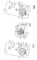
- Figure 1 is a plan view of the seat lock mechanism seen from the electric motor side, in the open position.
- Figure 2 shows the detail of the motor cover that allows the mechanisms below the crown wheel to be seen.
- Figure 3 is a plan view of the mechanism in the closed position.
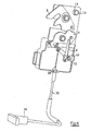
- Figure 4 is a view of the rear side of the mechanism in the lock closed position.
- Figure 5 is another view of the rear side of the mechanism in the lock closed position.
- In accordance with Figures 1 and 4, we can appreciate the casing (1) on which the bearings (7), the trigger (3) and the pawl (4) are mounted and are connected with each other. The trigger is in a position to allow the entry of the bolt from the vehicle bodywork into the opening (8). The pawl (4) extends in a plane that also contains the trigger (3) in the rear part of the casing (1), and at the central opening (15) undergoes an offset and passes to the front side of the casing where the motor (23) is to be found, and it can be appreciated that its free end is provided with a wheel (5).
- On its takeoff shaft, the motor (23) has a worm screw (27) that moves the toothed crown wheel, causing it to turn. Below this crown wheel (19 - Fig. 2), the cam (20) can be seen, mounted on the same axis as the crown wheel.
- The rear side of the crown wheel is provided with a turret (16) which is housed in a cutout (26) in the cam, giving rise to the idle stroke previously considered. As for the cam, it includes the spring (22) secured by one end to the crown wheel, which is tensed or tightened by the movement of the crown wheel during this idle stroke.
- In this same Figure 2, we can appreciate the position of the two microswitches (24, 24'). One of them (24') is connected by the most outer end of the cam (20) itself when the assembly is in the closed position. When the cam turns, the wheel (5) of the pawl (4) makes the latter turn until the said wheel travels along the profile of the cam until it occupies the position of the most outer part of the said cam, with the pawl making contact with the other switch, as shown in Figure 1.
- From Figure 3, it is possible to appreciate the closed position of the mechanism, with the lower end of the pawl distant from the switch (24) and the trigger (3) closing over the bolt lodged in the opening (8).
- The turning actions of the motor in one direction or the other bring about the movement of the pawl in order to achieve the resulting turning of the trigger. These movements of the motor, as stated previously, are carried out from a position which is usually distant from the lock itself, for example on the dashboard or in the driver's side door, where the driver can operate the system.
- According to Figures 4 and 5, we can observe the position of the rocker part (10) used for opening the boot connected to the cable (28), which at its outlet is clamped and led into the interior of the duct (25) to the end (26) located in the rear part of the seat back. The spring for opening is connected onto the rivet (12).
- This rocker part is provided with a cutout (29) in which the lower end of the mechanical arm (9), for manual opening, moves. When the electrical operating system is in movement, this cutout enables the turning of the pawl (4) and consequently of the arm (9) not to have an influence on the rocker part, as the arm (9) travels freely inside this cutout (29).
- However, when the electric operating system is not working, due to voltage failure, and when the cable (28) is pulled in the closed position shown in Figure 5, the rocker part moves the arm (9) and this makes the pawl (4) turn, thus managing to release the trigger (3) and move it to the open position shown in Figure 4.
Claims (5)
- Rear seat lock, particularly for automobiles and similar, with a casing (1) in which a pawl (4) and a trigger (3) are situated and turn, connected to each other by a spring (17) and whose profiles make different contacts in order to cause the opening or closing of a bolt from the bodywork of the vehicle that becomes housed in an opening (8) in the said casing, by means of the change of position of the trigger in relation to the said opening, which is essentially characterised in that the operating system for the pawl (4) that causes the turning of the trigger (3) in order to open or close the lock, is electric and is usually controlled from a position which is distant or remote from the lock in the rear seat.
- Rear seat lock, in accordance with claim 1, characterised in that an electric motor (23) is used, operated by means of a switch in a position accessible to the driver, and with the lock being without any visible accessories with the exception of the opening (8) for the passage of the bolt from the bodywork of the vehicle and the trigger (3).
- Rear seat lock, particularly for automobiles and similar, in accordance with claim 1, which is characterised in that the casing (1) which is used for the seating and turning for the pawl (4) and the trigger (3) has a stepping that forms two surface areas, one upper area for the trigger and the pawl and another lower area, in which an opening (15) is created in the said stepping, through which a lower end of the pawl, which also has a stepped shape, has access to the lower surface area, and with this end having a wheel (5) that turns, supported on the profile or edge of a cam (20), mounted on an axis over the said lower surface area, and with a toothed crown wheel (19) being situated over this axis and engaged with a worm screw (27) from the electric motor (23) takeoff shaft, in that the cam, in its turning movements, pulls the pawl (4), and having two microswitches (24, 24') connected to the said motor, one operated by the most outer end of the cam and the other by the pawl itself on its wheel reaching the said end of the cam.
- Rear seat lock, in accordance with claim 3, characterised in that the cam (20) has a cutout (26) in which a turret (16) from the toothed crown wheel (19) moves, and in that the cam has a spring (22) secured by one of its ends to the crown wheel.
- Rear seat lock, in accordance with claim 3, characterised in that on the lower side of the casing and at the rear of the position of the motor, crown wheel and cam, the rocker party (10) for opening the boot has a central cutout (29), in which the end of the arm (9) fixed to the pawl (4) moves.
Applications Claiming Priority (1)
| Application Number | Priority Date | Filing Date | Title |
|---|---|---|---|
| PCT/ES2001/000301 WO2003010026A1 (en) | 2001-07-26 | 2001-07-26 | Rear seat lock for vehicles |
Publications (2)
| Publication Number | Publication Date |
|---|---|
| EP1410945A1 true EP1410945A1 (en) | 2004-04-21 |
| EP1410945B1 EP1410945B1 (en) | 2006-02-15 |
Family
ID=8244367
Family Applications (1)
| Application Number | Title | Priority Date | Filing Date |
|---|---|---|---|
| EP01960737A Expired - Lifetime EP1410945B1 (en) | 2001-07-26 | 2001-07-26 | Rear seat lock for vehicles |
Country Status (7)
| Country | Link |
|---|---|
| US (1) | US20050023877A1 (en) |
| EP (1) | EP1410945B1 (en) |
| AT (1) | ATE317778T1 (en) |
| CA (1) | CA2451398A1 (en) |
| DE (1) | DE60117274T2 (en) |
| ES (1) | ES2257432T3 (en) |
| WO (1) | WO2003010026A1 (en) |
Cited By (6)
| Publication number | Priority date | Publication date | Assignee | Title |
|---|---|---|---|---|
| GB2436703A (en) * | 2006-03-31 | 2007-10-03 | Lear Corp | An actuator and latch assembly for a folding seat for a vehicle |
| US7581706B2 (en) | 2006-06-26 | 2009-09-01 | Lear Corporation | Shape memory alloy (SMA) system |
| US7709763B2 (en) | 2007-04-13 | 2010-05-04 | Lear Corporation | Rotational based actuator configured to impart linear movement |
| WO2016142771A1 (en) * | 2015-03-12 | 2016-09-15 | Kiekert Ag | Motor vehicle door lock, particularly a backrest lock on a motor vehicle seat |
| WO2019220051A1 (en) | 2018-05-16 | 2019-11-21 | U-Shin France | Motor vehicle backrest electric lock |
| DE102008064458C5 (en) | 2008-12-19 | 2022-08-11 | Adient Luxembourg Holding S.À R.L. | Latch assembly for a vehicle seat, latch assembly system and method of manufacturing a latch assembly |
Families Citing this family (18)
| Publication number | Priority date | Publication date | Assignee | Title |
|---|---|---|---|---|
| DE10305177B4 (en) * | 2003-02-08 | 2008-01-31 | Keiper Gmbh & Co.Kg | Locking device for a vehicle seat |
| US7377584B2 (en) * | 2003-07-28 | 2008-05-27 | Johnson Controls Technology Company | Articulating high latch for a seat |
| US7614701B2 (en) * | 2004-09-21 | 2009-11-10 | Schukra Of North America | System and method for remote release actuating system |
| DE102004045988B3 (en) * | 2004-09-22 | 2005-12-01 | Faurecia Autositze Gmbh & Co. Kg | Display for signaling the non-locking of a folding backrest of a motor vehicle seat |
| FR2891209A1 (en) | 2005-09-29 | 2007-03-30 | Renault Sas | Locking system for swiveling back of car rear seat comprises hook mounted on either back rest or car bodywork which engages with catch on other components and is released by push button on bodywork which is connected to it by lever system |
| ES2299318B1 (en) | 2005-11-22 | 2009-04-16 | Grupo Antolin-Ingenieria, S.A. | BLOCKING DEVICE FOR A FOLDING REAR SEAT SUPPORT OF A VEHICLE, FOLDING REAR SEAT SUPPORT STRUCTURE AND LOCKING AND UNLOCKING SYSTEM OF A FOLDING REAR SEAT SUPPORT. |
| DE102005057623B3 (en) * | 2005-12-02 | 2007-05-10 | Keiper Gmbh & Co.Kg | Motor vehicle seat, has fitting comprising locking unit and counter unit that work together with locking unit, and control device determining relative position of locking and counter units to check suitable orientation for locking fitting |
| JP4597058B2 (en) * | 2006-01-23 | 2010-12-15 | 三井金属鉱業株式会社 | Vehicle seat lock device |
| KR100794896B1 (en) * | 2006-01-23 | 2008-01-14 | 미츠이 긴조쿠 고교 가부시키가이샤 | Vehicle seat lock |
| FR2900880A1 (en) | 2006-05-10 | 2007-11-16 | Renault Sas | Backrest locking device for motor vehicle, has control unit activating locking unit and integrating with coupling part of button, where control unit presents coupling part conformed to be coupled with coupling part of button |
| DE102009017627A1 (en) | 2009-04-09 | 2010-10-21 | Keiper Gmbh & Co. Kg | Locking device for a vehicle seat |
| JP5922482B2 (en) * | 2012-04-27 | 2016-05-24 | 富士機工株式会社 | Sheet fixing device |
| CN113234661A (en) | 2014-12-18 | 2021-08-10 | 哈佛学院校长同事会 | Method for producing stem cell-derived beta cells and method for using same |
| US11060328B2 (en) * | 2018-05-22 | 2021-07-13 | Kiekert Ag | Latching device for automotive applications |
| US10668836B2 (en) * | 2018-06-27 | 2020-06-02 | Tesla, Inc. | Vehicle seatback latch with remote handle having integrated flag |
| US10703240B2 (en) | 2018-06-27 | 2020-07-07 | Tesla, Inc. | Reduced-component vehicle seatback |
| CZ201937A3 (en) | 2019-01-22 | 2020-04-01 | Brano A.S. | Lock latch operating mechanism |
| KR102233493B1 (en) * | 2019-03-08 | 2021-03-29 | 주식회사 디에스시동탄 | Connecting device for cables |
Family Cites Families (12)
| Publication number | Priority date | Publication date | Assignee | Title |
|---|---|---|---|---|
| US3566703A (en) * | 1968-03-28 | 1971-03-02 | Kent Eng | Latch release operating mechanism |
| US3655240A (en) * | 1970-07-20 | 1972-04-11 | Essex International Inc | Motor actuated seat back latch release mechanism |
| JPS57197381A (en) * | 1981-05-29 | 1982-12-03 | Mitsui Mining & Smelting Co | Lock apparatus |
| JP2707637B2 (en) * | 1988-09-30 | 1998-02-04 | アイシン精機株式会社 | Luggage door lock device |
| JPH0726498B2 (en) * | 1988-11-25 | 1995-03-22 | 株式会社大井製作所 | Locking device for opening / closing body of automobile trunk |
| JP2557005B2 (en) * | 1991-10-15 | 1996-11-27 | 三井金属鉱業株式会社 | Activator block devices such as vehicle trunk doors |
| DE19530726C5 (en) * | 1995-08-18 | 2009-07-02 | Kiekert Ag | Central locking system with identical motor vehicle door locks |
| JP3609217B2 (en) * | 1996-09-30 | 2005-01-12 | 株式会社大井製作所 | Locking device |
| FR2782111B1 (en) * | 1998-08-05 | 2002-12-06 | Valeo Securite Habitacle | IMPROVED ELECTRIC LOCK FOR VEHICLE OPENING ELEMENT |
| DE19916811C1 (en) * | 1999-04-14 | 2000-05-18 | Audi Ag | Actuator for hinged backrest for motor vehicle rear seat has control element mounted in luggage compartment for triggering pivoting of backrest actuated by electric motor. |
| DE19948052A1 (en) * | 1999-10-06 | 2001-04-12 | Mannesmann Vdo Ag | Opening aid for door locks |
| US6557911B2 (en) * | 2001-01-23 | 2003-05-06 | Kiekert Ag | Power-open motor-vehicle door latch |
-
2001
- 2001-07-26 CA CA002451398A patent/CA2451398A1/en not_active Abandoned
- 2001-07-26 US US10/482,123 patent/US20050023877A1/en not_active Abandoned
- 2001-07-26 WO PCT/ES2001/000301 patent/WO2003010026A1/en active IP Right Grant
- 2001-07-26 AT AT01960737T patent/ATE317778T1/en not_active IP Right Cessation
- 2001-07-26 ES ES01960737T patent/ES2257432T3/en not_active Expired - Lifetime
- 2001-07-26 DE DE60117274T patent/DE60117274T2/en not_active Expired - Fee Related
- 2001-07-26 EP EP01960737A patent/EP1410945B1/en not_active Expired - Lifetime
Non-Patent Citations (1)
| Title |
|---|
| See references of WO03010026A1 * |
Cited By (11)
| Publication number | Priority date | Publication date | Assignee | Title |
|---|---|---|---|---|
| GB2436703A (en) * | 2006-03-31 | 2007-10-03 | Lear Corp | An actuator and latch assembly for a folding seat for a vehicle |
| US7556315B2 (en) | 2006-03-31 | 2009-07-07 | Lear Corporation | Latch actuator system |
| US7581706B2 (en) | 2006-06-26 | 2009-09-01 | Lear Corporation | Shape memory alloy (SMA) system |
| US7709763B2 (en) | 2007-04-13 | 2010-05-04 | Lear Corporation | Rotational based actuator configured to impart linear movement |
| DE102008064458C5 (en) | 2008-12-19 | 2022-08-11 | Adient Luxembourg Holding S.À R.L. | Latch assembly for a vehicle seat, latch assembly system and method of manufacturing a latch assembly |
| WO2016142771A1 (en) * | 2015-03-12 | 2016-09-15 | Kiekert Ag | Motor vehicle door lock, particularly a backrest lock on a motor vehicle seat |
| US11208015B2 (en) | 2015-03-12 | 2021-12-28 | Kiekert Ag | Motor vehicle door lock, particularly a backrest lock on a motor vehicle seat |
| WO2019220051A1 (en) | 2018-05-16 | 2019-11-21 | U-Shin France | Motor vehicle backrest electric lock |
| FR3081178A1 (en) * | 2018-05-16 | 2019-11-22 | U-Shin France | ELECTRICAL BACKREST OF MOTOR VEHICLE FOLDER |
| JP2021524413A (en) * | 2018-05-16 | 2021-09-13 | ユーシン、フランス | Electric latch on the backrest of a car |
| US11654801B2 (en) | 2018-05-16 | 2023-05-23 | U-Shin France | Electric latch of a motor vehicle backrest |
Also Published As
| Publication number | Publication date |
|---|---|
| DE60117274D1 (en) | 2006-04-20 |
| EP1410945B1 (en) | 2006-02-15 |
| WO2003010026A1 (en) | 2003-02-06 |
| DE60117274T2 (en) | 2006-10-26 |
| ES2257432T3 (en) | 2006-08-01 |
| US20050023877A1 (en) | 2005-02-03 |
| CA2451398A1 (en) | 2003-02-06 |
| ATE317778T1 (en) | 2006-03-15 |
Similar Documents
| Publication | Publication Date | Title |
|---|---|---|
| EP1410945B1 (en) | Rear seat lock for vehicles | |
| US9534427B2 (en) | Motor vehicle door closure | |
| EP2862994B1 (en) | Power release double-locking latch | |
| US4322959A (en) | Locking means for a trunk in an automobile | |
| EP1375794A2 (en) | Inertia locking mechanism | |
| JP6717912B2 (en) | Outer door handle mechanism for automobile | |
| US20180080266A1 (en) | Locking device for a vehicle door, and method | |
| JPH09105262A (en) | Central locking device with automobile door lock having samestructure | |
| US20030116977A1 (en) | Motor vehicle doorlock with combined central locking and opening actuator | |
| KR20030011283A (en) | Access system for a vehicle | |
| US4225008A (en) | Theft-proof system for motor vehicles | |
| EP3268245B1 (en) | Motor vehicle door lock, particularly a backrest lock on a motor vehicle seat | |
| US2339170A (en) | Automobile door lock control device | |
| CN113107289B (en) | Electric door latch apparatus for vehicle | |
| US20230074045A1 (en) | Electrically actuatable motor vehicle lock | |
| CN1774554A (en) | Motor vehicle with central locking | |
| US3339976A (en) | Automobile seat backrest locking device | |
| GB2335946A (en) | Motor vehicle door lock with anti-theft system | |
| US4157478A (en) | Automobile theft prevention system | |
| US4839532A (en) | Control system for vehicular passive seat belt arrangement | |
| EP3587715B1 (en) | A method and a system for unlocking a hood of a vehicle | |
| US3054282A (en) | Vehicle door lock safety device | |
| CN112154248B (en) | Emergency actuating device | |
| KR0149072B1 (en) | Preventive device of starting when a car's door is to be open | |
| US3612588A (en) | Automobile door lock |
Legal Events
| Date | Code | Title | Description |
|---|---|---|---|
| PUAI | Public reference made under article 153(3) epc to a published international application that has entered the european phase |
Free format text: ORIGINAL CODE: 0009012 |
|
| 17P | Request for examination filed |
Effective date: 20040115 |
|
| AK | Designated contracting states |
Kind code of ref document: A1 Designated state(s): AT BE CH CY DE DK ES FI FR GB GR IE IT LI LU MC NL PT SE TR |
|
| AX | Request for extension of the european patent |
Extension state: AL LT LV MK RO SI |
|
| 17Q | First examination report despatched |
Effective date: 20050215 |
|
| GRAP | Despatch of communication of intention to grant a patent |
Free format text: ORIGINAL CODE: EPIDOSNIGR1 |
|
| GRAS | Grant fee paid |
Free format text: ORIGINAL CODE: EPIDOSNIGR3 |
|
| GRAA | (expected) grant |
Free format text: ORIGINAL CODE: 0009210 |
|
| AK | Designated contracting states |
Kind code of ref document: B1 Designated state(s): AT BE CH CY DE DK ES FI FR GB GR IE IT LI LU MC NL PT SE TR |
|
| PG25 | Lapsed in a contracting state [announced via postgrant information from national office to epo] |
Ref country code: IT Free format text: LAPSE BECAUSE OF FAILURE TO SUBMIT A TRANSLATION OF THE DESCRIPTION OR TO PAY THE FEE WITHIN THE PRESCRIBED TIME-LIMIT;WARNING: LAPSES OF ITALIAN PATENTS WITH EFFECTIVE DATE BEFORE 2007 MAY HAVE OCCURRED AT ANY TIME BEFORE 2007. THE CORRECT EFFECTIVE DATE MAY BE DIFFERENT FROM THE ONE RECORDED. Effective date: 20060215 Ref country code: FI Free format text: LAPSE BECAUSE OF FAILURE TO SUBMIT A TRANSLATION OF THE DESCRIPTION OR TO PAY THE FEE WITHIN THE PRESCRIBED TIME-LIMIT Effective date: 20060215 Ref country code: LI Free format text: LAPSE BECAUSE OF FAILURE TO SUBMIT A TRANSLATION OF THE DESCRIPTION OR TO PAY THE FEE WITHIN THE PRESCRIBED TIME-LIMIT Effective date: 20060215 Ref country code: BE Free format text: LAPSE BECAUSE OF FAILURE TO SUBMIT A TRANSLATION OF THE DESCRIPTION OR TO PAY THE FEE WITHIN THE PRESCRIBED TIME-LIMIT Effective date: 20060215 Ref country code: AT Free format text: LAPSE BECAUSE OF FAILURE TO SUBMIT A TRANSLATION OF THE DESCRIPTION OR TO PAY THE FEE WITHIN THE PRESCRIBED TIME-LIMIT Effective date: 20060215 Ref country code: CH Free format text: LAPSE BECAUSE OF FAILURE TO SUBMIT A TRANSLATION OF THE DESCRIPTION OR TO PAY THE FEE WITHIN THE PRESCRIBED TIME-LIMIT Effective date: 20060215 Ref country code: NL Free format text: LAPSE BECAUSE OF FAILURE TO SUBMIT A TRANSLATION OF THE DESCRIPTION OR TO PAY THE FEE WITHIN THE PRESCRIBED TIME-LIMIT Effective date: 20060215 |
|
| REG | Reference to a national code |
Ref country code: GB Ref legal event code: FG4D Ref country code: CH Ref legal event code: EP |
|
| REG | Reference to a national code |
Ref country code: IE Ref legal event code: FG4D |
|
| REF | Corresponds to: |
Ref document number: 60117274 Country of ref document: DE Date of ref document: 20060420 Kind code of ref document: P |
|
| PG25 | Lapsed in a contracting state [announced via postgrant information from national office to epo] |
Ref country code: SE Free format text: LAPSE BECAUSE OF FAILURE TO SUBMIT A TRANSLATION OF THE DESCRIPTION OR TO PAY THE FEE WITHIN THE PRESCRIBED TIME-LIMIT Effective date: 20060515 Ref country code: DK Free format text: LAPSE BECAUSE OF FAILURE TO SUBMIT A TRANSLATION OF THE DESCRIPTION OR TO PAY THE FEE WITHIN THE PRESCRIBED TIME-LIMIT Effective date: 20060515 |
|
| PGFP | Annual fee paid to national office [announced via postgrant information from national office to epo] |
Ref country code: GB Payment date: 20060712 Year of fee payment: 6 |
|
| PG25 | Lapsed in a contracting state [announced via postgrant information from national office to epo] |
Ref country code: PT Free format text: LAPSE BECAUSE OF FAILURE TO SUBMIT A TRANSLATION OF THE DESCRIPTION OR TO PAY THE FEE WITHIN THE PRESCRIBED TIME-LIMIT Effective date: 20060717 |
|
| PG25 | Lapsed in a contracting state [announced via postgrant information from national office to epo] |
Ref country code: IE Free format text: LAPSE BECAUSE OF NON-PAYMENT OF DUE FEES Effective date: 20060726 |
|
| PG25 | Lapsed in a contracting state [announced via postgrant information from national office to epo] |
Ref country code: MC Free format text: LAPSE BECAUSE OF NON-PAYMENT OF DUE FEES Effective date: 20060731 |
|
| NLV1 | Nl: lapsed or annulled due to failure to fulfill the requirements of art. 29p and 29m of the patents act | ||
| REG | Reference to a national code |
Ref country code: ES Ref legal event code: FG2A Ref document number: 2257432 Country of ref document: ES Kind code of ref document: T3 |
|
| REG | Reference to a national code |
Ref country code: CH Ref legal event code: PL |
|
| ET | Fr: translation filed | ||
| PLBE | No opposition filed within time limit |
Free format text: ORIGINAL CODE: 0009261 |
|
| STAA | Information on the status of an ep patent application or granted ep patent |
Free format text: STATUS: NO OPPOSITION FILED WITHIN TIME LIMIT |
|
| 26N | No opposition filed |
Effective date: 20061116 |
|
| PGFP | Annual fee paid to national office [announced via postgrant information from national office to epo] |
Ref country code: ES Payment date: 20070703 Year of fee payment: 7 |
|
| PGFP | Annual fee paid to national office [announced via postgrant information from national office to epo] |
Ref country code: DE Payment date: 20070730 Year of fee payment: 7 |
|
| GBPC | Gb: european patent ceased through non-payment of renewal fee |
Effective date: 20070726 |
|
| PG25 | Lapsed in a contracting state [announced via postgrant information from national office to epo] |
Ref country code: GR Free format text: LAPSE BECAUSE OF FAILURE TO SUBMIT A TRANSLATION OF THE DESCRIPTION OR TO PAY THE FEE WITHIN THE PRESCRIBED TIME-LIMIT Effective date: 20060516 |
|
| PGFP | Annual fee paid to national office [announced via postgrant information from national office to epo] |
Ref country code: FR Payment date: 20070427 Year of fee payment: 7 |
|
| PG25 | Lapsed in a contracting state [announced via postgrant information from national office to epo] |
Ref country code: GB Free format text: LAPSE BECAUSE OF NON-PAYMENT OF DUE FEES Effective date: 20070726 |
|
| PG25 | Lapsed in a contracting state [announced via postgrant information from national office to epo] |
Ref country code: TR Free format text: LAPSE BECAUSE OF FAILURE TO SUBMIT A TRANSLATION OF THE DESCRIPTION OR TO PAY THE FEE WITHIN THE PRESCRIBED TIME-LIMIT Effective date: 20060215 Ref country code: LU Free format text: LAPSE BECAUSE OF NON-PAYMENT OF DUE FEES Effective date: 20060726 |
|
| PG25 | Lapsed in a contracting state [announced via postgrant information from national office to epo] |
Ref country code: CY Free format text: LAPSE BECAUSE OF FAILURE TO SUBMIT A TRANSLATION OF THE DESCRIPTION OR TO PAY THE FEE WITHIN THE PRESCRIBED TIME-LIMIT Effective date: 20060215 |
|
| PG25 | Lapsed in a contracting state [announced via postgrant information from national office to epo] |
Ref country code: DE Free format text: LAPSE BECAUSE OF NON-PAYMENT OF DUE FEES Effective date: 20090203 |
|
| REG | Reference to a national code |
Ref country code: FR Ref legal event code: ST Effective date: 20090331 |
|
| PG25 | Lapsed in a contracting state [announced via postgrant information from national office to epo] |
Ref country code: FR Free format text: LAPSE BECAUSE OF NON-PAYMENT OF DUE FEES Effective date: 20080731 |
|
| REG | Reference to a national code |
Ref country code: ES Ref legal event code: FD2A Effective date: 20080728 |
|
| PG25 | Lapsed in a contracting state [announced via postgrant information from national office to epo] |
Ref country code: ES Free format text: LAPSE BECAUSE OF NON-PAYMENT OF DUE FEES Effective date: 20080728 |