EP1409797B1 - Trenching machine - Google Patents
Trenching machine Download PDFInfo
- Publication number
- EP1409797B1 EP1409797B1 EP01978001.4A EP01978001A EP1409797B1 EP 1409797 B1 EP1409797 B1 EP 1409797B1 EP 01978001 A EP01978001 A EP 01978001A EP 1409797 B1 EP1409797 B1 EP 1409797B1
- Authority
- EP
- European Patent Office
- Prior art keywords
- main frame
- trenching arm
- cutting
- trenching
- arm
- Prior art date
- Legal status (The legal status is an assumption and is not a legal conclusion. Google has not performed a legal analysis and makes no representation as to the accuracy of the status listed.)
- Expired - Lifetime
Links
Images


Classifications
-
- E—FIXED CONSTRUCTIONS
- E02—HYDRAULIC ENGINEERING; FOUNDATIONS; SOIL SHIFTING
- E02F—DREDGING; SOIL-SHIFTING
- E02F5/00—Dredgers or soil-shifting machines for special purposes
- E02F5/02—Dredgers or soil-shifting machines for special purposes for digging trenches or ditches
- E02F5/04—Dredgers or soil-shifting machines for special purposes for digging trenches or ditches with digging screws
-
- E—FIXED CONSTRUCTIONS
- E02—HYDRAULIC ENGINEERING; FOUNDATIONS; SOIL SHIFTING
- E02F—DREDGING; SOIL-SHIFTING
- E02F3/00—Dredgers; Soil-shifting machines
- E02F3/04—Dredgers; Soil-shifting machines mechanically-driven
- E02F3/06—Dredgers; Soil-shifting machines mechanically-driven with digging screws
Definitions
- the present invention relates to a trenching machine for cutting a trench for insitu casting of a concrete retaining wall.
- US Patent No. 4199033 describes an augering apparatus intended for attachment as an accessory to a hydraulically operated boom of a backhoe or the like. This document forms the basis for the preamble of claim 1.
- the present invention was developed with a view to providing a trenching machine that employs a more efficient excavating technique.
- a trenching arm used for cutting a trench for insitu casting of a concrete retaining wall, the trenching arm comprising:
- said cutting auger is one of a plurality of cutting augers rotatably mounted side by side on the main frame for cutting a trench of increased width.
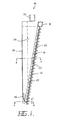
- a preferred embodiment of the trenching arm 10 as illustrated in Figures 1 to 4 comprises a cutting auger 12 having a generally helical cutting blade 14 for cutting into soil and transporting the soil to the surface.
- the cutting auger 12 is rotatably mounted on a main frame 16 which is designed to be carried in a substantially vertical orientation by a support vehicle (not illustrated).
- a hydraulic motor 18 is mechanically coupled to the cutting auger 12 for rotating the cutting auger.
- the helical cutting blade 14 is formed from a series of blade segments supported on a common drive shaft 20 so as to form one continuous helical flight.
- the cutting blade 14 may also be formed as a discontinuous series of helical flights.
- Drive shaft 20 is typically a hollow shaft having an outer diameter of approximately 100mm to 120mm, whilst the flights of the cutting blade 14 are typically between 70mm to 100mm wide, making a total outer diameter of the cutting blade of approximately 240mm to 320mm.
- the full length of the helical cutting blade of this embodiment is approximately 6.5m.
- Drive shaft 20 is rotatably supported on the main frame 16 by means of a plurality of sealed, heavy duty bearings held on support brackets 22.
- a pair of substantially parallel, planar shield members 24 are mounted either side of the main frame 16 and are designed to act as a temporary form work for holding open the side walls of the trench created behind the trenching arm in use.
- the main frame 16 is preferably provided with a rotatable coupling 26 for mechanically coupling the trenching arm to a boom 28 (see Figures 5 and 6 ) carried by a support vehicle.
- the trenching arm 10 can be made to travel in different directions to form a continuous trench for casting angled, curved or even circular walls.
- the trenching arm could be used for casting, for example, a retaining wall for a lined pit or shaft.
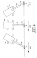
- the boom 28, to which the trenching arm 10 is rotatably coupled is an extendible boom as illustrated more clearly in Figures 3 and 4 .
- the boom 28 preferably comprises a first boom segment 50 mechanically coupled at one end to a work arm 52 of a support vehicle, for example, excavator 54.
- a second boom segment 56 is telescopically received within the first boom segment 50, and comprises an hydraulic ram 58 received within the hollow interior of the first boom segment 50 and connected at one end 60 thereto, the other end of the ram 58 being connected to a sleeve 62 of the second boom segment 56.
- Sleeve 62 is mechanically coupled to a coupling head 64, to which the trenching arm 10 is rotatably coupled, at two pivot points 66 and 68.
- Sleeve 62 is coupled to the first pivot point 66 adjacent a lower edge of the coupling head 64 at a fixed distance, whereas it is coupled to the second pivot point 68 by a variable distance controlled by a small hydraulic ram 70.
- Hydraulic ram 70 is pivotally mounted on the sleeve 62 and can be operated independently of the ram 58. Extension and retraction of the ram 70 results in a tilting of the coupling head 64, (and thereby also trenching arm 10) in a plane which passes through the boom 28.
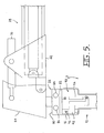
- Rotatable coupling 26 for mechanically coupling the trenching arm to the coupling head 64 of the boom 28 is shown more clearly in Figures 5 and 6 .
- Rotatable coupling 26 comprises a hydraulically actuated turntable 80 rotatably coupled to a mounting plate 82 provided at the top end of the trenching arm 10.
- a pair of hydraulic actuators 84 offset with respect to the centre of rotation of the turntable 80, are provided to actuate the rotatable coupling in either rotational direction. This greatly enhances the utility of the trenching arm 10, as it permits the trenching arm to be moved in directions other than parallel to the direction of travel of the support vehicle.
- a self-levelling mechanism 90 for adjusting the angle at which the trenching arm 10 is carried by the boom 28 so as to maintain a prescribed level and depth of trench, particularly on a sloping grade.
- the self-levelling mechanism 90 comprises two sub-assemblies for providing a levelling action in two perpendicular planes of movement respectively. Both sub-assemblies of the self-levelling mechanism 90 are preferably housed within a sub-frame 108 that is bolted or welded into a recess provided in the top end of the main frame 16 of the trenching arm 10.
- this permits the self-levelling mechanism 90 to be readily removed for maintenance purposes, or replaced if necessary, without disturbing the structural integrity of the trenching arm 10.
- the first sub-assembly of the self-levelling mechanism 90 is shown in Figure 5 , and is designed to provide a levelling or tilting action in a plane perpendicular to the direction of travel of the trenching arm 10.
- the first sub-assembly comprises a support arm 92 that is fixed at one end to the sub-frame 108 of the trenching arm 10 so as to immoveable relative thereto.
- the other end of the support arm 92 has a hydraulic actuator 94 connected at one end thereto.
- the other end of the hydraulic actuator 94 is pivotally connected to the mounting plate 82, which is in turn pivotally coupled to the sub-frame 108 at pivot point 96.
- mounting plate 82 is rotatably coupled to the turntable 80.
- the second sub-assembly of the self-levelling mechanism 90 is illustrated in Figure 6 .
- the second sub-assembly also comprises a pair of hydraulic actuators 98 pivotally connected at their lower ends to the sub-frame 108 of the trenching arm 10, and pivotally connected at their upper ends to a pivot arm 100.
- Pivot arm 100 is pivotally mounted on the main frame 16 of the trenching arm 10 by means of a pivot shaft 104 that is mounted in a pair of bearing mounting blocks 102 (only one mounting block 102 is visible, as the other one is located directly behind it on the other side of the main frame 16).
- Bearing mounting blocks 102 are fixed to the main frame 16 at respective ends of the pivot shaft 104 that extends from side to side the full width of the main frame 16. Pivot shaft 104 effectively acts to locks the sub-frame 108 into the main frame 16. When either one or both of hydraulic actuators 98 are activated, the main frame 16 of the trenching arm 10 will be caused to swivel or tilt on pivot shaft 104 in the direction of arrows BB shown in Figure 6 . It will understood therefore that the two sub-assemblies of the self-levelling mechanism 90 effectively act in a similar manner to the perpendicular cross-over shafts in a universal joint to create universal movement.
- the self-levelling mechanism 90 may be manually controlled to adjust the angle of inclination with respect to the vertical of the trenching arm 10 in use, or alternatively it may be automatically controlled by a pre-programmed microprocessor-controlled servo control system. In either case, the main function of the self-levelling mechanism is to permit the angle at which the trenching arm 10 is carried on the coupling head 64 to be adjusted as required, to maintain the desired cutting depth, orientation or direction of the helical cutting auger 12 on the trenching arm 10.
- the cutting auger 12 cuts the soil in front of the trenching arm and carries it to the surface, creating a trench behind the main frame that can be filled with concrete to form a retaining wall.
- the concrete can be pumped into the trench simultaneously as the trench is being formed by the trenching arm so that the surrounding soil does not collapse.
- the weight of the concrete behind the trenching arm 10 helps to thrust it forwards in the trench.
- the trenching arm can also be operated to cast a wall below the level of the water table without the use of bentonite (although bentonite may be used if desired).
- the concrete will fill the void behind the trenching arm before the water can, since it is heavier than water and therefore displaces any water that may be present.
- the trenching arm 10 may also be fitted with height adjustable skids or similar depth control means fitted to the shield members 24 and adapted to ride on the top surface of the soil.
- Soil deflecting blades may also be provided adjacent to the front edge of the trenching arm at the soil surface, for pushing soil, lifted to the surface by the cutting auger 12, away from the trench being formed behind the trenching arm.
- the deflecting blades may be formed integral with the level control means or skids.
- a side chute may be provided at the top of the auger arranged to drop the soil a short distance to one side.
- the trenching arm 10 is first raised to a vertical position using boom 28, and then lowered into the ground.
- the weight of the trenching arm 10 may be sufficient in itself to help drive the cutting auger 12 into the soil, or an additional downwards force may be applied via the boom 28.
- the cutting auger 12 may be tilted at an angle that varies from vertical to 45°.
- the line of force of any downwards thrust applied to the trenching arm via rotatable coupling 26 is substantially aligned with the bottom end of the cutting auger 12.
- the support vehicle typically an excavator, then travels forward drawing the trenching arm 10 forwards with it.
- the cutting auger 12 cuts the soil in front of it and carries it to the surface, creating a void 30 behind the main frame 16 which is held open by the shield members 24.
- the concrete can then be poured into the void 30 between the shield members 24 (see Figures 7 and 8 ).
- the concrete slumps into the trench and is then able to provide a counter pressure to the lateral pressure on the walls of the trench to hold it open.
- the weight of the concrete pressing on the rear of the main frame 16 also helps to drive the cutting auger 12 forwards through the soil.
- the main frame 16 may also be provided with a shutter 34, (see Figure 1 ), held in grooves at the back end.
- shutter 34 will allow the new wall to have a square starting face as it prevents the soil from falling into the void created directly behind the cutting auger 12.
- the trenching arm 10 is driven forwards through the soil and concrete pouring has commenced, shutter 34 can be removed as the concrete slump will hold the soil in place.
- Adjacent the bottom end of the trenching arm 10 there is provided a horizontal hinged flap 36 with side walls which is normally held in an upwards position as shown in Figure 1 .
- two vertical hinged flaps 38 (see also Figure 2 ) that are normally closed.
- Flaps 38 are approximately one metre in height and prevent the soil from falling into the void directly behind the cutting auger 12 as the trenching arm is augered downwards into the soil. This void is filled with concrete. As the trenching arm continues downwards into the soil, concrete is being poured into the open space between shield members 24. The concrete will act to stop the soil coming into the back of the open end of the trenching arm. When the trenching arm reaches the required depth full of concrete, the arm can then be moved forward. At the top of the open shield members a small shutter 39 is attached to the back of the shield members, just above the surface of the laid concrete to maintain a head of concrete.
- Flap 36 prevents the concrete from flowing forwards into contact with the bottom end of the cutting auger 12.
- fibreglass or steel fibre can be mixed with the cement.
- reinforcing bars 42 can be placed in the concrete while it is still wet to give lateral strength (see Figure 10 ). If desired blockouts can be inserted, laced to the reinforcing bar, to insert ground anchors at a later stage during construction of the retaining wall (for non-cantilevered walls).
- the helical cutting blade 14 of the cutting auger can be rotated in the reverse direction to refill the void left by the trenching arm, as it is withdrawn, against the finished concrete wall.
- Cutting bits 40 can be welded to the edge of the flights of the cutting blade 14 (see Figure 9 ) for cutting through stiff soils and to reduce wear on the flights. If it is desired to cut a wider trench, a cutting auger of increased diameter may be used, or alternatively two or more cutting augers may be rotatably mounted side by side on the main frame for cutting a trench of increased width.
- the trenching arm can also be used to dig trenches for laying pipes and cables. All such variations and modifications are to be considered within the scope of the present invention, the nature of which is to be determined from the appended claims.
Landscapes
- Engineering & Computer Science (AREA)
- Mechanical Engineering (AREA)
- Mining & Mineral Resources (AREA)
- Civil Engineering (AREA)
- General Engineering & Computer Science (AREA)
- Structural Engineering (AREA)
- Excavating Of Shafts Or Tunnels (AREA)
- Earth Drilling (AREA)
Description
- The present invention relates to a trenching machine for cutting a trench for insitu casting of a concrete retaining wall.
- The technique of continuous casting of a concrete retaining wall, in which a trench is continuously excavated and filled with concrete, is well known. Australian Patent No.
584083 637347 AU 637347 - One of the problems with these prior art trenching machines is that the endless chain type excavator is very expensive to operate and maintain. There are many moving parts that wear out, and the drive needed to keep the endless chain rotating must be quite powerful and robust due to the weight of the moving parts and soil resistance.
-
US Patent No. 4199033 describes an augering apparatus intended for attachment as an accessory to a hydraulically operated boom of a backhoe or the like. This document forms the basis for the preamble of claim 1. - The present invention was developed with a view to providing a trenching machine that employs a more efficient excavating technique.
- Throughout this specification the term "comprising" is used inclusively, in the sense that there may be other features and/or steps included in the invention not expressly defined or comprehended in the features or steps subsequently defined or described. What such other features and/or steps may include will be apparent from the specification read as a whole.
- According to the present invention there is provided a trenching arm used for cutting a trench for insitu casting of a concrete retaining wall, the trenching arm comprising:
- a cutting auger having a substantially helical cutting blade for cutting into soil and transporting the soil to the surface;
- a main frame on which the cutting auger is rotatably mounted, the main frame being adapted to be carried in a generally vertical orientation by a support vehicle; and,
- a motor mechanically coupled to the cutting auger for rotating the cutting auger whereby, in use, as the main frame is driven in a forwards direction the cutting auger cuts the soil in front of it and carries the soil to the surface creating a trench behind the main frame that can be filled with concrete to form a retaining wall;
- characterised in that said main frame is provided with a rotatable coupling for mechanically coupling the trenching arm to a support vehicle such that the trenching arm can be made to travel in different directions relative to the support vehicle;
- and, in that said main frame is provided with a pair of substantially parallel, planar shield members, respectively mounted either side of the main frame and adapted to hold open the side walls of the trench created behind the main frame for concrete to be poured into, wherein the shield members become progressively narrower in a direction away from the rotatable coupling. Preferably the trenching arm further comprises a self-levelling mechanism for adjusting the angle at which the main frame is carried whereby, in use, a prescribed level of trench on a sloping grade can be minimised.
- In another embodiment said cutting auger is one of a plurality of cutting augers rotatably mounted side by side on the main frame for cutting a trench of increased width.
- In order to facilitate a more comprehensive understanding of the nature of the invention, a preferred embodiment of the trenching arm in accordance with the present invention will now be described in detail, by way of example only, with reference to the accompanying drawings, in which:
-
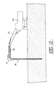
Figure 1 is a side elevation of a preferred embodiment of the trenching arm in accordance with the present invention; -
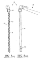
Figure 2(a) is a front elevation of the trenching arm ofFigure 1 ; -
Figure 2(b) is a rear elevation of the trenching arm ofFigure 1 ; -
Figure 3 is a side elevation of an extendable boom for the trenching arm ofFigure 1 ;Figures 4(a), (b) and (c) illustrate extension of the boom ofFigure 3 in different positions;Figure 5 is a partial cut-away end view of a self-levelling mechanism provided within the trenching arm ofFigure 1 ; -
Figure 6 is a partial cut-away side view of the self-levelling mechanism ofFigure 5 ;Figure 7 is a top plan view of the trenching arm ofFigure 1 ; -
Figures 8 and 9 are section views of the trenching arm through the lines A-A and B-B respectively inFigure 1 ; -
Figure 10 is a side elevation of the trenching machine ofFigure 1 shown insitu as used for cutting a trench and casting a concrete retaining wall; and, -
Figures 11 and12 illustrate the trenching arm ofFigure 1 being used to cut a trench and cast a concrete retaining wall. - A preferred embodiment of the trenching
arm 10 as illustrated inFigures 1 to 4 comprises acutting auger 12 having a generallyhelical cutting blade 14 for cutting into soil and transporting the soil to the surface. Thecutting auger 12 is rotatably mounted on amain frame 16 which is designed to be carried in a substantially vertical orientation by a support vehicle (not illustrated). Ahydraulic motor 18 is mechanically coupled to thecutting auger 12 for rotating the cutting auger. - Preferably the
cutting auger 12 is tilted at an angle of between θ = 45° to 90°, more preferably approximately θ = 80° as can be seen most clearly inFigure 1 . Typically, thehelical cutting blade 14 is formed from a series of blade segments supported on acommon drive shaft 20 so as to form one continuous helical flight. However, thecutting blade 14 may also be formed as a discontinuous series of helical flights.Drive shaft 20 is typically a hollow shaft having an outer diameter of approximately 100mm to 120mm, whilst the flights of thecutting blade 14 are typically between 70mm to 100mm wide, making a total outer diameter of the cutting blade of approximately 240mm to 320mm. The full length of the helical cutting blade of this embodiment is approximately 6.5m.Drive shaft 20 is rotatably supported on themain frame 16 by means of a plurality of sealed, heavy duty bearings held onsupport brackets 22. A pair of substantially parallel,planar shield members 24 are mounted either side of themain frame 16 and are designed to act as a temporary form work for holding open the side walls of the trench created behind the trenching arm in use. - The
main frame 16 is preferably provided with arotatable coupling 26 for mechanically coupling the trenching arm to a boom 28 (seeFigures 5 and6 ) carried by a support vehicle. In this way, the trenchingarm 10 can be made to travel in different directions to form a continuous trench for casting angled, curved or even circular walls. Hence, the trenching arm could be used for casting, for example, a retaining wall for a lined pit or shaft. - Advantageously the
boom 28, to which the trenchingarm 10 is rotatably coupled, is an extendible boom as illustrated more clearly inFigures 3 and4 . As shown inFigure 3 , theboom 28 preferably comprises afirst boom segment 50 mechanically coupled at one end to awork arm 52 of a support vehicle, for example,excavator 54. Asecond boom segment 56 is telescopically received within thefirst boom segment 50, and comprises anhydraulic ram 58 received within the hollow interior of thefirst boom segment 50 and connected at oneend 60 thereto, the other end of theram 58 being connected to asleeve 62 of thesecond boom segment 56.Sleeve 62 is mechanically coupled to acoupling head 64, to which the trenchingarm 10 is rotatably coupled, at twopivot points Sleeve 62 is coupled to thefirst pivot point 66 adjacent a lower edge of thecoupling head 64 at a fixed distance, whereas it is coupled to thesecond pivot point 68 by a variable distance controlled by a smallhydraulic ram 70.Hydraulic ram 70 is pivotally mounted on thesleeve 62 and can be operated independently of theram 58. Extension and retraction of theram 70 results in a tilting of thecoupling head 64, (and thereby also trenching arm 10) in a plane which passes through theboom 28. This means, for example, when the trenchingarm 10 is being lifted byboom 28, it can be maintained in a substantially vertical orientation as the height of thecoupling head 64 above the ground increases. In such a lifting operation, it may also be necessary to extendboom 28 by actuating thehydraulic ram 58. The ability to increase and decrease the length ofextendible boom 28 is also very useful when constructing a retaining wall within an area where theexcavator 54 has restricted manoeuvrability. In normal use, the trenchingarm 10 would be supported some distance from and adjacent to theexcavator 54 via thework arm 52 as shown inFigure 4(b) . However, when extending the wall, for example, into a corner, where theexcavator 54 may not be able to travel, the reach of theboom 28 may be extended as shown inFigures 4(a) and (c) . - The
rotatable coupling 26 for mechanically coupling the trenching arm to thecoupling head 64 of theboom 28 is shown more clearly inFigures 5 and6 .Rotatable coupling 26 comprises a hydraulically actuatedturntable 80 rotatably coupled to amounting plate 82 provided at the top end of the trenchingarm 10. A pair ofhydraulic actuators 84, offset with respect to the centre of rotation of theturntable 80, are provided to actuate the rotatable coupling in either rotational direction. This greatly enhances the utility of the trenchingarm 10, as it permits the trenching arm to be moved in directions other than parallel to the direction of travel of the support vehicle. - Also shown in
Figures 5 and6 is a self-levelling mechanism 90 for adjusting the angle at which the trenchingarm 10 is carried by theboom 28 so as to maintain a prescribed level and depth of trench, particularly on a sloping grade. The self-levelling mechanism 90 comprises two sub-assemblies for providing a levelling action in two perpendicular planes of movement respectively. Both sub-assemblies of the self-levellingmechanism 90 are preferably housed within asub-frame 108 that is bolted or welded into a recess provided in the top end of themain frame 16 of thetrenching arm 10. Advantageously, this permits the self-levellingmechanism 90 to be readily removed for maintenance purposes, or replaced if necessary, without disturbing the structural integrity of thetrenching arm 10. The first sub-assembly of the self-levellingmechanism 90 is shown inFigure 5 , and is designed to provide a levelling or tilting action in a plane perpendicular to the direction of travel of thetrenching arm 10. The first sub-assembly comprises asupport arm 92 that is fixed at one end to thesub-frame 108 of thetrenching arm 10 so as to immoveable relative thereto. The other end of thesupport arm 92 has ahydraulic actuator 94 connected at one end thereto. The other end of thehydraulic actuator 94 is pivotally connected to the mountingplate 82, which is in turn pivotally coupled to thesub-frame 108 atpivot point 96. As noted above, mountingplate 82 is rotatably coupled to theturntable 80. With this arrangement, activation of thehydraulic actuator 94 will result in a tilting motion of thetrenching arm 10 in the direction of arrow AA shown inFigure 5 . Preferably, there are a pair of saidhydraulic actuators 94, withcorresponding support arms 92, however only one is visible inFigure 5 as the other is mounted directly behind it but spaced apart from it. - The second sub-assembly of the self-levelling
mechanism 90 is illustrated inFigure 6 . As with the first sub-assembly, the second sub-assembly also comprises a pair ofhydraulic actuators 98 pivotally connected at their lower ends to thesub-frame 108 of thetrenching arm 10, and pivotally connected at their upper ends to apivot arm 100.Pivot arm 100 is pivotally mounted on themain frame 16 of thetrenching arm 10 by means of apivot shaft 104 that is mounted in a pair of bearing mounting blocks 102 (only onemounting block 102 is visible, as the other one is located directly behind it on the other side of the main frame 16).Bearing mounting blocks 102 are fixed to themain frame 16 at respective ends of thepivot shaft 104 that extends from side to side the full width of themain frame 16.Pivot shaft 104 effectively acts to locks thesub-frame 108 into themain frame 16. When either one or both ofhydraulic actuators 98 are activated, themain frame 16 of thetrenching arm 10 will be caused to swivel or tilt onpivot shaft 104 in the direction of arrows BB shown inFigure 6 . It will understood therefore that the two sub-assemblies of the self-levellingmechanism 90 effectively act in a similar manner to the perpendicular cross-over shafts in a universal joint to create universal movement. - The self-levelling
mechanism 90 may be manually controlled to adjust the angle of inclination with respect to the vertical of thetrenching arm 10 in use, or alternatively it may be automatically controlled by a pre-programmed microprocessor-controlled servo control system. In either case, the main function of the self-levelling mechanism is to permit the angle at which thetrenching arm 10 is carried on thecoupling head 64 to be adjusted as required, to maintain the desired cutting depth, orientation or direction of thehelical cutting auger 12 on thetrenching arm 10. Thus, for example, when the end of a trench has been reached, and thetrenching arm 10 needs to be lifted upwards out of the trench, it is preferable at that point to change the angle of inclination of the cuttingauger 12 to as near as possible to the vertical so that the end face of the trench, and therefore of the retaining wall formed therein, will be as close as possible to the vertical. - In use, as the
main frame 16 is driven in a forwards direction through the soil, the cuttingauger 12 cuts the soil in front of the trenching arm and carries it to the surface, creating a trench behind the main frame that can be filled with concrete to form a retaining wall. Preferably, the concrete can be pumped into the trench simultaneously as the trench is being formed by the trenching arm so that the surrounding soil does not collapse. Advantageously, the weight of the concrete behind thetrenching arm 10 helps to thrust it forwards in the trench. The trenching arm can also be operated to cast a wall below the level of the water table without the use of bentonite (although bentonite may be used if desired). The concrete will fill the void behind the trenching arm before the water can, since it is heavier than water and therefore displaces any water that may be present. Thetrenching arm 10 may also be fitted with height adjustable skids or similar depth control means fitted to theshield members 24 and adapted to ride on the top surface of the soil. Soil deflecting blades (not illustrated) may also be provided adjacent to the front edge of the trenching arm at the soil surface, for pushing soil, lifted to the surface by the cuttingauger 12, away from the trench being formed behind the trenching arm. The deflecting blades may be formed integral with the level control means or skids. Alternatively, or in addition, a side chute may be provided at the top of the auger arranged to drop the soil a short distance to one side. - Operation of the
trenching arm 10 will now be described with reference toFigures 10 ,11 and12 . - In use, the
trenching arm 10 is first raised to a verticalposition using boom 28, and then lowered into the ground. The weight of thetrenching arm 10 may be sufficient in itself to help drive the cuttingauger 12 into the soil, or an additional downwards force may be applied via theboom 28. As the cuttingauger 12 is on an 80° angle it digs the soil away from the bottom of the trenching arm, which allows the arm to dig itself into the ground. As the cuttingauger 12 extends down and under the rearwards projectingshield members 24, soil resistance is reduced when digging down vertically. Depending on soil conditions, the cuttingauger 12 may be tilted at an angle that varies from vertical to 45°. As can be seen inFigure 10 , the line of force of any downwards thrust applied to the trenching arm viarotatable coupling 26 is substantially aligned with the bottom end of the cuttingauger 12. - The support vehicle, typically an excavator, then travels forward drawing the
trenching arm 10 forwards with it. As the trenching arm is forced forwards in a horizontal direction, the cuttingauger 12 cuts the soil in front of it and carries it to the surface, creating a void 30 behind themain frame 16 which is held open by theshield members 24. The concrete can then be poured into the void 30 between the shield members 24 (seeFigures 7 and 8 ). As the trenching arm travels forwards through the soil, the concrete slumps into the trench and is then able to provide a counter pressure to the lateral pressure on the walls of the trench to hold it open. The weight of the concrete pressing on the rear of themain frame 16 also helps to drive the cuttingauger 12 forwards through the soil. Once the concrete has formed a continuous column from top to bottom at the full depth required, the retaining wall can be continuously formed by the trenching arm travelling forwards and the concrete being poured in continuously behind the trenching arm at the same time. - The
main frame 16 may also be provided with ashutter 34, (seeFigure 1 ), held in grooves at the back end. When starting the concrete pour, shutter 34 will allow the new wall to have a square starting face as it prevents the soil from falling into the void created directly behind the cuttingauger 12. When the cuttingauger 12 has reached the prescribed depth, thetrenching arm 10 is driven forwards through the soil and concrete pouring has commenced,shutter 34 can be removed as the concrete slump will hold the soil in place. Adjacent the bottom end of thetrenching arm 10 there is provided a horizontal hingedflap 36 with side walls which is normally held in an upwards position as shown inFigure 1 . There are also provided two vertical hinged flaps 38 (see alsoFigure 2 ) that are normally closed.Flaps 38 are approximately one metre in height and prevent the soil from falling into the void directly behind the cuttingauger 12 as the trenching arm is augered downwards into the soil. This void is filled with concrete. As the trenching arm continues downwards into the soil, concrete is being poured into the open space betweenshield members 24. The concrete will act to stop the soil coming into the back of the open end of the trenching arm. When the trenching arm reaches the required depth full of concrete, the arm can then be moved forward. At the top of the open shield members asmall shutter 39 is attached to the back of the shield members, just above the surface of the laid concrete to maintain a head of concrete. As the trenching arm moves forward the twoflaps 38 at the bottom of the shield will open out with the force of the concrete, also allowing theflap 36 to fall back and lay on the bottom of the trench.Flap 36 prevents the concrete from flowing forwards into contact with the bottom end of the cuttingauger 12. - To give strength to the finished concrete retaining wall, fibreglass or steel fibre can be mixed with the cement. In addition, reinforcing
bars 42 can be placed in the concrete while it is still wet to give lateral strength (seeFigure 10 ). If desired blockouts can be inserted, laced to the reinforcing bar, to insert ground anchors at a later stage during construction of the retaining wall (for non-cantilevered walls). - When removing the trenching arm from the ground at completion of concreting, the
helical cutting blade 14 of the cutting auger can be rotated in the reverse direction to refill the void left by the trenching arm, as it is withdrawn, against the finished concrete wall. - Using a cutting auger to excavate the soil is a much more efficient method of excavation. It significantly reduces the soil friction as the trenching arm travels through the soil. The narrowing of the
shield members 24 towards the bottom of the trenching arm also minimises the surface area subject to lateral soil pressure, further helping to reduce soil friction as the trenching arm is forced through the soil. Cuttingbits 40 can be welded to the edge of the flights of the cutting blade 14 (seeFigure 9 ) for cutting through stiff soils and to reduce wear on the flights. If it is desired to cut a wider trench, a cutting auger of increased diameter may be used, or alternatively two or more cutting augers may be rotatably mounted side by side on the main frame for cutting a trench of increased width. - Now that a preferred embodiment of the trenching arm has been described in detail, it will be appreciated that it provides a number of significant advantages over prior art trenching machines, including the following:
- (i) fewer moving parts, means less wear and reduced maintenance costs;
- (ii) helical cutting auger requires less torque to rotate than a toothed chain-type excavator, giving reduced operating costs and improved efficiency;
- (iii) reduced lateral surface area and less aggressive cutting action reduces energy losses due to soil friction;
- (iv) overall weight and size of the trenching arm is reduced making it easier to transport and manoeuvre; and,
- (v) cost of manufacturing the trenching arm is also significantly reduced.
- Numerous variations and modifications will suggest themselves to persons skilled in the excavating arts, in addition to those already described, without departing from the basic inventive concepts. The trenching arm can also be used to dig trenches for laying pipes and cables. All such variations and modifications are to be considered within the scope of the present invention, the nature of which is to be determined from the appended claims.
Claims (8)
- A trenching arm (10) used for cutting a trench for insitu casting of a concrete retaining wall, the trenching arm (10) comprising:a cutting auger (12) having a substantially helical cutting blade (14) for cutting into soil and transporting the soil to the surface;a main frame (16) on which the cutting auger (12) is rotatably mounted, the main frame being adapted to be carried in a generally vertical orientation by a support vehicle; and,a motor (18) mechanically coupled to the cutting auger (12) for rotating the cutting auger whereby, in use, as the main frame (16) is driven in a forwards direction the cutting auger cuts the soil in front of it and carries the soil to the surface creating a trench behind the main frame that can be filled with concrete to form a retaining wall;said main frame (16) being provided with a rotatable coupling (26) for mechanically coupling the trenching arm (10) to a support vehicle such that the trenching arm (10) can be made to travel in a variety of directions relative to the support vehicle;and characterised by the main frame (16) being provided with a pair of substantially parallel, planar shield members (24), respectively mounted either side of the main frame (16), and adapted to hold open the side walls of the trench created behind the main frame for concrete to be poured into;wherein the shield members (24) become progressively narrower in a direction away from the rotatable coupling.
- A trenching arm (10) as defined in claim 1, wherein said rotatable coupling (26) comprises a turntable (80) rotatably mounted on said main frame (16) and rotatably activated by a pair of actuators (84).
- A trenching arm (10) as defined in claim 1, wherein said main frame (16) is mechanically coupled to an extendable boom (28) carried by the support vehicle whereby, in use, said boom (28) can be extended or retracted to increase the manoeuvrability of the trenching arm.
- A trenching arm (10) as defined in claim 1, wherein the trenching arm further comprises a self-levelling mechanism (90) for adjusting the angle at which the main frame (16) is carried whereby, in use, a prescribed level of trench on a sloping grade can be minimised.
- A trenching arm (10) as defined in claim 4, wherein said self-levelling mechanism (90) comprise a first sub-assembly for effecting a tilting movement of the trenching arm (10) in a first vertical plane, and a second sub-assembly for effecting tilting movement of the trenching arm (10) in a second vertical plane that is substantially perpendicular to said first vertical plane.
- A trenching arm (10) as defined in claim 1, wherein said cutting auger (12) is mounted on the main frame (16) at an angle of between 25° to 0° to the vertical.
- A trenching arm (10) as defined in claim 1, wherein said cutting auger (12) is mounted on the main frame (16) at an angle of 10° to the vertical.
- A trenching arm (10) as defined in claim 1, wherein said cutting auger (12) is one of a plurality of cutting augers rotatably mounted side by side on the main frame (16) for cutting a trench of increased width.
Applications Claiming Priority (3)
| Application Number | Priority Date | Filing Date | Title |
|---|---|---|---|
| AUPR089100 | 2000-10-19 | ||
| AUPR0891A AUPR089100A0 (en) | 2000-10-19 | 2000-10-19 | Trenching machine |
| PCT/AU2001/001349 WO2002033181A1 (en) | 2000-10-19 | 2001-10-19 | Trenching machine |
Publications (4)
| Publication Number | Publication Date |
|---|---|
| EP1409797A1 EP1409797A1 (en) | 2004-04-21 |
| EP1409797A4 EP1409797A4 (en) | 2009-03-25 |
| EP1409797B1 true EP1409797B1 (en) | 2014-04-23 |
| EP1409797B8 EP1409797B8 (en) | 2014-06-11 |
Family
ID=3824949
Family Applications (1)
| Application Number | Title | Priority Date | Filing Date |
|---|---|---|---|
| EP01978001.4A Expired - Lifetime EP1409797B8 (en) | 2000-10-19 | 2001-10-19 | Trenching machine |
Country Status (4)
| Country | Link |
|---|---|
| EP (1) | EP1409797B8 (en) |
| AU (1) | AUPR089100A0 (en) |
| MY (1) | MY130415A (en) |
| WO (1) | WO2002033181A1 (en) |
Families Citing this family (9)
| Publication number | Priority date | Publication date | Assignee | Title |
|---|---|---|---|---|
| AU2012244112A1 (en) * | 2012-10-22 | 2014-05-08 | Future Construction & Civil Pty Ltd | Excavation devices and methods |
| CN103643713B (en) * | 2013-12-27 | 2016-02-03 | 重庆市科学技术研究院 | Riverbed environmental dredging method |
| CN104179215B (en) * | 2014-08-29 | 2016-03-09 | 湖北楚峰水电工程有限公司 | A kind of earthwork heading end of U-shaped irrigation canals and ditches development machine |
| CN107087458A (en) * | 2017-05-04 | 2017-08-25 | 江西省农业科学院农业工程研究所 | A kind of suitable southern no-tillage rape double-row ditching machine of paddy plate field |
| CN109113117B (en) * | 2018-08-22 | 2020-03-10 | 湖南城市学院 | Ditch silt clearance and packing integration equipment |
| CN112726709A (en) * | 2020-12-24 | 2021-04-30 | 泉州市燃气有限公司 | A fluting device for gas pipeline construction |
| CN112502233A (en) * | 2021-01-08 | 2021-03-16 | 上海颜之宇智能科技有限公司 | Excavator bucket tooth equipment with cooling function |
| CN114396095B (en) * | 2022-02-22 | 2023-04-14 | 郑州航空工业管理学院 | Underground engineering retaining wall builds structure fast |
| CN115059135B (en) * | 2022-07-29 | 2023-05-16 | 国网山东省电力公司宁阳县供电公司 | Cable trench excavating equipment |
Family Cites Families (9)
| Publication number | Priority date | Publication date | Assignee | Title |
|---|---|---|---|---|
| US3033394A (en) * | 1959-06-29 | 1962-05-08 | Kash Products Inc | Multipurpose apparatus for earthworking and the like |
| SU422830A1 (en) * | 1972-02-07 | 1974-04-05 | MOBILE TRENCH FASTENING TO EARTHCRAFT MACHINE | |
| DE2810386C2 (en) * | 1978-03-10 | 1979-11-15 | Friedrich Wilhelm 4230 Wesel Paurat | Device for driving trenches |
| US4199033A (en) * | 1978-05-02 | 1980-04-22 | Gundy Joe F Jr Van | Augering accessory for backhoe or the like |
| FR2566024A1 (en) * | 1984-06-15 | 1985-12-20 | Corneille Maurice | Device for opening up narrow trenches |
| DE3519497A1 (en) * | 1985-05-31 | 1986-12-04 | Gebr. Eickhoff Maschinenfabrik U. Eisengiesserei Mbh, 4630 Bochum | Apparatus for making ditches |
| JPS6233931A (en) * | 1985-08-02 | 1987-02-13 | Kaho Seisakusho:Kk | Pit excavator |
| US5586399A (en) * | 1995-08-22 | 1996-12-24 | V.T.S. Trenching Systems Ltd. | Vertical trencher apparatus employing cutter having helical channel of varying rise angle |
| JPH09316920A (en) * | 1996-05-27 | 1997-12-09 | Sekisui Plant Syst Kk | Trenching device and trenching method and trench backfilling method |
-
2000
- 2000-10-19 AU AUPR0891A patent/AUPR089100A0/en not_active Abandoned
-
2001
- 2001-10-19 EP EP01978001.4A patent/EP1409797B8/en not_active Expired - Lifetime
- 2001-10-19 WO PCT/AU2001/001349 patent/WO2002033181A1/en active Application Filing
- 2001-10-19 MY MYPI20014874A patent/MY130415A/en unknown
Also Published As
| Publication number | Publication date |
|---|---|
| EP1409797B8 (en) | 2014-06-11 |
| AUPR089100A0 (en) | 2000-11-16 |
| EP1409797A4 (en) | 2009-03-25 |
| MY130415A (en) | 2007-06-29 |
| EP1409797A1 (en) | 2004-04-21 |
| WO2002033181A1 (en) | 2002-04-25 |
Similar Documents
| Publication | Publication Date | Title |
|---|---|---|
| JP2525188B2 (en) | Excavator | |
| US4542940A (en) | Method and apparatus for cutting a trench through rock-like material | |
| US4981396A (en) | Multiple pipe installation backfilling, and compaction attachment | |
| CN101421464B (en) | Auger for use with trenching assembly | |
| EP0407934B1 (en) | Method for executing monolithic continuous straights or circular structural walls and a machine for realizing such a method | |
| US4696607A (en) | Slurry trench method and apparatus for constructing underground walls | |
| EP1409797B1 (en) | Trenching machine | |
| US6658768B1 (en) | Trencher | |
| EP0577430A1 (en) | Method and apparatus for digging trenches | |
| AU2012244112A1 (en) | Excavation devices and methods | |
| US8608410B2 (en) | Apparatus and a method for constructing an underground curved multisectional wall and stratum | |
| CA2090242A1 (en) | Apparatus and method for cutting soil and in situ construction of subsurface containment barriers | |
| AU2002210265B2 (en) | Trenching machine | |
| US5311683A (en) | Propulsion apparatus | |
| AU2002210265A1 (en) | Trenching machine | |
| JP3615892B2 (en) | Excavator soil removal equipment | |
| RU2124609C1 (en) | Ground excavation equipment | |
| WO1990008856A1 (en) | Trench excavating arm propulsion apparatus | |
| WO1989011569A1 (en) | Trench filling unit | |
| JP3516818B2 (en) | Rock bolt driving machine | |
| GB2270329A (en) | Forming a hole in the ground | |
| JP3440661B2 (en) | Tunnel protection method | |
| CA2623007A1 (en) | Machine for making a continuous wall in the ground | |
| JPH0712450Y2 (en) | Simple excavator for excavation of hard holes for retaining walls or construction of walls such as retaining walls | |
| JPH05156639A (en) | Method and apparatus for forming digging hole for constructing thin film wall |
Legal Events
| Date | Code | Title | Description |
|---|---|---|---|
| PUAI | Public reference made under article 153(3) epc to a published international application that has entered the european phase |
Free format text: ORIGINAL CODE: 0009012 |
|
| 17P | Request for examination filed |
Effective date: 20030813 |
|
| AK | Designated contracting states |
Kind code of ref document: A1 Designated state(s): AT BE CH CY DE DK ES FI FR GB GR IE IT LI LU MC NL PT SE TR |
|
| REG | Reference to a national code |
Ref country code: HK Ref legal event code: DE Ref document number: 1061056 Country of ref document: HK |
|
| A4 | Supplementary search report drawn up and despatched |
Effective date: 20090223 |
|
| RIC1 | Information provided on ipc code assigned before grant |
Ipc: E02F 5/10 20060101ALI20090217BHEP Ipc: E02F 5/04 20060101AFI20020427BHEP Ipc: E02F 3/06 20060101ALI20090217BHEP |
|
| 17Q | First examination report despatched |
Effective date: 20091124 |
|
| REG | Reference to a national code |
Ref country code: HK Ref legal event code: WD Ref document number: 1061056 Country of ref document: HK |
|
| GRAP | Despatch of communication of intention to grant a patent |
Free format text: ORIGINAL CODE: EPIDOSNIGR1 |
|
| INTG | Intention to grant announced |
Effective date: 20131004 |
|
| GRAS | Grant fee paid |
Free format text: ORIGINAL CODE: EPIDOSNIGR3 |
|
| GRAA | (expected) grant |
Free format text: ORIGINAL CODE: 0009210 |
|
| AK | Designated contracting states |
Kind code of ref document: B1 Designated state(s): AT BE CH CY DE DK ES FI FR GB GR IE IT LI LU MC NL PT SE TR |
|
| REG | Reference to a national code |
Ref country code: GB Ref legal event code: FG4D |
|
| REG | Reference to a national code |
Ref country code: CH Ref legal event code: EP |
|
| REG | Reference to a national code |
Ref country code: AT Ref legal event code: REF Ref document number: 663968 Country of ref document: AT Kind code of ref document: T Effective date: 20140515 |
|
| REG | Reference to a national code |
Ref country code: IE Ref legal event code: FG4D |
|
| RAP2 | Party data changed (patent owner data changed or rights of a patent transferred) |
Owner name: MENZ, GRAHAM HARGRAVE |
|
| REG | Reference to a national code |
Ref country code: DE Ref legal event code: R096 Ref document number: 60148735 Country of ref document: DE Effective date: 20140528 |
|
| RIN2 | Information on inventor provided after grant (corrected) |
Inventor name: MENZ, GRAHAM HARGRAVE |
|
| REG | Reference to a national code |
Ref country code: NL Ref legal event code: T3 |
|
| REG | Reference to a national code |
Ref country code: AT Ref legal event code: MK05 Ref document number: 663968 Country of ref document: AT Kind code of ref document: T Effective date: 20140423 |
|
| PG25 | Lapsed in a contracting state [announced via postgrant information from national office to epo] |
Ref country code: CY Free format text: LAPSE BECAUSE OF FAILURE TO SUBMIT A TRANSLATION OF THE DESCRIPTION OR TO PAY THE FEE WITHIN THE PRESCRIBED TIME-LIMIT Effective date: 20140423 Ref country code: FI Free format text: LAPSE BECAUSE OF FAILURE TO SUBMIT A TRANSLATION OF THE DESCRIPTION OR TO PAY THE FEE WITHIN THE PRESCRIBED TIME-LIMIT Effective date: 20140423 Ref country code: GR Free format text: LAPSE BECAUSE OF FAILURE TO SUBMIT A TRANSLATION OF THE DESCRIPTION OR TO PAY THE FEE WITHIN THE PRESCRIBED TIME-LIMIT Effective date: 20140724 |
|
| PG25 | Lapsed in a contracting state [announced via postgrant information from national office to epo] |
Ref country code: AT Free format text: LAPSE BECAUSE OF FAILURE TO SUBMIT A TRANSLATION OF THE DESCRIPTION OR TO PAY THE FEE WITHIN THE PRESCRIBED TIME-LIMIT Effective date: 20140423 Ref country code: SE Free format text: LAPSE BECAUSE OF FAILURE TO SUBMIT A TRANSLATION OF THE DESCRIPTION OR TO PAY THE FEE WITHIN THE PRESCRIBED TIME-LIMIT Effective date: 20140423 Ref country code: ES Free format text: LAPSE BECAUSE OF FAILURE TO SUBMIT A TRANSLATION OF THE DESCRIPTION OR TO PAY THE FEE WITHIN THE PRESCRIBED TIME-LIMIT Effective date: 20140423 |
|
| PG25 | Lapsed in a contracting state [announced via postgrant information from national office to epo] |
Ref country code: PT Free format text: LAPSE BECAUSE OF FAILURE TO SUBMIT A TRANSLATION OF THE DESCRIPTION OR TO PAY THE FEE WITHIN THE PRESCRIBED TIME-LIMIT Effective date: 20140825 |
|
| REG | Reference to a national code |
Ref country code: DE Ref legal event code: R097 Ref document number: 60148735 Country of ref document: DE |
|
| PG25 | Lapsed in a contracting state [announced via postgrant information from national office to epo] |
Ref country code: DK Free format text: LAPSE BECAUSE OF FAILURE TO SUBMIT A TRANSLATION OF THE DESCRIPTION OR TO PAY THE FEE WITHIN THE PRESCRIBED TIME-LIMIT Effective date: 20140423 Ref country code: BE Free format text: LAPSE BECAUSE OF FAILURE TO SUBMIT A TRANSLATION OF THE DESCRIPTION OR TO PAY THE FEE WITHIN THE PRESCRIBED TIME-LIMIT Effective date: 20140423 |
|
| PLBE | No opposition filed within time limit |
Free format text: ORIGINAL CODE: 0009261 |
|
| STAA | Information on the status of an ep patent application or granted ep patent |
Free format text: STATUS: NO OPPOSITION FILED WITHIN TIME LIMIT |
|
| PG25 | Lapsed in a contracting state [announced via postgrant information from national office to epo] |
Ref country code: IT Free format text: LAPSE BECAUSE OF FAILURE TO SUBMIT A TRANSLATION OF THE DESCRIPTION OR TO PAY THE FEE WITHIN THE PRESCRIBED TIME-LIMIT Effective date: 20140423 |
|
| 26N | No opposition filed |
Effective date: 20150126 |
|
| REG | Reference to a national code |
Ref country code: DE Ref legal event code: R097 Ref document number: 60148735 Country of ref document: DE Effective date: 20150126 |
|
| PG25 | Lapsed in a contracting state [announced via postgrant information from national office to epo] |
Ref country code: MC Free format text: LAPSE BECAUSE OF FAILURE TO SUBMIT A TRANSLATION OF THE DESCRIPTION OR TO PAY THE FEE WITHIN THE PRESCRIBED TIME-LIMIT Effective date: 20140423 Ref country code: LU Free format text: LAPSE BECAUSE OF FAILURE TO SUBMIT A TRANSLATION OF THE DESCRIPTION OR TO PAY THE FEE WITHIN THE PRESCRIBED TIME-LIMIT Effective date: 20141019 |
|
| REG | Reference to a national code |
Ref country code: CH Ref legal event code: PL |
|
| REG | Reference to a national code |
Ref country code: IE Ref legal event code: MM4A |
|
| PG25 | Lapsed in a contracting state [announced via postgrant information from national office to epo] |
Ref country code: CH Free format text: LAPSE BECAUSE OF NON-PAYMENT OF DUE FEES Effective date: 20141031 Ref country code: LI Free format text: LAPSE BECAUSE OF NON-PAYMENT OF DUE FEES Effective date: 20141031 |
|
| REG | Reference to a national code |
Ref country code: FR Ref legal event code: PLFP Year of fee payment: 15 |
|
| PG25 | Lapsed in a contracting state [announced via postgrant information from national office to epo] |
Ref country code: IE Free format text: LAPSE BECAUSE OF NON-PAYMENT OF DUE FEES Effective date: 20141019 |
|
| PG25 | Lapsed in a contracting state [announced via postgrant information from national office to epo] |
Ref country code: TR Free format text: LAPSE BECAUSE OF FAILURE TO SUBMIT A TRANSLATION OF THE DESCRIPTION OR TO PAY THE FEE WITHIN THE PRESCRIBED TIME-LIMIT Effective date: 20140423 |
|
| REG | Reference to a national code |
Ref country code: FR Ref legal event code: PLFP Year of fee payment: 16 |
|
| PGFP | Annual fee paid to national office [announced via postgrant information from national office to epo] |
Ref country code: GB Payment date: 20161025 Year of fee payment: 16 Ref country code: FR Payment date: 20161011 Year of fee payment: 16 |
|
| PGFP | Annual fee paid to national office [announced via postgrant information from national office to epo] |
Ref country code: DE Payment date: 20171019 Year of fee payment: 17 |
|
| PGFP | Annual fee paid to national office [announced via postgrant information from national office to epo] |
Ref country code: NL Payment date: 20171019 Year of fee payment: 17 |
|
| GBPC | Gb: european patent ceased through non-payment of renewal fee |
Effective date: 20171019 |
|
| REG | Reference to a national code |
Ref country code: FR Ref legal event code: ST Effective date: 20180629 |
|
| PG25 | Lapsed in a contracting state [announced via postgrant information from national office to epo] |
Ref country code: GB Free format text: LAPSE BECAUSE OF NON-PAYMENT OF DUE FEES Effective date: 20171019 |
|
| PG25 | Lapsed in a contracting state [announced via postgrant information from national office to epo] |
Ref country code: FR Free format text: LAPSE BECAUSE OF NON-PAYMENT OF DUE FEES Effective date: 20171031 |
|
| REG | Reference to a national code |
Ref country code: DE Ref legal event code: R119 Ref document number: 60148735 Country of ref document: DE |
|
| REG | Reference to a national code |
Ref country code: NL Ref legal event code: MM Effective date: 20181101 |
|
| PG25 | Lapsed in a contracting state [announced via postgrant information from national office to epo] |
Ref country code: NL Free format text: LAPSE BECAUSE OF NON-PAYMENT OF DUE FEES Effective date: 20181101 Ref country code: DE Free format text: LAPSE BECAUSE OF NON-PAYMENT OF DUE FEES Effective date: 20190501 |