EP1408706B1 - Mobile communication system, method of controlling operation thereof, and node used for the system - Google Patents
Mobile communication system, method of controlling operation thereof, and node used for the system Download PDFInfo
- Publication number
- EP1408706B1 EP1408706B1 EP03256316A EP03256316A EP1408706B1 EP 1408706 B1 EP1408706 B1 EP 1408706B1 EP 03256316 A EP03256316 A EP 03256316A EP 03256316 A EP03256316 A EP 03256316A EP 1408706 B1 EP1408706 B1 EP 1408706B1
- Authority
- EP
- European Patent Office
- Prior art keywords
- connection
- multicast
- data communication
- node
- service
- Prior art date
- Legal status (The legal status is an assumption and is not a legal conclusion. Google has not performed a legal analysis and makes no representation as to the accuracy of the status listed.)
- Expired - Lifetime
Links
- 238000010295 mobile communication Methods 0.000 title claims description 30
- 238000000034 method Methods 0.000 title claims description 22
- 230000011664 signaling Effects 0.000 claims description 83
- 238000004891 communication Methods 0.000 claims description 77
- 238000012545 processing Methods 0.000 description 58
- 238000010586 diagram Methods 0.000 description 16
- 102000018059 CS domains Human genes 0.000 description 6
- 108050007176 CS domains Proteins 0.000 description 6
- 230000005540 biological transmission Effects 0.000 description 5
- 230000002411 adverse Effects 0.000 description 2
- 230000000694 effects Effects 0.000 description 2
- 230000001960 triggered effect Effects 0.000 description 1
Images


Classifications
-
- H—ELECTRICITY
- H04—ELECTRIC COMMUNICATION TECHNIQUE
- H04W—WIRELESS COMMUNICATION NETWORKS
- H04W92/00—Interfaces specially adapted for wireless communication networks
- H04W92/04—Interfaces between hierarchically different network devices
- H04W92/14—Interfaces between hierarchically different network devices between access point controllers and backbone network device
-
- H—ELECTRICITY
- H04—ELECTRIC COMMUNICATION TECHNIQUE
- H04W—WIRELESS COMMUNICATION NETWORKS
- H04W72/00—Local resource management
- H04W72/30—Resource management for broadcast services
-
- H—ELECTRICITY
- H04—ELECTRIC COMMUNICATION TECHNIQUE
- H04W—WIRELESS COMMUNICATION NETWORKS
- H04W92/00—Interfaces specially adapted for wireless communication networks
- H04W92/04—Interfaces between hierarchically different network devices
- H04W92/12—Interfaces between hierarchically different network devices between access points and access point controllers
Definitions
- the present invention relates to a mobile communication system, a method of controlling operation thereof and a node used in the system, and more particularly, to a configuration system of a signalling connection on an interface between a Core Network and a Radio Network Controller (RNC), the signalling connection being necessary when providing a broadcast or multicast service supporting high-speed data communication called MBMS (Multimedia Broadcast Multicast Service) in the mobile communication system.
- RNC Radio Network Controller
- the W-CDMA mobile communication system comprises a Core Network (CN) 10 including a switching network, a Radio Network Controller (RNC) 22, and a mobile terminal (UE) 51.
- CN Core Network
- RNC Radio Network Controller
- UE mobile terminal
- logical connections 111 and 121 are set for transfer of signalling massages, where the logical connection 111 is referred to as a CS Iu connection which is established between an MSC (Mobile-services Switching Center) 11 configuring the Core Network 10 and the Radio Network Controller 22, and is functional for a CS domain corresponding to a CS network having a circuit switching function for voice communication.
- MSC Mobile-services Switching Center
- the logical connection 121 is referred to as a PS Iu connection which is established between an SGSN ( Serving GPRS ( Global Packet Radio Service) Support Node) 12 configuring the Core Network 10 and the Radio Network Controller 22, and is functional for a PS domain corresponding to a PS network having a packet switching function.
- the Radio Network Controller 22 manages radio resources, controls a Node B (radio base station) which is not shown, and the like, and is typified by a handover controlling device.
- RRC Radio Resource Connection
- the RRC connection 211 corresponds to an RRC signalling connection 711 in the mobile terminal 51.
- This RRC signalling connection 711 is configured with a CS signalling connection 511 for a CS domain 611 and a PS signalling connection 512 for a PS domain 612.
- the W-CDMA mobile communication system makes it possible to establish in the mobile terminal 51 the signalling connections 511 and 512 corresponding to the CS domain 611 and the PS domain 612, respectively, which is def ined in the Non-Patent Document 1.
- the W-CDMA mobile communication system having such a configuration may sometimes support a new service such as MBMS (Multimedia Broadcast Multicast Service). More specifically, when a broadcast or multicast service called MBMS supporting high speed, large capacity data communication of moving images or images with sound information is provided, the W-CDMA mobile communication system takes a configuration shown in FIG. 8. FIG. 8 represents the case where the multicast service is provided.
- MBMS Multimedia Broadcast Multicast Service
- FIG. 8 the same reference numerals are allocated to the same components as those in FIG. 7 .
- a RAN (Radio Access Network) 21 provided between the Core Network 10 and the mobile terminals 51 to 53, which comprises the Radio Network Controller (RNC) 22 and a Node B 23.
- RNC Radio Network Controller
- Multicast is a service for distributing the same data to multiple specified destination addresses (mobile terminals).
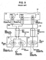
- the logical connections for signalling transfer between the Core Network 10 and the Radio Network Controller 22 are set as shown in FIG. 9 .
- FIG. 9 when the CS signalling connection 511 of the CS domain 611 and the PS signalling connection 512 of the PS domain 612 are established in the mobile terminal 51, andwhen themobile terminal 51 further attempts to receive the MBMS service in the current state, there is no need to execute another signalling connection establishment processing for the MBMS service to the mobile terminal 51.
- an MBMS signalling connection may be regarded as being included in the PS domain having the packet switching function, whereby the mobile terminal 51 is able to use the PS Iu connection 121 which is an already established logical connection.
- the SGSN 12 does not execute paging processing in conformity with an RANAP (Radio Access Network Application Part) protocol (processing for recognizing one of a plurality of Radio Network Controller areas (cells) that a mobile terminal belongs to).
- RANAP Radio Access Network Application Part
- another mobile terminal 52 in which the signalling connection of the PS domain is not established, requires a new MBMS signalling connection 523 in order to receive the MBMS service and accordingly the SGSN 12 is requested to execute the paging processing.
- Reference numeral 613 denotes a PS domain of the mobile terminal 52
- 712 denotes an RRC signalling connection of the mobile terminal 52.
- Reference numeral 212 denotes an RRC connection between the mobile terminal 52 and the Radio Network Controller 22, and 122 denotes an MBMS Iu connection between the Core Network 10 and the Radio Network Controller 22.
- PS signalling connection 512 for the PS domain is established in the mobile terminal 51 and further the logical connection of PS Iu connection 121 is established between the Core Network 10 and the Radio Network Controller 22 when the W-CDMA mobile communication system attempts to newly support the MBMS service
- MBMS signalling may be performed using this PS Iu connection 121.
- the signalling connection thus described is, however, shared with both the PS service including an existing packet switched service and such a new MBMS service, which raises the problem such that processing contention is caused between different types of services. More specifically, when an establishment request of a usual packet service (such as a receipt of packet data) is generated while the MBMS service is being provided, the paging processing is not executed because the PS signalling connection has already been established, but the signalling connection that is in use for the MBMS service works also for processing to establish an RAB (Radio Access Bearer) of the packet service. This is more likely to cause the processing contention between the MBMS service and the packet communication service.
- RAB Radio Access Bearer
- the processing in the SGSN 12 of the Core Network 10 increases in complexity. More specifically, if the mobile terminal has the established PS signalling connection for usual packet service, a massage is transmitted/received using this existing PS signalling connection because of the mobile terminal being designed to have only one signalling connection in the PS domain. Therefore, a new PS signalling connection for the MBMS service does not need to be established. However, the mobile terminal not having the established PS signalling connection needs a new PS signalling connection to receive the MBMS service by which MBMS messages may be transmitted/received. This requires the SGSN to check into PS signalling establishing statuses of each mobile terminal and to determine the signalling connection used for message transmission and reception. Besides, even when the MBMS service is terminated, the SGSN needs to determine whether the mobile terminal is still receiving the usual packet service in order to perform release processing of the signalling connection if necessary.
- an object of the preferred embodiments of the present invention to provide a mobile communication system in which an occurrence of contention between an existing packet communication service and a new MBMS service is eliminated, a method of controlling operations of the system, and a node used in the system.
- Another object of the preferred embodiments of the present invention is to provide a mobile communication system in which processing complexity in the SGSN is eliminated, a method of controlling operations of the system, and a node used in the system.
- EP 1 363 467 A2 discloses a method for setting up a signaling connection between a RNC and a SGSN in a mobile communication system.
- the method allows an existing signaling connection between the RNC and the SGSN, used for a particular MBMS service between the SGSN and an UE, to be also used by another UE requesting the same MBMS service. This reduces the time involved in creating an additional signaling connection.
- MBMS-000030 MBMS With Iu-Flex
- XP-002252458 pages 1 to 21 , discloses a scheme for setting a "default SGSN" when an UE selects a MBMS service.
- the identification of a default SGSN for each MBMS service may be stored and managed by either an RNC or a SGSN, and may be erased when the corresponding MBMS service is released.
- One aspect of the subject invention is a mobile communication system that includes a core network "CN” having a CN node with an existing packet-switching "PS" Iu connection to a radio network controller "RNC", PS communication from the CN to a mobile terminal "UE” being by means of the PS Iu connection and by means of a Radio Resource Control “RRC” Connection extending from the RNC to a PS signalling connection on the UE.
- CN core network
- RNC Radio Network Controller
- the system includes a multicast-data "MBMS" connection-setting means for establishing multicast-data communication between the CN node and the UE by: setting a MBMS Iu connection from the CN node to the RNC, the MBMS Iu connection being set so as to be separate from, and allowing higher-speed communication than, the existing PS Iu connection; and, establishing separate MBMS communication from the RNC to the UE by means of extending the RRC connection to a MBMS signalling connection separate on the UE from the PS signalling connection.
- MBMS multicast-data "MBMS" connection-setting means for establishing multicast-data communication between the CN node and the UE by: setting a MBMS Iu connection from the CN node to the RNC, the MBMS Iu connection being set so as to be separate from, and allowing higher-speed communication than, the existing PS Iu connection; and, establishing separate MBMS communication from the RNC to the UE by means of extending the RRC connection to a
- the system may include a plurality of mobile terminals, with the connection-setting means setting the connection between the core network node and the radio network controller for the multicast-data communication to be a common connection for those of the plurality of mobile terminals that attempt to receive a service of the multicast-data communication.
- Another aspect of the subject invention is a method of controlling operations in a mobile communication system that includes a core network having a CN node with an existing packet-switching "PS" Iu connection to a radio network controller "RNC", PS communication from the CN to a mobile terminal "UE” being by means of the PS Iu connection and by means of a Radio Resource Control “RRC” Connection extending from the RNC to a PS signalling connection on the UE.
- RNC Radio Resource Control
- the method includes steps of: setting a MBMS Iu connection from the CN node to the RNC, the MBMS Iu connection being set so as to be separate from, and allowing higher-speed communication than, the existing PS Iu connection; and, establishing separate MBMS communication from the RNC to the UE by means of extending the RRC connection to a MBMS signalling connection separate on the UE from the PS signalling connection.
- the system may include a plurality of mobile terminals, with the connection-setting step setting the connection between the core network node and the radio network controller for the multicast-data communication to be a common connection for those of the plurality of mobile terminals that attempt to receive a service of the multicast-data communication.
- a further aspect of the subject invention is a node in a mobile communication system including a core network "CN” having a CN node with an existing packet-switching "PS" Iu connection to a radio network controller "RNC", PS communication from the CN to a mobile terminal "UE” being by means of the PS Iu connection and by means of a Radio Resource Control “RRC” Connection extending from the RNC to a PS signalling connection on the UE.
- RRC Radio Resource Control
- the node in the mobile communication system includes a multicast-data "MBMS" connection-setting means for establishing multicast-data communication between the CN node and the UE by: setting a MBMS Iu connection from the CN node to the RNC, the MBMS Iu connection being set so as to be separate from, and allowing higher-speed communication than, the existing PS Iu connection; and, establishing separate MBMS communication from the RNC to the UE by means of extending the RRC connection to a MBMS signaling connection separate on the UE from the PS signalling connection.
- MBMS multicast-data "MBMS" connection-setting means for establishing multicast-data communication between the CN node and the UE by: setting a MBMS Iu connection from the CN node to the RNC, the MBMS Iu connection being set so as to be separate from, and allowing higher-speed communication than, the existing PS Iu connection; and, establishing separate MBMS communication from the RNC to the UE by means of extending the
- a still further aspect of the subject invention is a medium carrying a computer-readable program for making a computer execute operation-controlling of a node in a mobile communication system that includes a core network having a node with a packet-switching connection to a radio network controller for packet data communication with a mobile terminal by means of the radio network controller.
- the program is able to make the computer execute any of the methods in the method aspect of the invention described above.
- FIG. 1 is a schematic diagram showing a system configuration according to one embodiment of the present invention, where the same reference numerals are allocated to the same components as those in FIGS. 7 to 9 .
- a Core Network (CN) 10 includes an MSC 11 (defined as a CS domain) having a circuit switching function for voice communication and an SGSN (Serving GPRS (Global Packet Radio Service) Support Node) 12 (defined as a PS domain) having a packet switching function for packet data communication.
- the SGSN 12 is available for an existing packet service as well as the previously described new MBMS service (broadcast or multicast communication service supporting higher speed data communication as compared with the packet service), and mobile terminals 51 and 52 are available for the same as well.
- a Radio Network Controller (RNC) 22 manages radio resources , controls a Node B (not shown) that is a radio base station, and the like. Between the Radio Network Controller 22 and each of the mobile terminals 51 and 52, RRC connections 211 and 212 are set, respectively.
- a CS signalling connection 511 and a PS signalling connection 512 has already been established, and accordingly, as logical connections, a CS Iu connection 111 and a PS Iu connection 121 for the mobile terminal 51 are established on an Iu interface between the Core Network 10 and the Radio Network Controller 22. This enables the mobile terminal 51 to transmit/receive a massage to/from the MSC 11 and the SGSN 12.
- the PS Iu connection 121 is not used as the logical connection for the MBMS service but in place thereof, an MBMS Iu connection 122 dedicated to the MBMS service is independently established.
- the PS signalling connection 512 and an MBMS signalling connection 513 are established in a PS domain 612. This allows the mobile terminal 51 to transmit/receive massages necessary for receiving the MBMS service to/from the SGSN 12.
- the mobile terminal 52 shares the use of the MBMS Iu connection 122 which has already been established for the MBMS service intended for the mobile terminal 51.
- this MBMS Iu connection 122 is shared among these three mobile terminals.
- Reference numeral 523 shown in the mobile terminal 52 denotes the MBMS signalling connection.
- the MBMS Iu connection 122 shared with a plurality of mobile terminals handles only massages related to the MBMS service and is set as a signalling connection for each PS domain 612, 614.
- the following processings are executed. Among these are: so called “Joining” processing for notifying a network from the mobile terminal that it wishes to receive data in a multicast mode ( it wishes to receive a service in a multicast mode or to subscribe to the service), "MBMS notification” processing for notifying that the multicast data is to be transferred, transfer processing for MBMS data, "Leaving” processing for leaving the multicast service, and the like.
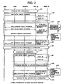
- FIG. 2 is a sequence diagram showing operations of the "Joining” processing
- FIGS. 3 and 4 are sequence diagrams showing operations of the data transfer and the "Leaving" processing. Steps described in rectangular boxes in the right ends in each drawing represent the processings executed in the SGSN 12.
- FIG. 4 is the diagram showing details of MBMS connection establishment processing (step C3) in the sequence of FIG. 3 .
- the mobile terminal 51 establishes the RRC connection with the Radio Network Controller 22 when triggered by turning-on operation of power supply and the like (step A1). Then, the mobile terminal 51 notifies the SGSN 12 of information about the "Joining". TheRadioNetworkController22 sends aconnection establishment request to the SGSN 12 to establish the Iu connection therewith. Through this processing, the SGSN 12 recognizes that there exists a reception request of MBMS data from the mobile terminal 51 (step A2).
- a massage "Initial Direct Transfer” is used to establish the signalling connection and, on radio communication it is used to transmit an initial NAS massage (which is transmitted and received between the mobile terminal and the Core Network).
- SCCP is an abbreviation for “Signalling Connection Control Part” which means a signal system for efficiently transferring application signals and information
- CR is an abbreviation for “Connection Request” which is used for a setting request of the signalling connection
- CC is an abbreviation for "Connection Confirm” which is a massage notifying that the setting of the signalling connection has been executed.
- the SGSN 12 executes authentication and security processing, and when ascertaining that the mobile terminal is an authorized terminal (steps A3, A3'), the SGSN 12 notifies an upper gateway (GGSN) which is not shown, of the "Joining" information of the mobile terminal 51, and also notifies the mobile terminal 51 that the "Joining" processing has been completed (steps A4, A5). Upon the completion of the "Joining" processing, the SGSN 12 releases once the Iu connection because the connection is not necessary until the transmission of MBMS data (step A6).
- GGSN upper gateway
- step A3 represents "Data Form 1" which is a massage used to transmit various SCCP data (information about requests or responses for authentication, and the like) to an opposite node.
- the SGSN 12 executes, for the mobile terminal 52, the same processing as for the mobile terminal 51 (steps A8, A9 ) , and when ascertaining that the mobile terminal 52 is an authorized terminal, the SGSN 12 notifies the gateway GGSN of the "Joining" information of the mobile terminal 52 and also reports the completion of the "Joining" processing to the mobile terminal 52 (steps A10, A11). Upon the completion of the "Joining processing", the SGSN 12 releases once the Iu connection (step A12). This interim connection release is performed because "MBMS notification" processing shown in FIG. 3 is not always executed immediately after the "Joining" processing and the SGSN 12 therefore efficiently assigns resources to users who receive other services until the execution of the "MBMS notification" processing.
- the "MBMS notification” processing is executed to notify the MBMS service subscribing mobile terminals 51 and 52 that the MBMS data is to be transferred (steps C1, C2).
- a request massage from the SGSN 12 to the Radio Network Controller 22 to transmit the "MBMS notification" to the mobile terminals is sent in a connectionless manner because the Iu connection is being released at the "Joining" processing.
- This request massage to the Radio Network Controller 22 comprises only one massage, but to the mobile terminals receiving the same MBMS service, such a request massage may be transmitted simultaneously to a plurality of mobile terminals by using a group number indicative of a group receiving the same MBMS service.
- "UDT” is an abbreviation for "Unitdata” which is a massage used to transmit data in a connectionless manner.
- This group number is an identification number indicating each type of the MBMS service.
- Such identification numbers and the corresponding service types are pre-informed to many and unspecified mobile terminals from a system (a server providing the MBMS service), whereby the mobile terminal transmits to the SGSN 12 the identification number corresponding to the desired service type by containing it in the "Joining" information.
- This allows the SGSN 12 to recognize, based on the identification number included in the "Joining" information, which type of the MBMS service to provide for the mobile terminal which has transmitted the "Joining" request.
- the mobile terminal 51 which has received the "MBMS notification" establishes the RRC connection again with the Radio Network Controller 22 for the reception of the MBMS service (step B1), and then in order to request the MBMS service, the Radio Network Controller 22 notifies the SGSN 12 in a connectionless manner that the massage has been received by the mobile terminal 51 (step B2).
- the Radio Network Controller 22 requests of the Radio Network Controller 22 to establish the Iu connection 122 (steps B3, B3').
- This processing eliminates the need of establishing the Iu connection for each call to the MBMS service, thereby efficiently reducing an amount of massages.
- the SGSN 12 executes authentication and security processing, and when ascertaining that the mobile terminal 51 is an authorized terminal, theSGSN12 notifies the mobile terminal 51 of the completion of the MBMS service request (steps B4, B5).
- the Iu connection establishment request is not transmitted to the Radio Network Controller 22 because the MBMS Iu connectionhas alreadybeen established (steps B7, B8).
- the SGSN 12 executes authentication and security processing for the mobile terminal 52 in the same manner as for the mobile terminal 51, and when ascertaining that the mobile terminal 52 is an authorized terminal, the SGSN 12 notifies the mobile terminal 52 that the MBMS service request has been completed (steps B9, B10).
- MBMS RAB establishment processing Since the Iu connection 122 is shared in the MBMS service, MBMS RAB establishment processing, MBMS data transfer, and MBMS RAB release processing to be performed after the data transfer, are executed using the same connection (steps C4, C4', C5, C6 and C6').
- Step C7 when the MBMS data reception is no longer necessary, the "Leaving" processing is executed to leave the MBMS service (Step C7).
- Step C8 when the "Leaving" processing is completed only in the mobile terminal 52, there is no need to execute the release processing of the Iu connection 122 because the mobile terminal 51 has not performed the “Leaving” processing (Step C8).
- the SGSN 12 releases the Iu connection 122 with the Radio Network Controller 22 to terminate the MBMS multicast service (Steps C9, C9').
- step C9 "RLSD” represents “Released” which is used to release the signalling connection and assigned resources, and “RLC” represents “Release Complete” which is used to notify the completion of the release.
- the Iu connection 122 dedicated to the MBMS service is provided separately and independently from the PS Iu connection 121, so that an occurrence of contention between the MBMS service and other services (packet data communication) is eliminated, thus allowing the provision of the MBMS service without being conscious of other services, and particularly eliminating the need for checking into the signalling connection establishment status of other services.
- the MBMS signalling connection is so designed that it is shared with a plurality of mobile terminals subscribing to the MBMS service, which enables transmission of a massage using the group number (TMGI: Temporary mobile Group Identify) indicative of being a subscriber of the MBMS service without the need for transmitting the massage individually to the mobile terminals using their respective identification numbers (IMSI: International Mobile Subscriber Identify). Furthermore, once the Iu connection 122 is established, there is no need to release it until all mobile terminals receiving the same MBMS service make "Leaving", thereby resulting in the reduced amount of massages transmitted between nodes.
- TMGI Temporary mobile Group Identify
- FIG. 5 is a schematic block diagram according to another embodiment of the present invention wherein the same reference numerals are allocated to the same components as those in FIG. 1 .
- This embodiment differs from the embodiment shown in FIG. 1 in that among the three signalling connections established in the mobile terminal 51, the MBMS signalling connection 513 is established not in the PS domain 612 but in a newly provided MBMS domain 613.
- the Core Network 10 manages different areas depending on domains in such a manner as to manage mobile terminal locations in the area called LA (Local Area) for the CS domain and to manage mobile terminal locations in the area called RA (Routing Area) for the PS domain .
- LA Local Area
- RA Remote Area
- destination addresses of the MBMS information are managed in an area called an MBMS area which is not necessarily the same as the RA area of the PS domain.
- two areas need to be checked in one domain because location registration is required in response to an change in the MBMS area even when the RA as the PS domain remains the same.
- the domain is divided into the PS domain 612 and an MBMS domain 613 as shown in FIG. 5 to thereby bring the domain and the management area thereof into a one-to-one correspondence, thus facilitating the management.
- Radio Network Controller 22 needs to perform the releasing processing of the RRC signalling connection.
- This embodiment requires the transmission of an "RRC: Signalling Connection Release" message to each domain, however, the previous embodiment requires such transmission only once since the domains are not divided.
- FIG. 6 is a schematic block diagram according to still another embodiment of the present invention, wherein the same reference numerals are allocated to the same components as those in FIG. 1 .
- the configuration is identical to that in the FIG. 1 except that the MBMS Iu connections 122 and 123 for the MBMS signaling connections are provided so as to correspond to each mobile terminal.
- the establishment processing and release processingof these Iu connections 122 and 123 are executed by the SGSN 12 independently to each mobile terminal, while the MBMS signalling connection is provided separately from the PS Iu connection 121 for the PS signalling connection, therefore an occurrence of contention with different services and the processing complexity in the SGSN may be eliminated.
- the same massage needs to be transmitted to a plurality of specified mobile terminals, which raises the possibility to cause congestion induced by a plurality of massages transmitted on radio communication and to adversely affect the processing capability due to the increased amount of the massages to be processed between the nodes.
- the Iu connection is established which is common to a plurality of mobile terminals, thereby eliminating an occurrence of congestion induced by the large amount of massages transmitted on radio communication and also eliminating adverse effects to the processing capability between the nodes.
- the operation in the above described embodiments may be programmed as operation procedures and stored in a recording medium capable of being read by a computer (CPU), and that the computer reads the recording medium and sequentially executes the operation procedures to thereby realize the operation.
- a computer CPU
- the Iu connection for the MBMS service is provided separately from the PS Iu connection, so that the occurrence of contention between the MBMS service and other services (Packet data service) is eliminated, thereby allowing the provision of the MBMS service without being conscious of other services, and particularly providing an effect that it is no longer necessary to check into establishment statuses of signalling connections of other services.
- Packet data service Packet data service
- a connection necessary to provide a service supporting high-speed data communication referred to as an MBMS is configured on an Iu interface
- contention with the other packet communication service is eliminated.
- a PS (packet switching processing) functional connection for an existing packet communication service and a connection for a new MBMS service offering high-speed data communication are provided separately and independently from each other. This eliminates the contention between different types of services of the PS service and the MBMS service to thereby enable executing processing of such different types of services without being conscious of mutual processing.
- release processing of the connection may be executed independently to each service, thereby eliminating processing complexity in the SGSN.
Description
- The present invention relates to a mobile communication system, a method of controlling operation thereof and a node used in the system, and more particularly, to a configuration system of a signalling connection on an interface between a Core Network and a Radio Network Controller (RNC), the signalling connection being necessary when providing a broadcast or multicast service supporting high-speed data communication called MBMS (Multimedia Broadcast Multicast Service) in the mobile communication system.
- Techniques of configuring a signalling connection operable for transfer control of various control signals in a W-CDMA (Wideband-CDMA) mobile communication system are defined in "RRC Services provided to upper layers" in Chap. 5 of the specification TS 25.331 (Non-Patent Document 1) prepared by the 3GPP (Third Generation Partnership Project). By referring to
FIG. 7 , the signalling connection configuring techniques will be described. - It will be observed from
FIG. 7 that the W-CDMA mobile communication system comprises a Core Network (CN) 10 including a switching network, a Radio Network Controller (RNC) 22, and a mobile terminal (UE) 51. Between the Core Network 10 and the Radio Network Controller 22,logical connections logical connection 111 is referred to as a CS Iu connection which is established between an MSC (Mobile-services Switching Center) 11 configuring the Core Network 10 and the Radio Network Controller 22, and is functional for a CS domain corresponding to a CS network having a circuit switching function for voice communication. - The
logical connection 121 is referred to as a PS Iu connection which is established between an SGSN ( Serving GPRS ( Global Packet Radio Service) Support Node) 12 configuring the Core Network 10 and the Radio NetworkController 22, and is functional for a PS domain corresponding to a PS network having a packet switching function. The Radio Network Controller 22 manages radio resources, controls a Node B (radio base station) which is not shown, and the like, and is typified by a handover controlling device. - Established between the Radio Network Controller 22 and the
mobile terminal 51 is an RRC (Radio Resource Connection)connection 211 for signalling transfer. TheRRC connection 211 corresponds to anRRC signalling connection 711 in themobile terminal 51. ThisRRC signalling connection 711 is configured with aCS signalling connection 511 for aCS domain 611 and aPS signalling connection 512 for aPS domain 612. - Thus, the W-CDMA mobile communication system makes it possible to establish in the
mobile terminal 51 thesignalling connections CS domain 611 and thePS domain 612, respectively, which is def ined in theNon-Patent Document 1. - The W-CDMA mobile communication system having such a configuration may sometimes support a new service such as MBMS (Multimedia Broadcast Multicast Service). More specifically, when a broadcast or multicast service called MBMS supporting high speed, large capacity data communication of moving images or images with sound information is provided, the W-CDMA mobile communication system takes a configuration shown in
FIG. 8. FIG. 8 represents the case where the multicast service is provided. - In
FIG. 8 , the same reference numerals are allocated to the same components as those inFIG. 7 . Referring toFIG. 8 , there is shown a RAN (Radio Access Network) 21 provided between the Core Network 10 and themobile terminals 51 to 53, which comprises the Radio Network Controller (RNC) 22 and aNode B 23. Note here that inFIG. 7 only the Radio Network Controller 22 is shown while theNode B 23 is omitted. - Within an MBMS
coverage 41 where MBMS multicast service information is distributed, MBMS service subscribingmobile terminals mobile terminal 53 are being present. Multicast is a service for distributing the same data to multiple specified destination addresses (mobile terminals). - In this case, the logical connections for signalling transfer between the Core Network 10 and the Radio Network Controller 22 are set as shown in
FIG. 9 . As seen fromFIG. 9 , when theCS signalling connection 511 of theCS domain 611 and thePS signalling connection 512 of thePS domain 612 are established in themobile terminal 51, andwhen themobileterminal 51 further attempts to receive the MBMS service in the current state, there is no need to execute another signalling connection establishment processing for the MBMS service to themobile terminal 51. More specifically, since the MBMS service is provided in packet communication, an MBMS signalling connection may be regarded as being included in the PS domain having the packet switching function, whereby themobile terminal 51 is able to use thePS Iu connection 121 which is an already established logical connection. - Thus, when the Iu connection for the PS domain has been established in the mobile terminal, the SGSN 12 does not execute paging processing in conformity with an RANAP (Radio Access Network Application Part) protocol (processing for recognizing one of a plurality of Radio Network Controller areas (cells) that a mobile terminal belongs to).
- To the contrary, another
mobile terminal 52, in which the signalling connection of the PS domain is not established, requires a newMBMS signalling connection 523 in order to receive the MBMS service and accordingly the SGSN 12 is requested to execute the paging processing.Reference numeral 613 denotes a PS domain of themobile terminal mobile terminal 52.Reference numeral 212 denotes an RRC connection between themobile terminal 52 and the Radio Network Controller 22, and 122 denotes an MBMS Iu connection between the Core Network 10 and the Radio Network Controller 22. - As described by referring
FIG. 9 , if thePS signalling connection 512 for the PS domain is established in themobile terminal 51 and further the logical connection ofPS Iu connection 121 is established between the Core Network 10 and the Radio NetworkController 22 when the W-CDMA mobile communication system attempts to newly support the MBMS service, MBMS signalling may be performed using thisPS Iu connection 121. - The signalling connection thus described is, however, shared with both the PS service including an existing packet switched service and such a new MBMS service, which raises the problem such that processing contention is caused between different types of services. More specifically, when an establishment request of a usual packet service (such as a receipt of packet data) is generated while the MBMS service is being provided, the paging processing is not executed because the PS signalling connection has already been established, but the signalling connection that is in use for the MBMS service works also for processing to establish an RAB (Radio Access Bearer) of the packet service. This is more likely to cause the processing contention between the MBMS service and the packet communication service.
- Also, another problem may arise in that the processing in the
SGSN 12 of the Core Network 10 increases in complexity. More specifically, if the mobile terminal has the established PS signalling connection for usual packet service, a massage is transmitted/received using this existing PS signalling connection because of the mobile terminal being designed to have only one signalling connection in the PS domain. Therefore, a new PS signalling connection for the MBMS service does not need to be established. However, the mobile terminal not having the established PS signalling connection needs a new PS signalling connection to receive the MBMS service by which MBMS messages may be transmitted/received. This requires the SGSN to check into PS signalling establishing statuses of each mobile terminal and to determine the signalling connection used for message transmission and reception. Besides, even when the MBMS service is terminated, the SGSN needs to determine whether the mobile terminal is still receiving the usual packet service in order to perform release processing of the signalling connection if necessary. - It is, therefore, an object of the preferred embodiments of the present invention to provide a mobile communication system in which an occurrence of contention between an existing packet communication service and a new MBMS service is eliminated, a method of controlling operations of the system, and a node used in the system.
- Another object of the preferred embodiments of the present invention is to provide a mobile communication system in which processing complexity in the SGSN is eliminated, a method of controlling operations of the system, and a node used in the system.
-
EP 1 363 467 A2 (Samsung - "MBMS-000030: MBMS With Iu-Flex", Samsung, (06-05-2002), XP-002252458, , discloses a scheme for setting a "default SGSN" when an UE selects a MBMS service. The identification of a default SGSN for each MBMS service may be stored and managed by either an RNC or a SGSN, and may be erased when the corresponding MBMS service is released.
- 3GPP TSG-RAN WG2 Meeting #32, R2-022699 (23-09-2002), Adhoc on MBMS RNC signalling flows; "Proposed update to R2- 022601", XP-002264483, , discloses that one solution to signalling connection for MBMS multicast service involves categorizing Iu signalling connections to one 'Parent Iu' and many 'Linked Iu's. In this solution, all UEs have their own Iu signalling connection, even if receiving the same MBMS service. Only the Parent Iu connection is managed by the SGSN and RNC, with the Linked Ius not being used. Two other solutions are described in this reference.
- One aspect of the subject invention is a mobile communication system that includes a core network "CN" having a CN node with an existing packet-switching "PS" Iu connection to a radio network controller "RNC", PS communication from the CN to a mobile terminal "UE" being by means of the PS Iu connection and by means of a Radio Resource Control "RRC" Connection extending from the RNC to a PS signalling connection on the UE. The system includes a multicast-data "MBMS" connection-setting means for establishing multicast-data communication between the CN node and the UE by: setting a MBMS Iu connection from the CN node to the RNC, the MBMS Iu connection being set so as to be separate from, and allowing higher-speed communication than, the existing PS Iu connection; and, establishing separate MBMS communication from the RNC to the UE by means of extending the RRC connection to a MBMS signalling connection separate on the UE from the PS signalling connection.
- The system may include a plurality of mobile terminals, with the connection-setting means setting the connection between the core network node and the radio network controller for the multicast-data communication to be a common connection for those of the plurality of mobile terminals that attempt to receive a service of the multicast-data communication.
- Another aspect of the subject invention is a method of controlling operations in a mobile communication system that includes a core network having a CN node with an existing packet-switching "PS" Iu connection to a radio network controller "RNC", PS communication from the CN to a mobile terminal "UE" being by means of the PS Iu connection and by means of a Radio Resource Control "RRC" Connection extending from the RNC to a PS signalling connection on the UE. The method includes steps of: setting a MBMS Iu connection from the CN node to the RNC, the MBMS Iu connection being set so as to be separate from, and allowing higher-speed communication than, the existing PS Iu connection; and, establishing separate MBMS communication from the RNC to the UE by means of extending the RRC connection to a MBMS signalling connection separate on the UE from the PS signalling connection.
- The system may include a plurality of mobile terminals, with the connection-setting step setting the connection between the core network node and the radio network controller for the multicast-data communication to be a common connection for those of the plurality of mobile terminals that attempt to receive a service of the multicast-data communication.
- A further aspect of the subject invention is a node in a mobile communication system including a core network "CN" having a CN node with an existing packet-switching "PS" Iu connection to a radio network controller "RNC", PS communication from the CN to a mobile terminal "UE" being by means of the PS Iu connection and by means of a Radio Resource Control "RRC" Connection extending from the RNC to a PS signalling connection on the UE. The node in the mobile communication system includes a multicast-data "MBMS" connection-setting means for establishing multicast-data communication between the CN node and the UE by: setting a MBMS Iu connection from the CN node to the RNC, the MBMS Iu connection being set so as to be separate from, and allowing higher-speed communication than, the existing PS Iu connection; and, establishing separate MBMS communication from the RNC to the UE by means of extending the RRC connection to a MBMS signaling connection separate on the UE from the PS signalling connection.
- A still further aspect of the subject invention is a medium carrying a computer-readable program for making a computer execute operation-controlling of a node in a mobile communication system that includes a core network having a node with a packet-switching connection to a radio network controller for packet data communication with a mobile terminal by means of the radio network controller. The program is able to make the computer execute any of the methods in the method aspect of the invention described above.
- Preferred features of the present invention will now be described, by way of example only, with reference to the accompanying drawings, in which:-
-
FIG. 1 is a schematic block diagram according to one embodiment of the present invention; -
FIG. 2 is a sequence diagram partly showing processing for "Joining" in a MBSM multicast service according to the one embodiment of the present invention; -
FIG. 3 is a sequence diagram showing data transfer and the processing for "Joining" in the MBSM multicast service according to the one embodiment of the present invention; -
FIG. 4 is a sequence diagram showing detailed processing for a step C3 shown inFIG. 3 ; -
FIG. 5 is a schematic block diagram according to another embodiment of the present invention; -
FIG. 6 is a schematic block diagram according to still another embodiment of the present invention; -
FIG. 7 is a schematic block diagram illustrating a conventional example; -
FIG. 8 is a schematic system diagram for the MBSM multicast service; and, -
FIG 9 is a diagram illustrating the case of receiving the MBSM multicast service in the configuration shown inFIG. 7 . - Embodiments of thepresent invention will be described below with reference to the accompanied drawings.
FIG. 1 is a schematic diagram showing a system configuration according to one embodiment of the present invention, where the same reference numerals are allocated to the same components as those inFIGS. 7 to 9 . It will be observed fromFIG. 1 that a Core Network (CN) 10 includes an MSC 11 (defined as a CS domain) having a circuit switching function for voice communication and an SGSN (Serving GPRS (Global Packet Radio Service) Support Node) 12 (defined as a PS domain) having a packet switching function for packet data communication. TheSGSN 12 is available for an existing packet service as well as the previously described new MBMS service (broadcast or multicast communication service supporting higher speed data communication as compared with the packet service), andmobile terminals - These
mobile terminals FIG. 8 ), and are now subscribing to the MBMS service. - A Radio Network Controller (RNC) 22 manages radio resources , controls a Node B (not shown) that is a radio base station, and the like. Between the
Radio Network Controller 22 and each of themobile terminals RRC connections mobile terminal 51, aCS signalling connection 511 and aPS signalling connection 512 has already been established, and accordingly, as logical connections, aCS Iu connection 111 and aPS Iu connection 121 for themobile terminal 51 are established on an Iu interface between theCore Network 10 and theRadio Network Controller 22. This enables themobile terminal 51 to transmit/receive a massage to/from theMSC 11 and theSGSN 12. - Furthermore in this embodiment, when the mobile terminal 51 attempts to receive the MBMS service, the
PS Iu connection 121 is not used as the logical connection for the MBMS service but in place thereof, anMBMS Iu connection 122 dedicated to the MBMS service is independently established. On themobile terminal 51 side, thePS signalling connection 512 and anMBMS signalling connection 513 are established in aPS domain 612. This allows themobile terminal 51 to transmit/receive massages necessary for receiving the MBMS service to/from theSGSN 12. - At this time, if the other mobile terminal 52 attempts to receive the same MBMS service, the mobile terminal 52 shares the use of the
MBMS Iu connection 122 which has already been established for the MBMS service intended for themobile terminal 51. When still another mobile terminal attempts to receive the same MBMS service, thisMBMS Iu connection 122 is shared among these three mobile terminals.Reference numeral 523 shown in themobile terminal 52 denotes the MBMS signalling connection. - The
MBMS Iu connection 122 shared with a plurality of mobile terminals handles only massages related to the MBMS service and is set as a signalling connection for eachPS domain - In the MBMS multicast service, the following processings are executed. Among these are: so called "Joining" processing for notifying a network from the mobile terminal that it wishes to receive data in a multicast mode ( it wishes to receive a service in a multicast mode or to subscribe to the service), "MBMS notification" processing for notifying that the multicast data is to be transferred, transfer processing for MBMS data, "Leaving" processing for leaving the multicast service, and the like.
- Next, the entire operation in this embodiment will be described in further detail with reference to the sequence diagrams of
FIGS. 2 to 4 . In this embodiment, the "Joining" processing forthemobile terminal 51 is completed, and thereafter a "Joining" request from the other mobile terminal 52 is notified.FIG. 2 is a sequence diagram showing operations of the "Joining" processing, andFIGS. 3 and4 are sequence diagrams showing operations of the data transfer and the "Leaving" processing. Steps described in rectangular boxes in the right ends in each drawing represent the processings executed in theSGSN 12.FIG. 4 is the diagram showing details of MBMS connection establishment processing (step C3) in the sequence ofFIG. 3 . - First, the
mobile terminal 51 establishes the RRC connection with theRadio Network Controller 22 when triggered by turning-on operation of power supply and the like (step A1). Then, themobile terminal 51 notifies theSGSN 12 of information about the "Joining". TheRadioNetworkController22 sends aconnection establishment request to theSGSN 12 to establish the Iu connection therewith. Through this processing, theSGSN 12 recognizes that there exists a reception request of MBMS data from the mobile terminal 51 (step A2). - In step A2, a massage "Initial Direct Transfer" is used to establish the signalling connection and, on radio communication it is used to transmit an initial NAS massage (which is transmitted and received between the mobile terminal and the Core Network). In addition, "SCCP" is an abbreviation for "Signalling Connection Control Part" which means a signal system for efficiently transferring application signals and information, "CR" is an abbreviation for "Connection Request" which is used for a setting request of the signalling connection, and "CC" is an abbreviation for "Connection Confirm" which is a massage notifying that the setting of the signalling connection has been executed.
- Subsequently, the
SGSN 12 executes authentication and security processing, and when ascertaining that the mobile terminal is an authorized terminal (steps A3, A3'), theSGSN 12 notifies an upper gateway (GGSN) which is not shown, of the "Joining" information of themobile terminal 51, and also notifies themobile terminal 51 that the "Joining" processing has been completed (steps A4, A5). Upon the completion of the "Joining" processing, theSGSN 12 releases once the Iu connection because the connection is not necessary until the transmission of MBMS data (step A6). - In step A3, "DT1" represents "
Data Form 1" which is a massage used to transmit various SCCP data (information about requests or responses for authentication, and the like) to an opposite node. - At this time, when the information of "Joining" is notified to the
SGSN 12 from themobile terminal 52 which has the established RRC connection since the power was turned on (step A7), theSGSN 12 executes, for themobile terminal 52, the same processing as for the mobile terminal 51 (steps A8, A9 ) , and when ascertaining that themobile terminal 52 is an authorized terminal, theSGSN 12 notifies the gateway GGSN of the "Joining" information of themobile terminal 52 and also reports the completion of the "Joining" processing to the mobile terminal 52 (steps A10, A11). Upon the completion of the "Joining processing", theSGSN 12 releases once the Iu connection (step A12). This interim connection release is performed because "MBMS notification" processing shown inFIG. 3 is not always executed immediately after the "Joining" processing and theSGSN 12 therefore efficiently assigns resources to users who receive other services until the execution of the "MBMS notification" processing. - After the completion of the "Joining" processing executed for each mobile terminal, the "MBMS notification" processing is executed to notify the MBMS service subscribing
mobile terminals SGSN 12 to theRadio Network Controller 22 to transmit the "MBMS notification" to the mobile terminals is sent in a connectionless manner because the Iu connection is being released at the "Joining" processing. This request massage to theRadio Network Controller 22 comprises only one massage, but to the mobile terminals receiving the same MBMS service, such a request massage may be transmitted simultaneously to a plurality of mobile terminals by using a group number indicative of a group receiving the same MBMS service. Note here that "UDT" is an abbreviation for "Unitdata" which is a massage used to transmit data in a connectionless manner. - This group number is an identification number indicating each type of the MBMS service. Such identification numbers and the corresponding service types are pre-informed to many and unspecified mobile terminals from a system (a server providing the MBMS service), whereby the mobile terminal transmits to the
SGSN 12 the identification number corresponding to the desired service type by containing it in the "Joining" information. This allows theSGSN 12 to recognize, based on the identification number included in the "Joining" information, which type of the MBMS service to provide for the mobile terminal which has transmitted the "Joining" request. - The
mobile terminal 51 which has received the "MBMS notification" establishes the RRC connection again with theRadio Network Controller 22 for the reception of the MBMS service (step B1), and then in order to request the MBMS service, theRadio Network Controller 22 notifies theSGSN 12 in a connectionless manner that the massage has been received by the mobile terminal 51 (step B2). Next, when the MBMS service request from themobile terminal 51 is the first one out of a plurality of mobile terminals being present in the same MBMS area 41 (seeFIG. 8 ), theSGSN 12 requests of theRadio Network Controller 22 to establish the Iu connection 122 (steps B3, B3'). This processing eliminates the need of establishing the Iu connection for each call to the MBMS service, thereby efficiently reducing an amount of massages. After this, theSGSN 12 executes authentication and security processing, and when ascertaining that themobile terminal 51 is an authorized terminal, theSGSN12 notifies themobile terminal 51 of the completion of the MBMS service request (steps B4, B5). - At this time, when the information of the MBMS service request is notified to the
SGSN 12 also from themobile terminal 52 which has the established RRC connection (step B6) after the reception of the "MBMS notification", the Iu connection establishment request is not transmitted to theRadio Network Controller 22 because the MBMS Iu connectionhas alreadybeen established (steps B7, B8). TheSGSN 12 executes authentication and security processing for themobile terminal 52 in the same manner as for themobile terminal 51, and when ascertaining that themobile terminal 52 is an authorized terminal, theSGSN 12 notifies themobile terminal 52 that the MBMS service request has been completed (steps B9, B10). - Since the
Iu connection 122 is shared in the MBMS service, MBMS RAB establishment processing, MBMS data transfer, and MBMS RAB release processing to be performed after the data transfer, are executed using the same connection (steps C4, C4', C5, C6 and C6'). - Next, when the MBMS data reception is no longer necessary, the "Leaving" processing is executed to leave the MBMS service (Step C7). In this processing, even when the "Leaving" processing is completed only in the
mobile terminal 52, there is no need to execute the release processing of theIu connection 122 because themobile terminal 51 has not performed the "Leaving" processing (Step C8). When the "Leaving" processing is completed to all mobile terminals (mobile terminals 51 and 52) receiving the MBMS service in the end, theSGSN 12 releases theIu connection 122 with theRadio Network Controller 22 to terminate the MBMS multicast service (Steps C9, C9'). - In step C9, "RLSD" represents "Released" which is used to release the signalling connection and assigned resources, and "RLC" represents "Release Complete" which is used to notify the completion of the release.
- Thus, the
Iu connection 122 dedicated to the MBMS service is provided separately and independently from thePS Iu connection 121, so that an occurrence of contention between the MBMS service and other services (packet data communication) is eliminated, thus allowing the provision of the MBMS service without being conscious of other services, and particularly eliminating the need for checking into the signalling connection establishment status of other services. - Furthermore, the MBMS signalling connection is so designed that it is shared with a plurality of mobile terminals subscribing to the MBMS service, which enables transmission of a massage using the group number (TMGI: Temporary mobile Group Identify) indicative of being a subscriber of the MBMS service without the need for transmitting the massage individually to the mobile terminals using their respective identification numbers (IMSI: International Mobile Subscriber Identify). Furthermore, once the
Iu connection 122 is established, there is no need to release it until all mobile terminals receiving the same MBMS service make "Leaving", thereby resulting in the reduced amount of massages transmitted between nodes. -
FIG. 5 is a schematic block diagram according to another embodiment of the present invention wherein the same reference numerals are allocated to the same components as those inFIG. 1 . This embodiment differs from the embodiment shown inFIG. 1 in that among the three signalling connections established in themobile terminal 51, theMBMS signalling connection 513 is established not in thePS domain 612 but in a newly providedMBMS domain 613. - This means that the difference resides only in the designation of domains in the mobile terminal that is performed when a massage is sent from the
Core Network 10 to theRadio Network Controller 22 upon the establishment of the RRC connection between theRadio Network Controller 22 and the mobile terminal, and other operations are the same as the operation sequences shown inFIGS. 2 to 4 . In this embodiment, the signalling connections are established in respectively different domains, so that the management of the signalling connections in the mobile terminal is facilitated. - More specifically, the
Core Network 10 manages different areas depending on domains in such a manner as to manage mobile terminal locations in the area called LA (Local Area) for the CS domain and to manage mobile terminal locations in the area called RA (Routing Area) for the PS domain . With the MBMS service , destination addresses of the MBMS information are managed in an area called an MBMS area which is not necessarily the same as the RA area of the PS domain. For example, when the existing PS signalling connection and the new MBMS signalling connection are managed in the same PS domain, as shown inFIG. 1 , two areas need to be checked in one domain because location registration is required in response to an change in the MBMS area even when the RA as the PS domain remains the same. - To overcome this situation, the domain is divided into the
PS domain 612 and anMBMS domain 613 as shown inFIG. 5 to thereby bring the domain and the management area thereof into a one-to-one correspondence, thus facilitating the management. - When some sort of failure occurs in the
SGSN 12 , theRadio Network Controller 22 needs to perform the releasing processing of the RRC signalling connection. This embodiment requires the transmission of an "RRC: Signalling Connection Release" message to each domain, however, the previous embodiment requires such transmission only once since the domains are not divided. -
FIG. 6 is a schematic block diagram according to still another embodiment of the present invention, wherein the same reference numerals are allocated to the same components as those inFIG. 1 . In this embodiment, the configuration is identical to that in theFIG. 1 except that theMBMS Iu connections Iu connections SGSN 12 independently to each mobile terminal, while the MBMS signalling connection is provided separately from thePS Iu connection 121 for the PS signalling connection, therefore an occurrence of contention with different services and the processing complexity in the SGSN may be eliminated. - In this embodiment shown in
FIG. 6 , since different Iu connections are established to each mobile terminal, the same massage needs to be transmitted to a plurality of specified mobile terminals, which raises the possibility to cause congestion induced by a plurality of massages transmitted on radio communication and to adversely affect the processing capability due to the increased amount of the massages to be processed between the nodes. In the embodiment shown inFIG. 1 , however, the Iu connection is established which is common to a plurality of mobile terminals, thereby eliminating an occurrence of congestion induced by the large amount of massages transmitted on radio communication and also eliminating adverse effects to the processing capability between the nodes. - Note here that it is obvious that the embodiment shown in
FIG. 5 is applicable to that shown inFIG. 6 . - It is of course understood that the operation in the above described embodiments may be programmed as operation procedures and stored in a recording medium capable of being read by a computer (CPU), and that the computer reads the recording medium and sequentially executes the operation procedures to thereby realize the operation.
- As described above, according to the present invention, the Iu connection for the MBMS service is provided separately from the PS Iu connection, so that the occurrence of contention between the MBMS service and other services (Packet data service) is eliminated, thereby allowing the provision of the MBMS service without being conscious of other services, and particularly providing an effect that it is no longer necessary to check into establishment statuses of signalling connections of other services.
- While a preferred embodiment of the present invention has been described, it is to be understood that the words which have been used are words of description rather than limitation, and that changes may be made to the invention without departing from its scope as defined by the appended claims.
- Each feature disclosed in this specification (which term includes the claims) and/or shown in the drawings may be incorporated in the invention independently of other disclosed and/or illustrated features.
- The text of the abstract filed herewith is repeated here as part of the specification.
- In a mobile communication system, when a connection necessary to provide a service supporting high-speed data communication referred to as an MBMS is configured on an Iu interface, contention with the other packet communication service is eliminated. As a logical connection established between a SGSN and a Radio Network Controller in a Core Network, a PS (packet switching processing) functional connection for an existing packet communication service and a connection for a new MBMS service offering high-speed data communication are provided separately and independently from each other. This eliminates the contention between different types of services of the PS service and the MBMS service to thereby enable executing processing of such different types of services without being conscious of mutual processing. In addition, release processing of the connection may be executed independently to each service, thereby eliminating processing complexity in the SGSN.
Claims (21)
- A mobile communication system including a core network "CN" (10) having a CN node with an existing packet-switching "PS" Iu connection (121) to a radio network controller "RNC" (22), PS communication from the CN to a mobile terminal "UE" (51) being by means of the PS Iu connection and by means of a Radio Resource Control "RRC" Connection (211) extending from the RNC to a PS signalling connection (512) on the UE, the system being characterized by comprising:a multicast-data "MBMS" connection-setting means for establishing multicast-data communication between the CN node and the UE by:setting a MBMS Iu connection (122) from the CN node to the RNC, the MBMS Iu connection being set so as to be separate from, and allowing higher-speed communication than, the existing PS Iu connection (121); and,establishing separate MBMS communication from the RNC to the UE by means of extending the RRC connection (211) to a MBMS signalling connection (513) separate on the UE from the PS signalling connection (512).
- The mobile communication system according to claim 1, wherein the system comprises a plurality of UEs, and wherein the connection-setting means sets the connection between the CN node and the RNC for the multicast-data communication to be a common connection for those of the plurality of UEs that attempt to receive a service of the multicast-data communication.
- The mobile communication system according to claim 2, wherein the connection-setting means sets the connection for the multicast-data communication in response to a service-receiving request from a first UE attempting to receive the multicast-data communication service.
- The mobile communication system according to claim 2, further comprising:a connection-releasing means for releasing the connection for the multicast-data communication in response to a service-leaving request from a last UE receiving the multicast-data communication service.
- The mobile communication system according to claim 1, wherein the system comprises a plurality of UEs, and wherein the connection-setting means sets the connection between the CN node and the RNC for the multicast-data communication to be an individual connection between the CN node and the RNC for each of the plurality of UEs that attempt to receive a service of the multicast-data communication.
- The mobile communication system according to claim 5, further comprising:a connection-releasing means for, in response to a multicast-data communication service-leaving request from each of the plurality of UEs, releasing the respective individual connections.
- The mobile communication system according to claim 1, wherein the multicast-data communication is managed in a packet-switching (PS) domain that includes an area for the packet data communication with the CN node.
- The mobile communication system according to claim 1, wherein the multicast-data communication is managed in a domain which is different from a packet-switching (PS) domain for the packet data communication with the CN node.
- A method of controlling operations in a mobile communication system including a core network "CN" (10) having a CN node with an existing packet-switching "PS" Iu connection (121) to a radio network controller "RNC" (22), PS communication from the CN to a mobile terminal "UE" (51) being by means of the PS Iu connection and by means of a Radio Resource Control "RRC" Connection (211) extending from the RNC to a PS signalling connection (512) on the UE, the method being characterized by comprising steps of:setting a MBMS Iu connection (122) from the CN node to the RNC, the MBMS Iu connection being set so as to be separate from, and allowing higher-speed communication than, the existing PS Iu connection (121); and,establishing separate MBMS communication from the RNC to the UE by means of extending the RRC connection (211) to a MBMS signalling connection (513) separate on the UE from the PS signalling connection (512).
- The method according to claim 9, wherein the system comprises a plurality of UEs, and wherein the connection-setting step sets the connection between the CN node and the RNC for the multicast-data communication to be a common connection for those of the plurality of UEs that attempt to receive a service of the multicast-data communication.
- The method according to claim 10, wherein the connection-setting step sets the connection for the multicast-data communication in response to a service-receiving request from a first UE attempting to receive the multicast-data communication service.
- The method according to claim 10, further comprising the step of:a connection-releasing step of releasing the connection for the multicast-data communication in response to a service-leaving request from a last UE receiving the multicast-data communication service.
- The method according to claim 9, wherein the system comprises a plurality of UEs, and wherein the connection-setting step sets the connection between the CN node and the RNC for the multicast-data communication to be an individual connection between the CN node and the RNC for each of the plurality of UEs that attempt to receive a service of the multicast-data communication.
- The method according to claim 13, further comprising:a connection-releasing step of releasing, in response to a multicast-data communication service-leaving request from each of the plurality of UEs, the respective individual connections.
- A node in a mobile communication system including a core network "CN" (10) having a CN node with an existing packet-switching "PS" Iu connection (121) to a radio network controller "RNC" (22), PS communication from the CN to a mobile terminal "UE" (51) being by means of the PS Iu connection and by means of a Radio Resource Control "RRC" Connection (211) extending from the RNC to a PS signalling connection (512) on the UE, the node in the mobile communication system being characterized by comprising:a multicast-data "MBMS" connection-setting means for establishing multicast-data communication between the CN node and the UE by:setting a MBMS Iu connection (122) from the CN node to the RNC, the MBMS Iu connection being set so as to be separate from, and allowing higher-speed communication than, the existing PS Iu connection (121); and,establishing separate MBMS communication from the RNC to the UE by means of extending the RRC connection (211) to a MBMS signalling connection (513) separate on the UE from the PS signalling connection (512).
- The node according to claim 15, wherein the system comprises a plurality of UEs, and wherein the connection-setting means sets the connection between the CN node and the RNC for the multicast-data communication to be a common connection for those of the plurality of UEs that attempt to receive a service of the multicast-data communication.
- The node according to claim 16, wherein the connection-setting means sets the connection for the multicast-data communication in response to a service-receiving request from a first UE attempting to receive the multicast-data communication service.
- The node according to claim 16, further comprising:a connection-releasing means for releasing the connection for the multicast-data communication in response to a service-leaving request from a last UE receiving the multicast-data communication service.
- The node according to claim 15, wherein the system comprises a plurality of UEs, and wherein the connection-setting means sets the connection between the CN node and the RNC for the multicast-data communication to be an individual connection between the CN node and the RNC for each of the plurality of UEs that attempt to receive a service of the multicast-data communication.
- The node according to claim 19, further comprising:a connection-releasing means for, in response to a multicast-data communication service-leaving request from each of the plurality of UEs, releasing the respective individual connections.
- A medium carrying a computer-readable program for making a computer execute operation-controlling of a node in a mobile communication system that includes a core network (CN) having a CN node with a packet-switching (PS) connection to a radio network controller (RNC) for packet data communication with a mobile terminal (UE) by means of the RNC, the program being characterized by being able to make the computer execute any of the methods in claims 9 to 14.
Priority Applications (2)
| Application Number | Priority Date | Filing Date | Title |
|---|---|---|---|
| EP15161417.9A EP2955973B1 (en) | 2002-10-07 | 2003-10-07 | Mobile communication system, method of controlling operation thereof, and node used for the system |
| EP08161223.6A EP1981295B1 (en) | 2002-10-07 | 2003-10-07 | Mobile communication system, method of controlling operation thereof, and node used for the system |
Applications Claiming Priority (2)
| Application Number | Priority Date | Filing Date | Title |
|---|---|---|---|
| JP2002293137 | 2002-10-07 | ||
| JP2002293137 | 2002-10-07 |
Related Child Applications (3)
| Application Number | Title | Priority Date | Filing Date |
|---|---|---|---|
| EP15161417.9A Division EP2955973B1 (en) | 2002-10-07 | 2003-10-07 | Mobile communication system, method of controlling operation thereof, and node used for the system |
| EP08161223.6A Division EP1981295B1 (en) | 2002-10-07 | 2003-10-07 | Mobile communication system, method of controlling operation thereof, and node used for the system |
| EP08161223.6 Division-Into | 2008-07-25 |
Publications (2)
| Publication Number | Publication Date |
|---|---|
| EP1408706A1 EP1408706A1 (en) | 2004-04-14 |
| EP1408706B1 true EP1408706B1 (en) | 2010-03-31 |
Family
ID=32025471
Family Applications (3)
| Application Number | Title | Priority Date | Filing Date |
|---|---|---|---|
| EP03256316A Expired - Lifetime EP1408706B1 (en) | 2002-10-07 | 2003-10-07 | Mobile communication system, method of controlling operation thereof, and node used for the system |
| EP15161417.9A Expired - Lifetime EP2955973B1 (en) | 2002-10-07 | 2003-10-07 | Mobile communication system, method of controlling operation thereof, and node used for the system |
| EP08161223.6A Expired - Lifetime EP1981295B1 (en) | 2002-10-07 | 2003-10-07 | Mobile communication system, method of controlling operation thereof, and node used for the system |
Family Applications After (2)
| Application Number | Title | Priority Date | Filing Date |
|---|---|---|---|
| EP15161417.9A Expired - Lifetime EP2955973B1 (en) | 2002-10-07 | 2003-10-07 | Mobile communication system, method of controlling operation thereof, and node used for the system |
| EP08161223.6A Expired - Lifetime EP1981295B1 (en) | 2002-10-07 | 2003-10-07 | Mobile communication system, method of controlling operation thereof, and node used for the system |
Country Status (3)
| Country | Link |
|---|---|
| US (1) | US7554940B2 (en) |
| EP (3) | EP1408706B1 (en) |
| CN (2) | CN1497997B (en) |
Families Citing this family (15)
| Publication number | Priority date | Publication date | Assignee | Title |
|---|---|---|---|---|
| CN1499760A (en) * | 2002-11-05 | 2004-05-26 | ��������ͨ�ż����о�����˾ | Method for supporting services in multimedia broadcast and multicast by carrying connection through signaling in Lu interface |
| US7400593B2 (en) * | 2003-08-15 | 2008-07-15 | Samsung Electronics Co., Ltd | Method for distinguishing MBMS service request from other service requests |
| KR101042803B1 (en) * | 2003-11-06 | 2011-06-20 | 삼성전자주식회사 | Paging method for a mbms service in a mobile communication system |
| US20050213541A1 (en) * | 2004-02-13 | 2005-09-29 | Lg Electronics Inc. | Method for transmitting service information between network nodes for MBMS service in mobile communication system |
| US7596380B2 (en) * | 2004-07-26 | 2009-09-29 | Lg Electronics Inc. | Changing serving radio network controller for mobile terminal supporting multimedia broadcast services |
| CN100334897C (en) * | 2004-08-24 | 2007-08-29 | 华为技术有限公司 | Method for realizing multimedia broadcasting multipoint transmitting service |
| JP4303236B2 (en) * | 2004-12-07 | 2009-07-29 | 三星電子株式会社 | Method and apparatus for notifying radio access network of core network selected by terminal in network sharing system |
| KR100663417B1 (en) * | 2004-12-23 | 2007-01-02 | 삼성전자주식회사 | Method and apparatus for providing multimedia/multicast broadcast service on ue mobility |
| TW200735572A (en) * | 2006-03-13 | 2007-09-16 | Asustek Comp Inc | Method and related apparatus of deactivating point-to-multipoint MBMS service in a wireless communications system |
| CN101128047B (en) * | 2006-08-15 | 2010-04-14 | 华为技术有限公司 | Method for reallocating core network service |
| US20090116378A1 (en) * | 2007-11-07 | 2009-05-07 | Innovative Sonic Limited | Method for handling radio link failure in wireless communications system and related apparatus |
| KR20100083271A (en) * | 2009-01-13 | 2010-07-22 | 삼성전자주식회사 | Method and apparatus for sharing mobile broadcasting service |
| EP3422771B1 (en) * | 2016-04-01 | 2020-05-27 | Huawei Technologies Co., Ltd. | Group communication method and device |
| US10372464B2 (en) * | 2016-06-22 | 2019-08-06 | Western Digital Technologies, Inc. | Provisioning the hyper-converged infrastructure bare metal systems from the top of the rack switch |
| CN113810956B (en) * | 2020-06-11 | 2023-03-31 | 维沃移动通信有限公司 | Method and device for switching multicast service |
Family Cites Families (12)
| Publication number | Priority date | Publication date | Assignee | Title |
|---|---|---|---|---|
| US5734699A (en) * | 1995-05-04 | 1998-03-31 | Interwave Communications International, Ltd. | Cellular private branch exchanges |
| DE69728079T2 (en) * | 1996-05-03 | 2005-01-20 | Agilent Technologies, Inc. (n.d.Ges.d.Staates Delaware), Palo Alto | Method and device for tracking the change of the identification code in a mobile communication system |
| JP3766223B2 (en) | 1999-02-18 | 2006-04-12 | 富士通株式会社 | Border device and connection setting method thereof |
| EP1128686B1 (en) * | 2000-02-22 | 2006-07-19 | Lucent Technologies Inc. | Voice-capable GPRS support nodes |
| EP1264495B1 (en) * | 2000-03-15 | 2004-10-27 | Samsung Electronics Co., Ltd. | Method for providing concurrent service in a mobile communication system |
| US6845236B2 (en) * | 2000-11-01 | 2005-01-18 | Lg Electronics Inc. | Method for concurrent multiple services in a mobile communication system |
| US7327704B2 (en) * | 2001-10-03 | 2008-02-05 | Motorola, Inc. | Method and apparatus for facilitating dormant mode, packet data mobile handoffs |
| US7079524B2 (en) * | 2001-10-11 | 2006-07-18 | Tekelec | Methods and systems for off-loading a-interface short message service (SMS) message traffic in a wireless communications network |
| US7075904B1 (en) * | 2001-11-16 | 2006-07-11 | Sprint Spectrum L.P. | Method and system for multicasting messages to select mobile recipients |
| US6684081B2 (en) * | 2002-05-10 | 2004-01-27 | Nokia Corporation | Method and system for separating control information and user data from multicast and broadcast services |
| KR100827136B1 (en) | 2002-05-17 | 2008-05-02 | 삼성전자주식회사 | Method for signaling connection assignment in a mobile communication system |
| AU2002325970A1 (en) * | 2002-09-20 | 2004-04-08 | Nokia Corporation | Multicast transmission in a cellular network |
-
2003
- 2003-10-06 US US10/678,105 patent/US7554940B2/en active Active
- 2003-10-07 EP EP03256316A patent/EP1408706B1/en not_active Expired - Lifetime
- 2003-10-07 EP EP15161417.9A patent/EP2955973B1/en not_active Expired - Lifetime
- 2003-10-07 EP EP08161223.6A patent/EP1981295B1/en not_active Expired - Lifetime
- 2003-10-08 CN CN200310101567XA patent/CN1497997B/en not_active Expired - Lifetime
- 2003-10-08 CN CNA2006100025767A patent/CN1801959A/en active Pending
Also Published As
| Publication number | Publication date |
|---|---|
| EP1408706A1 (en) | 2004-04-14 |
| EP1981295B1 (en) | 2015-04-08 |
| US7554940B2 (en) | 2009-06-30 |
| EP2955973B1 (en) | 2020-02-26 |
| CN1497997B (en) | 2010-05-12 |
| CN1497997A (en) | 2004-05-19 |
| EP2955973A1 (en) | 2015-12-16 |
| EP1981295A3 (en) | 2009-01-07 |
| US20040066774A1 (en) | 2004-04-08 |
| CN1801959A (en) | 2006-07-12 |
| EP1981295A2 (en) | 2008-10-15 |
Similar Documents
| Publication | Publication Date | Title |
|---|---|---|
| US10455489B2 (en) | Method for supporting PDN GW selection | |
| EP1595408B1 (en) | Routing in a radio access network connected to a plurality of core networks | |
| US8165053B2 (en) | Method for supporting MBMS service transmission in LTE system | |
| US7471957B2 (en) | Paging method and system for a radio access network | |
| EP1880558B1 (en) | Cross-paging between communication networks | |
| EP1408706B1 (en) | Mobile communication system, method of controlling operation thereof, and node used for the system | |
| CN1711793B (en) | Method and apparatus for linking a service context to a terminal connection | |
| KR101014014B1 (en) | Method and mobile communication network for providing multicast and/or broadcasting services | |
| JP3996082B2 (en) | Method for performing Iu-Flex based MBMS | |
| JPWO2003021998A1 (en) | Mobile communication system | |
| JP2002530025A (en) | Signaling method | |
| JP3847755B2 (en) | Method for routing a message between a mobile control function entity and a cell control function entity in a distributed radio access network | |
| US20040085925A1 (en) | Method and system for managing a connection of a mobile element to a network | |
| US8385361B2 (en) | Multicast transmission to a radio access network | |
| US7016679B2 (en) | Mobile network domain having a voice capable serving GPRS support node | |
| JP4472303B2 (en) | Mobile communication system, operation control method thereof, and core network used therefor | |
| JP5021923B2 (en) | Mobile communication system and mobile communication method | |
| KR20020044902A (en) | Operation system and method for all ip network of mobile communication system | |
| EP1352533B1 (en) | Interconnecting core network nodes in a telecommunication network |
Legal Events
| Date | Code | Title | Description |
|---|---|---|---|
| PUAI | Public reference made under article 153(3) epc to a published international application that has entered the european phase |
Free format text: ORIGINAL CODE: 0009012 |
|
| AK | Designated contracting states |
Kind code of ref document: A1 Designated state(s): AT BE BG CH CY CZ DE DK EE ES FI FR GB GR HU IE IT LI LU MC NL PT RO SE SI SK TR |
|
| AX | Request for extension of the european patent |
Extension state: AL LT LV MK |
|
| 17P | Request for examination filed |
Effective date: 20040319 |
|
| 17Q | First examination report despatched |
Effective date: 20041118 |
|
| AKX | Designation fees paid |
Designated state(s): GB IT |
|
| REG | Reference to a national code |
Ref country code: DE Ref legal event code: 8566 |
|
| 17Q | First examination report despatched |
Effective date: 20041118 |
|
| RIC1 | Information provided on ipc code assigned before grant |
Ipc: H04W 92/14 20090101AFI20090622BHEP |
|
| GRAP | Despatch of communication of intention to grant a patent |
Free format text: ORIGINAL CODE: EPIDOSNIGR1 |
|
| GRAS | Grant fee paid |
Free format text: ORIGINAL CODE: EPIDOSNIGR3 |
|
| GRAA | (expected) grant |
Free format text: ORIGINAL CODE: 0009210 |
|
| AK | Designated contracting states |
Kind code of ref document: B1 Designated state(s): GB IT |
|
| REG | Reference to a national code |
Ref country code: GB Ref legal event code: FG4D |
|
| PLBE | No opposition filed within time limit |
Free format text: ORIGINAL CODE: 0009261 |
|
| STAA | Information on the status of an ep patent application or granted ep patent |
Free format text: STATUS: NO OPPOSITION FILED WITHIN TIME LIMIT |
|
| 26N | No opposition filed |
Effective date: 20110104 |
|
| PGFP | Annual fee paid to national office [announced via postgrant information from national office to epo] |
Ref country code: IT Payment date: 20221026 Year of fee payment: 20 Ref country code: GB Payment date: 20221019 Year of fee payment: 20 |
|
| REG | Reference to a national code |
Ref country code: GB Ref legal event code: PE20 Expiry date: 20231006 |
|
| PG25 | Lapsed in a contracting state [announced via postgrant information from national office to epo] |
Ref country code: GB Free format text: LAPSE BECAUSE OF EXPIRATION OF PROTECTION Effective date: 20231006 |
|
| PG25 | Lapsed in a contracting state [announced via postgrant information from national office to epo] |
Ref country code: GB Free format text: LAPSE BECAUSE OF EXPIRATION OF PROTECTION Effective date: 20231006 |