EP1408640B1 - Diversity combining for phase modulated signals - Google Patents
Diversity combining for phase modulated signals Download PDFInfo
- Publication number
- EP1408640B1 EP1408640B1 EP03006753A EP03006753A EP1408640B1 EP 1408640 B1 EP1408640 B1 EP 1408640B1 EP 03006753 A EP03006753 A EP 03006753A EP 03006753 A EP03006753 A EP 03006753A EP 1408640 B1 EP1408640 B1 EP 1408640B1
- Authority
- EP
- European Patent Office
- Prior art keywords
- symbol
- packet
- symbols
- erase
- basic
- Prior art date
- Legal status (The legal status is an assumption and is not a legal conclusion. Google has not performed a legal analysis and makes no representation as to the accuracy of the status listed.)
- Expired - Lifetime
Links
- 238000000034 method Methods 0.000 claims abstract description 55
- 238000004891 communication Methods 0.000 claims abstract description 16
- 238000012937 correction Methods 0.000 claims description 14
- 238000010586 diagram Methods 0.000 claims description 12
- 238000012545 processing Methods 0.000 claims description 2
- 230000008569 process Effects 0.000 description 13
- 238000004364 calculation method Methods 0.000 description 4
- 238000010276 construction Methods 0.000 description 2
- 238000001514 detection method Methods 0.000 description 2
- 230000006870 function Effects 0.000 description 2
- 230000010363 phase shift Effects 0.000 description 2
- 239000000654 additive Substances 0.000 description 1
- 230000000996 additive effect Effects 0.000 description 1
- 230000005540 biological transmission Effects 0.000 description 1
- 230000015572 biosynthetic process Effects 0.000 description 1
- 239000000969 carrier Substances 0.000 description 1
- 230000008859 change Effects 0.000 description 1
- 238000007796 conventional method Methods 0.000 description 1
- 230000001419 dependent effect Effects 0.000 description 1
- 238000005562 fading Methods 0.000 description 1
- 230000002452 interceptive effect Effects 0.000 description 1
- 238000012986 modification Methods 0.000 description 1
- 230000004048 modification Effects 0.000 description 1
- 238000001228 spectrum Methods 0.000 description 1
Images


Classifications
-
- H—ELECTRICITY
- H04—ELECTRIC COMMUNICATION TECHNIQUE
- H04L—TRANSMISSION OF DIGITAL INFORMATION, e.g. TELEGRAPHIC COMMUNICATION
- H04L27/00—Modulated-carrier systems
- H04L27/18—Phase-modulated carrier systems, i.e. using phase-shift keying
- H04L27/22—Demodulator circuits; Receiver circuits
-
- H—ELECTRICITY
- H04—ELECTRIC COMMUNICATION TECHNIQUE
- H04B—TRANSMISSION
- H04B7/00—Radio transmission systems, i.e. using radiation field
- H04B7/02—Diversity systems; Multi-antenna system, i.e. transmission or reception using multiple antennas
- H04B7/04—Diversity systems; Multi-antenna system, i.e. transmission or reception using multiple antennas using two or more spaced independent antennas
- H04B7/08—Diversity systems; Multi-antenna system, i.e. transmission or reception using multiple antennas using two or more spaced independent antennas at the receiving station
-
- H—ELECTRICITY
- H04—ELECTRIC COMMUNICATION TECHNIQUE
- H04L—TRANSMISSION OF DIGITAL INFORMATION, e.g. TELEGRAPHIC COMMUNICATION
- H04L1/00—Arrangements for detecting or preventing errors in the information received
- H04L1/12—Arrangements for detecting or preventing errors in the information received by using return channel
- H04L1/16—Arrangements for detecting or preventing errors in the information received by using return channel in which the return channel carries supervisory signals, e.g. repetition request signals
- H04L1/18—Automatic repetition systems, e.g. Van Duuren systems
- H04L1/1829—Arrangements specially adapted for the receiver end
- H04L1/1835—Buffer management
- H04L1/1845—Combining techniques, e.g. code combining
Definitions
- the present invention generally relates to a communications system, and more particularly to a system and method for performing an error control operation in a radio communications system.
- FIG. 1 shows a receiver in a conventional wireless communications system.
- This receiver includes an MPSK demodulator 10 for demodulating a re-transmitted packet signal using a soft decision method, a diversity combiner 20 for combining a symbol generated from the demodulator 10 with a previously received error packet signal (hereinafter referred to as 'original packet signal'), and a decoder 30 for decoding the combined symbol.
- MPSK demodulator 10 for demodulating a re-transmitted packet signal using a soft decision method
- a diversity combiner 20 for combining a symbol generated from the demodulator 10 with a previously received error packet signal (hereinafter referred to as 'original packet signal')
- 'original packet signal' a previously received error packet signal
- the MPSK (M-ary Phase Shift Keying) demodulator performs a modulation method in which only phase is changed with amplitude, a frequency of a carrier is constantly maintained, and a plurality of bits are transmitted at one time.
- 2-bit or 4-bit data is transmitted by one modulation signal. That is, an unmodulated signal is transmitted one bit at a time but in the case of 4 binary-PSK modulations 2 bits are transmitted at a time using a phase change of the signal. 16 binary-PSK allows transmission of 4 bits at a time.
- M is the number of modulation signals (or symbols) with different phases and n signifies the number if bits transmittable at a time.
- n signifies the number if bits transmittable at a time.
- a phase difference between carriers is 2 ⁇ /M and can be implemented using an orthogonal representation system.
- the diversity combiner performs a symbol diversity combining technique. According to this technique, symbols with noise are held, not discarded, and are then effectively combined with the same symbols which have been re-transmitted in order to control an error and thereby heighten reliability of the symbols. Adoption of a symbol diversity combining method in a radio communication system is desirable because it increases reliability of the symbols. Thus, various diversity combining methods have been proposed such as an equal-gaining-combining method and a maximal-ratio-combining, method.
- the maximal-ratio-combining method is considered the most effective. This method adds ratios of the sizes of signals and then maximizes a signal-to-noise ratio in an environment where a signal plus an additive white Gaussian noise is received.
- the maximal-ratio-combining method has excellent performance but its calculation method is very complicated because it uses a soft-decision value.
- the signal output from the MPSK demodulator (i.e. the symbol) is a value obtained by performing a soft-decision operation on a re-transmitted packet signal as received. This value is generally expressed as a real number with a decimal point.
- the diversity combiner combines it with a symbol of an original packet.
- the result value (1.768) of the combining process is transmitted to the decoder 30, and the decoder determines the re-transmitted packet signal using the received result value and performing error-correction decoding.
- the decoder 30 usually performs only an error-correction function.
- the MRC diversity combiner includes a channel estimator to overcome multipath fading. The channel estimator attempts to estimate a size of a channel through which received signals and phase information have passed.
- the MRC diversity combiner of the conventional art has disadvantages.
- this MRC requires use of the channel estimator.
- this MRC is hard to implement due to use of the soft decision value in the symbol demodulation process and requires a very large amount of calculations to be performed, which translates into increased complexity. These calculations include multiplication and addition of real numbers below a decimal point and are performed in the MRC scores of times more than the bit logical operation of the present invention, described in detail below.
- the conventional art MRC is therefore very complex.
- a channel estimated value, a soft-decision value, and a calculation result value are stored as real numbers. As a result memory space is wasted.
- the re-transmitted packet is first decoded by itself. If the decoding fails, a new packet is generated by the tone-by-tone logical AND operation between the currently received packet and the original packet (or a previously combined packet). This new packet is decoded again. If the decoding still fails, re-transmission of the packet must be requested.
- the present invention aims to provide a method and apparatus for performing a diversity operation which allows facilitated detection of errors, particularly in a QPSK-based communication system.
- the present invention provides a method for processing signals according to claim 1 and a communications receiver according to claim 6. Preferred embodiments are given in the dependent sub-claims.
- a logical operation diversity combining method includes: receiving and demodulating a re-transmitted packet, decoding a symbol generated from demodulation, combining the generated symbol with a symbol of an original packet when an error is detected from the decoded signal, decoding a symbol of the re-transmitted packet based on the combining result, and when an error is detected from the secondly decoded signal requesting a packet re-transmission.
- Figure 1 is a drawing illustrating a construction of receiving system in accordance with the conventional art.
- Figure 2 is a drawing illustrating a construction of a receiving system in accordance with the present invention.
- FIG. 3 is a drawing illustrating an MPSK demodulation in accordance with the present invention.
- Figures 4A and 4B show examples of original and re-transmitted packets that maybe combined in accordance with the present invention.
- Figure 5A is an exemplary view of a diversity combining method and of a case where the number of operation result value is '0' in accordance with the present invention
- Figure 5B is an exemplary view of a case that the number of operation result value is '2'
- Figure 5C is an exemplary view of a case that the number of operation result value is '1'.
- Figure 6 shows an example of a combined packet formed by the present invention as a result of combining the packets of Figures 4A and 4B.
- Figure 7 is a flow chart of the diversity combining method in accordance with the present invention.
- FIG. 2 shows a receiving system in accordance with one embodiment of the present invention.
- the system includes an MPSK demodulator 50 for demodulating a re-transmitted packet according to hard-decision method, a diversity combiner 60 for combining a symbol generated from the demodulator 50 with a symbol of an original packet, and a decoder 70 for decoding a symbol of the re-transmitted packet based on a result output from the combiner.
- the diversity combiner 60 performs a combining process based on a logical operation
- the decoder 70 may be an erase-error correction decoder.
- the logical operation includes a logical AND of the combined symbols.
- FIG. 3 is a conceptual diagram how an MPSK demodulation may be performed in accordance with the present invention.
- this demodulation method uses QPSK (Quadrature Phase Shift Keying) techniques.
- QPSK Quadratture Phase Shift Keying
- each of the original and re-transmitted packets includes a plurality of signals.
- the signals in the original packet are illustratively shown as a 1,1, a 1,2 ... a 1,n in Fig. 4A and the signals in the re-transmitted packet are illustratively shown as a 2,1, a 2,2 ... a 2,n in Fig. 4B.
- demodulation is performed on a signal-by-signal basis for each signal in the re-transmitted packet.
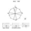
- Demodulation is preferably performed based on the exemplarily phasor diagram shown in Fig. 3. As shown, this phasor diagram includes a predetermined number of sectional basic symbol regions and a predetermined number of sectional threshold symbol regions. For illustrative purposes only, 4 basic symbol regions and 4 threshold symbol regions are shown, with the threshold symbol regions situated between the basic symbol regions respectively. The range of the threshold symbol regions should be optimized in order to maximize MPSK demodulation performance.
- the MPSK demodulator 50 performs a demodulation using a hard-decision value. That is, each signal of a packet belongs to one of the 8 symbol regions of the phasor diagram and is converted into a symbol value of the region to which it belongs. Each symbol region may be determined as follows.
- each signal of a packet contains I and Q signals (or orthogonal coefficients).
- the I and Q signals correspond to a coordinate value which indicates a position of the packet signal when the packet signal is expressed on the phasor diagram.
- the MPSK demodulator 50 converts the packet signal into one of four basic symbols (0, 1, 2, 3) or converts it into one of four threshold symbols (0&1, 1&2, 2&3, 3&0).
- the threshold symbol (0&1) has a high possibility that a noise component is mixed in the basic symbol (0) or the basic symbol (1).
- the threshold symbol (1&2) has a high possibility that a noise component is mixed in the basic symbol (1) or the basic symbol (2).
- the threshold symbol (2&3) has a high possibility that a noise component is mixed in the basic symbol (2) or the basic symbol (3).
- the threshold symbol (3&0) has a high possibility that a noise component is mixed in the basic symbol (3) or the basic symbol (0).
- a packet signal belonging to one of the basic symbol regions is expressed only by a corresponding symbol, while a packet signal belonging to one of the threshold symbol regions is expressed by two basic symbols which adjoin the corresponding threshold symbol region. For example, if a packet signal is positioned at the basic symbol region (0), the packet signal is converted into a basic symbol (0). However, if a packet signal is positioned at the threshold symbol region (3&0) between the basic symbol region (3) and the basic symbol region (0), the packet signal is converted into a threshold symbol having both the basic symbol (3) value and the basic symbol (0) value.
- the signals of the re-transmitted packet from the MPSK demodulator 50 are sent to the decoder 70, and the decoder decodes the signals and checks whether there is an error in the re-transmitted packet.
- a threshold symbol may be processed by being regarded as an erase symbol. If there is an error in the error-checking process, the signals output from the MPSK demodulator 50 are sent to the diversity combiner 60.
- Figure 5A through 5C illustrate some of the techniques the diversity Combiner of the invention may implement and their results. This explanation is provided on a signal-by-signal basis with the understanding that all signals in the retransmitted packet may be combined with corresponding signals in the original packet.
- the diversity combiner 60 When a signal output from the MPSK demodulator 50 (that is, a signal from the demodulated re-transmitted packet) is transmitted to the diversity combiner 60, the diversity combiner 60 performs a logical operation on the symbol of the demodulated re-transmitted packet signal and the symbol of the corresponding signal in the original packet.
- This logical operation preferably includes an AND operation, but those skilled in the art can appreciate that other logic gate arrangements may also be used as long as these arrangements provide an output which may be used in accordance with the invention as described below.
- Figure 5A is an exemplary view of a diversity combining method in the case where the number of the combining result value is 0'
- Figure 5B is an exemplary view of a case where the number of operation result value is '2'
- Figure 5C is an exemplary view of a case where the number of operation result value is '1'.
- the symbols are decoded but are not regarded as erase symbols.
- Figure 5C if two compared symbols (A,A') are identical and are basic symbols, the number of the operation result value is '1'. Then, the decoder 70 decodes the corresponding symbols normally, i.e., based on their actual symbols. There symbols are therefore not considered erase symbols.
- the decoder 70 normally decodes the corresponding symbols.
- the decoder 70 normally decodes the corresponding symbols, i.e., not as erase symbols.
- the decoder 70 regards the corresponding symbol as an erase symbol and performs an erase-error correction decoding only if the number of the ANDing result value is '0' or '2'.
- the diversity combining method of the present invention may therefore be applied every type of erase-error correction decoding.
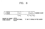
- the result of this combining step is a combined packet such as shown in Fig. 6.
- the shaded signal A 2 has been given an erase symbol because one of the aforementioned conditions has been satisfied for assigning an erase symbol.
- FIG. 7 is a flow chart showing steps included in a diversity combining method in accordance with the present invention.
- the method includes as an initial step receiving a re-transmitted packet (S10) and demodulating the received packet using MPSK modulation (S20). Next, a symbol generated for each signal in the packet from demodulation is decoded (S30). Next, it is determined whether an error exists in the re-transmitted packet signal. When any error is detected in the decoded signal, the generated symbol is combined with a symbol of a corresponding signal in the original packet (S40). Then, a second decoding step (S50) is performed in which a symbol of the re-transmitted packet is decoded based on the combining result. In step (S60), when an error is detected from the secondly decoded signal, a packet re-transmission is requested.
- step S10 if a re-transmitted packet is received (step S10), the re-transmitted packet is demodulated according to the demodulation method of the present invention (step S20). Erase-error correction decoding and error detecting are then performed on symbols generated for the signals in the demodulated packet (step S30). If there is an error in the demodulated re-transmitted packet, diversity combiner 60 ANDs the symbol generated from the demodulated re-transmitted packet with the symbol in the original packet on a signal-by-signal basis. This results in the formation of a combined packet. Then, erase-error correction decoding and error detecting are performed on the re-transmitted (or Combined) packet with reference to the operation result (step S50).
- the error detecting may be performed by an error detector (not shown) or a controller (not shown) at the next stage of the decoder 70.
- the error detecting step and the decoding steps are separately performed steps, but for this explanation's sake it is considered that decoder 70 also performs the error detecting function.
- the MPSK demodulator 50 demodulates the re-transmitted packet according to the demodulation method proposed in the present invention (step S20). Namely the signal demodulated by the MPSK demodulator 50 is expressed as one of 8 symbols (1, 0&1, 1, 1&2, 2, 2&3, 3, 3&0) depending on the position of the packet signal appearing on the phasor diagram.
- the demodulated signal (or the symbol) is decoded by the decoder 70 (step S30).
- the decoder 70 regards a threshold symbol among symbols outputted by the MPSK demodulator 50 as an erased symbol and decodes it.
- the decoder 70 also checks whether there is an error in the re-transmitted packet which has been through the decoding process.
- the symbol of the re-transmitted packet output from the MPSK demodulator 50 is sent to the diversity combiner 60. Then, the diversity combiner 60 ANDs the symbol of the re-transmitted packet with a symbol of the corresponding original packet (step S40).
- the decoder 70 performs decoding and error detecting with reference to the operation result of the diversity combiner 60 (step S50). That is, if the number of the ANDing result value is '0' or '2', the decoder 70 regards the corresponding symbol as an erased symbol and performs decoding of a combined packet and error detection. If the re-transmitted packet is determined to have an error again in the step S50, the receiving party requests re-transmission of the corresponding packet from the transmitting party (stepS60). If, however, the re-transmitted packet is determined to have no error in the step S30 or in the step S50, the error control routine for the corresponding packet is terminated.
- the first error control process is performed through the MPSK demodulation step (S20) and the erase-error correction decoding step (S30), and the second error control process is performed through the diversity combining step (S40) and the erase-error correction decoding step (S50).
- the error control routine is designed such that the diversity combining step (S40) is not performed if the error of the re-transmitted packet is correctable in the first error control process. This is advantageous in that the re-transmitted packet can be quickly processed without an error.
- the diversity combining method of the present invention thus has the following advantages.
Landscapes
- Engineering & Computer Science (AREA)
- Computer Networks & Wireless Communication (AREA)
- Signal Processing (AREA)
- Digital Transmission Methods That Use Modulated Carrier Waves (AREA)
- Radio Transmission System (AREA)
- Detection And Prevention Of Errors In Transmission (AREA)
Abstract
Description
- The present invention generally relates to a communications system, and more particularly to a system and method for performing an error control operation in a radio communications system.
- Figure 1 shows a receiver in a conventional wireless communications system. This receiver includes an
MPSK demodulator 10 for demodulating a re-transmitted packet signal using a soft decision method, a diversity combiner 20 for combining a symbol generated from thedemodulator 10 with a previously received error packet signal (hereinafter referred to as 'original packet signal'), and adecoder 30 for decoding the combined symbol. - The MPSK (M-ary Phase Shift Keying) demodulator performs a modulation method in which only phase is changed with amplitude, a frequency of a carrier is constantly maintained, and a plurality of bits are transmitted at one time. As the signal is modulated, 2-bit or 4-bit data is transmitted by one modulation signal. That is, an unmodulated signal is transmitted one bit at a time but in the case of 4 binary-
PSK modulations 2 bits are transmitted at a time using a phase change of the signal. 16 binary-PSK allows transmission of 4 bits at a time. - MPSK modulation is based on the assumption that M=2n where M is the number of modulation signals (or symbols) with different phases and n signifies the number if bits transmittable at a time. In this modulation scheme, a phase difference between carriers is 2π/M and can be implemented using an orthogonal representation system.
- The diversity combiner performs a symbol diversity combining technique. According to this technique, symbols with noise are held, not discarded, and are then effectively combined with the same symbols which have been re-transmitted in order to control an error and thereby heighten reliability of the symbols. Adoption of a symbol diversity combining method in a radio communication system is desirable because it increases reliability of the symbols. Thus, various diversity combining methods have been proposed such as an equal-gaining-combining method and a maximal-ratio-combining, method.
- Among these, the maximal-ratio-combining method is considered the most effective. This method adds ratios of the sizes of signals and then maximizes a signal-to-noise ratio in an environment where a signal plus an additive white Gaussian noise is received. The maximal-ratio-combining method has excellent performance but its calculation method is very complicated because it uses a soft-decision value.
- In operation, the signal output from the MPSK demodulator (i.e. the symbol) is a value obtained by performing a soft-decision operation on a re-transmitted packet signal as received. This value is generally expressed as a real number with a decimal point. When the symbol is transmitted to the diversity combiner 20, the diversity combiner combines it with a symbol of an original packet. The combining process performed by the diversity combiner is expressed as follows:

wherein the weight value is a weight value of a channel which transmitted an original packet, the weight value 'Y' (0.8) is a weight value of a channel which transmitted a re-transmission packet, the symbol 'A' is a symbol of an original packet, the symbol 'B' (1,125) is a symbol of a re-transmission packet, and 1.768 is a result value output from the diversity combining process according to the MRC. - The result value (1.768) of the combining process is transmitted to the
decoder 30, and the decoder determines the re-transmitted packet signal using the received result value and performing error-correction decoding. Thedecoder 30 usually performs only an error-correction function. Though not shown in Figure 1, the MRC diversity combiner includes a channel estimator to overcome multipath fading. The channel estimator attempts to estimate a size of a channel through which received signals and phase information have passed. - The MRC diversity combiner of the conventional art has disadvantages. For example, this MRC requires use of the channel estimator. Also, this MRC is hard to implement due to use of the soft decision value in the symbol demodulation process and requires a very large amount of calculations to be performed, which translates into increased complexity. These calculations include multiplication and addition of real numbers below a decimal point and are performed in the MRC scores of times more than the bit logical operation of the present invention, described in detail below. The conventional art MRC is therefore very complex. In addition, in the MRC a channel estimated value, a soft-decision value, and a calculation result value are stored as real numbers. As a result memory space is wasted.
- An article by Jik Dong Kim et al. entitled "A Simple Packet Combining Technique in Frequency-Hopped Spread-Spectrum Multiple Access Communication Networks", published in Proceedings of the IEEE International Conference on Communications, 1997. ICC 97 Montreal, "Towards the Knowledge Millennium", vol. 3, pages 1207-1211, ISBN: 0-7803-3925-8, discloses a packet combining scheme suitable for use in FH/SSMA communication networks employing MFSK (M-ary frequency-shift-keying). The article recognizes that the desired signal tone in an original packet and a re-transmitted packet stays in the same position, while interfering tones vary randomly. In the combining stage, therefore, a tone-by-tone logical AND operation of each symbol of the packets is performed. An erasure is marked in the combined packet where the resulting symbol has more than one logic "1". Symbols having a single logic "1", on the other hand, are regarded as a correct symbol decision. The re-transmitted packet is first decoded by itself. If the decoding fails, a new packet is generated by the tone-by-tone logical AND operation between the currently received packet and the original packet (or a previously combined packet). This new packet is decoded again. If the decoding still fails, re-transmission of the packet must be requested.
- The present invention aims to provide a method and apparatus for performing a diversity operation which allows facilitated detection of errors, particularly in a QPSK-based communication system. To achieve this goal, the present invention provides a method for processing signals according to
claim 1 and a communications receiver according to claim 6. Preferred embodiments are given in the dependent sub-claims. - In one embodiment of the present invention, a logical operation diversity combining method includes: receiving and demodulating a re-transmitted packet, decoding a symbol generated from demodulation, combining the generated symbol with a symbol of an original packet when an error is detected from the decoded signal, decoding a symbol of the re-transmitted packet based on the combining result, and when an error is detected from the secondly decoded signal requesting a packet re-transmission. By performing a logical operation in the combining step instead of the computations in a conventional MRC diversity combiner, a channel estimator may be eliminated and efficiency increased.
- Figure 1 is a drawing illustrating a construction of receiving system in accordance with the conventional art.
- Figure 2 is a drawing illustrating a construction of a receiving system in accordance with the present invention.
- Figure 3 is a drawing illustrating an MPSK demodulation in accordance with the present invention.
- Figures 4A and 4B show examples of original and re-transmitted packets that maybe combined in accordance with the present invention.
- Figure 5A is an exemplary view of a diversity combining method and of a case where the number of operation result value is '0' in accordance with the present invention; Figure 5B is an exemplary view of a case that the number of operation result value is '2'; and Figure 5C is an exemplary view of a case that the number of operation result value is '1'.
- Figure 6 shows an example of a combined packet formed by the present invention as a result of combining the packets of Figures 4A and 4B.
- Figure 7 is a flow chart of the diversity combining method in accordance with the present invention.
- Figure 2 shows a receiving system in accordance with one embodiment of the present invention. The system includes an
MPSK demodulator 50 for demodulating a re-transmitted packet according to hard-decision method, a diversity combiner 60 for combining a symbol generated from thedemodulator 50 with a symbol of an original packet, and adecoder 70 for decoding a symbol of the re-transmitted packet based on a result output from the combiner. The diversity combiner 60 performs a combining process based on a logical operation, and thedecoder 70 may be an erase-error correction decoder. Preferably, the logical operation includes a logical AND of the combined symbols. - Figure 3 is a conceptual diagram how an MPSK demodulation may be performed in accordance with the present invention. As shown, this demodulation method uses QPSK (Quadrature Phase Shift Keying) techniques. Before describing this step of the invention, it is initially noted that before receiving the re-transmitted packet an original packet was received containing errors. A re-transmission request for the packet was then sent from the receiver to the transmitter. The re-transmitted packet is then subsequently received. In accordance with one embodiment of the invention, each of the original and re-transmitted packets includes a plurality of signals. The signals in the original packet are illustratively shown as a1,1, a1,2 ... a1,n in Fig. 4A and the signals in the re-transmitted packet are illustratively shown as a2,1, a2,2 ... a2,n in Fig. 4B.
- In performing the MPSK demodulation step of the present invention, it is noted that demodulation is performed on a signal-by-signal basis for each signal in the re-transmitted packet. Demodulation is preferably performed based on the exemplarily phasor diagram shown in Fig. 3. As shown, this phasor diagram includes a predetermined number of sectional basic symbol regions and a predetermined number of sectional threshold symbol regions. For illustrative purposes only, 4 basic symbol regions and 4 threshold symbol regions are shown, with the threshold symbol regions situated between the basic symbol regions respectively. The range of the threshold symbol regions should be optimized in order to maximize MPSK demodulation performance.
- In accordance with the present invention, the
MPSK demodulator 50 performs a demodulation using a hard-decision value. That is, each signal of a packet belongs to one of the 8 symbol regions of the phasor diagram and is converted into a symbol value of the region to which it belongs. Each symbol region may be determined as follows. - First, it is noted that each signal of a packet contains I and Q signals (or orthogonal coefficients). The I and Q signals correspond to a coordinate value which indicates a position of the packet signal when the packet signal is expressed on the phasor diagram.
- According to the symbol region to which the packet signal belongs, the
MPSK demodulator 50 converts the packet signal into one of four basic symbols (0, 1, 2, 3) or converts it into one of four threshold symbols (0&1, 1&2, 2&3, 3&0). The threshold symbol (0&1) has a high possibility that a noise component is mixed in the basic symbol (0) or the basic symbol (1). The threshold symbol (1&2) has a high possibility that a noise component is mixed in the basic symbol (1) or the basic symbol (2). The threshold symbol (2&3) has a high possibility that a noise component is mixed in the basic symbol (2) or the basic symbol (3). The threshold symbol (3&0) has a high possibility that a noise component is mixed in the basic symbol (3) or the basic symbol (0). - From this explanation, it is clear that in accordance with at least one embodiment of the invention, a packet signal belonging to one of the basic symbol regions is expressed only by a corresponding symbol, while a packet signal belonging to one of the threshold symbol regions is expressed by two basic symbols which adjoin the corresponding threshold symbol region. For example, if a packet signal is positioned at the basic symbol region (0), the packet signal is converted into a basic symbol (0). However, if a packet signal is positioned at the threshold symbol region (3&0) between the basic symbol region (3) and the basic symbol region (0), the packet signal is converted into a threshold symbol having both the basic symbol (3) value and the basic symbol (0) value.
- The signals of the re-transmitted packet from the
MPSK demodulator 50 are sent to thedecoder 70, and the decoder decodes the signals and checks whether there is an error in the re-transmitted packet. During the decoding process, a threshold symbol may be processed by being regarded as an erase symbol. If there is an error in the error-checking process, the signals output from theMPSK demodulator 50 are sent to thediversity combiner 60. - Figure 5A through 5C illustrate some of the techniques the diversity Combiner of the invention may implement and their results. This explanation is provided on a signal-by-signal basis with the understanding that all signals in the retransmitted packet may be combined with corresponding signals in the original packet.
- When a signal output from the MPSK demodulator 50 (that is, a signal from the demodulated re-transmitted packet) is transmitted to the
diversity combiner 60, thediversity combiner 60 performs a logical operation on the symbol of the demodulated re-transmitted packet signal and the symbol of the corresponding signal in the original packet. This logical operation preferably includes an AND operation, but those skilled in the art can appreciate that other logic gate arrangements may also be used as long as these arrangements provide an output which may be used in accordance with the invention as described below. - Figure 5A is an exemplary view of a diversity combining method in the case where the number of the combining result value is 0', Figure 5B is an exemplary view of a case where the number of operation result value is '2', and Figure 5C is an exemplary view of a case where the number of operation result value is '1'.
- In Figure 5A if two compared symbols are different (0,2), the number of the operation result value is '0'. Then, the
decoder 70 regards the corresponding symbols as erase symbols and decodes them. - In Figure 5B, if two compared symbols are identical to each other and are threshold symbols, the number of the operation result value is '2'. Then, the
decoder 70 regards the corresponding symbols as erase symbols and decodes them. - In the remaining cases, the symbols are decoded but are not regarded as erase symbols. In Figure 5C, if two compared symbols (A,A') are identical and are basic symbols, the number of the operation result value is '1'. Then, the
decoder 70 decodes the corresponding symbols normally, i.e., based on their actual symbols. There symbols are therefore not considered erase symbols. - If the two compared symbols (B, B') are different threshold symbols (0&1, 1&2) but neighboring symbols having the same basic symbol (1) therebetween, the number of the operation result value is '1' and the
decoder 70 normally decodes the corresponding symbols. - If one (C) of the two symbols (C, C') is a basic symbol (3) and the other symbol (C') is a threshold symbol (2&3) adjacent to the basic symbol (3), the number of the operation result value is '1' and the
decoder 70 normally decodes the corresponding symbols, i.e., not as erase symbols. - Thus, the
decoder 70 regards the corresponding symbol as an erase symbol and performs an erase-error correction decoding only if the number of the ANDing result value is '0' or '2'. The diversity combining method of the present invention may therefore be applied every type of erase-error correction decoding. - The result of this combining step is a combined packet such as shown in Fig. 6. In this packet, the shaded signal A2 has been given an erase symbol because one of the aforementioned conditions has been satisfied for assigning an erase symbol. The non-shaded signals, however, are not erase symbols but rather are given normal values (i.e., A i = a2,i and An-1 = a1,n-1 = a2,n-1).
- Figure 7 is a flow chart showing steps included in a diversity combining method in accordance with the present invention. The method includes as an initial step receiving a re-transmitted packet (S10) and demodulating the received packet using MPSK modulation (S20). Next, a symbol generated for each signal in the packet from demodulation is decoded (S30). Next, it is determined whether an error exists in the re-transmitted packet signal. When any error is detected in the decoded signal, the generated symbol is combined with a symbol of a corresponding signal in the original packet (S40). Then, a second decoding step (S50) is performed in which a symbol of the re-transmitted packet is decoded based on the combining result. In step (S60), when an error is detected from the secondly decoded signal, a packet re-transmission is requested.
- A more detailed description of a preferred embodiment of the diversity combining method of the present invention will now be provided. In this method, if a re-transmitted packet is received (step S10), the re-transmitted packet is demodulated according to the demodulation method of the present invention (step S20). Erase-error correction decoding and error detecting are then performed on symbols generated for the signals in the demodulated packet (step S30). If there is an error in the demodulated re-transmitted packet,
diversity combiner 60 ANDs the symbol generated from the demodulated re-transmitted packet with the symbol in the original packet on a signal-by-signal basis. This results in the formation of a combined packet. Then, erase-error correction decoding and error detecting are performed on the re-transmitted (or Combined) packet with reference to the operation result (step S50). - The error detecting may be performed by an error detector (not shown) or a controller (not shown) at the next stage of the
decoder 70. The error detecting step and the decoding steps are separately performed steps, but for this explanation's sake it is considered thatdecoder 70 also performs the error detecting function. - The diversity combining method of the present invention will now be described in detail with reference to Figures 2, 3, 4 and 5. When the re-transmitted packet is received in (step S10), the
MPSK demodulator 50 demodulates the re-transmitted packet according to the demodulation method proposed in the present invention (step S20). Namely the signal demodulated by theMPSK demodulator 50 is expressed as one of 8 symbols (1, 0&1, 1, 1&2, 2, 2&3, 3, 3&0) depending on the position of the packet signal appearing on the phasor diagram. - For each signal in the re-transmitted packet, the demodulated signal (or the symbol) is decoded by the decoder 70 (step S30). At this time, the
decoder 70 regards a threshold symbol among symbols outputted by theMPSK demodulator 50 as an erased symbol and decodes it. Thedecoder 70 also checks whether there is an error in the re-transmitted packet which has been through the decoding process. - If there is an error in the re-transmitted packet, the symbol of the re-transmitted packet output from the
MPSK demodulator 50 is sent to thediversity combiner 60. Then, thediversity combiner 60 ANDs the symbol of the re-transmitted packet with a symbol of the corresponding original packet (step S40). - The
decoder 70 performs decoding and error detecting with reference to the operation result of the diversity combiner 60 (step S50). That is, if the number of the ANDing result value is '0' or '2', thedecoder 70 regards the corresponding symbol as an erased symbol and performs decoding of a combined packet and error detection. If the re-transmitted packet is determined to have an error again in the step S50, the receiving party requests re-transmission of the corresponding packet from the transmitting party (stepS60). If, however, the re-transmitted packet is determined to have no error in the step S30 or in the step S50, the error control routine for the corresponding packet is terminated. - As so far described, in the present invention the first error control process is performed through the MPSK demodulation step (S20) and the erase-error correction decoding step (S30), and the second error control process is performed through the diversity combining step (S40) and the erase-error correction decoding step (S50).
- More specifically, the error control routine is designed such that the diversity combining step (S40) is not performed if the error of the re-transmitted packet is correctable in the first error control process. This is advantageous in that the re-transmitted packet can be quickly processed without an error.
- The diversity combining method of the present invention thus has the following advantages. First, since the diversity combining is implemented by the logical AND operation, the operation process is very simple compared to that of the conventional method such as the MRC and uses less memory. Besides, since the hard-decision value is used in the demodulation process, the diversity combining method can be easily implemented. Second, the diversity combining method if the present invention can be easily adapted to any erase-error correction code system and does not need a channel estimator. As a result, the invention is far less complex to implement compared with the conventional art.
- The foregoing embodiments and advantages are merely exemplary and are not to be construed as limiting the present invention. The present teaching can be readily applied to other types of apparatuses. The description of the present invention is intended to be illustrative, and not to limit the scope of the claims. Many alternatives, modifications, and variations will be apparent to those skilled in the art.
Claims (9)
- A method for processing signals received in a communications system, the method comprising:- determining (S20) a symbol for each of a plurality of signals contained in a re-transmitted packet,- forming (S40) a combined packet by logically ANDing the symbol for each signal in the re-transmitted packet with a symbol for a corresponding signal in an original packet;- determining, for each symbol of the combined packet, whether the symbol is an erase symbol or a non-erase symbol;- erase-error correction decoding (S50) the combined packet based on the erase and non-erase symbols;the method characterized in that:- the symbol for each signal in the re-transmitted packet is determined by determining I and Q components corresponding to the respective signal, locating the I and Q components on a phasor diagram, and assigning a symbol to the respective signal based on a location of the I and Q components on the phasor diagram, wherein the phasor diagram includes a predetermined number of basic regions and a predetermined number of threshold regions, the threshold regions situated between respective pairs of basic regions, the basic regions having respective basic symbols assigned thereto so that a signal belonging to one of the basic regions is expressed by a corresponding basic symbol, the threshold regions having respective threshold symbols assigned thereto such that a signal belonging to one of the threshold regions is expressed by the basic symbols of the basic regions adjoining the threshold region; and- a symbol of the combined packet is determined to be an erase symbol if the corresponding symbols of the re-transmitted packet and the original packet are non-matching basic symbols or matching threshold symbols.
- The method of claim 1, wherein the symbols assigned to respective ones of the basic regions and the threshold regions are QPSK values.
- The method of claim 1, further comprising:demodulating (S20) the re-transmitted packet based on a hard-decision value.
- The method of claim 1, further comprising:- erase-error correction decoding (S30) the re-transmitted packet while regarding threshold symbols as erase symbols; and- forming the combined packet if a non-correctable error is detected in the re-transmitted packet.
- The method of claim 1, further comprising:requesting (S60) a packet re-transmission if an error is detected in the combined packet.
- A communications receiver, comprising:- a processor (50) configured to determine a symbol for each of a plurality of signals contained in a re-transmitted packet;- a combiner (60) configured to form a combined packet by logically ANDing the symbol for each signal in the re-transmitted packet with a symbol for a corresponding signal in an original packet and to determine, for each symbol of the combined packet, whether the symbol is an erase symbol or a non-erase symbol; and- a decoder (70) configured to erase-error correction decode the combined packet based on the erase and non-erase symbols;the communications receiver characterized in that :- the processor is configured to determine the symbol for each signal in the re-transmitted packet by determining I and Q components corresponding to the respective signal, locating the I and Q components on a phasor diagram, and assigning a symbol to the respective signal based on a location of the I and Q components on the phasor diagram, wherein the phasor diagram includes a predetermined number of basic regions and a predetermined number of threshold regions, the threshold regions situated between respective pairs of basic regions, the basic regions having respective basic symbols assigned thereto so that a signal belonging to one of the basic regions is expressed by a corresponding basic symbol, the threshold regions having respective threshold symbols assigned thereto such that a signal belonging to one of the threshold regions is expressed by the basic symbols of the basic regions adjoining the threshold region; and- the combiner is configured to determine a symbol of the combined packet to be an erase symbol if the corresponding symbols of the re-transmitted packet and the original packet are non-matching basic symbols or matching threshold symbols.
- The communications receiver of claim 6, further comprising:a demodulator (50) configured to demodulate the re-transmitted packet based on a hard-decision value.
- The communications receiver of claim 6, wherein the decoder (70) is configured to erase-error correction decode the re-transmitted packet while regarding threshold symbols as erase symbols; and wherein the combiner (60) is configured to form the combined packet if a non-correctable error is detected in the re-transmitted packet.
- The communications receiver of claim 6, further comprising means for requesting a packet re-transmission if an error is detected in the combined packet.
Applications Claiming Priority (2)
| Application Number | Priority Date | Filing Date | Title |
|---|---|---|---|
| KR2002062141 | 2002-10-11 | ||
| KR1020020062141A KR100548314B1 (en) | 2002-10-11 | 2002-10-11 | Method for error control of receiver system of wireless communication |
Publications (2)
| Publication Number | Publication Date |
|---|---|
| EP1408640A1 EP1408640A1 (en) | 2004-04-14 |
| EP1408640B1 true EP1408640B1 (en) | 2007-08-29 |
Family
ID=32026144
Family Applications (1)
| Application Number | Title | Priority Date | Filing Date |
|---|---|---|---|
| EP03006753A Expired - Lifetime EP1408640B1 (en) | 2002-10-11 | 2003-03-25 | Diversity combining for phase modulated signals |
Country Status (7)
| Country | Link |
|---|---|
| US (1) | US7542409B2 (en) |
| EP (1) | EP1408640B1 (en) |
| JP (1) | JP3836803B2 (en) |
| KR (1) | KR100548314B1 (en) |
| CN (1) | CN100508511C (en) |
| AT (1) | ATE372004T1 (en) |
| DE (1) | DE60315935T2 (en) |
Families Citing this family (4)
| Publication number | Priority date | Publication date | Assignee | Title |
|---|---|---|---|---|
| US8942218B2 (en) * | 2006-09-29 | 2015-01-27 | Intel Corporation | Retransmission of data using sub-carrier frequency permutation |
| KR101531502B1 (en) * | 2007-12-11 | 2015-06-26 | 엘지전자 주식회사 | Method of Error control |
| KR101467788B1 (en) | 2007-12-11 | 2014-12-03 | 엘지전자 주식회사 | Method and Apparatus of communication using Random Linear Coding |
| KR101490249B1 (en) | 2007-12-11 | 2015-02-05 | 엘지전자 주식회사 | Method and Apparatus of communication using soft decision |
Family Cites Families (13)
| Publication number | Priority date | Publication date | Assignee | Title |
|---|---|---|---|---|
| US5745502A (en) * | 1996-09-27 | 1998-04-28 | Ericsson, Inc. | Error detection scheme for ARQ systems |
| JPH10262281A (en) * | 1997-03-18 | 1998-09-29 | Toshiba Corp | Radio data transmission system provided with re-transmission control function |
| FI103540B (en) * | 1997-04-28 | 1999-07-15 | Nokia Mobile Phones Ltd | A method for transferring packet switched data from a mobile system |
| FI972987A (en) * | 1997-07-14 | 1999-01-15 | Nokia Telecommunications Oy | Reconstructing the transmitted data frame |
| JP3382891B2 (en) | 1999-07-02 | 2003-03-04 | エヌイーシービューテクノロジー株式会社 | Demodulation method and digital demodulation device for digitally processing phase modulated signal |
| SE0000897D0 (en) * | 2000-03-17 | 2000-03-17 | Ericsson Telefon Ab L M | Methods in a communication system |
| US6977972B1 (en) * | 2000-07-12 | 2005-12-20 | Sharp Laboratories Of America, Inc. | Method of hybrid soft/hard decision demodulation of signals with multilevel modulation |
| US6983029B2 (en) * | 2000-12-15 | 2006-01-03 | Maxim Integrated Products, Inc. | Blind channel estimation and data detection for PSK OFDM-based receivers |
| US7110351B2 (en) * | 2000-12-19 | 2006-09-19 | Nortel Networks Limited | Enhanced ARQ with OFDM modulation symbols |
| CN100393021C (en) * | 2001-02-21 | 2008-06-04 | 松下电器产业株式会社 | Hybrid ARQ method with single constellation rearrangement |
| KR100800885B1 (en) * | 2001-08-13 | 2008-02-04 | 삼성전자주식회사 | Demodulation apparatus and method for communication using multi level modulation |
| KR100464325B1 (en) * | 2001-10-15 | 2005-01-03 | 삼성전자주식회사 | Method and apparatus for transmitting/receiving for re-transmission of packet in mobile communication system |
| KR100584170B1 (en) * | 2002-07-11 | 2006-06-02 | 재단법인서울대학교산학협력재단 | Turbo Coded Hybrid Automatic Repeat Request System And Error Detection Method |
-
2002
- 2002-10-11 KR KR1020020062141A patent/KR100548314B1/en not_active IP Right Cessation
-
2003
- 2003-03-25 EP EP03006753A patent/EP1408640B1/en not_active Expired - Lifetime
- 2003-03-25 DE DE60315935T patent/DE60315935T2/en not_active Expired - Lifetime
- 2003-03-25 AT AT03006753T patent/ATE372004T1/en not_active IP Right Cessation
- 2003-03-27 US US10/397,374 patent/US7542409B2/en not_active Expired - Fee Related
- 2003-04-01 JP JP2003098618A patent/JP3836803B2/en not_active Expired - Fee Related
- 2003-04-22 CN CNB031220487A patent/CN100508511C/en not_active Expired - Fee Related
Non-Patent Citations (1)
| Title |
|---|
| None * |
Also Published As
| Publication number | Publication date |
|---|---|
| DE60315935T2 (en) | 2008-07-31 |
| CN100508511C (en) | 2009-07-01 |
| JP3836803B2 (en) | 2006-10-25 |
| KR20040033203A (en) | 2004-04-21 |
| CN1489351A (en) | 2004-04-14 |
| ATE372004T1 (en) | 2007-09-15 |
| KR100548314B1 (en) | 2006-02-02 |
| EP1408640A1 (en) | 2004-04-14 |
| US20040071093A1 (en) | 2004-04-15 |
| US7542409B2 (en) | 2009-06-02 |
| DE60315935D1 (en) | 2007-10-11 |
| JP2004135255A (en) | 2004-04-30 |
Similar Documents
| Publication | Publication Date | Title |
|---|---|---|
| EP1253759B1 (en) | Radio transmitter, radio receiver, and multilevel modulation communication system | |
| US7400687B2 (en) | Multicarrier communication apparatus and multicarrier communication method | |
| EP1204256B1 (en) | Adaptive modulation communication system | |
| EP1422861B1 (en) | Transmission / reception apparatus and transmission / reception method | |
| US20070147487A1 (en) | Apparatus, method and computer program product providing dynamic modulation setting combined with power sequences | |
| EP1011245A1 (en) | Transmitter and receiver and data transmission method | |
| US6993092B1 (en) | Transmission apparatus, reception apparatus and digital radio communication method | |
| US7672394B2 (en) | Transmission apparatus and transmission method | |
| US20080292017A1 (en) | Modulation of Data Streams With Constellation Subset Mapping | |
| US5809043A (en) | Method and apparatus for decoding block codes | |
| US7180962B2 (en) | Apparatus and method for demodulation using detection of channel adaptive modulation scheme | |
| EP1408640B1 (en) | Diversity combining for phase modulated signals | |
| JP4213660B2 (en) | Wireless communication system and wireless transmitter | |
| JP3233092B2 (en) | Modulation system and wireless communication system using the same | |
| US7630457B2 (en) | Method and apparatus for demodulating a received signal within a coded system | |
| EP1912368A1 (en) | Method of decoding of a received multidimensional signal and corresponding device | |
| JP4534037B2 (en) | OFDM communication device | |
| KR100546801B1 (en) | Apparatus and method for demodulation using detection of channel adaptive modulation scheme | |
| JP2006074081A (en) | Ofdm communication apparatus | |
| JP2002124998A (en) | Receiving device | |
| Moriyama | Reduction of errors due to random FM noise | |
| JP2004007785A (en) | Modulation system and transmitter | |
| JP2001358789A (en) | Modulation system, its receiver and radio communication system using the same | |
| JP2004007786A (en) | Receiver |
Legal Events
| Date | Code | Title | Description |
|---|---|---|---|
| PUAI | Public reference made under article 153(3) epc to a published international application that has entered the european phase |
Free format text: ORIGINAL CODE: 0009012 |
|
| AK | Designated contracting states |
Kind code of ref document: A1 Designated state(s): AT BE BG CH CY CZ DE DK EE ES FI FR GB GR HU IE IT LI LU MC NL PT RO SE SI SK TR |
|
| AX | Request for extension of the european patent |
Extension state: AL LT LV MK |
|
| 17P | Request for examination filed |
Effective date: 20040910 |
|
| AKX | Designation fees paid |
Designated state(s): AT BE BG CH CY CZ DE DK EE ES FI FR GB GR HU IE IT LI LU MC NL PT RO SE SI SK TR |
|
| 17Q | First examination report despatched |
Effective date: 20050609 |
|
| GRAP | Despatch of communication of intention to grant a patent |
Free format text: ORIGINAL CODE: EPIDOSNIGR1 |
|
| GRAS | Grant fee paid |
Free format text: ORIGINAL CODE: EPIDOSNIGR3 |
|
| GRAA | (expected) grant |
Free format text: ORIGINAL CODE: 0009210 |
|
| AK | Designated contracting states |
Kind code of ref document: B1 Designated state(s): AT BE BG CH CY CZ DE DK EE ES FI FR GB GR HU IE IT LI LU MC NL PT RO SE SI SK TR |
|
| REG | Reference to a national code |
Ref country code: GB Ref legal event code: FG4D |
|
| REG | Reference to a national code |
Ref country code: CH Ref legal event code: EP |
|
| REG | Reference to a national code |
Ref country code: IE Ref legal event code: FG4D |
|
| REG | Reference to a national code |
Ref country code: SE Ref legal event code: TRGR |
|
| REF | Corresponds to: |
Ref document number: 60315935 Country of ref document: DE Date of ref document: 20071011 Kind code of ref document: P |
|
| ET | Fr: translation filed | ||
| PG25 | Lapsed in a contracting state [announced via postgrant information from national office to epo] |
Ref country code: ES Free format text: LAPSE BECAUSE OF FAILURE TO SUBMIT A TRANSLATION OF THE DESCRIPTION OR TO PAY THE FEE WITHIN THE PRESCRIBED TIME-LIMIT Effective date: 20071210 |
|
| PG25 | Lapsed in a contracting state [announced via postgrant information from national office to epo] |
Ref country code: LI Free format text: LAPSE BECAUSE OF FAILURE TO SUBMIT A TRANSLATION OF THE DESCRIPTION OR TO PAY THE FEE WITHIN THE PRESCRIBED TIME-LIMIT Effective date: 20070829 Ref country code: AT Free format text: LAPSE BECAUSE OF FAILURE TO SUBMIT A TRANSLATION OF THE DESCRIPTION OR TO PAY THE FEE WITHIN THE PRESCRIBED TIME-LIMIT Effective date: 20070829 Ref country code: CH Free format text: LAPSE BECAUSE OF FAILURE TO SUBMIT A TRANSLATION OF THE DESCRIPTION OR TO PAY THE FEE WITHIN THE PRESCRIBED TIME-LIMIT Effective date: 20070829 |
|
| REG | Reference to a national code |
Ref country code: CH Ref legal event code: PL |
|
| PG25 | Lapsed in a contracting state [announced via postgrant information from national office to epo] |
Ref country code: BE Free format text: LAPSE BECAUSE OF FAILURE TO SUBMIT A TRANSLATION OF THE DESCRIPTION OR TO PAY THE FEE WITHIN THE PRESCRIBED TIME-LIMIT Effective date: 20070829 |
|
| PG25 | Lapsed in a contracting state [announced via postgrant information from national office to epo] |
Ref country code: GR Free format text: LAPSE BECAUSE OF FAILURE TO SUBMIT A TRANSLATION OF THE DESCRIPTION OR TO PAY THE FEE WITHIN THE PRESCRIBED TIME-LIMIT Effective date: 20071130 Ref country code: DK Free format text: LAPSE BECAUSE OF FAILURE TO SUBMIT A TRANSLATION OF THE DESCRIPTION OR TO PAY THE FEE WITHIN THE PRESCRIBED TIME-LIMIT Effective date: 20070829 |
|
| PG25 | Lapsed in a contracting state [announced via postgrant information from national office to epo] |
Ref country code: PT Free format text: LAPSE BECAUSE OF FAILURE TO SUBMIT A TRANSLATION OF THE DESCRIPTION OR TO PAY THE FEE WITHIN THE PRESCRIBED TIME-LIMIT Effective date: 20080129 Ref country code: SK Free format text: LAPSE BECAUSE OF FAILURE TO SUBMIT A TRANSLATION OF THE DESCRIPTION OR TO PAY THE FEE WITHIN THE PRESCRIBED TIME-LIMIT Effective date: 20070829 Ref country code: CZ Free format text: LAPSE BECAUSE OF FAILURE TO SUBMIT A TRANSLATION OF THE DESCRIPTION OR TO PAY THE FEE WITHIN THE PRESCRIBED TIME-LIMIT Effective date: 20070829 |
|
| PG25 | Lapsed in a contracting state [announced via postgrant information from national office to epo] |
Ref country code: RO Free format text: LAPSE BECAUSE OF FAILURE TO SUBMIT A TRANSLATION OF THE DESCRIPTION OR TO PAY THE FEE WITHIN THE PRESCRIBED TIME-LIMIT Effective date: 20070829 |
|
| PLBE | No opposition filed within time limit |
Free format text: ORIGINAL CODE: 0009261 |
|
| STAA | Information on the status of an ep patent application or granted ep patent |
Free format text: STATUS: NO OPPOSITION FILED WITHIN TIME LIMIT |
|
| 26N | No opposition filed |
Effective date: 20080530 |
|
| PG25 | Lapsed in a contracting state [announced via postgrant information from national office to epo] |
Ref country code: MC Free format text: LAPSE BECAUSE OF NON-PAYMENT OF DUE FEES Effective date: 20080331 |
|
| PG25 | Lapsed in a contracting state [announced via postgrant information from national office to epo] |
Ref country code: EE Free format text: LAPSE BECAUSE OF FAILURE TO SUBMIT A TRANSLATION OF THE DESCRIPTION OR TO PAY THE FEE WITHIN THE PRESCRIBED TIME-LIMIT Effective date: 20070829 Ref country code: IE Free format text: LAPSE BECAUSE OF NON-PAYMENT OF DUE FEES Effective date: 20080325 |
|
| PG25 | Lapsed in a contracting state [announced via postgrant information from national office to epo] |
Ref country code: SI Free format text: LAPSE BECAUSE OF FAILURE TO SUBMIT A TRANSLATION OF THE DESCRIPTION OR TO PAY THE FEE WITHIN THE PRESCRIBED TIME-LIMIT Effective date: 20070829 |
|
| PG25 | Lapsed in a contracting state [announced via postgrant information from national office to epo] |
Ref country code: CY Free format text: LAPSE BECAUSE OF FAILURE TO SUBMIT A TRANSLATION OF THE DESCRIPTION OR TO PAY THE FEE WITHIN THE PRESCRIBED TIME-LIMIT Effective date: 20070829 |
|
| PG25 | Lapsed in a contracting state [announced via postgrant information from national office to epo] |
Ref country code: BG Free format text: LAPSE BECAUSE OF FAILURE TO SUBMIT A TRANSLATION OF THE DESCRIPTION OR TO PAY THE FEE WITHIN THE PRESCRIBED TIME-LIMIT Effective date: 20071129 |
|
| PG25 | Lapsed in a contracting state [announced via postgrant information from national office to epo] |
Ref country code: LU Free format text: LAPSE BECAUSE OF NON-PAYMENT OF DUE FEES Effective date: 20080325 Ref country code: HU Free format text: LAPSE BECAUSE OF FAILURE TO SUBMIT A TRANSLATION OF THE DESCRIPTION OR TO PAY THE FEE WITHIN THE PRESCRIBED TIME-LIMIT Effective date: 20080301 |
|
| PG25 | Lapsed in a contracting state [announced via postgrant information from national office to epo] |
Ref country code: TR Free format text: LAPSE BECAUSE OF FAILURE TO SUBMIT A TRANSLATION OF THE DESCRIPTION OR TO PAY THE FEE WITHIN THE PRESCRIBED TIME-LIMIT Effective date: 20070829 |
|
| REG | Reference to a national code |
Ref country code: FR Ref legal event code: PLFP Year of fee payment: 14 |
|
| PGFP | Annual fee paid to national office [announced via postgrant information from national office to epo] |
Ref country code: DE Payment date: 20160212 Year of fee payment: 14 |
|
| PGFP | Annual fee paid to national office [announced via postgrant information from national office to epo] |
Ref country code: FI Payment date: 20160212 Year of fee payment: 14 Ref country code: FR Payment date: 20160217 Year of fee payment: 14 Ref country code: SE Payment date: 20160216 Year of fee payment: 14 Ref country code: GB Payment date: 20160216 Year of fee payment: 14 Ref country code: NL Payment date: 20160216 Year of fee payment: 14 |
|
| PGFP | Annual fee paid to national office [announced via postgrant information from national office to epo] |
Ref country code: IT Payment date: 20160317 Year of fee payment: 14 |
|
| REG | Reference to a national code |
Ref country code: DE Ref legal event code: R119 Ref document number: 60315935 Country of ref document: DE |
|
| PG25 | Lapsed in a contracting state [announced via postgrant information from national office to epo] |
Ref country code: FI Free format text: LAPSE BECAUSE OF NON-PAYMENT OF DUE FEES Effective date: 20170325 |
|
| REG | Reference to a national code |
Ref country code: SE Ref legal event code: EUG |
|
| REG | Reference to a national code |
Ref country code: NL Ref legal event code: MM Effective date: 20170401 |
|
| GBPC | Gb: european patent ceased through non-payment of renewal fee |
Effective date: 20170325 |
|
| PG25 | Lapsed in a contracting state [announced via postgrant information from national office to epo] |
Ref country code: SE Free format text: LAPSE BECAUSE OF NON-PAYMENT OF DUE FEES Effective date: 20170326 |
|
| REG | Reference to a national code |
Ref country code: FR Ref legal event code: ST Effective date: 20171130 |
|
| PG25 | Lapsed in a contracting state [announced via postgrant information from national office to epo] |
Ref country code: DE Free format text: LAPSE BECAUSE OF NON-PAYMENT OF DUE FEES Effective date: 20171003 Ref country code: NL Free format text: LAPSE BECAUSE OF NON-PAYMENT OF DUE FEES Effective date: 20170401 Ref country code: FR Free format text: LAPSE BECAUSE OF NON-PAYMENT OF DUE FEES Effective date: 20170331 |
|
| PG25 | Lapsed in a contracting state [announced via postgrant information from national office to epo] |
Ref country code: IT Free format text: LAPSE BECAUSE OF NON-PAYMENT OF DUE FEES Effective date: 20170325 Ref country code: GB Free format text: LAPSE BECAUSE OF NON-PAYMENT OF DUE FEES Effective date: 20170325 |