EP1404196B1 - Configurable inflatable support devices - Google Patents
Configurable inflatable support devices Download PDFInfo
- Publication number
- EP1404196B1 EP1404196B1 EP02784901A EP02784901A EP1404196B1 EP 1404196 B1 EP1404196 B1 EP 1404196B1 EP 02784901 A EP02784901 A EP 02784901A EP 02784901 A EP02784901 A EP 02784901A EP 1404196 B1 EP1404196 B1 EP 1404196B1
- Authority
- EP
- European Patent Office
- Prior art keywords
- inflatable
- defining member
- shape defining
- bladder
- inflatable device
- Prior art date
- Legal status (The legal status is an assumption and is not a legal conclusion. Google has not performed a legal analysis and makes no representation as to the accuracy of the status listed.)
- Expired - Lifetime
Links
Images


Classifications
-
- A—HUMAN NECESSITIES
- A47—FURNITURE; DOMESTIC ARTICLES OR APPLIANCES; COFFEE MILLS; SPICE MILLS; SUCTION CLEANERS IN GENERAL
- A47C—CHAIRS; SOFAS; BEDS
- A47C27/00—Spring, stuffed or fluid mattresses or cushions specially adapted for chairs, beds or sofas
- A47C27/08—Fluid mattresses or cushions
- A47C27/081—Fluid mattresses or cushions of pneumatic type
-
- A—HUMAN NECESSITIES
- A47—FURNITURE; DOMESTIC ARTICLES OR APPLIANCES; COFFEE MILLS; SPICE MILLS; SUCTION CLEANERS IN GENERAL
- A47C—CHAIRS; SOFAS; BEDS
- A47C15/00—Other seating furniture
- A47C15/004—Seating furniture for specified purposes not covered by main groups A47C1/00 or A47C9/00
- A47C15/006—Floating seats
-
- A—HUMAN NECESSITIES
- A47—FURNITURE; DOMESTIC ARTICLES OR APPLIANCES; COFFEE MILLS; SPICE MILLS; SUCTION CLEANERS IN GENERAL
- A47C—CHAIRS; SOFAS; BEDS
- A47C27/00—Spring, stuffed or fluid mattresses or cushions specially adapted for chairs, beds or sofas
- A47C27/08—Fluid mattresses or cushions
- A47C27/10—Fluid mattresses or cushions with two or more independently-fillable chambers
-
- A—HUMAN NECESSITIES
- A47—FURNITURE; DOMESTIC ARTICLES OR APPLIANCES; COFFEE MILLS; SPICE MILLS; SUCTION CLEANERS IN GENERAL
- A47C—CHAIRS; SOFAS; BEDS
- A47C7/00—Parts, details, or accessories of chairs or stools
- A47C7/02—Seat parts
- A47C7/021—Detachable or loose seat cushions
-
- A—HUMAN NECESSITIES
- A47—FURNITURE; DOMESTIC ARTICLES OR APPLIANCES; COFFEE MILLS; SPICE MILLS; SUCTION CLEANERS IN GENERAL
- A47C—CHAIRS; SOFAS; BEDS
- A47C7/00—Parts, details, or accessories of chairs or stools
- A47C7/36—Support for the head or the back
- A47C7/38—Support for the head or the back for the head
-
- A—HUMAN NECESSITIES
- A47—FURNITURE; DOMESTIC ARTICLES OR APPLIANCES; COFFEE MILLS; SPICE MILLS; SUCTION CLEANERS IN GENERAL
- A47G—HOUSEHOLD OR TABLE EQUIPMENT
- A47G9/00—Bed-covers; Counterpanes; Travelling rugs; Sleeping rugs; Sleeping bags; Pillows
- A47G9/06—Travelling rugs; Sleeping rugs
- A47G9/062—Travelling rugs; Sleeping rugs for covering the ground, e.g. picnic or beach blankets
-
- A—HUMAN NECESSITIES
- A47—FURNITURE; DOMESTIC ARTICLES OR APPLIANCES; COFFEE MILLS; SPICE MILLS; SUCTION CLEANERS IN GENERAL
- A47G—HOUSEHOLD OR TABLE EQUIPMENT
- A47G9/00—Bed-covers; Counterpanes; Travelling rugs; Sleeping rugs; Sleeping bags; Pillows
- A47G9/10—Pillows
- A47G9/1027—Details of inflatable pillows
-
- B—PERFORMING OPERATIONS; TRANSPORTING
- B63—SHIPS OR OTHER WATERBORNE VESSELS; RELATED EQUIPMENT
- B63B—SHIPS OR OTHER WATERBORNE VESSELS; EQUIPMENT FOR SHIPPING
- B63B34/00—Vessels specially adapted for water sports or leisure; Body-supporting devices specially adapted for water sports or leisure
- B63B34/50—Body-supporting buoyant devices, e.g. bathing boats or water cycles
- B63B34/52—Inflatable or partly inflatable
-
- A—HUMAN NECESSITIES
- A47—FURNITURE; DOMESTIC ARTICLES OR APPLIANCES; COFFEE MILLS; SPICE MILLS; SUCTION CLEANERS IN GENERAL
- A47G—HOUSEHOLD OR TABLE EQUIPMENT
- A47G9/00—Bed-covers; Counterpanes; Travelling rugs; Sleeping rugs; Sleeping bags; Pillows
- A47G2009/003—Bed-covers; Counterpanes; Travelling rugs; Sleeping rugs; Sleeping bags; Pillows with inflatable members
Definitions
- the present invention relates to an inflatable device comprising an inflatable bladder including at least two layers sealed at a perimeter and sealed at regular intervals by a plurality of seams to provide a plurality of sections, at least one shape defining member coupled to or in contact with at least some of the plurality of sections so that when the bladder is inflated the distance between the sections is controlled by the shape defining member.
- an inflatable device is known from GB 903557.
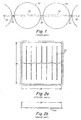
- One type of conventional inflatable device includes a plurality of seam connected parallel tubes, each tube being an inflatable bladder, as illustrated in Figure 1.
- This conventional inflatable device may be fabricated by sealing one layer of air-impervious film directly to another with a number of parallel seams 30, forming a plurality of parallel tubes 32.
- This type of structure commonly used for inflatable rafts, is easily constructed and inexpensive, but has some limitations. In particular, this type of structure may often suffer from dimensional instability.
- the inflated tubes 32 are less wide than deflated tubes 34.
- the conventional inflatable device is shown in a deflated condition.
- the bladder When empty of air the bladder is generally flat, having a length 36 and a width 38, as shown in Figures 2a and 2b. When inflated, the length and width of the bladder begin to shrink as the two layers of film separate. Referring to Figures 3a and 3b, it can be seen that the width 40 of the inflated bladder is significantly smaller than the width 38 of the empty bladder, while the change in length (36 to 41) of the bladder during inflation is negligible. Thus, the ratio of the length of the width of the device does not remain constant when the bladder is inflated. This dimensional instability of the conventional structures often limits the utility of the devices as cushions. The utility of the conventional structure as a cushioning surface is further limited to its irregular surface which provides uneven cushioning.
- the present invention is characterised in that the shape defining member combines with the inflatable bladder to control the distance between the sections such that the overall shape of the inflatable bladder in an inflated condition and in combination with the shape defining member is substantially different from an inflated shape of the inflatable bladder alone.
- the at least one shape defining member is flexible, although in an alternative embodiment, the at least one shape defining member is rigid and may comprise a rod or a bar.
- the at least one shape defining member is coupled to the inflatable sections at at least three locations and the plurality of sections may be separated by a plurality of seams and preferably the at least one shape defining member is connected to at least two of the seams and conveniently is coupled to the inflatable sections through the at least two seams.
- the at least one shape defining member is connected to at least three of the seams.
- the at least one shape defining member comprises a planar membrane.
- the planar membrane has a width that is substantially the same as the width of the inflatable bladder structure or alternately, the planar membrane substantially overspreads a surface of the inflatable bladder structure.
- the planar membrane is disposed on a first side of the inflatable bladder structure and the inflatable bladder structure may further comprise a second membrane disposed on a second side of the inflatable bladder structure.
- the planar membrane wraps around the plurality of fluidly interconnected inflatable sections.
- the at least one shape defining member is connected to the inflatable sections at a first location and at a second location on the inflatable bladder structure and the length of the shape defining member between the first location and the second location is less than the distance between the first location and the second location on the inflatable bladder structure that would exist in the absence of the shape defining member.
- the at least one shape defining member comprises a plurality of shape defining members.
- each of the plurality of sections is configured as a tube and preferably, each tube is disposed such that it is parallel to the other tubes.
- the tubes may have a length and a width and the lengths of the shape defining members may be disposed to extend substantially in the direction of the widths of the tubes.
- the inflatable bladder structure comprises two impermeable layers, the two layers being configured to form the plurality of fluidly interconnected inflatable sections, the layers preferably being sealed at an outer perimeter, and/or may be sealed at an edge.
- the layers are sealed at intervals, the seals forming a plurality of seams that at least partially separate the plurality of inflatable sections.
- the seams have a length less than the length of the inflatable bladder structure whereby the plurality of inflatable sections are fluidly interconnected.
- the at least one shape defining member is adapted to alter a separation of adjacent ones of the plurality of inflatable sections in the direction of the axis.
- the shape defining membrane may either attach to the inflatable bladder by means of fasteners, and may at least partially encompass the inflatable bladder.
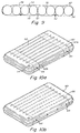
- the configurable inflatable device may include a covering layer that at least partially encompasses the inflatable bladder.
- the configurable inflatable device may include a self-sealing valve to allow for inflation and deflation of the inflatable bladder and for adjustment of a level of inflation of the inflatable bladder.
- the inflatable bladder may include two layers of film that are sealed at a perimeter and sealed internally at regular intervals by a plurality of internal seams.
- the plurality of internal seams may be substantially shorter than an overall length of the inflatable bladder in a direction of orientation of the plurality of internal seams.
- the membrane may further include a plurality of flexible strips that are attached to at least some of the plurality of internal seams.
- the membrane may include a plurality of rigid bars. The membrane may be attached to at least some of the plurality of internal seams by attachment devices.
- the inflatable bladder may have a first width when deflated, and the membrane may have a second width wherein the second width is substantially smaller than the first width.
- the configurable inflatable device may further include a covering layer that at least partially surrounds the inflatable bladder.
- the covering layer may include a plurality of bands that fit around the inflatable bladder.
- the covering layer may be attached to at least one of the inflatable bladder and the membrane, or may have an envelope structure and substantially, completely surround the inflatable bladder.
- the covering layer may be quilted or padded or may include a comfort-enhancing fabric.
- the covering layer may also include a mesh material.
- the covering layer may be attached to at least one side of the inflatable bladder.
- the membrane may include an opening through which the inflatable bladder can be inserted into the membrane.
- the membrane may include at least one opening forming a sleeve and the inflatable bladder may be inserted within the sleeve.
- the configurable inflatable device may include a planar membrane and a covering layer that at least partially surrounds the at least one inflatable bladder, wherein the covering layer is attached to the planar membrane.
- the planar membrane may be, for example, substantially rectangular.
- the configurable inflatable device may further include a rigid member attached to the planar membrane.
- At least one of the covering layer and the planar membrane may also include attachment devices for attaching the covering layer to the planar membrane, wherein the attachment devices are also adapted for adjusting a length of the planar membrane.
- a method for configuring an inflatable bladder comprises combining a shape defining member with an inflatable bladder including at least two layers sealed at a perimeter and sealed at regular intervals by a plurality of seams to provide a plurality of sections so that the shape defining member is coupled to or in contact with at least some of the plurality of sections and inflating the bladder so that the distance between the sections is controlled by the shape defining member, the overall shape of the inflatable bladder in an inflated condition and in combination with the shape defining member being substantially different from an inflated shape of the inflatable bladder alone.
- the term “fluid” as used herein is meant to include all types of liquids and gases, for example, water or air, and other fluids, such as gels, that may be used to inflate the inflatable bladders of the invention.
- the term “planar” as used herein is meant to describe a structure, for example a membrane, that is substantially flat in one configuration, although it may not be completely flat and may have portions that protrude from the plane of the body of the structure, and may also have many other configurations in which it is not substantially flat.
- an inflatable bladder may be provided in combination with a material that has a more stable length to width ratio. Such a combination may result in an inflatable device that does not contract or expand along a length to width axis upon inflation and deflation and may additionally provide a more uniform and stable cushioning surface than prior art structures.
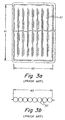
- a tube/mattress structure may include a plurality of interconnected tubes 42 attached to a membrane 44, which may be rigid or flexible, by means of attachment devices 52.
- the membrane may be a planar membrane.
- the planar membrane 44 may fix a width 46 of the tube/mattress structure at a value that may be somewhat less than its normal deflated width. In use, whether partially or fully inflated, attachment of the interconnected tubes 42 to the planar membrane 44 may add stability to the width dimension, predetermining the amount by which the width may expand or contract in accordance with the requirements of any particular application.
- the interconnected tubes 42 may be arranged substantially parallel to one another, as illustrated. However, it is to be appreciated that the interconnected tubes 42 may be arranged in a variety of other configurations.
- a tube/mattress structure may comprise one or more inflatable bladders formed from two layers of film, sealed at a perimeter 48 and sealed internally at regular, intervals by internal seams 50.
- the bladders Upon inflation, the bladders form tubes 42 of fluid having a generally circular cross-section, as illustrated.
- the internal seams 50 may be substantially shorter than an overall length of the bladder to allow generous fluid passage between chambers.
- the device may have alternate parallel seams 50, and may be attached to the planar membrane at controlled intervals by means of attachment devices 52.
- the inflatable bladder(s) may comprise a valve 54 that may be used to inflate and deflate the device.
- the valve 54 may be a self-sealing valve, as will be described in more detail below.
- the alternate seams 50 may force the bladders 42 to assume a compressed, corrugated configuration (zigzag end profile), as illustrated in FIG. 4a
- This structure may improve surface resiliency, providing depth and uniformity of surface which may be unavailable with conventional parallel tube structures, and may be dimensionally stable, retaining the same length to width ratio whether inflated or deflated. Because it is dimensionally stable, the tube/mattress structure may be sized or shaped to accommodate a variety of applications which conventional parallel tube devices may not serve well due to their dimensional instability and irregular surface.
- the tube/mattress structure may further be provided with fasteners to enable it to be attached to a fixed surface such as, for example, a wall or chair, or any rigid member.
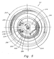
- a self sealing valve 54 may include a diaphragm 200 positioned within a valve housing 202 by a movable hanger arm 204 which suspends the diaphragm from a mounting point 206 in the center of an air inlet 208.
- the hanger arm 204 is a rotating diaphragm hanger that is removably contained within the air inlet 208 of the valve housing 202, with one end secured adjacent to an inner wall 210 of the air inlet 208.
- a point of attachment of the one end of the hanger arm 204 to the inner wall 210 is configured to allow the hanger arm 204 to pivot downward into the valve housing 202, a motion which unseats the diaphragm 200 from a valve seat 212, in a closed position, and opens an airpath, to an open position, into the bladder of the surface comfort layer device to allow for both inflation and deflation of the inflatable bladders of the tube structure.
- the hanger arm 204 flares outward towards the inner wall 210 of the air inlet 208 creating a "paddle" surface 214 which overspreads much of the air inlet 208.
- the paddle surface 214 of the hanger arm 204 provides stability to the flexible diaphragm 200 as it rotates with the hanger arm 204 from the closed position to the open position.
- the expanded paddle surface 214 of the hanger arm 204 also enhances manipulation of the hanger arm 204 by, for example, a fingertip of a user to, for example, control a firmness of the inflatable bladder.
- the paddle surface 214 projects outward to a point 216, extending the length of the hanger arm 204. This projection bears upon the flexible diaphragm 200, thereby preventing it from flexing upward when the hanger arm 204 is pressed downward for firmness control or deflation.
- the hanger arm 204 may be secured within the air inlet 208 with a pair of hinge pins 218.
- the contoured section 220 interfaces with a contoured end 222 of projecting tabs 205 to provide a plurality of distinct interaction possibilities.
- the tube/mattress structure may be further adjustable and configurable by controlling tho degree of inflation of the inflatable bladders using the self-sealing valve 54.
- the firmness (degree of inflation) of the inflatable bladder may be controlled, which may in turn partially control the shape of the tube/mattress structure.
- the utility of the tubs/mattress structure, and other embodiments of the invention, may vary depending on the level of inflation.
- a planar membrane 44 may include a plurality of strips 56 of flexible material running perpendicular to the direction of the tubes 42.
- the strips 56 may be attached at alternative parallel seams 50 by means of attachment devices 52.
- the strips 56 may be, for example, tubes, rods, bars, etc. made of a rigid material and may be combined with the inflatable bladder 42 to provide rigidity to the structure.
- the tube/mattress structure may incorporate an attached planar membrane as described above on both opposing surfaces of the structure. This may add further rigidity and dimensional stability to the structure.
- An inflatable device comprising an inflatable bladder including at least two layers sealed at a perimeter and sealed at regular intervals by a plurality of seams to provide a plurality of sections, at least one shape defining member coupled to or in contact with at least some of the plurality of sections to alter the separation between the sections when the bladder is inflated, characterised in that the shape defining member combines with the inflatable bladder to alter the separation between the sections such that the overall shape of the inflatable bladder in an inflated condition and in combination with the shape defining member is substantially different from an inflated shape of the inflatable bladder alone.
- the inflatable bladder may be provided in a variety of shapes and sizes and may be combined with a variety of attachable membranes, rigid members and covering layers.
- many configurable inflatable devices may be obtained, which may have structures different from the structure of the inflatable bladder alone.
- the membranes or covering layers in different ways, as discussed, a variety of configurable structures may be obtained using a single inflatable bladder.
- the inflatable structure may be further adjustable and configurable by controlling the degree of inflation of the inflatable bladder. For example, for inflatable bladders equipped with a self-sealing valve, as discussed above, by manipulating the hanger arm of the valve, the firmness (degree of inflation) of the inflatable bladder may be controlled which may in turn partially control the shape and utility of the inflatable structure.
- the above description is therefore by way of example only, and includes any modifications and improvements that may be apparent to one skilled in the art.
- the scope of the invention should be determined from proper construction of the appended claims and their equivalents.
Landscapes
- Health & Medical Sciences (AREA)
- Pulmonology (AREA)
- Otolaryngology (AREA)
- General Health & Medical Sciences (AREA)
- Mechanical Engineering (AREA)
- Ocean & Marine Engineering (AREA)
- Chemical & Material Sciences (AREA)
- Combustion & Propulsion (AREA)
- Engineering & Computer Science (AREA)
- Mattresses And Other Support Structures For Chairs And Beds (AREA)
- Prostheses (AREA)
- Professional, Industrial, Or Sporting Protective Garments (AREA)
- Invalid Beds And Related Equipment (AREA)
- Casting Or Compression Moulding Of Plastics Or The Like (AREA)
Abstract
Description
- The present invention relates to an inflatable device comprising an inflatable bladder including at least two layers sealed at a perimeter and sealed at regular intervals by a plurality of seams to provide a plurality of sections, at least one shape defining member coupled to or in contact with at least some of the plurality of sections so that when the bladder is inflated the distance between the sections is controlled by the shape defining member. Such an inflatable device is known from GB 903557.
- Further examples of inflatable support devices are disclosed in US 54743G1, US 3829918 and US 5970545. One type of conventional inflatable device includes a plurality of seam connected parallel tubes, each tube being an inflatable bladder, as illustrated in Figure 1. This conventional inflatable device may be fabricated by sealing one layer of air-impervious film directly to another with a number of
parallel seams 30, forming a plurality ofparallel tubes 32. This type of structure, commonly used for inflatable rafts, is easily constructed and inexpensive, but has some limitations. In particular, this type of structure may often suffer from dimensional instability. As illustrated in Figure 1, when inflated, the inflatedtubes 32 are less wide than deflatedtubes 34. Referring to Figures 2a and 2b, the conventional inflatable device is shown in a deflated condition. When empty of air the bladder is generally flat, having alength 36 and awidth 38, as shown in Figures 2a and 2b. When inflated, the length and width of the bladder begin to shrink as the two layers of film separate. Referring to Figures 3a and 3b, it can be seen that thewidth 40 of the inflated bladder is significantly smaller than thewidth 38 of the empty bladder, while the change in length (36 to 41) of the bladder during inflation is negligible. Thus, the ratio of the length of the width of the device does not remain constant when the bladder is inflated. This dimensional instability of the conventional structures often limits the utility of the devices as cushions. The utility of the conventional structure as a cushioning surface is further limited to its irregular surface which provides uneven cushioning. - The present invention is characterised in that the shape defining member combines with the inflatable bladder to control the distance between the sections such that the overall shape of the inflatable bladder in an inflated condition and in combination with the shape defining member is substantially different from an inflated shape of the inflatable bladder alone.
- In a preferred embodiment, the at least one shape defining member is flexible, although in an alternative embodiment, the at least one shape defining member is rigid and may comprise a rod or a bar.
- Preferably, the at least one shape defining member is coupled to the inflatable sections at at least three locations and the plurality of sections may be separated by a plurality of seams and preferably the at least one shape defining member is connected to at least two of the seams and conveniently is coupled to the inflatable sections through the at least two seams. Advantageously, the at least one shape defining member is connected to at least three of the seams.
- In a preferred embodiment, the at least one shape defining member comprises a planar membrane. Preferably, the planar membrane has a width that is substantially the same as the width of the inflatable bladder structure or alternately, the planar membrane substantially overspreads a surface of the inflatable bladder structure. Preferably; the planar membrane is disposed on a first side of the inflatable bladder structure and the inflatable bladder structure may further comprise a second membrane disposed on a second side of the inflatable bladder structure. Conveniently, the planar membrane wraps around the plurality of fluidly interconnected inflatable sections.
- In a preferred embodiment, the at least one shape defining member is connected to the inflatable sections at a first location and at a second location on the inflatable bladder structure and the length of the shape defining member between the first location and the second location is less than the distance between the first location and the second location on the inflatable bladder structure that would exist in the absence of the shape defining member. Preferably, the at least one shape defining member comprises a plurality of shape defining members.
- In a preferred embodiment, each of the plurality of sections is configured as a tube and preferably, each tube is disposed such that it is parallel to the other tubes. The tubes may have a length and a width and the lengths of the shape defining members may be disposed to extend substantially in the direction of the widths of the tubes.
- Advantageously, the inflatable bladder structure comprises two impermeable layers, the two layers being configured to form the plurality of fluidly interconnected inflatable sections, the layers preferably being sealed at an outer perimeter, and/or may be sealed at an edge. In a preferred embodiment, the layers are sealed at intervals, the seals forming a plurality of seams that at least partially separate the plurality of inflatable sections.
- Preferably, the seams have a length less than the length of the inflatable bladder structure whereby the plurality of inflatable sections are fluidly interconnected.
- Advantageously, the at least one shape defining member is adapted to alter a separation of adjacent ones of the plurality of inflatable sections in the direction of the axis.
- In one example, the shape defining membrane may either attach to the inflatable bladder by means of fasteners, and may at least partially encompass the inflatable bladder. In another example, the configurable inflatable device may include a covering layer that at least partially encompasses the inflatable bladder. In addition, the configurable inflatable device may include a self-sealing valve to allow for inflation and deflation of the inflatable bladder and for adjustment of a level of inflation of the inflatable bladder.
- In one example, the inflatable bladder may include two layers of film that are sealed at a perimeter and sealed internally at regular intervals by a plurality of internal seams. The plurality of internal seams may be substantially shorter than an overall length of the inflatable bladder in a direction of orientation of the plurality of internal seams. The membrane may further include a plurality of flexible strips that are attached to at least some of the plurality of internal seams. In another example, the membrane may include a plurality of rigid bars. The membrane may be attached to at least some of the plurality of internal seams by attachment devices.
- According to another embodiment of the configurable inflatable device, the inflatable bladder may have a first width when deflated, and the membrane may have a second width wherein the second width is substantially smaller than the first width. The configurable inflatable device may further include a covering layer that at least partially surrounds the inflatable bladder. For example, the covering layer may include a plurality of bands that fit around the inflatable bladder. Alternatively, the covering layer may be attached to at least one of the inflatable bladder and the membrane, or may have an envelope structure and substantially, completely surround the inflatable bladder. The covering layer may be quilted or padded or may include a comfort-enhancing fabric. The covering layer may also include a mesh material. In yet another example, the covering layer may be attached to at least one side of the inflatable bladder.
- In another example, the membrane may include an opening through which the inflatable bladder can be inserted into the membrane. For example, the membrane may include at least one opening forming a sleeve and the inflatable bladder may be inserted within the sleeve.
- According to another example, the configurable inflatable device may include a planar membrane and a covering layer that at least partially surrounds the at least one inflatable bladder, wherein the covering layer is attached to the planar membrane. The planar membrane may be, for example, substantially rectangular. The configurable inflatable device may further include a rigid member attached to the planar membrane. At least one of the covering layer and the planar membrane may also include attachment devices for attaching the covering layer to the planar membrane, wherein the attachment devices are also adapted for adjusting a length of the planar membrane.
- According to yet another embodiment of the invention, a method for configuring an inflatable bladder is provided and comprises combining a shape defining member with an inflatable bladder including at least two layers sealed at a perimeter and sealed at regular intervals by a plurality of seams to provide a plurality of sections so that the shape defining member is coupled to or in contact with at least some of the plurality of sections and inflating the bladder so that the distance between the sections is controlled by the shape defining member, the overall shape of the inflatable bladder in an inflated condition and in combination with the shape defining member being substantially different from an inflated shape of the inflatable bladder alone.
- Embodiments of the present invention will now be described, by way of example only, with reference to Figures 4a to 10d of the accompanying drawings, in which:
- Figure 1 is a cross-sectional view of a conventional inflatable device;
- Figure 2a is a plan view of a conventional inflatable device when not inflated;
- Figure 2b is a cross-sectional view of the conventional inflatable device of Figure 2a;
- Figure 3a is a plan view of the conventional inflatable device of Figure 1a when inflated;
- Figure 3b is a cross-sectional view of the conventional inflatable device of Figure 3a when inflated;
- Figure 4a is a cross-sectional view of an example of one embodiment of an inflatable device according to aspects of the invention;
- Figure 4b is an enlarged view of a portion of the inflatable device of Figure 4a;
- Figure 4c is a plan view of the inflatable device of Figure 4a;
- Figure 5 is a top plan view of an example of a self-sealing valve that may be used with the inflatable bladders of the invention;
- Figures 6-8 are cross-sectional views of the self-sealing valve of Figure 5;
- Figure 9 is a cross-sectional view of one example of an inflatable device according to aspects of the invention;
- Figures 10a-10d are perspective views of an inflatable device according to the invention including a covering layer.
- Structures for inflatable support devices comprising rigid members, membranes and fasteners that may be combined in a variety of configurations to add utility to the basic structure of an inflatable bladder are disclosed herein. Also described are a variety of applications in which an inflatable bladder is used in combination with other members to provide support or comfort to persons or objects on land or in water. It is to be understood that the invention is not limited in its application to the details of construction and the arrangement of components set forth in the following description or illustrated in the drawings. Other embodiments and manners of carrying out the invention are possible. Also, it is to be understood that the phraseology and terminology used herein is for the purpose of description and should not be regarded as limiting. The use of "including", "comprising" or "having" and variations thereof is meant to encompass the items listed thereafter and equivalents thereof as well as additional items. Furthermore, the term "fluid" as used herein is meant to include all types of liquids and gases, for example, water or air, and other fluids, such as gels, that may be used to inflate the inflatable bladders of the invention. In addition, the term "planar" as used herein is meant to describe a structure, for example a membrane, that is substantially flat in one configuration, although it may not be completely flat and may have portions that protrude from the plane of the body of the structure, and may also have many other configurations in which it is not substantially flat.
- Referring to Figures 4a-c, there is illustrated an example of a parallel tube structure that overcomes the limitations of the prior art. According to one embodiment, an inflatable bladder may be provided in combination with a material that has a more stable length to width ratio. Such a combination may result in an inflatable device that does not contract or expand along a length to width axis upon inflation and deflation and may additionally provide a more uniform and stable cushioning surface than prior art structures. Referring to FIG. 4a, a tube/mattress structure may include a plurality of
interconnected tubes 42 attached to amembrane 44, which may be rigid or flexible, by means ofattachment devices 52. According to one embodiment, the membrane may be a planar membrane. Theplanar membrane 44 may fix a width 46 of the tube/mattress structure at a value that may be somewhat less than its normal deflated width. In use, whether partially or fully inflated, attachment of theinterconnected tubes 42 to theplanar membrane 44 may add stability to the width dimension, predetermining the amount by which the width may expand or contract in accordance with the requirements of any particular application. In one example, theinterconnected tubes 42 may be arranged substantially parallel to one another, as illustrated. However, it is to be appreciated that theinterconnected tubes 42 may be arranged in a variety of other configurations. - According to one example, illustrated in FIGS. 4a-c, a tube/mattress structure may comprise one or more inflatable bladders formed from two layers of film, sealed at a
perimeter 48 and sealed internally at regular, intervals byinternal seams 50. Upon inflation, the bladders formtubes 42 of fluid having a generally circular cross-section, as illustrated. Theinternal seams 50 may be substantially shorter than an overall length of the bladder to allow generous fluid passage between chambers. In one example, the device may have alternateparallel seams 50, and may be attached to the planar membrane at controlled intervals by means ofattachment devices 52. The inflatable bladder(s) may comprise avalve 54 that may be used to inflate and deflate the device. According to one example, thevalve 54 may be a self-sealing valve, as will be described in more detail below. Upon inflation, thealternate seams 50 may force thebladders 42 to assume a compressed, corrugated configuration (zigzag end profile), as illustrated in FIG. 4a This structure may improve surface resiliency, providing depth and uniformity of surface which may be unavailable with conventional parallel tube structures, and may be dimensionally stable, retaining the same length to width ratio whether inflated or deflated. Because it is dimensionally stable, the tube/mattress structure may be sized or shaped to accommodate a variety of applications which conventional parallel tube devices may not serve well due to their dimensional instability and irregular surface. The tube/mattress structure may further be provided with fasteners to enable it to be attached to a fixed surface such as, for example, a wall or chair, or any rigid member. - Referring to FIGS. 5-8, there is illustrated one embodiment of a self-sealing
valve 54 that may be used with the tube structure described above. In this embodiment, aself sealing valve 54 may include adiaphragm 200 positioned within avalve housing 202 by amovable hanger arm 204 which suspends the diaphragm from a mountingpoint 206 in the center of anair inlet 208. Thehanger arm 204 is a rotating diaphragm hanger that is removably contained within theair inlet 208 of thevalve housing 202, with one end secured adjacent to aninner wall 210 of theair inlet 208. A point of attachment of the one end of thehanger arm 204 to theinner wall 210 is configured to allow thehanger arm 204 to pivot downward into thevalve housing 202, a motion which unseats thediaphragm 200 from avalve seat 212, in a closed position, and opens an airpath, to an open position, into the bladder of the surface comfort layer device to allow for both inflation and deflation of the inflatable bladders of the tube structure. - According to one example, the
hanger arm 204 flares outward towards theinner wall 210 of theair inlet 208 creating a "paddle"surface 214 which overspreads much of theair inlet 208. Thepaddle surface 214 of thehanger arm 204 provides stability to theflexible diaphragm 200 as it rotates with thehanger arm 204 from the closed position to the open position. The expandedpaddle surface 214 of thehanger arm 204 also enhances manipulation of thehanger arm 204 by, for example, a fingertip of a user to, for example, control a firmness of the inflatable bladder. Thepaddle surface 214 projects outward to apoint 216, extending the length of thehanger arm 204. This projection bears upon theflexible diaphragm 200, thereby preventing it from flexing upward when thehanger arm 204 is pressed downward for firmness control or deflation. - The
hanger arm 204 may be secured within theair inlet 208 with a pair of hinge pins 218. In one example, there is acontoured section 220 between the hinge pins 218 of the inner wall of at least one of the brackets and theinner wall 210 of theair inlet 208. The contouredsection 220 interfaces with acontoured end 222 of projectingtabs 205 to provide a plurality of distinct interaction possibilities. A first possibility exists when surfaces 224 on the projectingtabs 205 bear onsurfaces 226 of the inner wall, restricting rotation of the arm above a horizontal position, thereby securing the valve diaphragm in a substantially closed position. - A second possibility exists when a beveled surface 223 on the projecting
tabs 205 bear oncounter-beveled surfaces 230 on the wall An incline of thesecounter-beveled surfaces 230 cause the projecting tabs to increasingly compress inward as thehanger arm 204 is pressed downward into thevalve housing 202. This may occur both during inflation (by air pressure) and deflation (by manual deflection oftho hanger arm to unseat the valve from the valve seat). The compression of the projecting tabs also results In a counter action, so that, with removal of the downward pressuro the tabs spring back to their original position and forces thehanger arm 204 anddiaphragm 200 to return to tho closed position. When thehanger arm 204 is depressed fully, the projecting tabs rotate slightly beyond thebeveled surface 230 and lock the rotating arm in a locked open position. This locked open position maximizes airflow through the valve housing and will, under certain conditions improve efficiency of both inflation and deflation. Those and other embodiments of the self-sealingvalve 54 are described in more detail In U.S. Patent No. 6,237,621. - It is to be appreciated that the tube/mattress structure may be further adjustable and configurable by controlling tho degree of inflation of the inflatable bladders using the self-sealing
valve 54. As discussed above, by manipulating the hanger arm of the valve, the firmness (degree of inflation) of the inflatable bladder may be controlled, which may in turn partially control the shape of the tube/mattress structure. The utility of the tubs/mattress structure, and other embodiments of the invention, may vary depending on the level of inflation. - For portable applications, or other applications where maximum collapsibility may be desirable, flexibility of the
planar membrane 44 may be important. Theplanar membrane 44 does not have to be solid or closed. For example, referring to FIG. 9, which illustrates another example of a tube/mattress structure, a planar membrane may include a plurality ofstrips 56 of flexible material running perpendicular to the direction of thetubes 42. Thestrips 56 may be attached at alternativeparallel seams 50 by means ofattachment devices 52. Alternatively, instead of being made of a flexible material, thestrips 56 may be, for example, tubes, rods, bars, etc. made of a rigid material and may be combined with theinflatable bladder 42 to provide rigidity to the structure. According to another example, the tube/mattress structure may incorporate an attached planar membrane as described above on both opposing surfaces of the structure. This may add further rigidity and dimensional stability to the structure. - An inflatable device comprising an inflatable bladder including at least two layers sealed at a perimeter and sealed at regular intervals by a plurality of seams to provide a plurality of sections, at least one shape defining member coupled to or in contact with at least some of the plurality of sections to alter the separation between the sections when the bladder is inflated, characterised in that the shape defining member combines with the inflatable bladder to alter the separation between the sections such that the overall shape of the inflatable bladder in an inflated condition and in combination with the shape defining member is substantially different from an inflated shape of the inflatable bladder alone.
- It is to be appreciated that the inflatable bladder may be provided in a variety of shapes and sizes and may be combined with a variety of attachable membranes, rigid members and covering layers. Thereby, many configurable inflatable devices may be obtained, which may have structures different from the structure of the inflatable bladder alone. Also, by attaching the membranes or covering layers in different ways, as discussed, a variety of configurable structures may be obtained using a single inflatable bladder. Furthermore, the inflatable structure may be further adjustable and configurable by controlling the degree of inflation of the inflatable bladder. For example, for inflatable bladders equipped with a self-sealing valve, as discussed above, by manipulating the hanger arm of the valve, the firmness (degree of inflation) of the inflatable bladder may be controlled which may in turn partially control the shape and utility of the inflatable structure. The above description is therefore by way of example only, and includes any modifications and improvements that may be apparent to one skilled in the art. The scope of the invention should be determined from proper construction of the appended claims and their equivalents.
Claims (28)
- An inflatable device comprising an inflatable bladder including at least two layers sealed at a perimeter and sealed at regular intervals by a plurality of seams to provide a plurality of sections, at least one shape defining member coupled to or in contact with at least some of the plurality of sections so that when the bladder is inflated the distance between the sections is controlled by the shape defining member characterised in that the shape defining member combines with the inflatable bladder to control the distance between the sections such that the overall shape of the inflatable bladder in an inflated condition and in combination with the shape defining member is substantially different from an inflated shape of the inflatable bladder alone.
- The inflatable device as claimed in claim 1 wherein the at least one shape defining member includes at least one fastener disposed on at least one of the inflatable bladder and the shape defining member.
- The inflatable device as claimed in claim 2 wherein the at least one fastener includes a first fastener disposed on the shape defining member for attaching the shape defining member to the inflatable bladder.
- The inflatable device as claimed in claim 3 wherein the at least one fastener includes a second fastener disposed on the inflatable bladder and adapted to mate with the first fastener so as to attach the at least one shape defining member to the inflatable bladder.
- The inflatable device as claimed in any one of claims 1-4 wherein the shape defining member at least partially surrounds the inflatable bladder.
- The inflatable device as claimed in any one of claims 1-5 wherein the inflatable bladder includes a self-sealing valve.
- The inflatable device as claimed in any preceding claim wherein the plurality of seams are substantially shorter than an overall length of the inflatable bladder in a direction of orientation of the plurality.
- The inflatable device as claimed in any preceding claim wherein the shape defining member includes at least one flexible strip that is attached to at least one of the plurality of internal seams.
- The inflatable device as claimed in any preceding claim wherein the shape defining member includes at least one rigid bar.
- The inflatable device as claimed in any preceding claim wherein the shape defining member is attached to at least one of the plurality of seams by an attachment device.
- The inflatable device as claimed in any preceding claim wherein the shape defining member is flexible.
- The inflatable device as claimed in any of claims 1-10 wherein the shape defining member includes a rigid member.
- The inflatable device as claimed in claim 10 wherein the inflatable bladder has a first width when deflated, the shape defining member has a second width and wherein the second width is substantially smaller than the first width.
- The inflatable device as claimed in claim 13 further including a covering layer that at least partially surrounds the inflatable bladder.
- The inflatable device as claimed in claim 14 wherein the covering layer includes at least one band that fits around the inflatable bladder.
- The inflatable device as claimed in claim 14 wherein the covering layer includes a plurality of bands that fit around the inflatable bladder.
- The inflatable device as claimed in any of claims 14 to 16 wherein the covering layer is attached to at least one of the inflatable bladder and the shape defining member.
- The inflatable device as claimed in any of claims 14 to 17 wherein the covering layer is quilted.
- The inflatable device as claimed in any of claims 14 to 18 wherein the covering layer has an envelope structure and substantially completely surrounds the inflatable bladder.
- The inflatable device as claimed in any one of claims 1-13 wherein the shape defining member includes a planar membrane and a covering layer that at least partially surrounds the at least one inflatable bladder and wherein the covering layer is attached to the planar membrane.
- The inflatable device as claimed in claim 20 wherein the planar membrane is substantially rectangular.
- The inflatable device as claimed in claim 20 further including a rigid member attached to the planar membrane.
- The inflatable device as claimed in claim 20 wherein the inflatable bladder is substantially contained within the covering layer.
- The inflatable device as claimed in claim 20 wherein the at least one of the covering layer and the planar membrane include attachment devices for attaching the covering layer to the planar membrane, and wherein the attachment devices are also adapted for adjusting a length of the planar membrane.
- The inflatable device as claimed in claim 1 further comprising a comfort layer that is a resilient material.
- The inflatable device as claimed in claim 25 wherein the comfort layer comprises a foam.
- The inflatable device as claimed in claim 1 wherein the shape defining member includes a plurality of membranes.
- A method of configuring an inflatable body comprising combining a shape defining member with an inflatable bladder including at least two layers sealed at a perimeter and sealed at regular intervals by a plurality of seams to provide a plurality of sections so that the shape defining member is coupled to or in contact with at least some of the plurality of sections and inflating the bladder so that the distance between the sections is controlled by the shape defining member, the overall shape of the inflatable bladder in an inflated condition and in combination with the shape defining member is substantially different from an inflated shape of the inflatable bladder alone.
Priority Applications (1)
| Application Number | Priority Date | Filing Date | Title |
|---|---|---|---|
| EP06114421A EP1688067B1 (en) | 2001-07-10 | 2002-07-10 | Configurable inflatable support devices |
Applications Claiming Priority (5)
| Application Number | Priority Date | Filing Date | Title |
|---|---|---|---|
| US30427401P | 2001-07-10 | 2001-07-10 | |
| US304274P | 2001-07-10 | ||
| US37440302P | 2002-04-22 | 2002-04-22 | |
| US374403P | 2002-04-22 | ||
| PCT/US2002/021756 WO2003005861A1 (en) | 2001-07-10 | 2002-07-10 | Configurable inflatable support devices |
Related Child Applications (1)
| Application Number | Title | Priority Date | Filing Date |
|---|---|---|---|
| EP06114421A Division EP1688067B1 (en) | 2001-07-10 | 2002-07-10 | Configurable inflatable support devices |
Publications (2)
| Publication Number | Publication Date |
|---|---|
| EP1404196A1 EP1404196A1 (en) | 2004-04-07 |
| EP1404196B1 true EP1404196B1 (en) | 2006-05-24 |
Family
ID=26973924
Family Applications (2)
| Application Number | Title | Priority Date | Filing Date |
|---|---|---|---|
| EP02784901A Expired - Lifetime EP1404196B1 (en) | 2001-07-10 | 2002-07-10 | Configurable inflatable support devices |
| EP06114421A Expired - Lifetime EP1688067B1 (en) | 2001-07-10 | 2002-07-10 | Configurable inflatable support devices |
Family Applications After (1)
| Application Number | Title | Priority Date | Filing Date |
|---|---|---|---|
| EP06114421A Expired - Lifetime EP1688067B1 (en) | 2001-07-10 | 2002-07-10 | Configurable inflatable support devices |
Country Status (8)
| Country | Link |
|---|---|
| US (3) | US7328472B2 (en) |
| EP (2) | EP1404196B1 (en) |
| JP (1) | JP4540336B2 (en) |
| CN (1) | CN100502730C (en) |
| AT (1) | ATE326884T1 (en) |
| CA (2) | CA2744867C (en) |
| DE (2) | DE60229797D1 (en) |
| WO (1) | WO2003005861A1 (en) |
Families Citing this family (78)
| Publication number | Priority date | Publication date | Assignee | Title |
|---|---|---|---|---|
| US7025576B2 (en) | 2001-03-30 | 2006-04-11 | Chaffee Robert B | Pump with axial conduit |
| CA2408536C (en) * | 2000-05-17 | 2008-09-30 | Robert B. Chaffee | Inflatable device with recessed fluid controller and modified adjustment device |
| RU2271129C2 (en) * | 2001-03-30 | 2006-03-10 | Роберт Б. ШАФФЕ | Inflatable apparatus with deepened fluid control means and control panel |
| WO2003005861A1 (en) * | 2001-07-10 | 2003-01-23 | Robert Chaffee | Configurable inflatable support devices |
| US7160235B2 (en) * | 2001-07-20 | 2007-01-09 | Mcnally Lynda Jeanne | Passive exercise apparatus |
| US6701559B2 (en) * | 2001-08-01 | 2004-03-09 | Aero Products International, Inc. | Increased height inflatable support system |
| US7478448B2 (en) * | 2001-08-01 | 2009-01-20 | Aero Products International, Inc. | Inflatable reinforcing chamber |
| US7000276B2 (en) * | 2002-04-11 | 2006-02-21 | Chaffee Robert B | Body support surface comfort device |
| AU2003230889A1 (en) | 2002-04-11 | 2003-10-27 | Robert B. Chaffee | Body support surface comfort device |
| WO2003093709A1 (en) | 2002-05-03 | 2003-11-13 | Chaffee Robert B | Self-sealing valve with electromechanical device for actuating the valve |
| WO2004006726A1 (en) * | 2002-07-17 | 2004-01-22 | Aero Products International, Inc. | Inflatable support system |
| MXPA05005493A (en) | 2002-11-18 | 2005-09-08 | B Chaffee Robert | Inflatable device. |
| GB0312164D0 (en) * | 2003-05-28 | 2003-07-02 | Arjo Med Aktiebolag Ltd | Lifting slings |
| US20050187085A1 (en) * | 2004-02-24 | 2005-08-25 | Webb Nicholas J. | Inflatable abdominal exercise apparatus |
| US20050250630A1 (en) * | 2004-05-10 | 2005-11-10 | Webb Nicholas J | Inflatable abdominal exercise apparatus |
| US20050250629A1 (en) * | 2004-05-10 | 2005-11-10 | Webb Nicholas J | Inflatable abdominal exercise apparatus |
| US20100211143A1 (en) * | 2005-01-10 | 2010-08-19 | Nan Chih Lu | Pressure Adjustable Structure for Ice Compress |
| US20070033739A1 (en) * | 2005-08-12 | 2007-02-15 | Austen Timothy F | Inflatable support system having thermoplastic polyurethane construction |
| US7299513B1 (en) * | 2005-08-29 | 2007-11-27 | F.O. Berg Company | Bladder support system |
| US20070056114A1 (en) * | 2005-09-09 | 2007-03-15 | Corey Lewison | Multi-zone coil construction airbed |
| US8413278B2 (en) | 2006-04-04 | 2013-04-09 | Robert B. Chaffee | Method and apparatus for monitoring and controlling pressure in an inflatable device |
| CA2648001C (en) * | 2006-04-04 | 2014-12-09 | Robert B. Chaffee | Method and apparatus for monitoring and controlling pressure in an inflatable device |
| US8635999B2 (en) * | 2006-04-07 | 2014-01-28 | Richard C Rosene | Floating spa cover or adjustable size |
| EP2030532A1 (en) | 2007-08-31 | 2009-03-04 | Derin-Holzapfel & Co. Grundbesitz und Beteiligungs KG | Floating mattress with cushion |
| US20090287093A1 (en) * | 2008-05-15 | 2009-11-19 | Searete Llc, A Limited Liability Corporation Of The State Of Delaware | Circulatory monitoring systems and methods |
| US20090287120A1 (en) | 2007-12-18 | 2009-11-19 | Searete Llc, A Limited Liability Corporation Of The State Of Delaware | Circulatory monitoring systems and methods |
| US9717896B2 (en) | 2007-12-18 | 2017-08-01 | Gearbox, Llc | Treatment indications informed by a priori implant information |
| US8636670B2 (en) | 2008-05-13 | 2014-01-28 | The Invention Science Fund I, Llc | Circulatory monitoring systems and methods |
| US20090234317A1 (en) * | 2008-03-13 | 2009-09-17 | Navarro Lissa M | Flexible, flat pouch with port for mixing and delivering powder-liquid mixture |
| US9028448B2 (en) * | 2008-06-19 | 2015-05-12 | Covidien Lp | Access seal with interstitial channels |
| US8307788B2 (en) * | 2008-10-06 | 2012-11-13 | Jerry Swires | Chute inflatable |
| GB0919600D0 (en) * | 2009-11-10 | 2009-12-23 | Qvision Ltd | Changing mat |
| US8657565B2 (en) | 2010-04-22 | 2014-02-25 | The Coleman Company, Inc. | Pump with integrated deflation port |
| EP2575723B1 (en) | 2010-06-02 | 2014-12-31 | TouchSensor Technologies, LLC | Therapeutic support device allowing capillary blood flow |
| FR2962309B1 (en) * | 2010-07-12 | 2012-08-31 | Impex | INFLATABLE STRUCTURE WITH COVER |
| EP2624800B1 (en) | 2010-10-05 | 2017-02-22 | TouchSensor Technologies, LLC | Support surface overlay with selectively inflatable cells |
| US8595873B2 (en) | 2010-12-08 | 2013-12-03 | Hill-Rom Services, Inc. | Mattress deflation management |
| US8336143B2 (en) | 2011-04-29 | 2012-12-25 | Clayton Lemmer | Air mattress |
| US9314118B2 (en) * | 2011-07-19 | 2016-04-19 | Jiajing Usa, Inc. | Comfort customizable pillow |
| US8997637B2 (en) * | 2011-10-12 | 2015-04-07 | Elend S. LeBaron | Dual bladder system and method for treatment and reduction of microbial content in fluids by means of high pressure |
| WO2014076550A2 (en) * | 2012-11-16 | 2014-05-22 | Neil Pryde Limited | Inflatable structure |
| US10058190B1 (en) | 2012-12-05 | 2018-08-28 | Jiajing Usa, Inc. | Air-foam mattress component |
| US20140225405A1 (en) * | 2013-02-14 | 2014-08-14 | Paul Mella | Inflatable Cushion Seat, Back Support, and Method |
| US9250041B2 (en) * | 2013-09-26 | 2016-02-02 | Warwick Mills Inc. | Shapable armor for users |
| CN104000418A (en) | 2014-03-24 | 2014-08-27 | 先驱塑胶电子(惠州)有限公司 | Inflatable product, sofa combination, and inflatable sofa with cloth cover |
| CN104473498B (en) * | 2014-10-31 | 2018-07-06 | 先驱塑胶电子(惠州)有限公司 | A kind of backrest conjoined pneumatic bed |
| US10758442B2 (en) * | 2015-03-16 | 2020-09-01 | Fondazione Irccs Ca' Granda-Ospedale Maggiore Policlinico | Device for positioning a bedridden patient |
| USD849450S1 (en) * | 2016-01-13 | 2019-05-28 | Bestway Inflatables & Material Corp. | Inflatable bed |
| US11013344B2 (en) * | 2016-01-20 | 2021-05-25 | National Bedding Company, L.L.C. | Mattress and adjustable foundation selection system and process |
| EP3272643B1 (en) * | 2016-07-20 | 2021-11-10 | Airbus Operations GmbH | Aircraft or spacecraft passenger cabin partition |
| US11319073B2 (en) * | 2016-08-31 | 2022-05-03 | Michelle O'Doherty | Apparatus for creating a sleeping surface |
| CN206368786U (en) | 2016-12-08 | 2017-08-01 | 明达实业(厦门)有限公司 | The attachment structure of pump and aerated product |
| US11470982B2 (en) * | 2017-06-19 | 2022-10-18 | Mark Johannessen | Air mattress with tensioned cover |
| US10806279B2 (en) | 2017-10-13 | 2020-10-20 | Robert Berney | Pillow with adjustable sleeve for inflatable air bladder |
| USD913191S1 (en) * | 2018-03-05 | 2021-03-16 | Nautibuoy Marine Limited | Floating platform |
| USD913187S1 (en) * | 2018-03-05 | 2021-03-16 | Nautibuoy Marine Limited | Floating platform |
| USD900704S1 (en) * | 2018-03-05 | 2020-11-03 | Nautibuoy Marine Limited | Floating platform |
| USD913901S1 (en) * | 2018-03-05 | 2021-03-23 | Nautibuoy Marine Limited | Floating platform |
| USD913190S1 (en) * | 2018-03-05 | 2021-03-16 | Nautibuoy Marine Limited | Floating platform |
| USD913185S1 (en) * | 2018-03-05 | 2021-03-16 | Nautibuoy Marine Limited | Floating platform |
| USD913186S1 (en) * | 2018-03-05 | 2021-03-16 | Nautibuoy Marine Limited | Floating platform |
| USD913189S1 (en) * | 2018-03-05 | 2021-03-16 | Nautibuoy Marine Limited | Floating platform |
| USD900703S1 (en) * | 2018-03-05 | 2020-11-03 | Nautibuoy Marine Limited | Floating platform |
| USD900705S1 (en) * | 2018-03-05 | 2020-11-03 | Nautibuoy Marine Limited | Floating platform |
| USD900702S1 (en) * | 2018-03-05 | 2020-11-03 | Nautibuoy Marine Limited | Floating platform |
| USD913188S1 (en) * | 2018-03-05 | 2021-03-16 | Nautibuoy Marine Limited | Floating platform |
| WO2019178007A1 (en) * | 2018-03-12 | 2019-09-19 | Heberling Peter Stephen Ii | Insertable bladder system for inflatable boat repair |
| USD910338S1 (en) * | 2018-08-14 | 2021-02-16 | Shanghai Jilong Plastic Products Co., Ltd. | Airbed |
| USD901940S1 (en) * | 2018-09-28 | 2020-11-17 | Stryker Corporation | Patient support |
| USD977109S1 (en) | 2018-09-28 | 2023-01-31 | Stryker Corporation | Crib assembly for a patient support |
| USD852543S1 (en) | 2019-03-28 | 2019-07-02 | Lorne Jason Clute | Inflatable mattress with bumper |
| CN110203344A (en) * | 2019-06-19 | 2019-09-06 | 黄芳 | A kind of deep water buoyancy unit module and production method |
| US11484449B2 (en) | 2019-08-13 | 2022-11-01 | Stryker Corporation | Support apparatus for bariatric person |
| US11351923B2 (en) * | 2019-12-05 | 2022-06-07 | GM Global Technology Operations LLC | Masked fabrication inflatable devices |
| US10973345B1 (en) | 2020-03-13 | 2021-04-13 | Brian Thomas Kirk | Inflatable beach and camping pillow |
| US11564499B2 (en) * | 2020-07-20 | 2023-01-31 | Lear Corporation | Seat adjuster |
| USD968547S1 (en) | 2021-12-17 | 2022-11-01 | Bote, Llc | Inflatable dock |
| CN112891175B (en) * | 2021-01-25 | 2022-06-03 | 佛山市高尔顿家具有限公司 | Man-machine massage air bag mattress with lifting adjustable function |
Family Cites Families (322)
| Publication number | Priority date | Publication date | Assignee | Title |
|---|---|---|---|---|
| US3123336A (en) | 1964-03-03 | Diaphragm valves | ||
| US625114A (en) | 1899-05-16 | Inflation-valve | ||
| US388037A (en) * | 1887-07-23 | 1888-08-21 | Air mattress | |
| US633968A (en) * | 1899-06-22 | 1899-09-26 | Charles A Hunt | Mattress. |
| US679519A (en) | 1900-12-31 | 1901-07-30 | Lyman T Smith | Valve for pneumatic tires. |
| US691118A (en) * | 1901-02-14 | 1902-01-14 | Charles W Curlin | Inflatable article. |
| US1185684A (en) | 1905-02-03 | 1916-06-06 | Schrader S Son Inc | Valve for pneumatic pillows and other articles. |
| US827823A (en) | 1906-02-26 | 1906-08-07 | George L Starr | Fluid-pressure brake. |
| US847758A (en) | 1906-05-09 | 1907-03-19 | Clara C Frye | Surgical appliance. |
| US918391A (en) * | 1907-10-29 | 1909-04-13 | Charles Taarud | Pillow. |
| US934465A (en) * | 1908-02-12 | 1909-09-21 | White Company | Ventilated cushion. |
| US1282980A (en) * | 1917-05-24 | 1918-10-29 | Nicholas M Takach | Pneumatic mattress. |
| US1263599A (en) | 1917-12-08 | 1918-04-23 | Ashton Hamilton | Pneumatic-tire valve. |
| US1361453A (en) * | 1919-08-25 | 1920-12-07 | Hannah H Frey | Cushion |
| US1451136A (en) | 1921-08-10 | 1923-04-10 | Benjamin F Allnutt | Filling tube for liquid receptacles |
| US1576211A (en) * | 1925-05-15 | 1926-03-09 | Walter C O'kane | Mattress |
| US1944466A (en) * | 1931-01-07 | 1934-01-23 | Rubin Benjamin Charles | Pneumatic mattress |
| US2064695A (en) | 1935-06-11 | 1936-12-15 | Nathaniel L Foster | Air valve |
| US2028060A (en) * | 1935-09-07 | 1936-01-14 | Gilbert Eskell | Protector |
| US2112641A (en) | 1936-09-25 | 1938-03-29 | Aw Wheaton Brass Works | Safety vent valve |
| US2168774A (en) | 1938-07-08 | 1939-08-08 | Automatic Switch Co | Solenoid valve |
| US2288889A (en) | 1939-05-12 | 1942-07-07 | Francis J Costello | Valve |
| US2372218A (en) * | 1941-07-25 | 1945-03-27 | Frank G Manson | Pneumatic mattress |
| US2285324A (en) | 1941-11-12 | 1942-06-02 | Bennett Alexander Edgar | Check valve operator |
| US2456690A (en) | 1942-08-28 | 1948-12-21 | United Shoe Machinery Corp | Fluid-pressure-operated mechanism |
| US2369736A (en) * | 1942-12-29 | 1945-02-20 | Us Rubber Co | Pneumatic mattress |
| US2482198A (en) | 1944-09-05 | 1949-09-20 | Parker Appliance Co | Valve structure |
| US2459689A (en) | 1944-09-22 | 1949-01-18 | Bailey Meter Co | Fluid rate of flow measuring apparatus |
| US2415150A (en) * | 1945-06-08 | 1947-02-04 | Stein Michael Russell | Pneumatic mattress |
| US2434641A (en) * | 1946-02-20 | 1948-01-20 | Henry L Burns | Resilient seat cushion |
| US2604641A (en) * | 1947-02-11 | 1952-07-29 | Stanley F Reed | Inflatable mattress |
| US2575764A (en) | 1947-04-10 | 1951-11-20 | Hans G Morner | Air-filled upholstery and method of manufacture |
| US2614272A (en) | 1947-04-15 | 1952-10-21 | Morner Hans George | Upholstery unit |
| US2672628A (en) * | 1947-10-30 | 1954-03-23 | Abraham N Spanel | Utility device for infants |
| US2549597A (en) * | 1948-03-10 | 1951-04-17 | New York Rubber Corp | Inflatable mattress for cribs and the like |
| US2565406A (en) | 1948-07-08 | 1951-08-21 | Stennitt Thomas | Power-operable wood-splitting machine |
| US2767735A (en) | 1951-10-24 | 1956-10-23 | Dumont Aircraft Fitting Compan | Valve device |
| US2701579A (en) | 1952-01-02 | 1955-02-08 | Goodrich Co B F | Inflating valve for inflatable articles |
| US2741780A (en) * | 1953-03-31 | 1956-04-17 | Kimbrig Louis | Inflatable mattress core |
| US2823668A (en) * | 1953-10-12 | 1958-02-18 | Carl P Van Court | Inflatable splint |
| US2842783A (en) * | 1956-02-27 | 1958-07-15 | Plastimayd Products Corp | Air mattress |
| US2853720A (en) * | 1956-05-04 | 1958-09-30 | Davis Products Inc | Inflatable mattress |
| US2803527A (en) | 1956-07-06 | 1957-08-20 | Robert O Lundahl | Portable electric fan unit |
| US3008214A (en) | 1957-01-22 | 1961-11-14 | Us Rubber Co | Flexible inflatable fabric and method of making the same |
| US2949927A (en) | 1957-10-10 | 1960-08-23 | Henry H Mackal | Resilient inflation-deflation valve |
| US2990070A (en) | 1958-12-30 | 1961-06-27 | Walton W Cushman | Pneumatic dunnage |
| US3042941A (en) * | 1959-01-20 | 1962-07-10 | Hampshire Mfg Corp | Inflatable mattress |
| US3026909A (en) | 1959-03-27 | 1962-03-27 | Grinnell Corp | Reinforced diaphragm |
| FR1259308A (en) * | 1960-06-07 | 1961-04-21 | Cup air mattress with perforated cover and special inflation valve with captive plug | |
| US3099386A (en) | 1960-09-30 | 1963-07-30 | Howard B Pieper | Portable blower |
| US3068494A (en) | 1961-01-16 | 1962-12-18 | Monroe Fabricators Inc | Air pump for inflatable structures |
| US3086698A (en) | 1961-03-03 | 1963-04-23 | Goldstein Mayer | Portable blower |
| US3112502A (en) | 1961-05-03 | 1963-12-03 | Hodgman Rubber Company | Pump for air matresses |
| US3155991A (en) | 1961-07-18 | 1964-11-10 | Hampshire Mfg Corp | Mattress with pump and method for forming same |
| US3367819A (en) | 1961-12-22 | 1968-02-06 | Goodrich Co B F | Method of making inflatable dunnage bag |
| US3095901A (en) | 1962-03-16 | 1963-07-02 | Vincent H Larson | Rapid opening valve |
| US3142850A (en) | 1962-08-13 | 1964-08-04 | Knapp Monarch Co | Inflator for co2 inflation device |
| US3128480A (en) * | 1962-11-09 | 1964-04-14 | Thomas J Lineback | Inflatable mattress or the like |
| US3164151A (en) * | 1962-12-14 | 1965-01-05 | Nicoll Esmond D Vere | Inflatable splint |
| US3208721A (en) | 1963-04-30 | 1965-09-28 | Raybestos Manhattan Inc | Valve diaphragm |
| US3274624A (en) * | 1964-04-28 | 1966-09-27 | Claude J Noerdinger | Inflatable air mattress |
| US3424151A (en) * | 1966-01-03 | 1969-01-28 | Kendall & Co | Inflatable splint |
| US3403696A (en) | 1966-10-20 | 1968-10-01 | Pynchon George | Silent check-valve |
| DE1566451B1 (en) * | 1967-02-24 | 1970-07-02 | Benhard Markwitz | Inflatable support pad to prevent limbs from sagging in bedridden patients |
| JPS4634466Y1 (en) * | 1967-07-29 | 1971-11-29 | ||
| US3505695A (en) * | 1967-10-05 | 1970-04-14 | Stebco Ind Inc | Strain separable inflation gauge for inflatable articles |
| US3459363A (en) | 1967-12-21 | 1969-08-05 | United States Steel Corp | Valve-unloading mechanism for reciprocating pumps |
| US3511472A (en) | 1968-01-12 | 1970-05-12 | American Air Filter Co | Limiting flow valve |
| AT284331B (en) * | 1968-05-30 | 1970-09-10 | Semperit Ag | Inflatable bandage |
| US3533113A (en) * | 1968-06-20 | 1970-10-13 | Paul Stamberger | Self-inflatable hollow bodies for use as cushions and for like purposes |
| US3665958A (en) | 1968-09-16 | 1972-05-30 | Gpe Controls Inc | Vent closure device |
| US3563676A (en) | 1968-10-21 | 1971-02-16 | Pioneer Rubber Co The | Balloon inflater apparatus |
| DE1808122A1 (en) | 1968-11-09 | 1970-05-27 | Piller Kg Anton | Electrically driven single or multi-stage radial blower |
| US3561435A (en) * | 1968-11-15 | 1971-02-09 | Dev Inc | Combined splint and coolant container |
| US3762404A (en) | 1969-08-21 | 1973-10-02 | Olympic Surgical Co Inc | Positioning aid |
| US3667075A (en) | 1970-02-24 | 1972-06-06 | Wesley D Ballard | Mattress spring bellows assembly as for hospitals, and the like |
| FR2082500A5 (en) * | 1970-03-18 | 1971-12-10 | Hutchinson Cie Ets | |
| US3653084A (en) | 1970-04-02 | 1972-04-04 | Michael G Hartman | Inflatable structure |
| US3667625A (en) | 1970-08-05 | 1972-06-06 | Goodyear Tire & Rubber | Dunnage device |
| US3829918A (en) * | 1970-09-30 | 1974-08-20 | P Stamberger | Means for increasing the air pressure within self-inflated hollow bodies for use as cushions and for like purposes |
| AU458068B2 (en) * | 1971-02-05 | 1975-01-30 | YAT CHUEN YUEN and KIN SUN YUEN | Inflatable mattresses and cushions |
| SE368502B (en) * | 1971-04-08 | 1974-07-08 | J Dranger | |
| GB1318161A (en) | 1971-04-28 | 1973-05-23 | Fiat Spa | Electrically controlled valve |
| US3798686A (en) * | 1971-06-09 | 1974-03-26 | Gaiser Enterprises Inc | Self inflatable air mattress, and sleeping bag |
| US4025974A (en) * | 1972-01-10 | 1977-05-31 | Lea James M | Air mattress and method of making the same |
| AT324610B (en) | 1972-01-19 | 1975-09-10 | Bror Elis Andreasson | NON-RETURN VALVE FOR INFLATABLES |
| US3898703A (en) * | 1972-02-22 | 1975-08-12 | Paul Stamberger | Method and means for increasing the air pressure within self-inflated hollow bodies for use as cushions and for like purposes |
| US3755832A (en) | 1972-04-03 | 1973-09-04 | L Bennett | Self-enclosed folding bed |
| US3813716A (en) * | 1972-07-31 | 1974-06-04 | J Francis | Lightweight, compact air mattress |
| US3840922A (en) | 1972-11-03 | 1974-10-15 | Thermo Flex Inc | Landing cushion for falling objects |
| US3831628A (en) | 1973-03-13 | 1974-08-27 | E Kintner | Check valve |
| US3899797A (en) * | 1973-04-09 | 1975-08-19 | Schwartzman Morris | Inflatable structural component |
| US3864766A (en) * | 1973-10-01 | 1975-02-11 | Ancra Corp | Self-adjusting contour pillow |
| US3877092A (en) * | 1974-05-02 | 1975-04-15 | Gaiser Enterprises Inc | Self inflatable air mattress, and sleeping bag with air pressure control |
| GB1535316A (en) * | 1975-02-12 | 1978-12-13 | Ca Minister Nat Defence | Heat-insulating material and inflatable sleeping bag including same |
| US4080105A (en) | 1975-07-14 | 1978-03-21 | Connell Edwin E | Tire inflator |
| US3995653A (en) | 1975-08-01 | 1976-12-07 | Mackal Glenn H | Inflation device |
| US4068334A (en) | 1976-06-04 | 1978-01-17 | Harry E. Grover | Inflatable body support apparatus |
| FR2370626A1 (en) * | 1976-11-15 | 1978-06-09 | Sevylor | INFLATABLE BOAT |
| USD253983S (en) * | 1977-01-31 | 1980-01-22 | Mcright Kenneth L | Inflatable cushion |
| US4099773A (en) * | 1977-05-31 | 1978-07-11 | Chang James F | Couples chair |
| JPS5424711A (en) | 1977-07-27 | 1979-02-24 | Kakuji Suzuki | Ridge cover |
| US4146070A (en) | 1977-07-29 | 1979-03-27 | Signode Corporation | Dunnage bag inflation air gun |
| US4146069A (en) | 1977-07-29 | 1979-03-27 | Signode Corporation | Apparatus for rapidly inflating and pressurizing a dunnage bag |
| US4169295A (en) | 1977-10-13 | 1979-10-02 | Darling Michael E | Mattress structure |
| US4149285A (en) * | 1978-01-03 | 1979-04-17 | Stanton Austin N | Air support mattress |
| US4175297A (en) | 1978-02-03 | 1979-11-27 | Richardson Robert H | Inflatable pillow support |
| US4168063A (en) * | 1978-04-19 | 1979-09-18 | Rowland George D | Inflatable athletic wrist movement restraint |
| US4273310A (en) | 1978-09-05 | 1981-06-16 | Peter Ginzler | Device for blocking or releasing fluid flow |
| US4213745A (en) | 1978-09-11 | 1980-07-22 | Roberts Samuel A | Pump for central heating system |
| US4225989A (en) | 1978-10-05 | 1980-10-07 | Glynwed Group Services Limited | Inflatable supports |
| US4266298B1 (en) * | 1980-01-31 | 1996-05-21 | Mindey Marlene S | Inflatable heel protector |
| US4300759A (en) * | 1980-03-31 | 1981-11-17 | Amf Incorporated | Inflatable aquatic exerciser |
| US4405129A (en) * | 1980-04-17 | 1983-09-20 | Stuckey John | Therapeutic exercise device |
| US4317244A (en) * | 1980-04-21 | 1982-03-02 | Balfour Richie Gordon A | Mattress cover for an inflatable air mattress |
| US4371999A (en) * | 1980-11-18 | 1983-02-08 | Keith Reid | Air mattresses |
| US4394784A (en) | 1981-07-08 | 1983-07-26 | Dial-A-Firm International, Inc. | Air bed with firmness control |
| US4382306A (en) * | 1981-09-18 | 1983-05-10 | Lickert Jodey J | Prenatal mattress |
| US4489452A (en) * | 1981-09-18 | 1984-12-25 | Lickert Jodey J | Prenatal mattress |
| JPS6035387B2 (en) | 1981-09-26 | 1985-08-14 | 富士通株式会社 | Conductive paint for solid electrolytic capacitors |
| US4521166A (en) | 1981-11-02 | 1985-06-04 | Phillips William E | Inflatable air pump |
| US4829616A (en) | 1985-10-25 | 1989-05-16 | Walker Robert A | Air control system for air bed |
| US4897890A (en) | 1983-01-05 | 1990-02-06 | Walker Robert A | Air control system for air bed |
| US4644597A (en) * | 1983-05-09 | 1987-02-24 | Dynatech, Inc. | Air mattress with pressure relief valve |
| JPS6121115A (en) | 1984-07-09 | 1986-01-29 | Chisso Corp | Automobile interior part made of polypropylene |
| US4594743A (en) * | 1984-07-10 | 1986-06-17 | Siesta Corp. | Air support bed |
| DE3428650C2 (en) | 1984-08-03 | 1986-08-14 | Braun Ag, 6000 Frankfurt | Hair dryer with axial fan |
| US4678014A (en) | 1984-11-05 | 1987-07-07 | Siesta Corporation | Inflator/deflator with molded housing |
| JPS61126241A (en) | 1984-11-26 | 1986-06-13 | 協同機材株式会社 | Method and apparatus for preventing back-flow of drain passage |
| US4692091A (en) | 1985-09-23 | 1987-09-08 | Ritenour Paul E | Low noise fan |
| GB8529809D0 (en) | 1985-12-04 | 1986-01-15 | Dermalex Co Ltd | Air supply & control apparatus |
| US4734017A (en) | 1986-08-07 | 1988-03-29 | Levin Mark R | Air blower |
| US5079785A (en) * | 1986-09-26 | 1992-01-14 | Garcia Luis A | Automated inflatable ring cushion device |
| GB2198341B (en) * | 1986-12-11 | 1990-04-04 | El Asir Rabei Khaled | Improvements in or relating to inflatable neck pillows |
| US4807554A (en) * | 1987-02-27 | 1989-02-28 | Intex Recreation Corp. | Inflatable boat for high speed applications |
| US5040555A (en) | 1987-09-15 | 1991-08-20 | Cheng Chung Wang | Inflatable umbrella |
| US4862533A (en) * | 1987-09-18 | 1989-09-05 | Adams Iii Mark H | Sleeping bag and an air mattress |
| US4964183A (en) | 1987-10-13 | 1990-10-23 | Laforce Jr James W | Tanning tub |
| JPH01193460A (en) | 1988-01-27 | 1989-08-03 | Mitsubishi Electric Corp | Elevator winding-up device |
| GB8802474D0 (en) * | 1988-02-04 | 1988-03-02 | Wang T C C | Inflatable article |
| EP0328696B1 (en) | 1988-02-13 | 1990-12-12 | Hewlett-Packard GmbH | Valve unit |
| US4768247A (en) * | 1988-03-14 | 1988-09-06 | Beier John K | Travel Pillow |
| US4896389A (en) * | 1988-06-10 | 1990-01-30 | S.S.I. Medical Services Of Canada Inc. | Inflatable air mattress |
| JPH0216151U (en) * | 1988-07-13 | 1990-02-01 | ||
| US4829614A (en) * | 1988-08-08 | 1989-05-16 | Harper James A | Adjustable pillow with neck support |
| US5071378A (en) | 1988-08-17 | 1991-12-10 | Cheng Chung Wang | Boat impeller wheel for minimizing the splashes therefrom |
| US5052894A (en) | 1988-09-28 | 1991-10-01 | Mangar Aids Limited | Portable compressed air supply with remote control |
| US4982466A (en) * | 1988-10-12 | 1991-01-08 | Leggett & Platt, Incorporated | Body support system |
| DE3835788A1 (en) | 1988-10-20 | 1990-04-26 | Deutsche Forsch Luft Raumfahrt | QUICK-SWITCHING BALL VALVE |
| CN2037006U (en) | 1988-11-03 | 1989-05-03 | 徐翊 | Internal cooling type swirl pump |
| US4891855A (en) | 1988-11-14 | 1990-01-09 | Team Worldwide Corporation | Inflatable suntanner with speedy and homogeneous suntan effect |
| DE4000629A1 (en) * | 1989-01-16 | 1990-07-26 | Autoflug Gmbh | Inflatable life-jacket with support section - has side sections joined by strap to restrict head opening when inflated |
| US4990060A (en) | 1989-03-20 | 1991-02-05 | Team Worldwide Corporation | Air pump with secondary air inlet |
| DE58905785D1 (en) | 1989-07-20 | 1993-11-04 | Leybold Ag | GAS FRICTION PUMP WITH AT LEAST ONE OUTLET THREAD LEVEL. |
| US4977633A (en) | 1989-07-25 | 1990-12-18 | Chaffee Robert B | Collapsible air bed |
| US5267363A (en) | 1989-07-25 | 1993-12-07 | Chaffee Robert B | Pneumatic support system |
| US5584085A (en) * | 1989-08-24 | 1996-12-17 | Surgical Design Corporation | Support structure with motion |
| US5178523A (en) | 1989-09-11 | 1993-01-12 | Team Worldwide Corporation | Auxiliary package for a bath-pool |
| USD328324S (en) | 1990-02-26 | 1992-07-28 | Team Worldwide Corporation | Inflatable pool lounge |
| US4948092A (en) | 1990-03-07 | 1990-08-14 | Royce Medical Company | Combined check valve and fluid pressure relief valve |
| US4970741A (en) | 1990-04-02 | 1990-11-20 | Spina Vincent A | Portable lightweight apparatus for beach use |
| US5044030A (en) * | 1990-06-06 | 1991-09-03 | Fabrico Manufacturing Corporation | Multiple layer fluid-containing cushion |
| US5060324A (en) * | 1990-07-23 | 1991-10-29 | Marinberg Boris V | Inflatable apparatus for immobilizing and changing positions of a patient |
| USD343980S (en) * | 1990-09-19 | 1994-02-08 | Torchia Nancy L | Back rest air mattress |
| US5085214A (en) * | 1990-10-18 | 1992-02-04 | Twenty-First Century Products, Incorporated | Inflatable cushion for supporting an extremity |
| US5163196A (en) | 1990-11-01 | 1992-11-17 | Roho, Inc. | Zoned cellular cushion with flexible flaps containing inflating manifold |
| US5068933A (en) | 1990-11-07 | 1991-12-03 | Sexton Eugene D | Air comfort pillow |
| US5144708A (en) | 1991-02-26 | 1992-09-08 | Dielectrics Industries | Check valve for fluid bladders |
| US5102365A (en) | 1991-04-08 | 1992-04-07 | Team Worldwide Corp. | Inflatable article |
| USD335999S (en) * | 1991-06-27 | 1993-06-01 | Van Driessche Marcella L | Combined maternity air mattress and abdomen supporting, progressively deflatable cushion insert |
| US5117517A (en) * | 1991-08-13 | 1992-06-02 | Su Ping Hung | Self inflating camping mattress |
| US5186667A (en) | 1991-09-03 | 1993-02-16 | Team Worldwide Corporation | Floating hammock |
| JP3023725B2 (en) | 1991-09-11 | 2000-03-21 | 旭硝子株式会社 | Harmonic generator |
| JP2616856B2 (en) | 1991-11-20 | 1997-06-04 | 富士ロビン株式会社 | Remote control device for portable fire pump |
| US5170522A (en) | 1991-12-16 | 1992-12-15 | Select Comfort Corporation | Air adjustable bed |
| US5203808A (en) | 1992-01-08 | 1993-04-20 | Ide Russell D | Water bed with compact built-in drain pump |
| US5288286A (en) * | 1992-02-25 | 1994-02-22 | Davis Albert D | Adjustable pressure cast for orthopedic injuries |
| US5243722A (en) * | 1992-04-06 | 1993-09-14 | Ignaty Gusakov | Fluid cushion |
| DE4312154A1 (en) | 1992-04-14 | 1993-10-21 | Ebara Corp | Pump housing made of sheet metal |
| USD341983S (en) | 1992-08-19 | 1993-12-07 | Cheng-Chung Wang | Inflatable cushion |
| US5216769A (en) | 1992-09-03 | 1993-06-08 | Eakin Byron C | Foldable bed |
| US5249319A (en) | 1992-09-09 | 1993-10-05 | Mellen Air Manufacturing, Inc. | Low air loss, pressure relieving mattress system |
| US5423094A (en) * | 1992-12-07 | 1995-06-13 | Michael J. Arsenault | Pneumatic furniture |
| US5226184A (en) * | 1992-12-09 | 1993-07-13 | Cheng Chun Ming | Floatable wave subduing blanket |
| US5450858A (en) * | 1993-02-02 | 1995-09-19 | Zablotsky; Theodore J. | Lumbosacral belt |
| DE9308058U1 (en) | 1993-05-28 | 1993-08-19 | Hewlett Packard Gmbh | Valve |
| JPH0714273A (en) | 1993-06-24 | 1995-01-17 | Itoki Crebio Corp | Video library system |
| JPH079159U (en) * | 1993-07-19 | 1995-02-10 | 株式会社サトー医研 | Air-filled seat cushion |
| US5406661A (en) | 1993-09-15 | 1995-04-18 | Reebok International Ltd. | Preloaded fluid bladder with integral pump |
| AT400222B (en) | 1993-10-27 | 1995-11-27 | Schwarz Zoehrer Sabine | Lounger for a toddler |
| CH687637A5 (en) | 1993-11-04 | 1997-01-15 | Micronel Ag | Axialkleinventilator. |
| JP3267013B2 (en) | 1993-11-09 | 2002-03-18 | 東陶機器株式会社 | Hot water storage |
| DE4413445C2 (en) | 1994-04-18 | 1996-02-01 | Josef Graf | Method for producing an air mattress with a part acting as a pump and a part to be inflated by the pump |
| US5493742A (en) * | 1994-05-10 | 1996-02-27 | Lake Medical Products, Inc. | Ventilating air mattress with an inflating quilted pad |
| US5491854A (en) | 1994-05-19 | 1996-02-20 | Music; Earl D. | Inflatable mattress and bed assembly with taut, tensioned cover |
| DE9408609U1 (en) * | 1994-05-26 | 1994-09-29 | Hwang Philip | Portable chair construction |
| DE9409521U1 (en) * | 1994-06-13 | 1994-08-18 | Bulton Entpr Co Ltd | Inflatable object |
| US6098000A (en) | 1994-06-24 | 2000-08-01 | Mccord Winn Textron Inc. | Interactive, individually controlled, multiple bladder seating comfort adjustment system and method |
| US5588811A (en) | 1994-07-14 | 1996-12-31 | Price Manufacturing, Inc. | Air bed diaphragm pump |
| JP3474279B2 (en) | 1994-09-22 | 2003-12-08 | 株式会社日立産機システム | Electric centrifugal blower |
| US5503618A (en) | 1994-10-06 | 1996-04-02 | Rey; Rafael R. | Hydromassage pillow |
| US5509154A (en) | 1994-11-01 | 1996-04-23 | Select Comfort Corporation | Air control system for an air bed |
| JP3182307B2 (en) | 1994-12-27 | 2001-07-03 | 株式会社荏原製作所 | All circumferential pump |
| US5598593A (en) * | 1995-02-10 | 1997-02-04 | Aqua-Leisure Industries, Inc. | Inflatable air bed |
| US5535849A (en) | 1995-03-13 | 1996-07-16 | Flo-Dynamics, Inc. | Hand held transmission fluid changer |
| US5638565A (en) * | 1995-04-07 | 1997-06-17 | Dielectrics Industries | Inflatable cushion |
| DE19516744C2 (en) * | 1995-05-06 | 1998-01-29 | Helmut Lopau | Decubitus prophylaxis mattress |
| US5685122A (en) | 1995-05-11 | 1997-11-11 | Automated Air Structures, Inc. | Method and apparatus for maintaining an air-supported structure |
| EP0828472B1 (en) * | 1995-05-26 | 1999-09-08 | Mangar International Limited | Support apparatus for use on beds |
| US5727270A (en) | 1995-06-07 | 1998-03-17 | Airceltec Inc. | Valveless self sealing fluid or gas container |
| US5711575A (en) * | 1995-06-09 | 1998-01-27 | Herman Miller, Inc. | Office chair and adjustable lumbar support therefor |
| KR970012497A (en) * | 1995-08-31 | 1997-03-29 | 김광호 | Disc feeder of disc changer |
| US5745942A (en) | 1995-10-19 | 1998-05-05 | Geomarine Systems, Inc. | Simplified control for lateral rotation therapy mattresses |
| US5581304A (en) | 1996-01-17 | 1996-12-03 | Acer Peripherals, Inc. | Screen detecting system of a wide screen television for detecting blank top and bottom areas |
| US5689845A (en) | 1996-04-17 | 1997-11-25 | Roho, Inc. | Expansible air cell cushion |
| JP3485719B2 (en) | 1996-04-26 | 2004-01-13 | 三洋電機株式会社 | Battery pack that can be installed without orientation |
| US5845352A (en) | 1996-07-12 | 1998-12-08 | Roho, Inc. | Foam-air hybrid cushion and method of making same |
| NZ334203A (en) | 1996-07-19 | 2002-08-28 | Robert B Chaffee | Self-sealing valve for inflatable objects with flexible diaphragm in hinged arm to seal against housing |
| US5941272A (en) | 1996-12-04 | 1999-08-24 | Imaginair, Inc. | Three way universal valve |
| US5890882A (en) | 1997-01-06 | 1999-04-06 | Innovative Air Products, Inc. | Inflator with drop-in batteries and universal adapters |
| US5963997A (en) | 1997-03-24 | 1999-10-12 | Hagopian; Mark | Low air loss patient support system providing active feedback pressure sensing and correction capabilities for use as a bed mattress and a wheelchair seating system |
| USD391435S (en) * | 1997-03-27 | 1998-03-03 | Aqua-Marine International, Inc. | Inflatable cushion |
| US5839139A (en) * | 1997-04-24 | 1998-11-24 | John Fink | Heel elevator for the prevention of heel and foot ulcerations |
| US5893609A (en) | 1997-06-20 | 1999-04-13 | Mccord Winn Textron Inc. | Air pumping system for an automotive seat |
| US5904172A (en) * | 1997-07-28 | 1999-05-18 | Select Comfort Corporation | Valve enclosure assembly |
| GB2327874B (en) | 1997-08-09 | 2000-02-02 | Huntleigh Technology Plc | Inflatable support |
| US6202672B1 (en) | 1997-08-25 | 2001-03-20 | Hill-Rom, Inc. | Valve assembly |
| EP0910975B1 (en) * | 1997-10-14 | 2004-03-17 | Boyd Floatation, Inc. | Air bed system |
| US6190486B1 (en) * | 1997-11-06 | 2001-02-20 | Switlik Parchute Co., Inc. | Method for making self-inflatable mattresses and cushions |
| EP0916812B1 (en) | 1997-11-17 | 2003-03-05 | ALSTOM (Switzerland) Ltd | Final stage for an axial turbine |
| DE29721150U1 (en) | 1997-11-28 | 1998-02-12 | Chang Chung Tai | Inflatable warm bed |
| JP3292983B2 (en) | 1997-11-28 | 2002-06-17 | ティーム ワールド ワイド コーポレイション | Air pump and inflatable article provided with the same |
| US6073289A (en) | 1997-12-18 | 2000-06-13 | Hill-Rom, Inc. | Air fluidized bed |
| US6008598A (en) | 1998-04-22 | 1999-12-28 | Patmark Company, Inc. | Hand-held controller for bed and mattress assembly |
| US5960495A (en) | 1998-02-27 | 1999-10-05 | Intex Recreation Corp. | Quilt beam mattress |
| EP1061836A4 (en) | 1998-03-11 | 2003-04-09 | Sleep Tec Inc | Sleeper sofa with an air mattress |
| US6102759A (en) * | 1998-03-11 | 2000-08-15 | Sevylor U.S.A., Inc. | Inflatable raft with accordion container |
| US5951111A (en) * | 1998-03-11 | 1999-09-14 | Sevylor U.S.A., Inc. | Inflatable sofa |
| US5947563A (en) * | 1998-03-11 | 1999-09-07 | Sevylor U.S.A., Inc. | Inflatable leisure chair |
| JPH11318644A (en) * | 1998-05-11 | 1999-11-24 | Morito Co Ltd | Air cushion mat |
| USD405636S (en) * | 1998-06-26 | 1999-02-16 | Dennis Stewart | Inflatable mattress pad |
| NL1009759C2 (en) | 1998-07-28 | 2000-02-01 | Vogel Willi Ag | Rotation device. |
| GB9816473D0 (en) | 1998-07-30 | 1998-09-23 | Huntleigh Technology Plc | Pressure control |
| USD414976S (en) | 1998-08-03 | 1999-10-12 | Su David P | Inflatable mattress |
| US6446289B1 (en) * | 1998-08-04 | 2002-09-10 | David P. Su | Inflattable mattress |
| US6076214A (en) * | 1998-08-11 | 2000-06-20 | Sevylor U.S.A., Inc. | Inflatable mattress assemblies |
| AU760985B2 (en) | 1998-08-13 | 2003-05-29 | Robert B. Chaffee | A switchable inflation device |
| US6651283B1 (en) | 1998-08-24 | 2003-11-25 | The Nautilus Group, Inc. | Air bed |
| US6085555A (en) | 1998-10-29 | 2000-07-11 | China Textile Institute | Palm-top fabric leading edge detector |
| US6129524A (en) | 1998-12-07 | 2000-10-10 | Turbodyne Systems, Inc. | Motor-driven centrifugal air compressor with axial airflow |
| JP2000193116A (en) * | 1998-12-25 | 2000-07-14 | Ekuryu Ando:Kk | Vent valve |
| IL127901A (en) | 1999-01-01 | 2001-06-14 | Gilad Shimon | Check valve |
| US6240584B1 (en) * | 1999-01-08 | 2001-06-05 | Hill-Rom, Inc. | Mattress assembly |
| US6131219A (en) | 1999-03-03 | 2000-10-17 | Roberts; Janet H. | Inflatable pillow |
| US6397419B1 (en) | 1999-03-10 | 2002-06-04 | Select Comfort Corporation | System and method for sleep surface adjustment |
| US6206654B1 (en) * | 1999-04-15 | 2001-03-27 | Dlm Plastics Corporation | Air mattress inflation apparatus |
| JP2000327030A (en) * | 1999-05-17 | 2000-11-28 | Molten Corp | Air mattress carrying bag |
| US6152530A (en) | 1999-06-14 | 2000-11-28 | Intex Recreation Corp. | Inflatable furniture having independent air chambers |
| US6047425A (en) * | 1999-07-01 | 2000-04-11 | Khazaal; Adnan | Orthopedic pillow |
| US6287095B1 (en) | 1999-07-05 | 2001-09-11 | Intex Recreation Corp. | Internal air pump for inflatables |
| JP2001161759A (en) * | 1999-09-30 | 2001-06-19 | Matsumoto Giken Kk | Bed sore preventive air mat |
| US6224444B1 (en) * | 1999-10-01 | 2001-05-01 | Sevylor U.S.A., Inc. | Inflatable chair or other structure adapted for certain types of use in water |
| JP3068443U (en) * | 1999-10-22 | 2000-05-12 | 株式会社 ビッグコスモ | Pneumatic chair |
| US6800165B2 (en) | 1999-11-02 | 2004-10-05 | Team Worldwide Corp. | Method for producing plastic products with reinforced heat sealed joints |
| US6164314A (en) | 2000-01-12 | 2000-12-26 | Intex Recreation Corp. | Oversized air valve for use with inflatable devices and method |
| US6722306B1 (en) | 2000-01-27 | 2004-04-20 | Team Worldwide Corporation | Air pump having minimum number of parts |
| USD441586S1 (en) * | 2000-02-07 | 2001-05-08 | David P. Su | Cushion |
| US6296459B1 (en) | 2000-02-15 | 2001-10-02 | Intex Recreation Corp. | Electric air pump having multiple impellers and method |
| USD446284S1 (en) | 2000-02-18 | 2001-08-07 | Robert Chaffee | Hand-held pump |
| US6189168B1 (en) * | 2000-02-29 | 2001-02-20 | Kurtis F. Graebe | Air cell pillow |
| US6332760B1 (en) | 2000-04-04 | 2001-12-25 | Team Worldwide Corporation | Inflatable product provided with built-in battery case and socket |
| US6487737B1 (en) * | 2000-11-20 | 2002-12-03 | Taneaki Futagami | Air pillow |
| CA2408536C (en) | 2000-05-17 | 2008-09-30 | Robert B. Chaffee | Inflatable device with recessed fluid controller and modified adjustment device |
| US7025576B2 (en) | 2001-03-30 | 2006-04-11 | Chaffee Robert B | Pump with axial conduit |
| US6283056B1 (en) * | 2000-05-25 | 2001-09-04 | Sevylor U.S.A., Inc. | Components of inflatable objects |
| JP4641093B2 (en) * | 2000-10-31 | 2011-03-02 | 株式会社モルテン | Air mat |
| US6568011B2 (en) * | 2001-01-04 | 2003-05-27 | Intex Recreation Corp. | Inflatable mattress |
| US6659737B2 (en) | 2001-02-05 | 2003-12-09 | Engineered Machined Products, Inc. | Electronic fluid pump with an encapsulated stator assembly |
| US20020116765A1 (en) * | 2001-02-27 | 2002-08-29 | Smith Kenneth D. | Inflatable cushioning device |
| RU2271129C2 (en) | 2001-03-30 | 2006-03-10 | Роберт Б. ШАФФЕ | Inflatable apparatus with deepened fluid control means and control panel |
| JP2002307698A (en) | 2001-04-17 | 2002-10-23 | Seiko Epson Corp | Device for maintaining head discharge characteristic and ink-jet printer therewith |
| US6990700B2 (en) | 2001-06-22 | 2006-01-31 | Team Worldwide Corporation | Inflatable product provided with electric air pump |
| WO2003005861A1 (en) * | 2001-07-10 | 2003-01-23 | Robert Chaffee | Configurable inflatable support devices |
| US6550086B2 (en) | 2001-07-20 | 2003-04-22 | Boyd Flotation, Inc. | Airbed valve system |
| USD464225S1 (en) | 2001-07-23 | 2002-10-15 | Aero Products International, Inc. | Raised air bed |
| US6701559B2 (en) * | 2001-08-01 | 2004-03-09 | Aero Products International, Inc. | Increased height inflatable support system |
| US6530751B1 (en) | 2001-08-23 | 2003-03-11 | Supertrend International Inc. | Device for controlling air filling and exhausting of an air cushion |
| US6543073B2 (en) * | 2001-08-27 | 2003-04-08 | Hsin-Tsai Wu | Inflation seat assembly for an inflatable article |
| US6966275B2 (en) * | 2001-10-10 | 2005-11-22 | Whitehill David C E | Pet bed |
| TW529685U (en) | 2001-11-28 | 2003-04-21 | Jeng-Tzung Wang | Air valve device |
| US6804616B2 (en) | 2001-12-13 | 2004-10-12 | Intel Corporation | Method to estimate power and cooling requirements of systems |
| US6571412B1 (en) | 2002-03-28 | 2003-06-03 | Shang Neug Wu | Multiple tubes combination structure |
| US6715172B2 (en) | 2002-04-04 | 2004-04-06 | Banyan Licensing Lc | System for controlling the position of an inflatable bedrest positioned under a mattress |
| US7000276B2 (en) | 2002-04-11 | 2006-02-21 | Chaffee Robert B | Body support surface comfort device |
| CA2483269C (en) | 2002-04-25 | 2012-09-04 | Robert B. Chaffee | Inflatable chambers fluidly connected by one way valve and method for use |
| WO2003093709A1 (en) | 2002-05-03 | 2003-11-13 | Chaffee Robert B | Self-sealing valve with electromechanical device for actuating the valve |
| US6709246B2 (en) | 2002-05-07 | 2004-03-23 | Boyd Flotation, Inc. | Inflation/deflation device having spring biased value |
| DE20211675U1 (en) | 2002-07-29 | 2002-09-19 | Yen Stanley | air pump |
| US7048251B2 (en) | 2002-11-08 | 2006-05-23 | Caleffi S.P.A. | Valve with removable actuator |
| MXPA05005493A (en) * | 2002-11-18 | 2005-09-08 | B Chaffee Robert | Inflatable device. |
| US20040107503A1 (en) * | 2002-12-09 | 2004-06-10 | Eezcare Medical Corp. | Inflation body structure for an air mattress |
| US6955527B2 (en) | 2003-05-29 | 2005-10-18 | Stanley Yen | Two-way mounting air pump with an inflation mode and a deflation mode |
| US6836914B1 (en) | 2003-06-27 | 2005-01-04 | Lung-Po Tsai | Air-cushioned bed with built in air blower |
| CN2655749Y (en) | 2003-08-25 | 2004-11-17 | 王正宗 | Self-inflatable product |
| US7322801B2 (en) | 2003-08-26 | 2008-01-29 | Thomas Industries Inc. | Compact linear air pump and valve package |
| CN2676897Y (en) | 2003-09-17 | 2005-02-09 | 王正宗 | Massage water pool |
| US20070256245A1 (en) * | 2004-06-04 | 2007-11-08 | Res Kammer | Pneumatic Structure |
| US20060053561A1 (en) | 2004-09-13 | 2006-03-16 | The Coleman Company, Inc. | Airbed with built-in air pump |
| CN2743582Y (en) | 2004-09-30 | 2005-11-30 | 巫新财 | Gas delivery device |
| US20060162779A1 (en) | 2004-10-08 | 2006-07-27 | Chaffee Robert B | Methods and apparatus for controlling air in inflatable devices |
| US7588425B2 (en) | 2005-03-18 | 2009-09-15 | Aero Products International, Inc. | Reversible inflation system |
| CN2786331Y (en) | 2005-03-25 | 2006-06-07 | 王正宗 | Aerated product with concealed aerating pump |
| US7246393B2 (en) | 2005-04-11 | 2007-07-24 | West & Knowles Design And Engineering, L.L.C. | Inflatable mattress |
| US7401370B2 (en) * | 2005-05-11 | 2008-07-22 | The Coleman Company, Inc. | Self-storing airbed |
| US7127762B1 (en) | 2005-05-12 | 2006-10-31 | Ideal Time Consultants Limited | Inflatable product with stowable pump |
| US7299513B1 (en) * | 2005-08-29 | 2007-11-27 | F.O. Berg Company | Bladder support system |
| EP2997858B1 (en) | 2006-11-10 | 2017-06-21 | Cheng-Chung Wang | Inflatable bed having a build-in electric air pump unit for inflating a mattress assembly |
| US7788751B1 (en) * | 2009-02-04 | 2010-09-07 | Stephen K. Diemer | Sitting neck support device |
| EP2413746B1 (en) | 2009-04-02 | 2014-06-11 | Robert B. Chaffee | Fluid controller for an inflatable device |
| US8210834B2 (en) | 2009-07-23 | 2012-07-03 | Dongguan Tiger Point, Metal & Plastic Products Co., Ltd. | Air pump for inflatable article |
| US8336143B2 (en) * | 2011-04-29 | 2012-12-25 | Clayton Lemmer | Air mattress |
| US20140130261A1 (en) * | 2012-11-09 | 2014-05-15 | Henri Gumbrecht | Neck and head support |
-
2002
- 2002-07-10 WO PCT/US2002/021756 patent/WO2003005861A1/en active IP Right Grant
- 2002-07-10 DE DE60229797T patent/DE60229797D1/en not_active Expired - Lifetime
- 2002-07-10 CN CNB028139925A patent/CN100502730C/en not_active Expired - Lifetime
- 2002-07-10 JP JP2003511675A patent/JP4540336B2/en not_active Expired - Fee Related
- 2002-07-10 AT AT02784901T patent/ATE326884T1/en not_active IP Right Cessation
- 2002-07-10 CA CA2744867A patent/CA2744867C/en not_active Expired - Lifetime
- 2002-07-10 CA CA2453240A patent/CA2453240C/en not_active Expired - Lifetime
- 2002-07-10 US US10/192,757 patent/US7328472B2/en not_active Expired - Lifetime
- 2002-07-10 EP EP02784901A patent/EP1404196B1/en not_active Expired - Lifetime
- 2002-07-10 EP EP06114421A patent/EP1688067B1/en not_active Expired - Lifetime
- 2002-07-10 DE DE60211696T patent/DE60211696T2/en not_active Expired - Lifetime
-
2007
- 2007-12-12 US US11/954,932 patent/US8434177B2/en not_active Expired - Lifetime
-
2013
- 2013-05-07 US US13/888,973 patent/US9737153B2/en not_active Expired - Lifetime
Also Published As
| Publication number | Publication date |
|---|---|
| DE60211696D1 (en) | 2006-06-29 |
| US8434177B2 (en) | 2013-05-07 |
| JP4540336B2 (en) | 2010-09-08 |
| ATE326884T1 (en) | 2006-06-15 |
| CA2744867A1 (en) | 2003-01-23 |
| US20090049617A1 (en) | 2009-02-26 |
| US7328472B2 (en) | 2008-02-12 |
| CA2453240C (en) | 2011-08-30 |
| CA2453240A1 (en) | 2003-01-23 |
| WO2003005861A1 (en) | 2003-01-23 |
| EP1404196A1 (en) | 2004-04-07 |
| US20030028971A1 (en) | 2003-02-13 |
| US20140053339A1 (en) | 2014-02-27 |
| US9737153B2 (en) | 2017-08-22 |
| EP1688067B1 (en) | 2008-11-05 |
| CN100502730C (en) | 2009-06-24 |
| WO2003005861A9 (en) | 2003-11-13 |
| JP2004534586A (en) | 2004-11-18 |
| CA2744867C (en) | 2012-09-04 |
| EP1688067A1 (en) | 2006-08-09 |
| DE60211696T2 (en) | 2007-05-16 |
| CN1527676A (en) | 2004-09-08 |
| DE60229797D1 (en) | 2008-12-18 |
Similar Documents
| Publication | Publication Date | Title |
|---|---|---|
| EP1404196B1 (en) | Configurable inflatable support devices | |
| US7424760B2 (en) | Body support, comfort device | |
| US7000276B2 (en) | Body support surface comfort device | |
| US6671910B2 (en) | Inflatable bed | |
| US4908895A (en) | Air mattress | |
| US4788729A (en) | Air mattress with audible pressure relief valve | |
| US4991244A (en) | Border for air bed | |
| US6568011B2 (en) | Inflatable mattress | |
| US6016582A (en) | Air support pillow top assembly | |
| US20020083975A1 (en) | Valve for inflatable objects | |
| US7610642B2 (en) | Air mattress with pillow top | |
| US5469592A (en) | Geometrically efficient self-inflating seat cushion | |
| US20060090264A1 (en) | Air mattress with pillow top | |
| JP2005532086A (en) | Inflatable chamber fluidly connected by a one-way valve and method of use thereof | |
| US20030159218A1 (en) | Inflatable product | |
| US6185770B1 (en) | Air mattress | |
| US6983502B2 (en) | Air mattress with pillow top | |
| US4100635A (en) | Water bed construction | |
| US11432653B1 (en) | System, apparatus, and method for supporting a user's body |
Legal Events
| Date | Code | Title | Description |
|---|---|---|---|
| PUAI | Public reference made under article 153(3) epc to a published international application that has entered the european phase |
Free format text: ORIGINAL CODE: 0009012 |
|
| 17P | Request for examination filed |
Effective date: 20040131 |
|
| AK | Designated contracting states |
Kind code of ref document: A1 Designated state(s): AT BE BG CH CY CZ DE DK EE ES FI FR GB GR IE IT LI LU MC NL PT SE SK TR |
|
| AX | Request for extension of the european patent |
Extension state: AL LT LV MK RO SI |
|
| GRAP | Despatch of communication of intention to grant a patent |
Free format text: ORIGINAL CODE: EPIDOSNIGR1 |
|
| GRAS | Grant fee paid |
Free format text: ORIGINAL CODE: EPIDOSNIGR3 |
|
| 17Q | First examination report despatched |
Effective date: 20050608 |
|
| GRAC | Information related to communication of intention to grant a patent modified |
Free format text: ORIGINAL CODE: EPIDOSCIGR1 |
|
| GRAC | Information related to communication of intention to grant a patent modified |
Free format text: ORIGINAL CODE: EPIDOSCIGR1 |
|
| GRAA | (expected) grant |
Free format text: ORIGINAL CODE: 0009210 |
|
| AK | Designated contracting states |
Kind code of ref document: B1 Designated state(s): AT BE BG CH CY CZ DE DK EE ES FI FR GB GR IE IT LI LU MC NL PT SE SK TR |
|
| PG25 | Lapsed in a contracting state [announced via postgrant information from national office to epo] |
Ref country code: NL Free format text: LAPSE BECAUSE OF FAILURE TO SUBMIT A TRANSLATION OF THE DESCRIPTION OR TO PAY THE FEE WITHIN THE PRESCRIBED TIME-LIMIT Effective date: 20060524 Ref country code: SK Free format text: LAPSE BECAUSE OF FAILURE TO SUBMIT A TRANSLATION OF THE DESCRIPTION OR TO PAY THE FEE WITHIN THE PRESCRIBED TIME-LIMIT Effective date: 20060524 Ref country code: LI Free format text: LAPSE BECAUSE OF FAILURE TO SUBMIT A TRANSLATION OF THE DESCRIPTION OR TO PAY THE FEE WITHIN THE PRESCRIBED TIME-LIMIT Effective date: 20060524 Ref country code: CH Free format text: LAPSE BECAUSE OF FAILURE TO SUBMIT A TRANSLATION OF THE DESCRIPTION OR TO PAY THE FEE WITHIN THE PRESCRIBED TIME-LIMIT Effective date: 20060524 Ref country code: FI Free format text: LAPSE BECAUSE OF FAILURE TO SUBMIT A TRANSLATION OF THE DESCRIPTION OR TO PAY THE FEE WITHIN THE PRESCRIBED TIME-LIMIT Effective date: 20060524 Ref country code: AT Free format text: LAPSE BECAUSE OF FAILURE TO SUBMIT A TRANSLATION OF THE DESCRIPTION OR TO PAY THE FEE WITHIN THE PRESCRIBED TIME-LIMIT Effective date: 20060524 Ref country code: CZ Free format text: LAPSE BECAUSE OF FAILURE TO SUBMIT A TRANSLATION OF THE DESCRIPTION OR TO PAY THE FEE WITHIN THE PRESCRIBED TIME-LIMIT Effective date: 20060524 Ref country code: BE Free format text: LAPSE BECAUSE OF FAILURE TO SUBMIT A TRANSLATION OF THE DESCRIPTION OR TO PAY THE FEE WITHIN THE PRESCRIBED TIME-LIMIT Effective date: 20060524 |
|
| REG | Reference to a national code |
Ref country code: GB Ref legal event code: FG4D |
|
| REG | Reference to a national code |
Ref country code: CH Ref legal event code: EP |
|
| REG | Reference to a national code |
Ref country code: IE Ref legal event code: FG4D |
|
| REF | Corresponds to: |
Ref document number: 60211696 Country of ref document: DE Date of ref document: 20060629 Kind code of ref document: P |
|
| PG25 | Lapsed in a contracting state [announced via postgrant information from national office to epo] |
Ref country code: IE Free format text: LAPSE BECAUSE OF NON-PAYMENT OF DUE FEES Effective date: 20060710 |
|
| PG25 | Lapsed in a contracting state [announced via postgrant information from national office to epo] |
Ref country code: MC Free format text: LAPSE BECAUSE OF NON-PAYMENT OF DUE FEES Effective date: 20060731 |
|
| PG25 | Lapsed in a contracting state [announced via postgrant information from national office to epo] |
Ref country code: DK Free format text: LAPSE BECAUSE OF FAILURE TO SUBMIT A TRANSLATION OF THE DESCRIPTION OR TO PAY THE FEE WITHIN THE PRESCRIBED TIME-LIMIT Effective date: 20060824 Ref country code: SE Free format text: LAPSE BECAUSE OF FAILURE TO SUBMIT A TRANSLATION OF THE DESCRIPTION OR TO PAY THE FEE WITHIN THE PRESCRIBED TIME-LIMIT Effective date: 20060824 |
|
| PG25 | Lapsed in a contracting state [announced via postgrant information from national office to epo] |
Ref country code: ES Free format text: LAPSE BECAUSE OF FAILURE TO SUBMIT A TRANSLATION OF THE DESCRIPTION OR TO PAY THE FEE WITHIN THE PRESCRIBED TIME-LIMIT Effective date: 20060904 |
|
| PG25 | Lapsed in a contracting state [announced via postgrant information from national office to epo] |
Ref country code: PT Free format text: LAPSE BECAUSE OF FAILURE TO SUBMIT A TRANSLATION OF THE DESCRIPTION OR TO PAY THE FEE WITHIN THE PRESCRIBED TIME-LIMIT Effective date: 20061024 |
|
| NLV1 | Nl: lapsed or annulled due to failure to fulfill the requirements of art. 29p and 29m of the patents act | ||
| REG | Reference to a national code |
Ref country code: CH Ref legal event code: PL |
|
| ET | Fr: translation filed | ||
| PLBE | No opposition filed within time limit |
Free format text: ORIGINAL CODE: 0009261 |
|
| STAA | Information on the status of an ep patent application or granted ep patent |
Free format text: STATUS: NO OPPOSITION FILED WITHIN TIME LIMIT |
|
| 26N | No opposition filed |
Effective date: 20070227 |
|
| PG25 | Lapsed in a contracting state [announced via postgrant information from national office to epo] |
Ref country code: GR Free format text: LAPSE BECAUSE OF FAILURE TO SUBMIT A TRANSLATION OF THE DESCRIPTION OR TO PAY THE FEE WITHIN THE PRESCRIBED TIME-LIMIT Effective date: 20060825 |
|
| PG25 | Lapsed in a contracting state [announced via postgrant information from national office to epo] |
Ref country code: EE Free format text: LAPSE BECAUSE OF FAILURE TO SUBMIT A TRANSLATION OF THE DESCRIPTION OR TO PAY THE FEE WITHIN THE PRESCRIBED TIME-LIMIT Effective date: 20060524 Ref country code: BG Free format text: LAPSE BECAUSE OF FAILURE TO SUBMIT A TRANSLATION OF THE DESCRIPTION OR TO PAY THE FEE WITHIN THE PRESCRIBED TIME-LIMIT Effective date: 20060824 |
|
| PG25 | Lapsed in a contracting state [announced via postgrant information from national office to epo] |
Ref country code: TR Free format text: LAPSE BECAUSE OF FAILURE TO SUBMIT A TRANSLATION OF THE DESCRIPTION OR TO PAY THE FEE WITHIN THE PRESCRIBED TIME-LIMIT Effective date: 20060524 Ref country code: LU Free format text: LAPSE BECAUSE OF NON-PAYMENT OF DUE FEES Effective date: 20060710 |
|
| PG25 | Lapsed in a contracting state [announced via postgrant information from national office to epo] |
Ref country code: CY Free format text: LAPSE BECAUSE OF FAILURE TO SUBMIT A TRANSLATION OF THE DESCRIPTION OR TO PAY THE FEE WITHIN THE PRESCRIBED TIME-LIMIT Effective date: 20060524 |
|
| REG | Reference to a national code |
Ref country code: FR Ref legal event code: PLFP Year of fee payment: 15 |
|
| REG | Reference to a national code |
Ref country code: FR Ref legal event code: PLFP Year of fee payment: 16 |
|
| REG | Reference to a national code |
Ref country code: FR Ref legal event code: PLFP Year of fee payment: 17 |
|
| PGFP | Annual fee paid to national office [announced via postgrant information from national office to epo] |
Ref country code: IT Payment date: 20210721 Year of fee payment: 20 Ref country code: FR Payment date: 20210726 Year of fee payment: 20 |
|
| PGFP | Annual fee paid to national office [announced via postgrant information from national office to epo] |
Ref country code: DE Payment date: 20210728 Year of fee payment: 20 Ref country code: GB Payment date: 20210727 Year of fee payment: 20 |
|
| REG | Reference to a national code |
Ref country code: DE Ref legal event code: R071 Ref document number: 60211696 Country of ref document: DE |
|
| REG | Reference to a national code |
Ref country code: GB Ref legal event code: PE20 Expiry date: 20220709 |
|
| PG25 | Lapsed in a contracting state [announced via postgrant information from national office to epo] |
Ref country code: GB Free format text: LAPSE BECAUSE OF EXPIRATION OF PROTECTION Effective date: 20220709 |